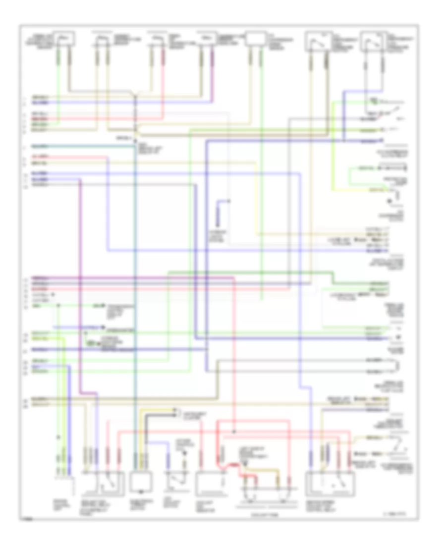
СИСТЕМА КОНДИЦИОНЕРА
Электросхема кондиционера (1 из 2) для Audi A6 1997
 https://portal-diagnostov.com/license.html
Automotive Electricians Portal FZCO
Automotive Electricians Portal FZCO
https://portal-diagnostov.com/license.html
https://portal-diagnostov.com/license.html
Automotive Electricians Portal FZCO
Automotive Electricians Portal FZCO
Электросхема кондиционера (1 из 2) для Audi A6 1997 - Список элементов:
- A/c control unit
- Air flow flap
- Auxiliary relay panel 2
- Battery(30)
- C 1995 vftc
- Central flap
- Connector
- Coolant 2-way valve
- Data
- Defroster
- Footwell/
- Fuse 15 5a
- Fuse 15a
- Fuse 30a
- Fuse 5a
- Fuse 60a
- Fuse/ relay panel
- G202 (behind left side of i/p)
- G203 (lower right "a" pillar)
- Hot at all times
- Hot w/ lights on
- Hot w/ load reduction relay energized (x)
- Ignition(15)
- Interior monitoring sensor control module
- Interior temperature fan & sensor
- Link
- Temp regulator flap motor
- Transmission control module (a/t)
Электросхема кондиционера (2 из 2) для Audi A6 1997
Электросхема кондиционера (2 из 2) для Audi A6 1997 - Список элементов:
- (behind left side of i/p)
- (in fuse/relay panel)
- (intake manifold) g131
- (left side of engine compartment)
- (lower left "a" pillar)
- (lower right "a" pillar)
- A/c compressor
- A/c compressor clutch
- A/c compressor clutch relay
- A/c refrigerant high pressure switch
- A/c refrigerant low pressure switch
- Ambient temperature sensor
- Blower motor
- C 1995 vftc
- C10
- C11
- Coolant fan control relay
- Coolant fan control thermo switch
- Coolant fan resistor
- Coolant fans
- Digital outside air temperature display
- Electronic thermo switch
- Engine control unit
- Fresh air blower control module
- Fresh air intake duct temperature sensor
- Fresh air recirculating flap valve
- Fresh air temperature sensor
- G100
- G200
- G202
- G202 (behind left side of i/p)
- G203
- Instrument cluster
- Interior lights system
- Interior monitoring sensor control module
- Low coolant switch
- Protection diode
- Red
- Second speed coolant fan control relay
- Speed sensor
- Speedometer
- Temperature sensor, headliner
- Transmission control module (a/t)

 Čeština
 Dansk
Dansk Deutsch
 Ελληνικά
 English
 English
 Español
 Suomi
Suomi Français
 Français
 עברית
עברית Hrvatski
 Magyar
 日本語
日本語 한국어
한국어 Nederlands
 Polski
 Português
 Português
 Română
 Русский
 Slovenčina
 Slovenščina
 Svenska
 Türkçe
 中文 (中国)