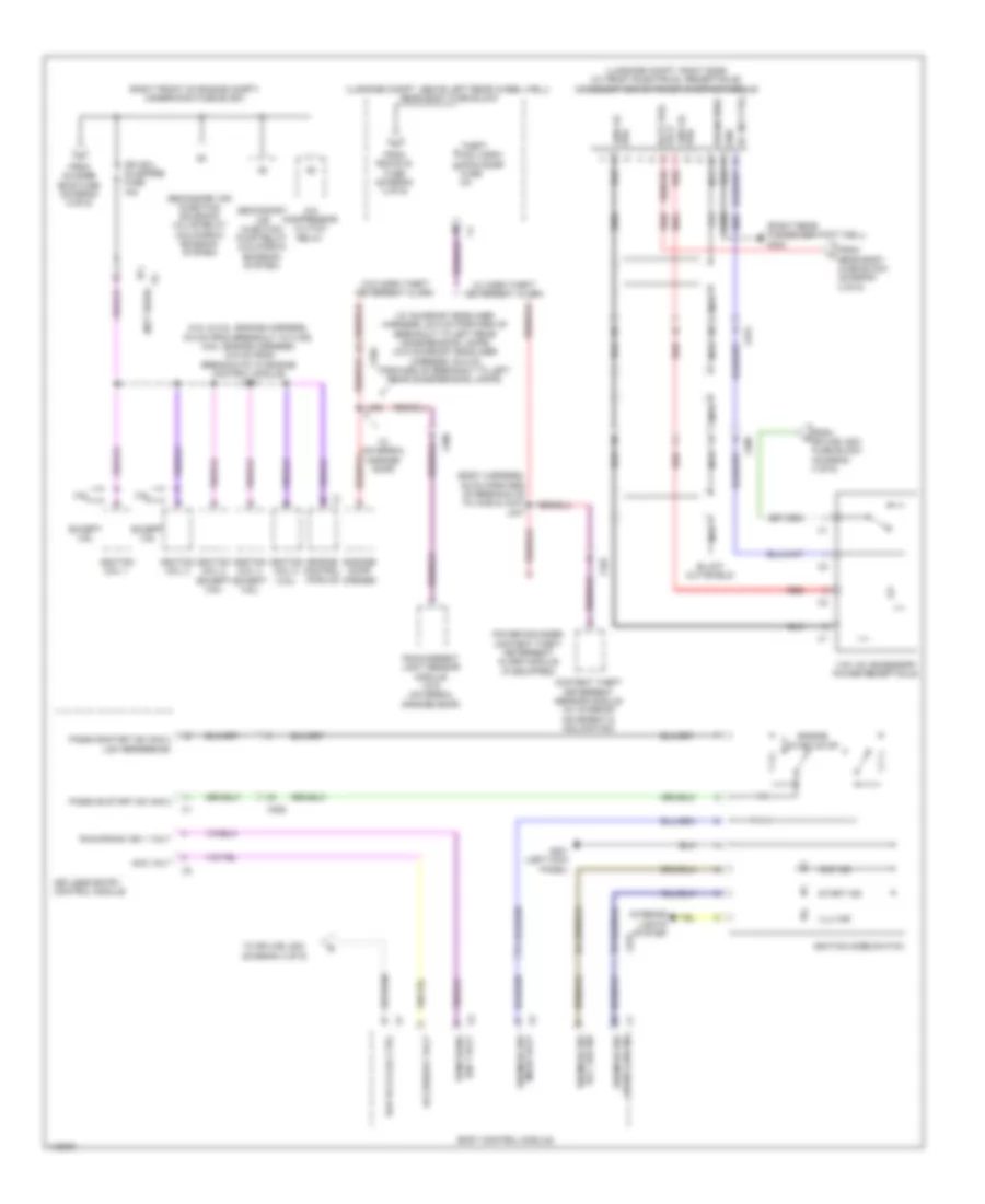
POWER DISTRIBUTION
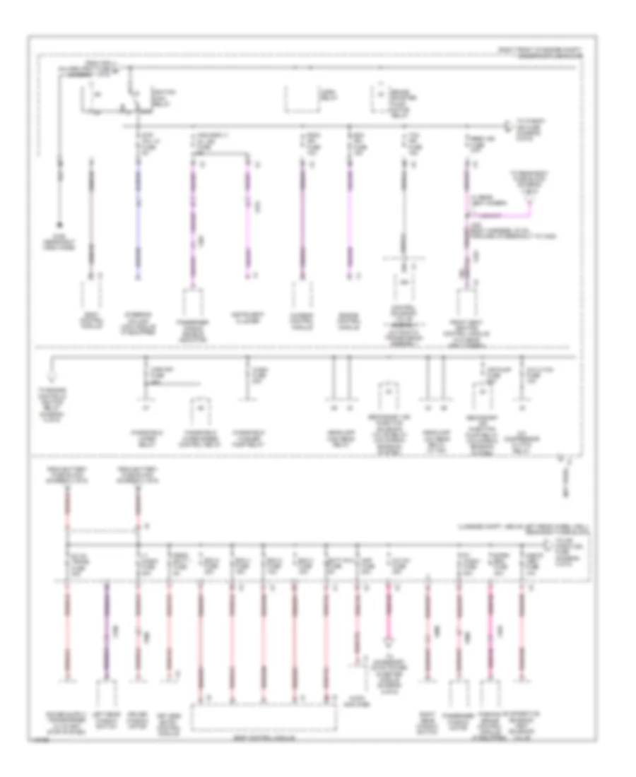
Power Distribution Wiring Diagram (1 of 6) for Cadillac ATS Luxury 2014
 https://portal-diagnostov.com/license.html
Automotive Electricians Portal FZCO
Automotive Electricians Portal FZCO
https://portal-diagnostov.com/license.html
https://portal-diagnostov.com/license.html
Automotive Electricians Portal FZCO
Automotive Electricians Portal FZCO
List of elements for Power Distribution Wiring Diagram (1 of 6) for Cadillac ATS Luxury 2014:
- (not used)
- (on battery) battery fuse block
- (right front of engine compt) auxiliary underhood fuse block
- (right front of engine compt) underhood fuse block
- 5cm from hood ajar switch breakout)
- Abs pump fuse 60a
- Abs vlv fuse 30a
- Afs ahl/ ped prot fuse 10a
- Ahl fuse 10a
- Automatic transmission assembly
- Battery
- Battery fuse holder
- Battery sensor module
- Bcm 1/ spare fuse 10a
- Bcm 5 fuse 15a
- Bcm 6 fuse 10a
- Bcm 7 fuse 10a
- Body control module
- Control solenoid valve assembly
- Cool fan fuse 60a
- Cooling fan control module (if equipped)
- Cooling fan motor (if equipped)
- Driver seat adjuster switch
- Driver seat memory control module
- Drvr pwr seat fuse 30a
- Electronic brake control module
- Front seat heating control module (if equipped)
- Fuse 100a
- Fuse 200a
- Fuse 250a
- Fuse 300a
- Fuse 60a
- Fuse 70a
- Fuse holder 5a
- Fuse n/a
- Generator
- Headlamp control module (w/ hid)
- Ign
- Keyless entry control module
- Left headlamp assembly (w/ hid)
- Nca
- Pass pwr seat fuse 30a
- Pass wndw sw fuse 10a
- Passenger seat adjuster switch
- Passenger window switch (w/ memory)
- Pedestrian impact detection control module (if equipped)
- Peps fuse 30a
- Power steering control module
- Red
- Right headlamp assembly (w/ hid)
- S/roof fuse 30a
- Spare/ htd seat2 fuse 15a
- Starter motor
- Starter relay
- Strtr fuse 30a
- Sunroof motor (if equipped)
- Tcm/spare fuse 15a
- To ignition main relay (diagram 2 of 6)
- To instrument panel fuse block (diagram 4 of 6)
- To rear body fuse block (diagram 2 of 6)
- W/ memory
- W/o memory
- X109
- X275
- X321
- X322
- X338
- X600
- X606
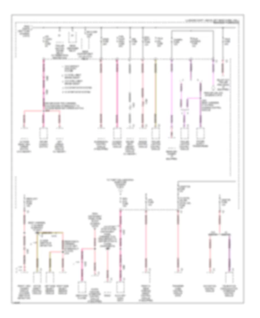
Power Distribution Wiring Diagram (2 of 6) for Cadillac ATS Luxury 2014
List of elements for Power Distribution Wiring Diagram (2 of 6) for Cadillac ATS Luxury 2014:
- (luggage compt, above left rear wheel well) rear body fuse block
- (not used)
- (right front of engine compt) underhood fuse block
- 87a
- A/c cltch fuse 10a
- A/c compressor clutch relay
- A/c inv fuse 30a
- Air pump fuse 50a
- Amp fuse 30a
- Aos disply/ mil ign fuse 5a
- Audio amplifier
- Automatic transmission assembly
- Batt rvc fuse 5a
- Bcm 2 fuse 10a
- Bcm 3 fuse 15a
- Bcm 4 fuse 15a
- Bcm 8 fuse 30a
- Body control module
- Brake booster pump motor relay
- Chassis control module
- Cnstr vent fuse 10a
- Control solenoid valve assembly
- Dc dc trans fuse 30a
- Driver window motor
- E/prk brk fuse 30a
- Ecm ign fuse 15a
- Engine control module
- Evaporative emission vent solenoid valve
- From afs ahl/ped prot fuse e (diagram 1 of 6)
- From battery fuse block (diagram 1 of 6)
- Front seat heating control module (w/o rear view camera)
- Fscm ign fuse 10a
- G106 (near right hood hinge)
- Headlamp high beam relay
- Headlamp low beam relay (w/ hid)
- Horn relay
- Ign
- Ignition main relay
- Instrument cluster
- J330 (body harness, 20 cm forward of breakout to x322)
- Keyless entry control module
- Left rear window switch
- Lt wndw fuse 30a
- Parking brake control module (if equipped)
- Passenger air bag disable indicator
- Passenger window motor
- Peps/ batt 1 fuse 5a
- Rbec ign fuse 20a
- Right rear window switch
- Rt wndw fuse 30a
- Secondary air injection pump relay (california emission system)
- Secondary air injection solenoid valve relay (california emission system)
- Steering column lock module (if equipped)
- Str col lk fuse 5a
- Tcm ign fuse 15a
- To accessory dc/ac power inverter module (diagram 6 of 6)
- To engine controls ignition relay (diagram 5 of 6)
- To ip body ign fuse (diagram 5 of 6)
- To mir wndw mdl fuse (diagram 3 of 6)
- To rear body fuse block (diagram 3 of 6)
- W/ rear view camera
- Wash fuse 20a
- Windshield washer pump relay
- Windshield wiper relay
- Windshield wiper speed control relay
- Wpr frt fuse 30a
- X275
- X301
- X322
- X403
- X500
- X600
- X700
- X800
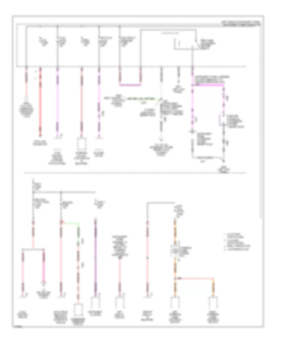
Power Distribution Wiring Diagram (3 of 6) for Cadillac ATS Luxury 2014
List of elements for Power Distribution Wiring Diagram (3 of 6) for Cadillac ATS Luxury 2014:
- (body harness, 17 cm rear of branch to g401) j402
- (driver door trim harness, 6 cm forward of breakout to outside rearview mirror switch) j505
- (instrument panel harness, 9 cm from branch to center stack & tunnel components) j209
- (luggage compt, above left rear wheel well) rear body fuse block
- (rear fascia harness, 12.5 cm left of breakout to x416) j416
- Active safety control module
- Auxiliary audio input
- Brake assist
- Camera fuse 10a
- Chassis control module
- Disc & mp3 player
- Driver seat memory control module (w/ memory)
- Driver window switch
- Ecm/ batt fuse 10a
- Engine control module
- From cnstr j vent fuse (diagram 2 of 6)
- From instrument panel fuse block (diagram 4 of 6)
- From splice j330 (diagram 2 of 6)
- Front & rear parking assist control module (if equipped)
- Front view camera module (w/o side obstacle detection)
- Fuel pump fscm fuse 20a
- Human machine interface control module (if equipped)
- J403 (body harness, 31 cm from chassis control module)
- Left mirror control module (w/ memory)
- Left side object sensor module
- Logistics fuse 10a
- Media disc player
- Mir wndw mdl fuse 5a
- Msm fuse 10a
- Navigation control module
- Onstar fuse 10a
- Outside rear view mirror switch (w/o memory)
- Pnk
- Radio
- Rdo/ dvd fuse 15a
- Rear compartment lid unlatch relay
- Rear defogger relay
- Rearview camera (if equipped)
- Right side object sensor module
- Rr closr fuse 10a
- Sads fuse 25a
- Sbza/ldw/ eocm fuse 15a
- Suspension control module (if equipped)
- Tc cntrl mdl/rr cntrl mdl fuse 15a
- Telematics communication interface control module
- To theft mdl/ugdo/rain snsr fuse (diagram 6 of 6)
- Trailer ignition power relay (w/ pedestrian protection)
- Trailer lighting control module
- Transfer case control module (awd)
- Trlr fuse 30a
- Trlr mdl fuse 40a
- Trlr/ sunshd fuse 10a
- Upa fuse 10a
- W/ intelligent
- W/ onstar
- W/ side obstacle detection
- W/ start/stop system
- W/o compact
- W/o intelligent
- W/o onstar
- W/o start/ stop system
- W/o start/stop system
- X150
- X206
- X225
- X321
- X337
- X415
- X500
- X505
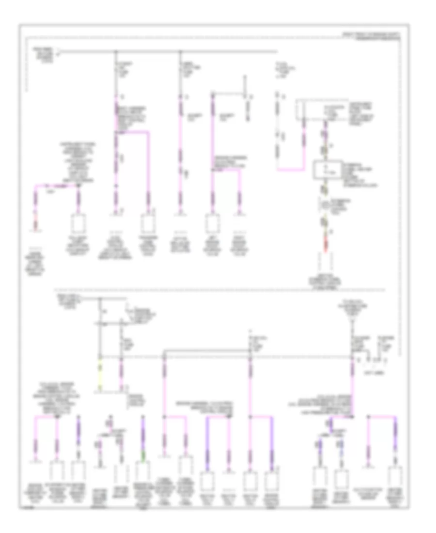
Power Distribution Wiring Diagram (4 of 6) for Cadillac ATS Luxury 2014
List of elements for Power Distribution Wiring Diagram (4 of 6) for Cadillac ATS Luxury 2014:
- (instrument panel harness, 12 cm from branch to steering column components) j202
- (instrument panel harness, 5 cm from breakout to hazard warning switch) j232
- (left side of instrument panel) instrument panel fuse block
- 22a
- 23a
- 24a
- 27a
- 27b
- 33b
- Apo circuit breaker fuse 15a
- Batt fuse 30a
- Blower motor
- Center console accessory power receptacle
- Data link connector
- Disply fuse 15a
- Dlc fuse 10a
- Early production
- Escl fuse 15a
- From auxiliary underhood fuse block (diagram 1 of 6)
- From body control module d (diagram 6 of 6)
- Frt/hvac blwr fuse 40a
- G201 (left kick panel)
- G202 (left kick panel)
- Headup display (if equipped)
- Hvac cntrl fuse 15a
- Hvac control module
- Hvac control module (w/ start/ stop system)
- Inflatable restraint sensing & diagnostic module
- Info display module
- Instrument cluster
- Instrument panel accessory power receptacle
- J297
- Late production
- Left steering wheel controls switch
- Passenger presence module
- Rdo dvd/ hvac tntrl fuse 15a
- Red
- Retained accessory power relay
- Right steering wheel controls switch
- Sdm/aos fuse 10a
- Steering column lock module (if equipped)
- Steering wheel air bag coil
- Str/ whl/ cntrl fuse 2a
- To 110v ac accessory power receptacle (diagram 6 of 6)
- To splice j209 (diagram 3 of 6)
- W/ front electrical receptacle
- W/ start/ stop system
- W/o start/ stop system
- X206
- X211
- X224
- X275
- X322
Power Distribution Wiring Diagram (5 of 6) for Cadillac ATS Luxury 2014
List of elements for Power Distribution Wiring Diagram (5 of 6) for Cadillac ATS Luxury 2014:
- (2.0l & 2.5l: engine 9.5 cm from branch to x150) (3.6l: engine harness, 35 cm rear of breakout to high pressure fuel pump) j134
- (2.0l & 2.5l: engine harness, 7.5 cm from breakouts to engine control module) (3.6l: engine harness, 4 cm from breakout for ignition coil 5) j132
- (diagram 2 of 6)
- (engine harness, 13.5 cm from breakouts to engine control module) j136
- (engine harness, 6.5 cm from branch to x150) j140
- (instrument panel harness, 5 cm from branch to ambient light/sunload sensor) (w/ headup display & w/o light sentive mirror) j207
- (not used)
- (right front of engine compt) underhood fuse block
- 25a
- 25b
- 3.6l
- 7.5a
- Active grille air shutter actuator
- Aero shutter fuse 10a
- Body harness, 5.5 cm above breakouts to body control module (awd) j221
- Collision alert indicators (w/o headup display)
- Controls ignition relay
- Ecm fuse 25a
- Engine
- Engine control module
- Engine control module (3.6l)
- Engine coolant thermostat heater (2.5l)
- Engine oil pressure control solenoid valve (except 3.6l)
- Evaporative emission purge solenoid valve
- Except 2.5l
- Except 3.6l
- From rbec ign fuse k
- From wpr frt fuse l (diagram 2 of 6)
- Heated oxygen sensor 1
- Heated oxygen sensor 1 bank 2 (3.6l)
- Heated oxygen sensor 2
- Heated oxygen sensor 2 bank 2 (3.6l)
- Heated oxygen sensor bank 1 sensor 1
- Heated oxygen sensor bank 1 sensor 2
- Heating steering wheel control module (if equipped)
- Htd str whl fuse 15a
- Htd/str/ whl fuse 7.5a
- Hvac control module (w/o headup display & light sensitive mirror)
- Ign coil inj fuse 15a
- Ignition coil 2 (3.6l)
- Ignition coil 4 (3.6l)
- Ignition coil 6 (3.6l)
- Inside rearview mirror (w/ light sensitive mirror)
- Instrument panel fuse block (left side of instrument panel)
- Ip body ign fuse 10a
- Left engine mount solenoid valve
- Multi-function intake air sensor
- O2 snsr emis fuse 10a
- Red
- Right engine mount solenoid valve
- Spare pt fuse 10a
- Steering wheel air bag coil
- Steering wheel heater fuse holder (bottom of steering column)
- To ign coil inj/spare fuse (diagram 6 of 6)
- Transfer case control module (awd)
- Turbo- charger bypass solenoid valve (2.0l turbo)
- Turbo- charger wastegate solenoid valve (2.0l turbo)
- X100
- X275
- X301
Power Distribution Wiring Diagram (6 of 6) for Cadillac ATS Luxury 2014
List of elements for Power Distribution Wiring Diagram (6 of 6) for Cadillac ATS Luxury 2014:
- (2.0l & 2.5l: engine harness, 9.5 cm from breakout to x160) (3.6l: engine harness, 12.5 cm from breakouts to engine control module) j131
- (body harness, 45 cm forward of breakouts to x335 & x337) j347
- (luggage compt, above left rear wheel well) rear body fuse block
- (luggage compt, right side) (w/ front electrical receptacle) accessory dc/ac power inverter module
- (not used)
- (right front of engine compt) underhood fuse block
- (right rear passenger foot well) g304
- (w/ sunroof headliner harness, 20.5 cm forward of breakout to left rear dome/reading lamps) (w/o sunroof headliner harness, 53.5 cm forward of breakout to left rear dome/reading lamps)
- 110v ac accessory power receptacle
- 120v ac phb
- 3.6l
- A/c compressor clutch relay
- Ac inv ctrl
- Acc ind
- Acc led sig ign mode sw
- Acc volt
- Accessory volt
- Body control module
- Content theft deterrent sensor module (w/ interior movement & inclination)
- Drain wire
- Engine control module
- Engine start/stop
- Except 3.6l
- From o2 snsr emis fuse (diagram 5 of 6)
- From rdo/dvd fuse (diagram 3 of 6)
- From rear body fuse block (diagram 2 of 6)
- From splice j203 fuse block (diagram 4 of 6)
- G201 (left kick panel)
- Garage door opener
- Gnd
- Ign 1 volt run/crank
- Ign coil inj/spare fuse 15a
- Ignition coil 1
- Ignition coil 2 (except 3.6l)
- Ignition coil 3
- Ignition coil 4 (except 3.6l)
- Ignition coil 5 (3.6l)
- Ignition mode switch
- Illu ind
- Interior lights system
- J306
- Keyless entry control module
- Mode volt ign mode sw
- Nca
- Passive start sw sig 2
- Passive start sw sig 2 low reference
- Pha 120v ac
- Power sounder content theft deterrent alarm module (if equipped)
- Rain/ambient light sensor module (w/o universal garage door)
- Rap rly2 coil ctrl
- Red
- Run/crank ign 1 volt
- Secondary air injection pump relay (california emission system)
- Secondary air injection solenoid valve relay (california emission system)
- Start ind
- Start led sig ign mode sw
- Theft mdl/ugdo/ rain snsr fuse 5a
- To splice j203 (diagram 4 of 6)
- Volt batt pos
- W/ horn theft deterrent alarm
- W/ universal garage door
- W/o horn theft deterrent alarm
- X206
- X225
- X275
- X306
- X335
- X337

 Čeština
 Dansk
Dansk Deutsch
 Ελληνικά
 English
 English
 Español
 Suomi
Suomi Français
 Français
 עברית
עברית Hrvatski
 Magyar
 日本語
日本語 한국어
한국어 Nederlands
 Polski
 Português
 Português
 Română
 Русский
 Slovenčina
 Slovenščina
 Svenska
 Türkçe
 中文 (中国)