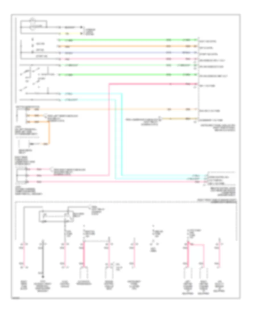
POWER DISTRIBUTION
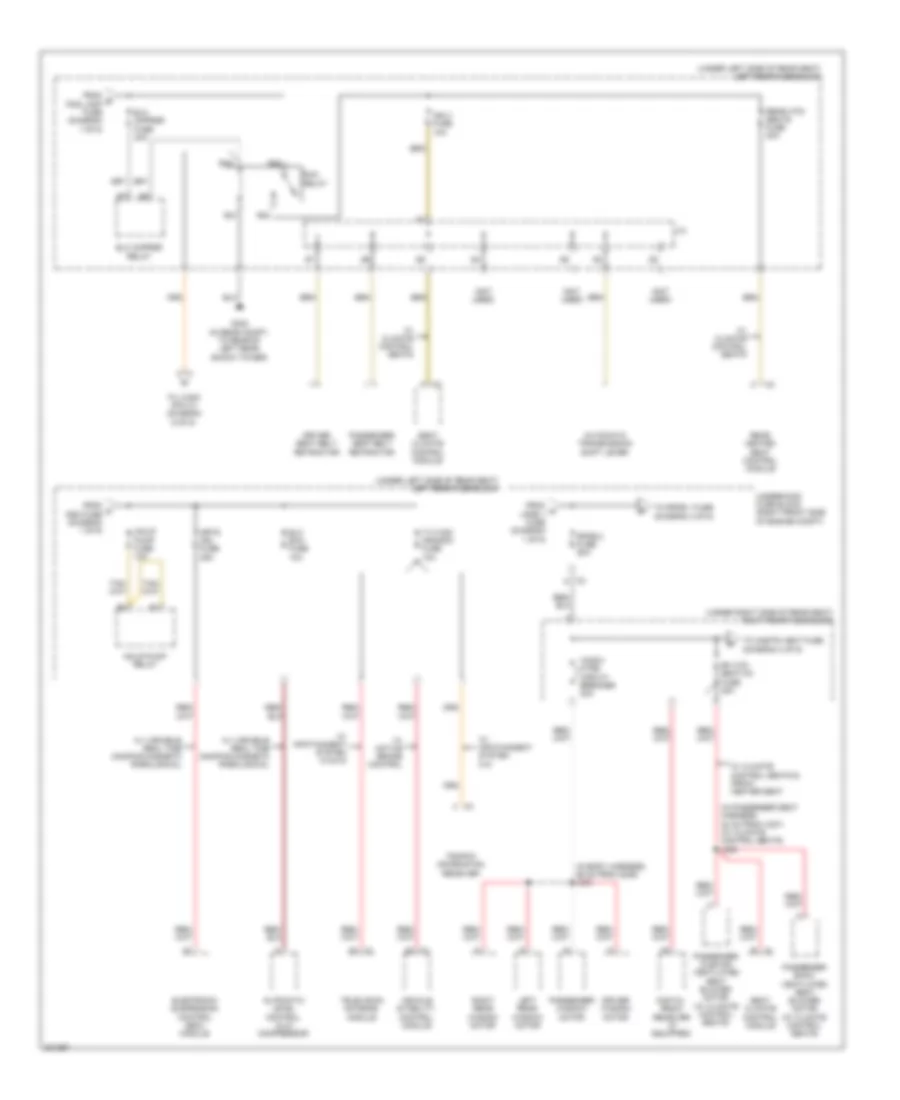
Power Distribution Wiring Diagram (1 of 6) for Cadillac STS V 2009
 https://portal-diagnostov.com/license.html
Automotive Electricians Portal FZCO
Automotive Electricians Portal FZCO
https://portal-diagnostov.com/license.html
https://portal-diagnostov.com/license.html
Automotive Electricians Portal FZCO
Automotive Electricians Portal FZCO
List of elements for Power Distribution Wiring Diagram (1 of 6) for Cadillac STS V 2009:
- (in passenger seat harness, 24 cm from passenger seat adjuster switch connector) j353
- (right front side of engine compt) underhood fuse block
- (under left side of rear seat) left rear fuse block
- 200a
- Abs fuse 25a
- Abs mtr fuse 50a
- Air bag/ batt fuse 10a
- Amp fuse 30a
- Audio amplifier
- Battery
- Bck/up lamp fuse 10a
- Bck/up lamp relay
- Ddm fuse 15a
- Driver back ventilated seat blower motor
- Driver cushion ventilated seat blower motor
- Driver door module (ddm)
- Driver seat adjuster switch
- Driver seat lumbar switch
- Electronic brake control module (ebcm)
- Generator
- Inflatable restraint sensing & diagnostic module (sdm)
- Inline fuse generator
- J/c
- J302 (in body harness, 58 cm from right rear fuse block c1)
- Left front speaker
- Left rear door control module
- Left rear fuse block (under left side of rear seat)
- Lpdb 1 fuse 50a
- Lpdb 2 fuse 50a
- Lt pos relay
- Memory seat module (msm)
- Memory seat module (msm) (if equipped)
- Msm fuse 10a
- Passenger seat adjuster switch
- Passenger seat lumbar switch
- Pos lamp fuse 10a
- Pwr seats circuit breaker 30a
- R13
- R18
- R26
- R29
- R31
- R32
- R36
- R37
- Rear dr mdl fuse 15a
- Rear shlf spkr fuse 15a
- Red
- Red/ (in passenger seat harness, 17 cm from passenger seat adjuster switch connector) j354
- Right rear door control module
- Rt pos relay
- S12
- S13
- S14
- S20
- S21
- S22
- S23
- Speaker
- Starter motor
- Stdby lamp relay
- Subwoofer
- To elc cmprsr fuse (diagram 2 of 6)
- To inclr pump fuse (diagram 2 of 6)
- To rpdb 2 fuse (diagram 2 of 6)
- Trunk relse relay
- Trunk relse sw fuse 7.5a
- Valet switch
- W/ climate control seats
- W/ infotainment system 010
- W/ infotainment system 012/014/015
- W/ power lumbar seat
- W/o power lumbar seat
- X1 b
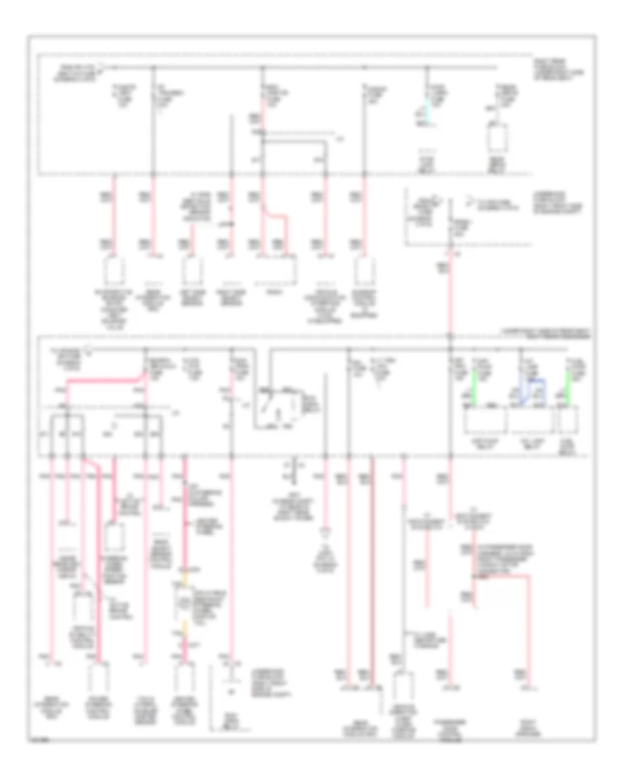
Power Distribution Wiring Diagram (2 of 6) for Cadillac STS V 2009
List of elements for Power Distribution Wiring Diagram (2 of 6) for Cadillac STS V 2009:
- (in body harness, 86 cm from g306) j303
- (in passenger seat harness, 32 cm from x307) (w/ climate control seats) j355
- (not used)
- (under left side of rear seat) left rear fuse block
- (under right side of rear seat) right rear fuse block
- Automatic level control (alc) compressor
- Automatic transmission shift lever
- B x1
- C x2
- Digital radio receiver (if equipped)
- Driver seat belt retractor
- Driver window motor
- Elc cmprsr fuse 30a
- Elc cmprsr relay
- Elc exh fuse 10a
- Electronic suspension control (esc) module
- From a lpdb 1 fuse (diagram 1 of 6)
- From b pos lamp fuse (diagram 1 of 6)
- From c ddm fuse (diagram 1 of 6)
- G402 (in rear compt, to rear of left rear shock tower)
- Ign 3 fuse 10a
- Inclr pump fuse 10a
- Inclr pump relay
- J/c
- Left rear window motor
- Mrtd mdl fuse 25a
- Passenger back ventilated seat blower motor (w/ climate control seats)
- Passenger cushion ventilated seat blower motor (w/ climate control seats)
- Passenger seat belt retractor
- Passenger window motor
- R21
- R22
- R23
- R25
- Rear heated seat control module
- Rear htd/ seats fuse 20a
- Rf htd/ seat/xm fuse 20a
- Right rear window motor
- Rpdb 2 fuse 50a
- Run relay
- Seat climate control module
- Television antenna module
- To cnstr vent fuse (diagram 3 of 6)
- To jx300 (pin 31) (diagram 6 of 6)
- To rpdb 1 fuse (diagram 3 of 6)
- Traffic information receiver
- Tv/vics/ afs/scm fuse 10a
- Underhood fuse block (right front side of engine compt)
- Vehicle stability control module
- W/ active brake control
- W/ climate control seats
- W/ climate control seats & front heater seat
- W/ infotainment system
- W/ infotainment system 014/015
- W/ variable real time damping magneto rheological
- Wndw mtrs circuit breaker 30a
Power Distribution Wiring Diagram (3 of 6) for Cadillac STS V 2009
List of elements for Power Distribution Wiring Diagram (3 of 6) for Cadillac STS V 2009:
- (under right side of rear seat) right rear fuse block
- A x3
- Cnstr vent fuse 10a
- D x276
- Diff pump fuse 15a
- Diff pump relay
- Evaporative emission (evap) canister vent solenoid valve
- From d rpdb 2 fuse (diagram 2 of 6)
- From rf htd/ e seat/xm fuse (diagram 2 of 6)
- Frt pdm fuse 15a
- Fuel pump fuse 20a
- Fuel pump relay
- G401 (in rear compt, to rear of right rear shock tower)
- Harness)
- Heated steering wheel control module
- Heater steering wheel
- Htd str fuse 7.5a
- Inflatable restraint steering wheel module coil
- Inside rearview mirror (isrvm)
- Int lamp fuse 10a
- Int lamp relay
- J/c
- J221 (in steering column pnk
- J407
- Left side object sensor
- Lt trn/ ldw fuse 10a
- Passenger door control module
- Pnk
- Power steering control module
- R12
- R16
- R17
- R21
- R22
- R23
- R25
- R26
- R27
- R37
- Radio
- Rdo/ onstar fuse 10a
- Rear defog relay
- Rear integration module (rim)
- Rear object sensor control module
- Rear/ defog fuse 40a
- Red/ (in passenger door harness, 34 cm from front passenger window motor connector) j602
- Right front speaker
- Right rear fuse block (under right side of rear seat)
- Right side object sensor
- Rim fuse 10a
- Rim/rpa/ isrvm/clm fuse 10a
- Rpdb 1 fuse 50a
- Rt trn/sbza fuse 10a
- Run/ crnk fuse 10a
- Run/ crnk relay
- S/roof fuse 20a
- S10
- S11
- S15
- S16
- S17
- S22
- S23
- S24
- S25
- Steering wheel speed/ position sensor
- Stop lamp relay
- Stop lamps fuse 10a
- Sunroof control module (if equipped)
- Tan
- To afs fuse (diagram 4 of 6)
- To air bag/ ign fuse (diagram 4 of 6)
- To jx201 (pin 10) (diagram 6 of 6)
- Underhood fuse block (right front side of engine compt)
- Vehicle communication interface module (vcim) (if equipped)
- Vehicle direction alert alarm warning module
- Vehicle stability control module
- W/ active brake control
- W/ infotainment system 010
- W/ infotainment system 012/ 014/015
- W/ lane departure warning
- W/ side obstacle detection sensor indicator
- X277 d
- Yaw & lateral acceler ometer sensor
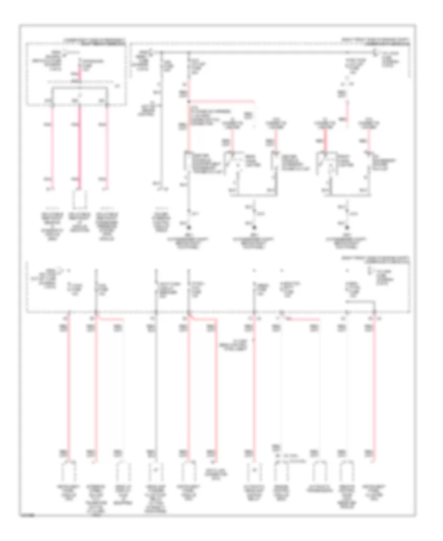
Power Distribution Wiring Diagram (4 of 6) for Cadillac STS V 2009
List of elements for Power Distribution Wiring Diagram (4 of 6) for Cadillac STS V 2009:
- (3.6l)
- (4.4l/4.6l)
- (right front side of engine compt) underhood fuse block
- (under right side of rear seat) right rear fuse block
- Afs fuse 30a
- Air bag/ign fuse 10a
- Automatic headlamp dimming relay
- Automatic transmission
- Aux outlet fuse 20a
- Center console accessory power outlet
- Center console compartment accessory power outlet
- Data link connector (dlc)
- Ecm/tcm batt fuse 10a
- Ekm/ ip mdl fuse 10a
- Engine control module (ecm)
- From f rpdb 1 fuse (diagram 3 of 6)
- From g rim/rpa/ isrvm/clm fuse (diagram 3 of 6)
- From h frt pwr outlet fuse (diagram 4 of 6)
- Front cigar lighter
- Frt pwr outlet fuse 15a
- G201 (in passenger compt, behind right kick panel)
- Hdlp wash circuit breaker 30a
- Head up display (hud) (if equipped)
- Headlamp washer fluid pump relay (w/ high intensity discharge)
- Hud fuse 10a
- I/beam fuse 15a
- I/p accessory power outlet
- I/p mdl/ aldl fuse 10a
- Inflatable restraint i/p module indicator
- Inflatable restraint passenger presence system (pps) module
- Inflatable restraint sensing & diagnostic module (sdm)
- Instrument panel cluster (ipc)
- Instrument panel module (ipm)
- J/c
- J212
- J311
- Pnk
- Power steering control module (pscm)
- Rear cigar lighter
- Red
- Remote control door lock receiver (rcdlr)
- S18
- S19
- S20
- S21
- Steering wheel/ column tilt/ telescope switch (w/ alarm taxi)
- To v/chk fuse (diagram 4 of 6)
- To wpr fuse (diagram 5 of 6)
- V/chk fuse 10a
- W/ active brake control
- W/ cigarette lighter
- W/ high beam control intelligent
- W/o cigarette lighter
- X1 h
Power Distribution Wiring Diagram (5 of 6) for Cadillac STS V 2009
List of elements for Power Distribution Wiring Diagram (5 of 6) for Cadillac STS V 2009:
- (in body harness, 55.5 cm from x305 inline connector) (w/ wiper system) j411
- (right front side of engine compt) underhood fuse block
- A/c cltch fuse 10a
- A/c cmprsr cltch relay
- Accy relay
- Blwr fuse 40a
- Ccp/ rly coils fuse 10a
- Distance sensing cruise control (dscc) module
- Fan 1 fuse 30a
- Fan 2 fuse 30a
- Fog lamp relay
- From ekm/ i i/p mdl fuse (diagram 4 of 6)
- From j blwr fuse (diagram 5 of 6)
- Frt blwr relay
- Fuel cool fuse 10a
- Fuel cool relay
- G104 (on right front frame rail, near bumper bracket)
- Headlamp leveling module (if equipped)
- Headlamp washer fluid pump relay (if equipped)
- Hi beam relay
- Hi fan spd relay
- Hid
- Horn fuse 15a
- Horn relay
- Hvac control module
- Lo beam w/o hid/ hid relay
- Lo fan spd relay
- Prk lamp relay
- Pwr/trn relay
- Rain snsr/ tpm fuse 7.5a
- Strtr fuse 30a
- Strtr relay
- Tire pressure module (if equipped)
- To instrument panel module (ipm) (pin 1 connector x2) (diagram 6 of 6)
- To pwr/trn relay (diagram 5 of 6)
- To run crnk relay (diagram 6 of 6)
- Traffic information receiver
- W/ adaptive automatic cruise control
- W/ cover wheel
- W/ infotainment system 015
- W/ tire pressure
- W/ wiper system
- W/o cover wheel
- W/o tire pressure
- Windshield outside moisture sensor (if equipped)
- Windshield wiper inhibit relay
- Windshield wiper/ washer switch
- Wpr fuse 30a
- Wpr hi relay
- Wpr spd relay
- Wpr sw/vics fuse 7.5a
- X320
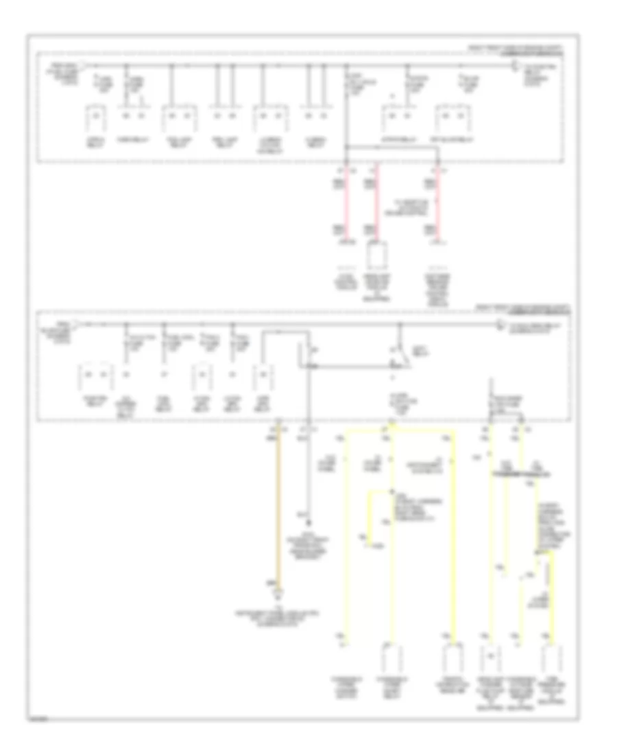
Power Distribution Wiring Diagram (6 of 6) for Cadillac STS V 2009
List of elements for Power Distribution Wiring Diagram (6 of 6) for Cadillac STS V 2009:
- (not used)
- (right front side of engine compt) underhood fuse block
- 3.6l
- 4.4l & 4.6l
- Abs ign fuse 15a
- Acc ind
- Accessory voltage
- Accy ind cntrl
- Air quality sensor (if equipped)
- Automatic transmission
- Ccp fuse 10a
- Ecm/tcm ign fuse 15a
- Engine control module (ecm)
- From accy relay (diagram 5 of 6)
- From left rear fuse block (run relay) (diagram 2 of 6)
- From right rear fuse block (run/crnk relay) (diagram 3 of 6)
- From underhood fuse block n (accy relay) (diagram 5 of 6)
- G104 (on right front frame rail, near bumper bracket)
- Htd wash/ aqs fuse 10a
- Hvac control module
- Ign 1 voltage
- Ign mode sw sply volt
- Ignition mode switch
- Illum
- Instrument panel cluster (ipc)
- Instrument panel module (ipm) (right side of dash, behind glove box)
- Interior lights system
- Ipm ign mode data sig
- Ipm ign mode sw ref volt
- Jx201 (on dash harness, under dashboard, near firewall grommet)
- Jx300 (on left frame rail, near left side of passenger seat)
- Left heated washer nozzle (if equipped)
- Mode control b/u
- Off
- Off in cntrl
- Off ind
- Pnk
- Rear defog relay
- Remote control door lock receiver (rcdlr) (under rear speaker shelf)
- Right heated washer nozzle (if equipped)
- Right rear fuse block
- Right rear fuse block (under right side of rear seat)
- Run crnk relay
- Run ign 3 voltage
- Start
- Start ind
- Start ind cntrl
- Voltage b/u

 Čeština
 Dansk
Dansk Deutsch
 Ελληνικά
 English
 English
 Español
 Suomi
Suomi Français
 Français
 עברית
עברית Hrvatski
 Magyar
 日本語
日本語 한국어
한국어 Nederlands
 Polski
 Português
 Português
 Română
 Русский
 Slovenčina
 Slovenščina
 Svenska
 Türkçe
 中文 (中国)