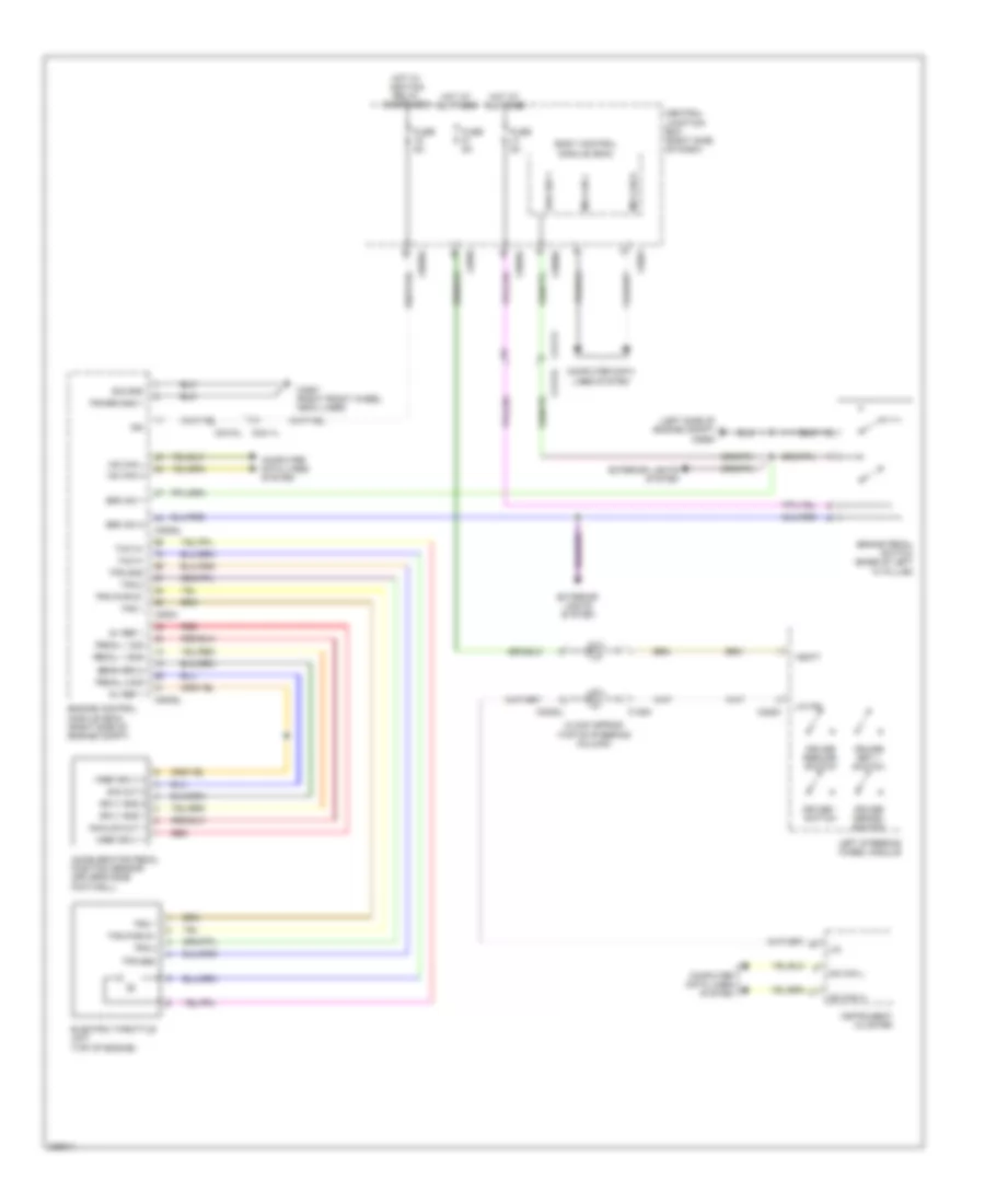
CRUISE CONTROL
Cruise Control Wiring Diagram for Land Rover Discovery 4 HSE 2010
List of elements for Cruise Control Wiring Diagram for Land Rover Discovery 4 HSE 2010:
- (left side of engine compt) c2564
- 5v ref 1
- Accelerator pedal position sensor (driver's side footwell)
- Analog out 1
- Body control module (bcm)
- Brake pedal switch (base of left "a" pillar)
- Brk sw 1
- Brk sw 2
- C0082l
- C0581
- C0582
- C0585l
- C0586l
- C0634
- C0635l
- C1254
- C2283
- C2411l
- C2412l
- C3557 (right front wheel arch liner)
- Central junction box (right side of dash)
- Clock spring (top of steering column)
- Computer data lines system
- Cruise - switch
- Cruise cencel switch
- Cruise resume switch
- Cruise set + switch
- Electric throttle unit (top of engine)
- Engine control module (ecm) (right side of engine compt)
- Exterior lights system
- Fuse 5a
- Hot at all times
- Hot w/ ignition relay energized
- Hs can h
- Hs can l
- Ign
- Instrument cluster
- Left steering wheel module
- Lin
- Lin ipc
- Ms can h
- Ms can l
- Pedal 1 gnd
- Pedal 1 sig
- Pedal 2 sig
- Power gnd 1
- Red
- Sig gnd
- Sig out 2
- Sply gnd 1
- Sply gnd 2
- Thc m+
- Thc m-
- Tps 1
- Tps 2
- Tps gnd
- Tps pwr 5v
- Vbatt
- Vref sply 1
- Vref sply 2
 Čeština
 Dansk
Dansk Deutsch
 Ελληνικά
 English
 English
 Español
 Suomi
Suomi Français
 Français
 עברית
עברית Hrvatski
 Magyar
 日本語
日本語 한국어
한국어 Nederlands
 Polski
 Português
 Português
 Română
 Русский
 Slovenčina
 Slovenščina
 Svenska
 Türkçe
 中文 (中国)
 Italiano