ENGINE PERFORMANCE
2.0L HYBRID
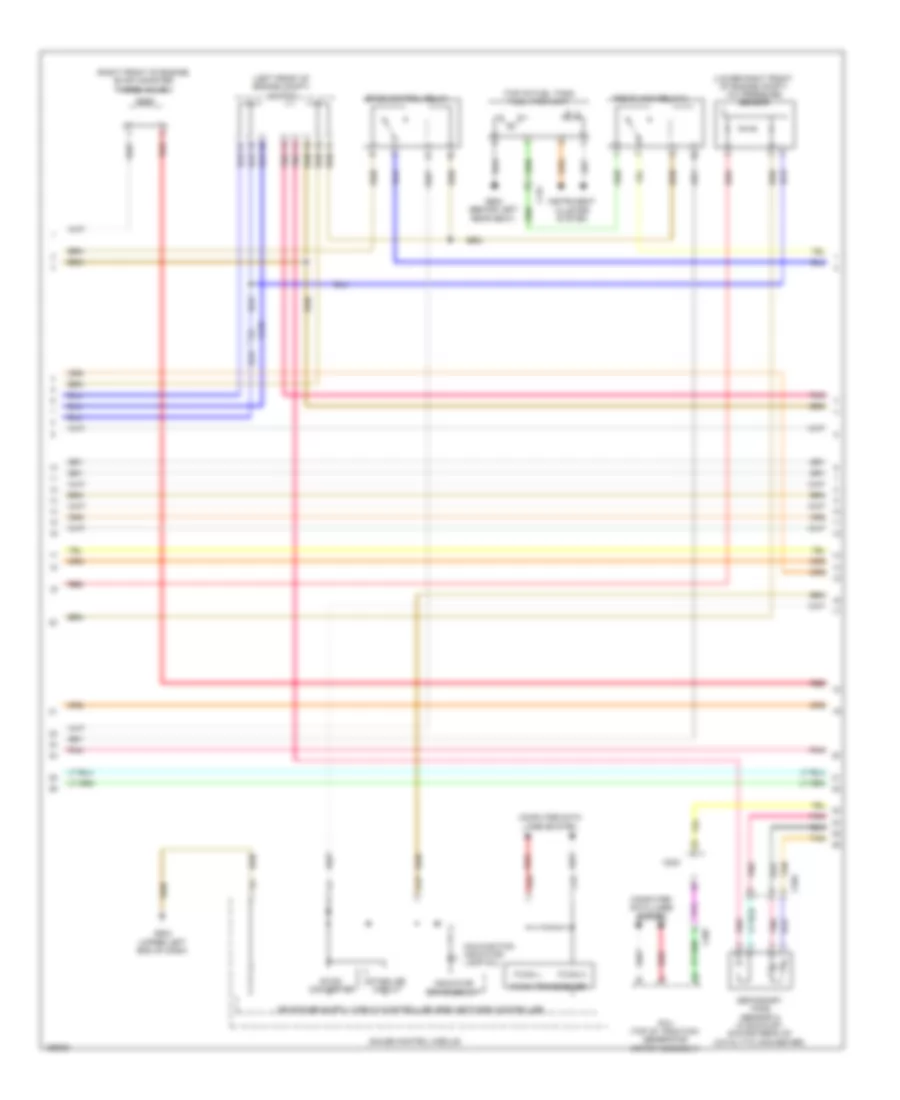
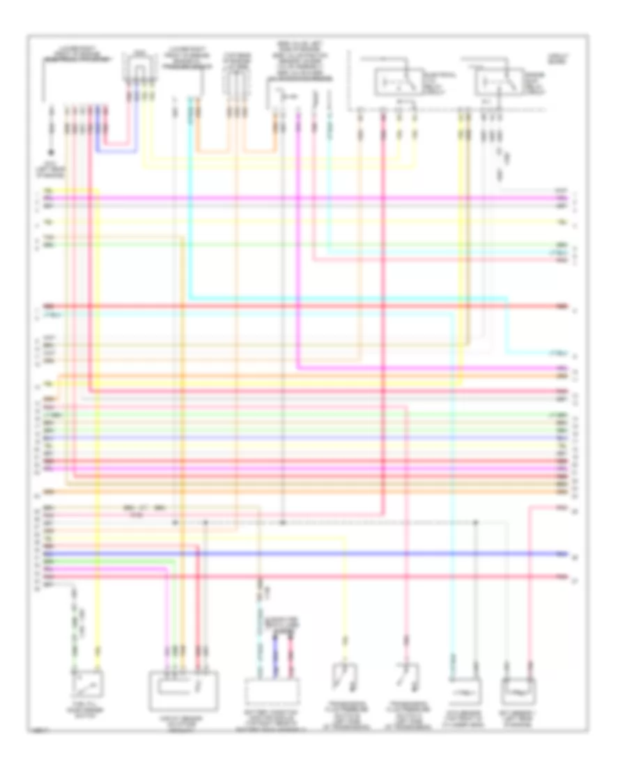
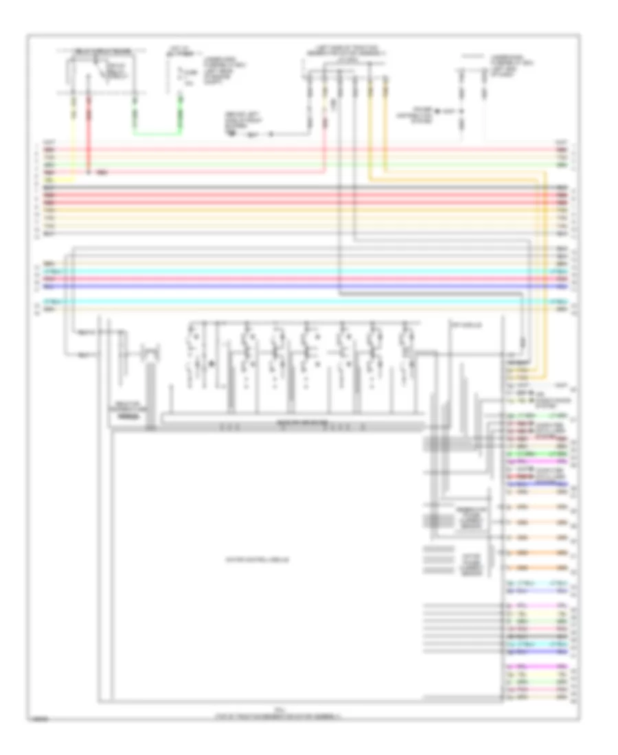
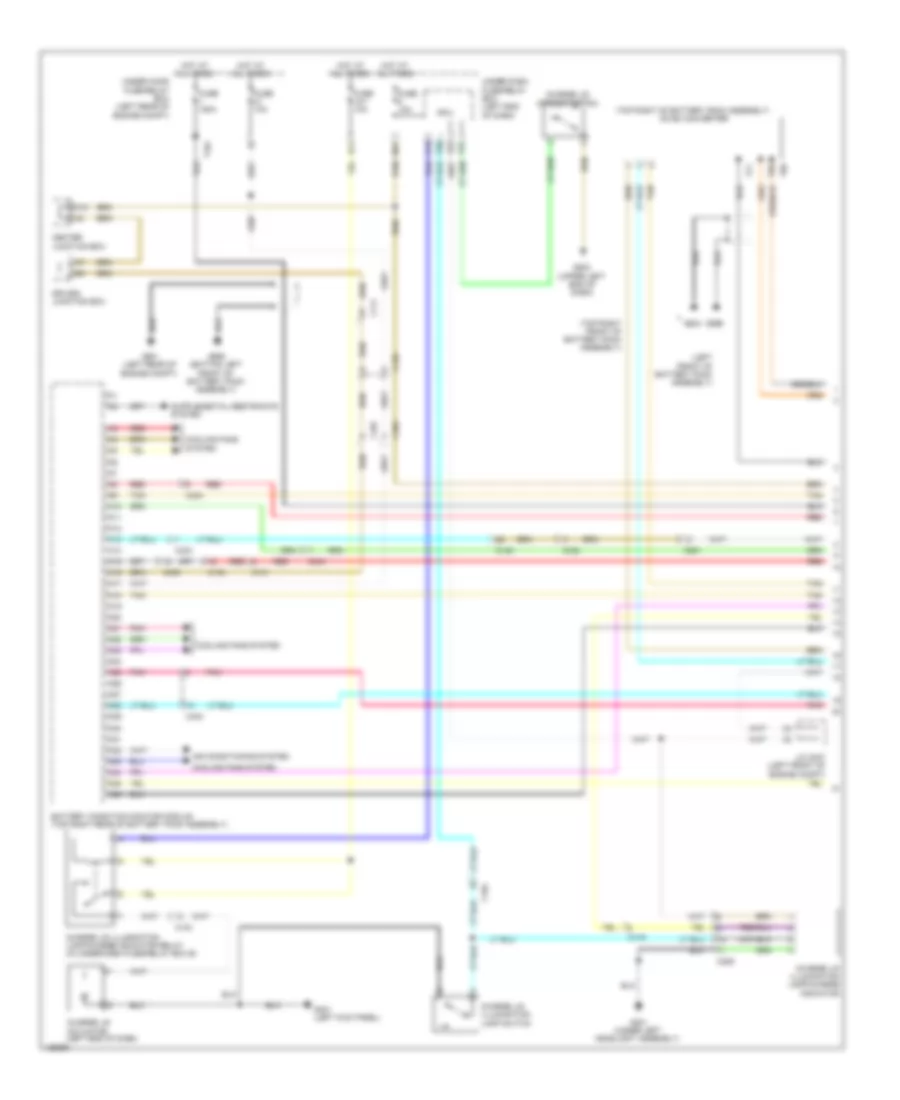
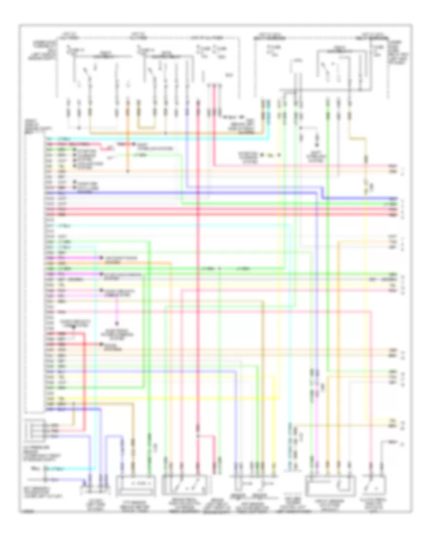
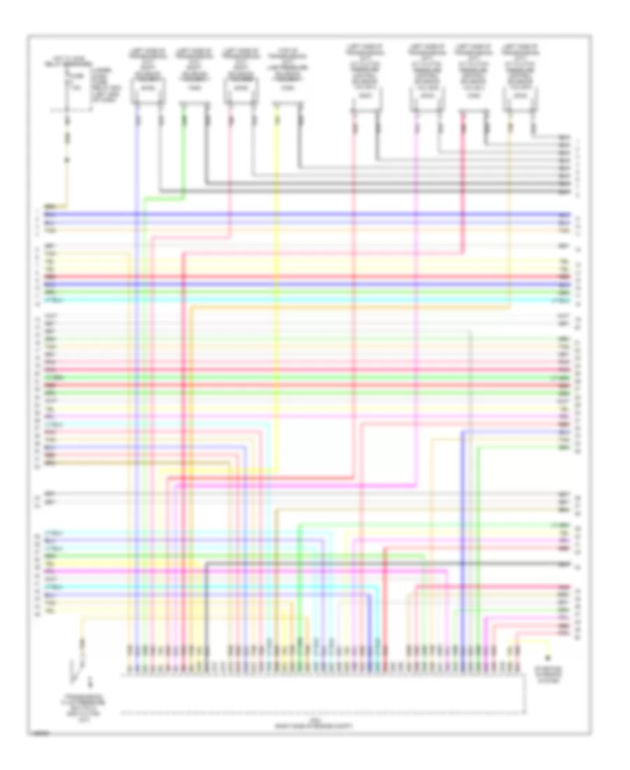
2.0L Hybrid, Engine Controls Wiring Diagram, Except Plug-In Hybrid (1 of 6) for Honda Accord Plug-In 2014
 https://portal-diagnostov.com/license.html
Automotive Electricians Portal FZCO
Automotive Electricians Portal FZCO
https://portal-diagnostov.com/license.html
https://portal-diagnostov.com/license.html
Automotive Electricians Portal FZCO
Automotive Electricians Portal FZCO
List of elements for 2.0L Hybrid, Engine Controls Wiring Diagram, Except Plug-In Hybrid (1 of 6) for Honda Accord Plug-In 2014:
- A10
- A11
- A12
- A13
- A14
- A15
- A16
- A17
- A18
- A19
- A20
- A21
- A22
- A23
- A24
- A25
- A26
- A27
- A28
- A29
- A30
- A31
- A32
- A33
- A34
- A35
- A36
- A37
- A38
- A39
- A40
- A41
- A42
- A43
- A44
- A45
- A46
- A47
- A48
- A49
- A50
- A51
- Anti-lock brakes system
- App sensor (on accelerator pedal support)
- App sensor a
- App sensor b
- C102
- C110
- C112
- C127
- C128
- C203
- Computer data lines system
- Cooling fans system
- Door locks system
- Ect sensor 2 (on radiator lower left outlet)
- Evap canister vent shut valve (under middle rear of vehicle, on evap control canister)
- Ftp sensor (behind center of fuel tank)
- Fuse 10a
- Fuse 15a
- Fuse 2-3 20a
- Fuse 20a
- Fuse 7.5a
- G101 (left rear of engine)
- Hot at all times
- Pcm (left front of engine compt)
- Pgm-fi main relay 1
- Pgm-fi sub relay
- Pnk
- Red
- Rfc relay
- Shift interlock system
- Shift solenoid valve a (left side of transmission)
- Shift solenoid valve b (left side of transmission)
- Under- hood fuse/ relay box (left rear of engine compt)
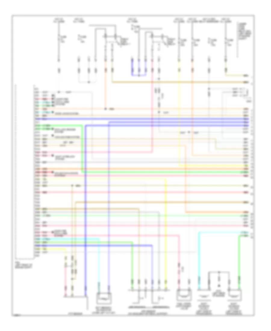
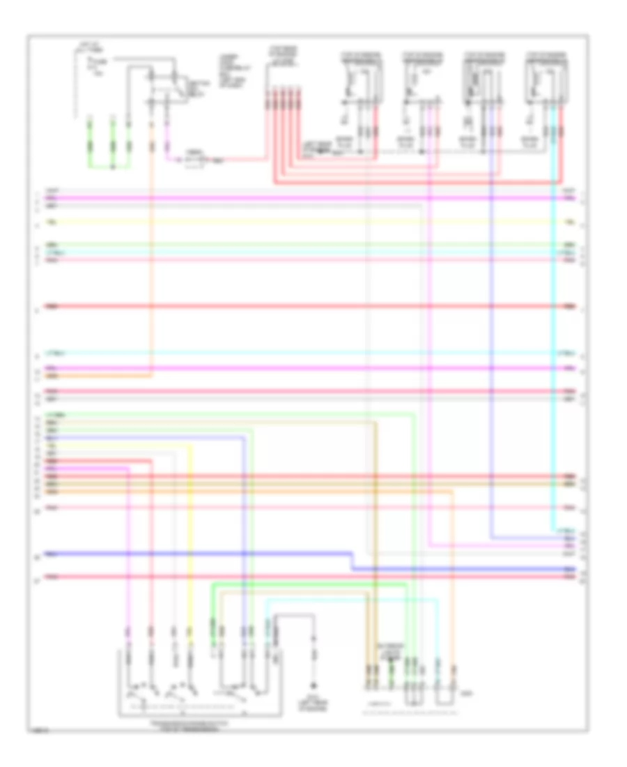
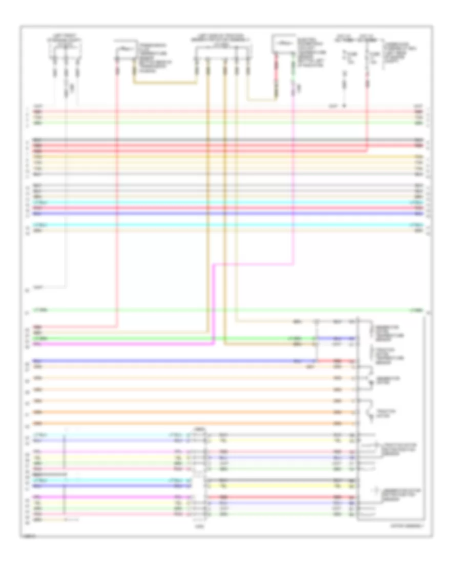
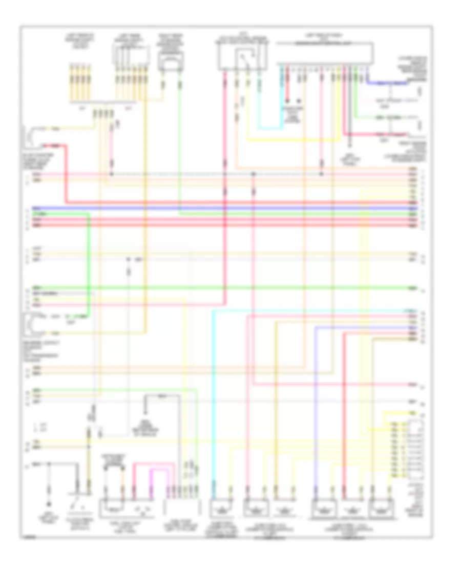
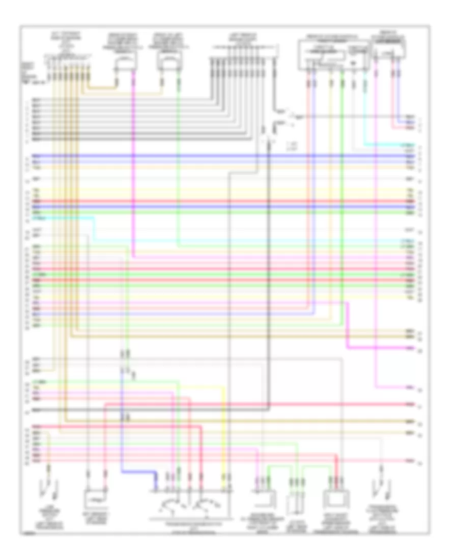
2.0L Hybrid, Engine Controls Wiring Diagram, Except Plug-In Hybrid (2 of 6) for Honda Accord Plug-In 2014
List of elements for 2.0L Hybrid, Engine Controls Wiring Diagram, Except Plug-In Hybrid (2 of 6) for Honda Accord Plug-In 2014:
- (left front of engine compt) j/c c012
- (lower right front of engine compt) a/c pressure sensor
- (right front of engine) evap canister purge valve 2
- (top of fuel tank) fuel tank unit
- A17
- A19
- A20
- C127
- C203
- C204
- C207
- Computer data lines system
- Dc-dc converter
- Etcs control relay
- F-can h
- F-can l
- F-can transceiver
- G502 (upper left end of dash)
- G602 (behind left rear seat)
- Gauge control module
- Indicator drive circuit
- Instrument cluster system
- Malfunction indicator lamp (mil)
- Pcu (top of traction/ generator motor assembly)
- Pgm-fi main relay 2
- Pnk
- Red
- Secondary ho2s (sensor 2) (in exhaust, downstream of catalytic converter)
- Stabilize circuit
- Tan
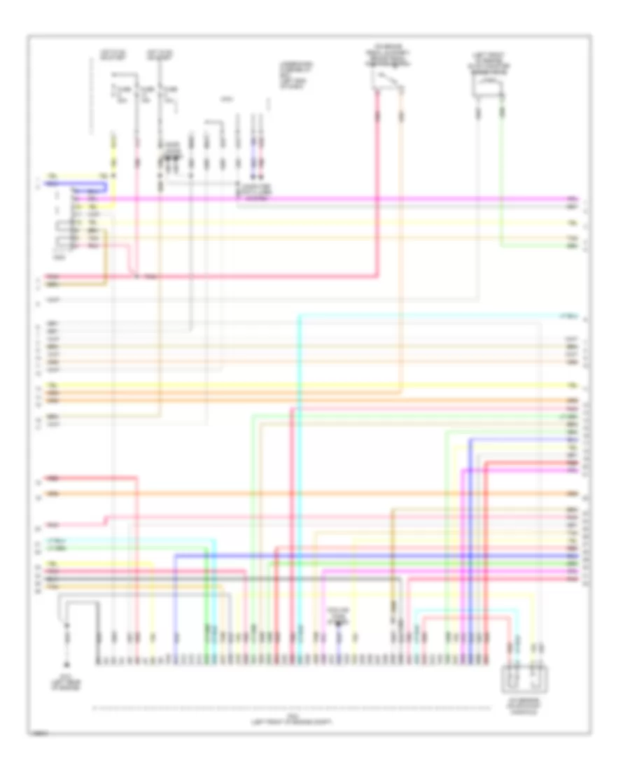
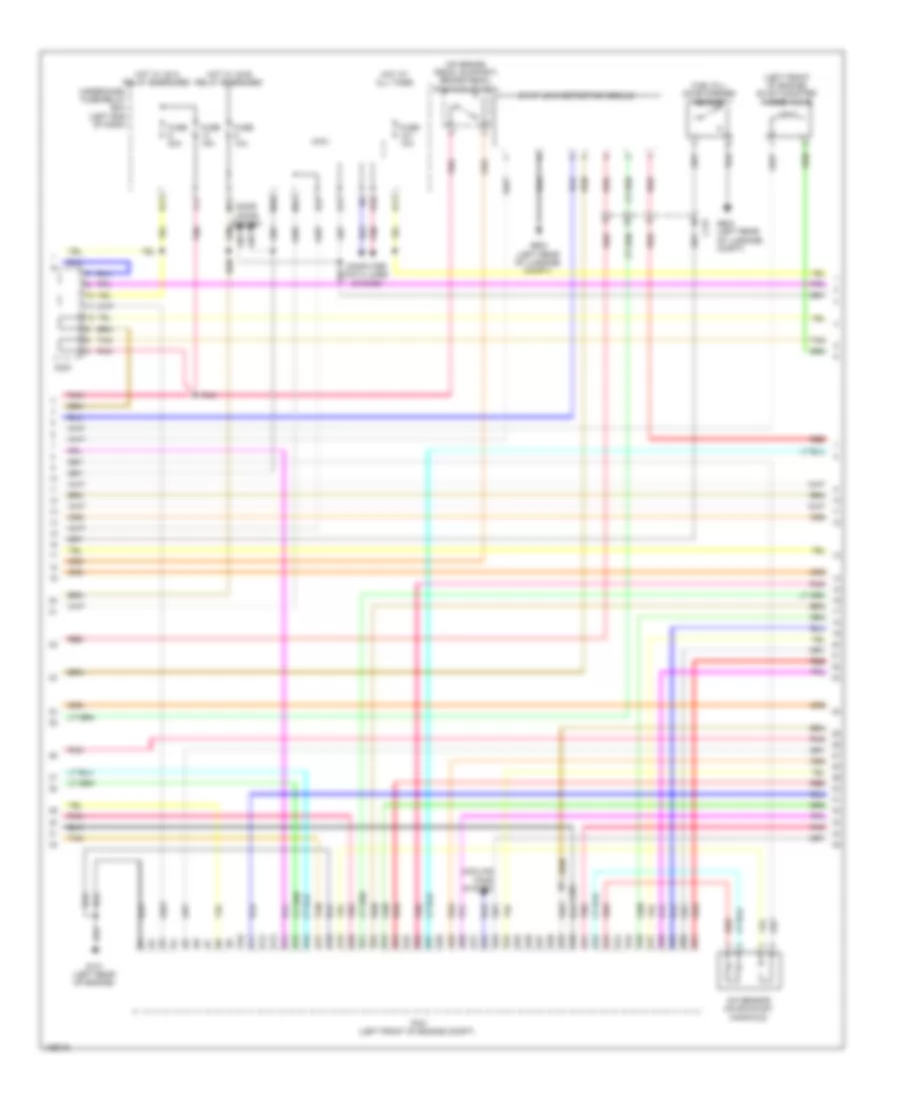
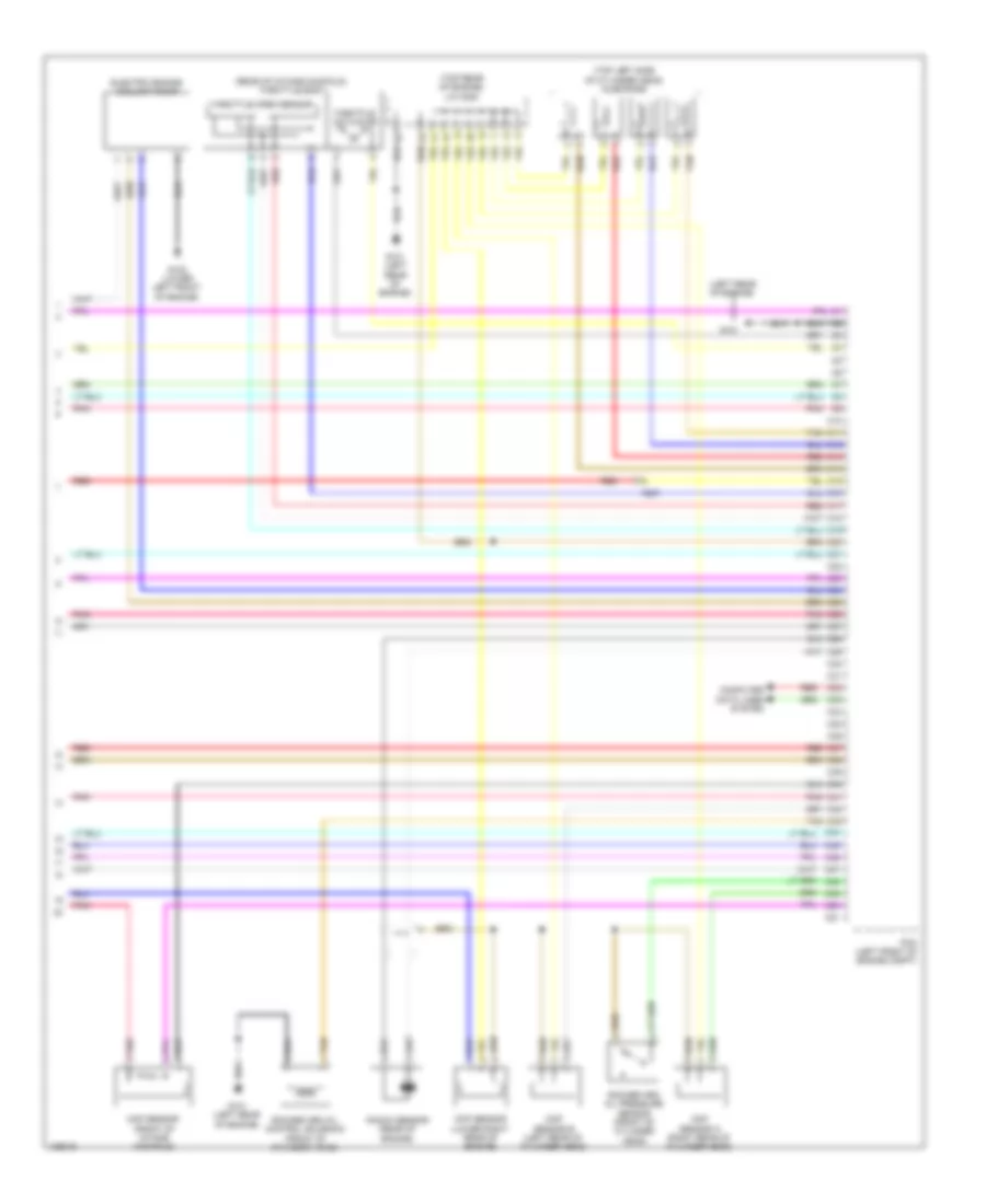
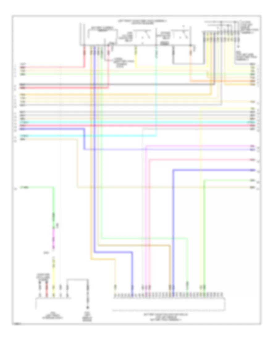
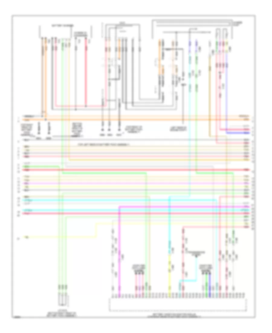
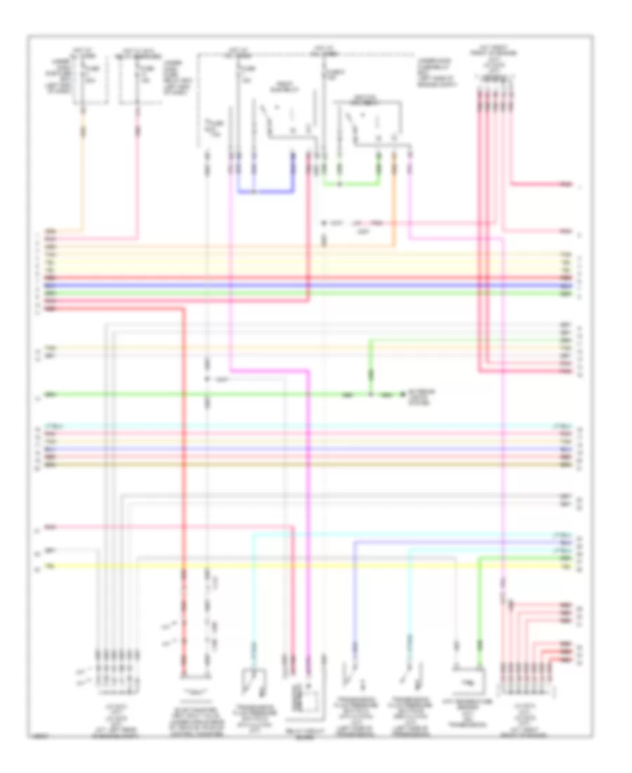
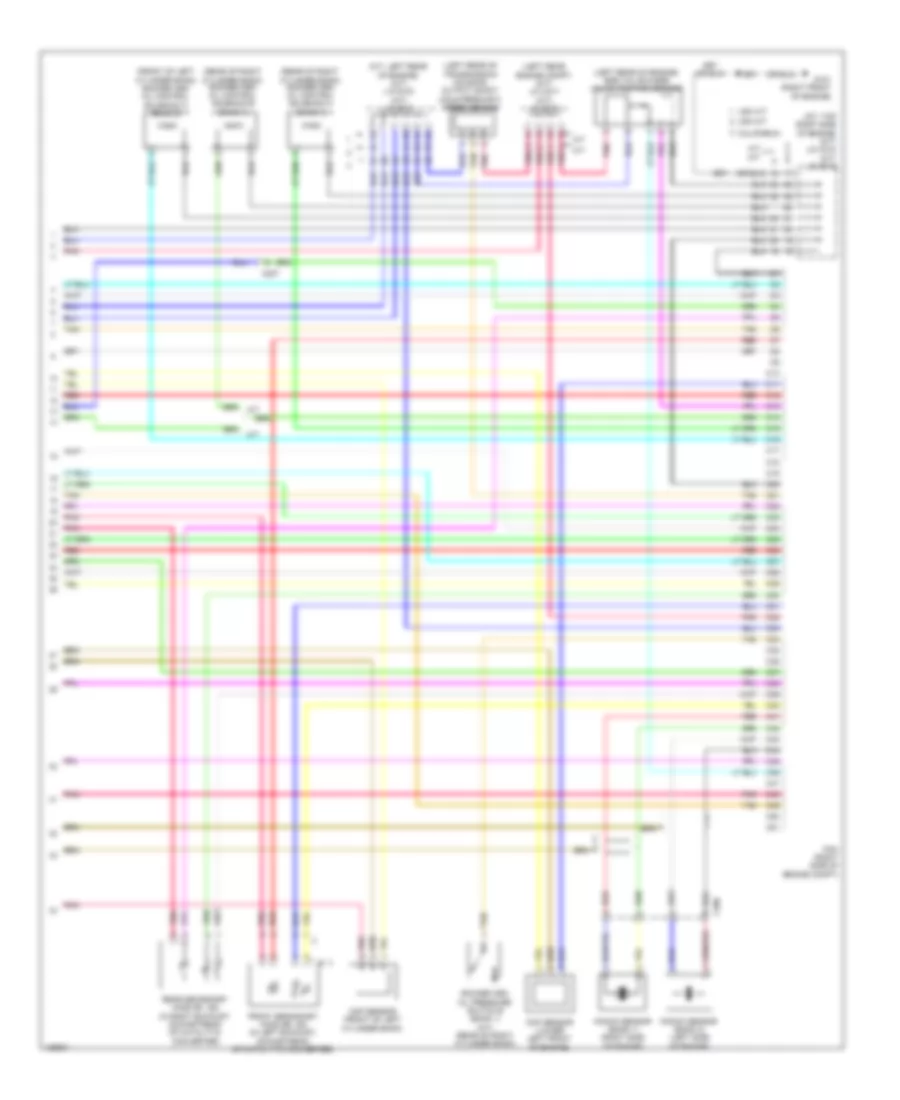
2.0L Hybrid, Engine Controls Wiring Diagram, Except Plug-In Hybrid (3 of 6) for Honda Accord Plug-In 2014
List of elements for 2.0L Hybrid, Engine Controls Wiring Diagram, Except Plug-In Hybrid (3 of 6) for Honda Accord Plug-In 2014:
- (left front of engine) evap canister purge valve
- (on brake pedal support) brake pedal position switch
- A/f sensor (on exhaust manifold)
- B10
- B11
- B12
- B13
- B14
- B15
- B16
- B17
- B18
- B19
- B20
- B21
- B22
- B23
- B24
- B25
- B26
- B27
- B28
- B29
- B30
- B31
- B32
- B33
- B34
- B35
- B36
- B37
- B38
- B39
- B40
- B41
- B42
- B43
- B44
- B45
- B46
- B47
- B48
- B49
- B50
- B51
- C201
- C203
- Computer data lines system
- Cooling fans system
- Door locks system
- E11
- E17
- E23
- F11
- Fuse 10a
- Fuse 15a
- Fuse 20a
- G101 (left rear of engine)
- Hot in on or start
- M10
- M11
- M12
- Micu
- Pcm (left front of engine compt)
- Pnk
- R10
- Red
- Tan
- Under-dash fuse/relay box (left end of dash)
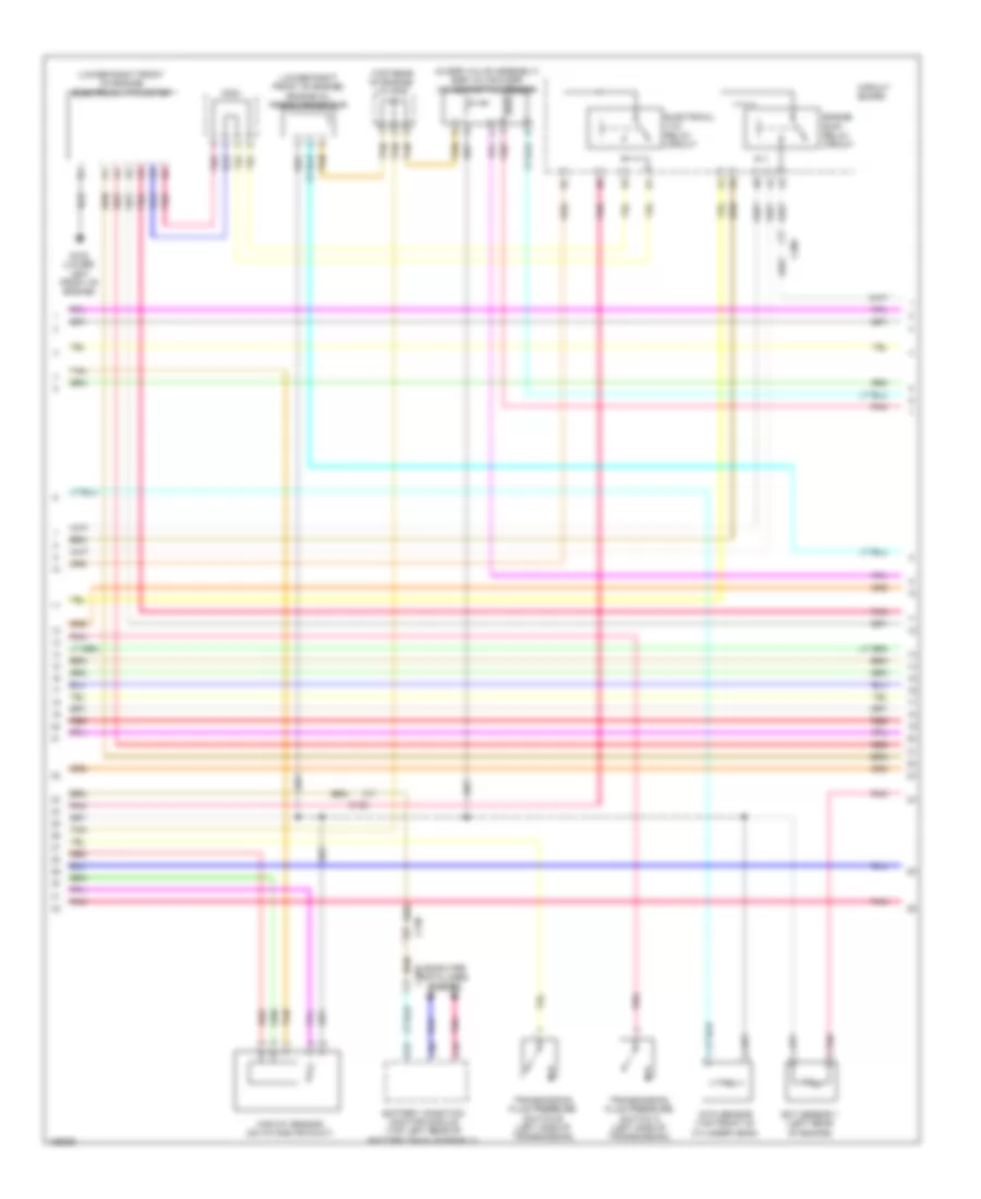
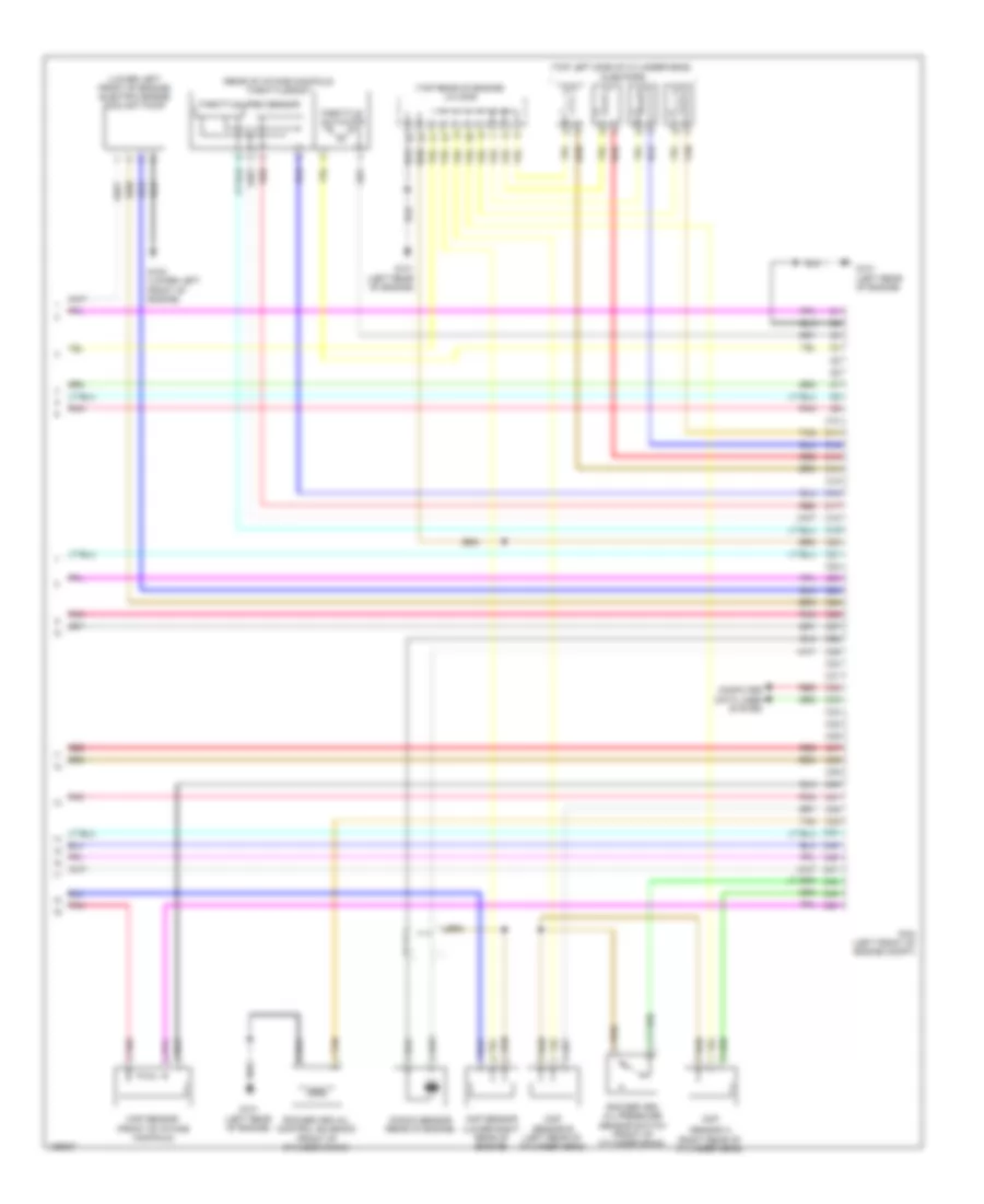
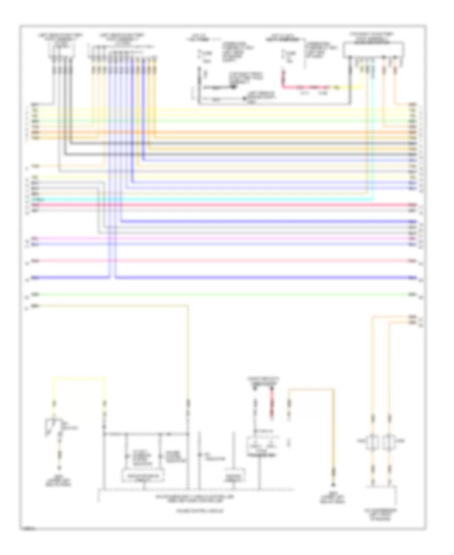
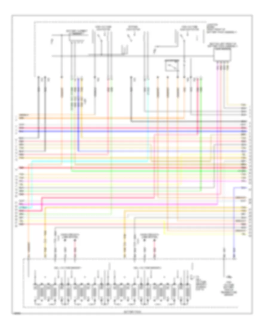
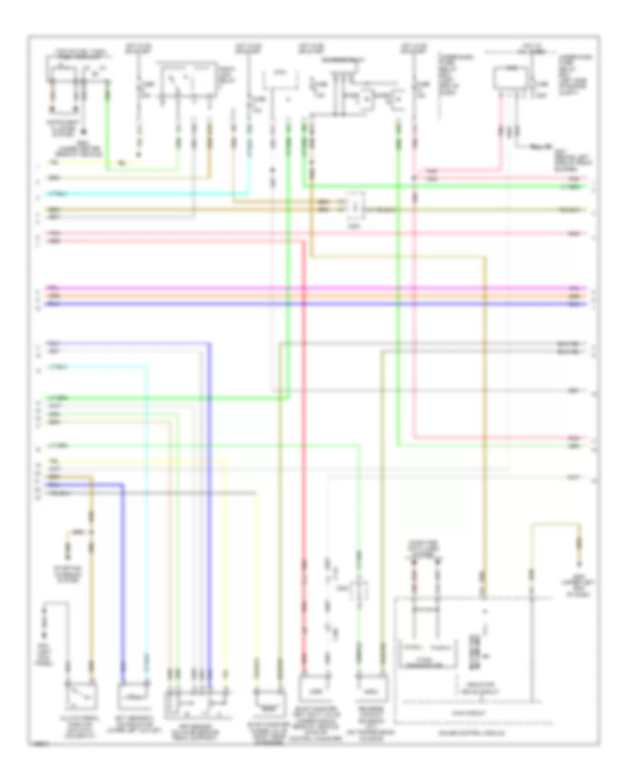
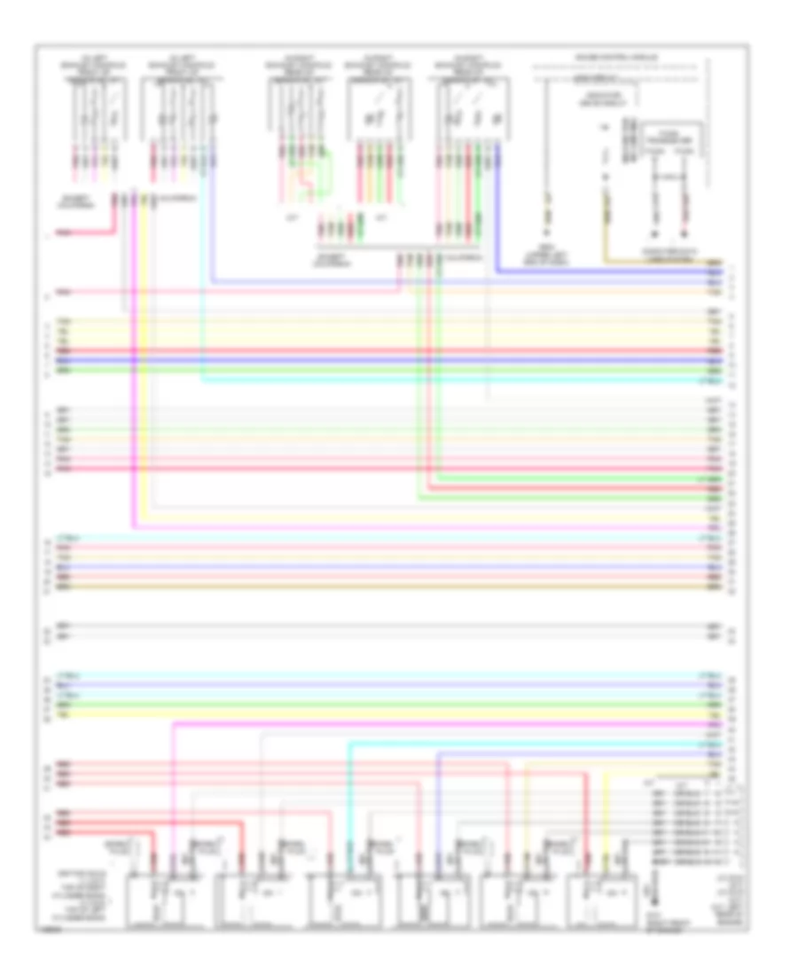
2.0L Hybrid, Engine Controls Wiring Diagram, Except Plug-In Hybrid (4 of 6) for Honda Accord Plug-In 2014
List of elements for 2.0L Hybrid, Engine Controls Wiring Diagram, Except Plug-In Hybrid (4 of 6) for Honda Accord Plug-In 2014:
- (in egr valve assembly) egr valve & egr valve position sensor
- (lower right front of engine) electrical vtc motor
- (lower right front of engine) engine oil pressure sensor
- (top rear of engine) j/c c005
- A13
- Battery condition monitor module (top left rear of battery pack assembly)
- C10
- C130
- C132
- C203
- C206
- C30
- C403
- Circuit board
- Computer data lines system
- Ect sensor 1 (left rear of engine)
- Electrical vtc relay circuit
- Engine ewp relay circuit
- G102 (lower left front of engine)
- Inta sensor (top front of cylinder head)
- Maf/iat sensor (on intake air duct)
- Pnk
- Red
- Tan
- Transmission fluid pressure switch a (left side of transmission)
- Transmission fluid pressure switch b (left side of transmission)
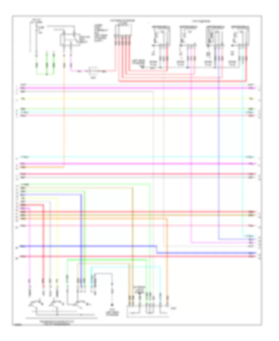
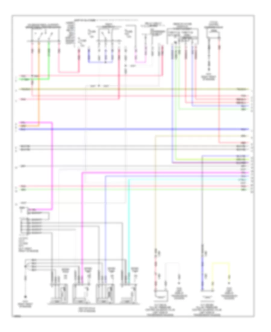
2.0L Hybrid, Engine Controls Wiring Diagram, Except Plug-In Hybrid (5 of 6) for Honda Accord Plug-In 2014
List of elements for 2.0L Hybrid, Engine Controls Wiring Diagram, Except Plug-In Hybrid (5 of 6) for Honda Accord Plug-In 2014:
- (left rear of engine) g101
- (top of engine)
- (top rear of engine) j/c c005
- C203
- Exterior lights system
- Fuse 15a
- Fwd
- Fwd2
- G101 (left rear of engine)
- Gnd
- Hot at all times
- Icm
- Ignition coil 1
- Ignition coil 2
- Ignition coil 3
- Ignition coil 4
- Ignition coil relay
- Pnk
- Red
- Rvs
- Rvs2
- Spark plug
- Transmission range switch (top of transmission)
- Under- hood fuse/relay box (left rear of engine compt)
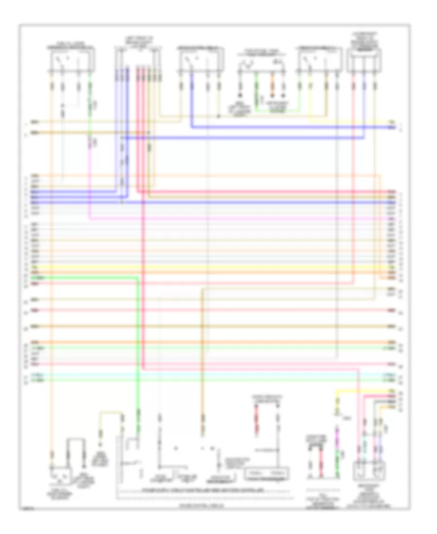
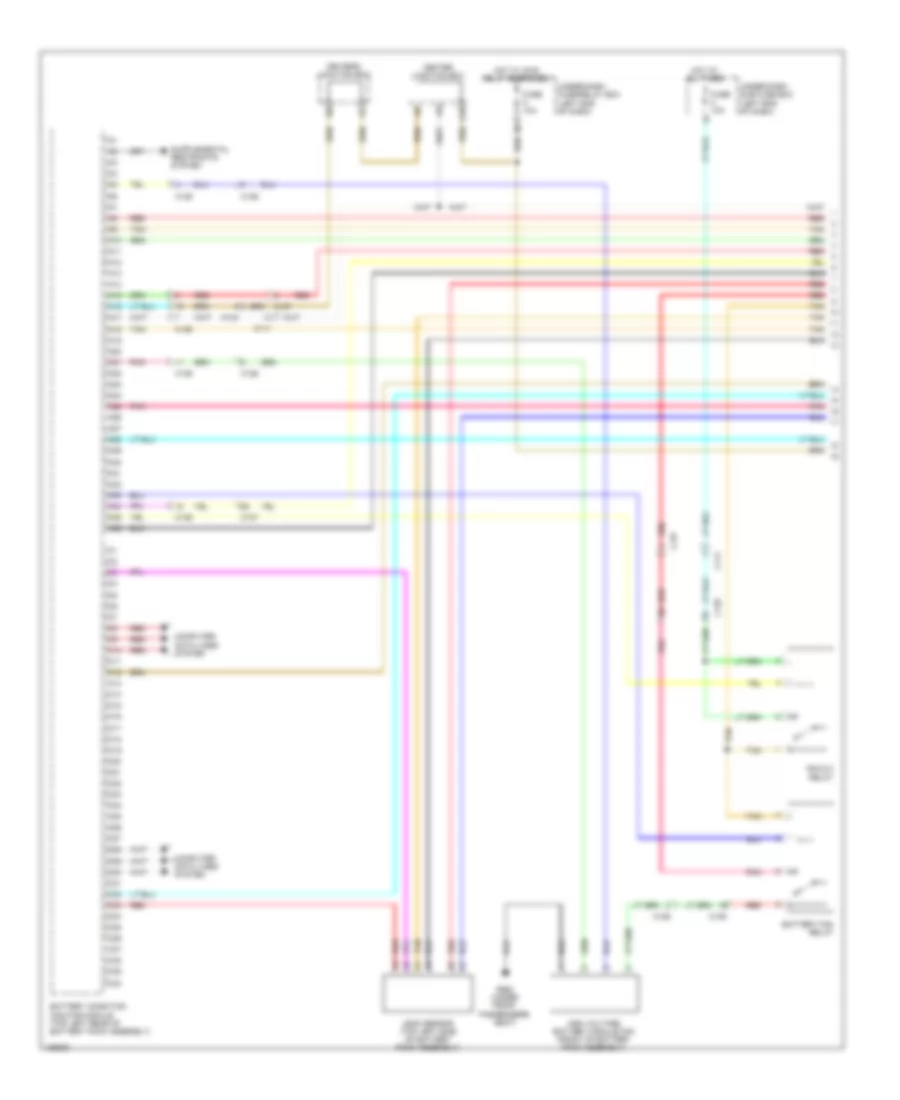
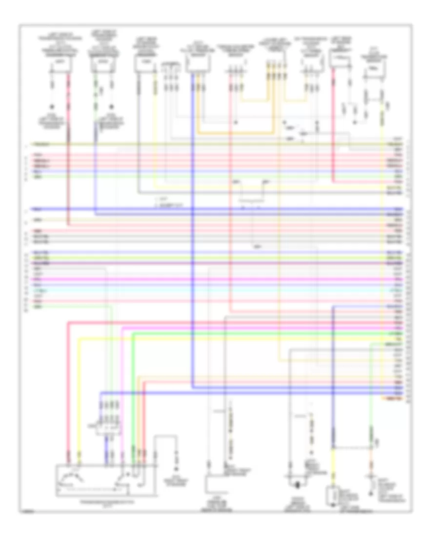
2.0L Hybrid, Engine Controls Wiring Diagram, Except Plug-In Hybrid (6 of 6) for Honda Accord Plug-In 2014
List of elements for 2.0L Hybrid, Engine Controls Wiring Diagram, Except Plug-In Hybrid (6 of 6) for Honda Accord Plug-In 2014:
- (lower left front of engine) electric engine coolant pump
- (rear of intake manifold) throttle body
- (right rear of cylinder head)
- (top left side of cylinder head) injectors
- (top rear of engine) j/c c005
- C10
- C11
- C12
- C13
- C14
- C15
- C16
- C17
- C18
- C19
- C20
- C21
- C22
- C23
- C24
- C25
- C26
- C27
- C28
- C29
- C30
- C31
- C32
- C33
- C34
- C35
- C36
- C37
- C38
- C39
- C40
- C41
- C42
- C43
- C44
- C45
- C46
- C47
- C48
- C49
- C50
- Ckp sensor (lower right rear of engine)
- Cmp
- Cmp sensor b (left rear of cylinder head)
- Computer data lines system
- G101 (left rear of engine)
- G102 (lower left front of engine)
- Knock sensor (rear of engine)
- Map sensor (front of intake manifold)
- Pcm (left front of engine compt)
- Pnk
- Red
- Rocker arm oil control solenoid (front of cylinder bank)
- Rocker arm oil pressure sensor switch (front of cylinder bank)
- Sensor a
- Tan
- Throttle actuator
- Throttle open sensor
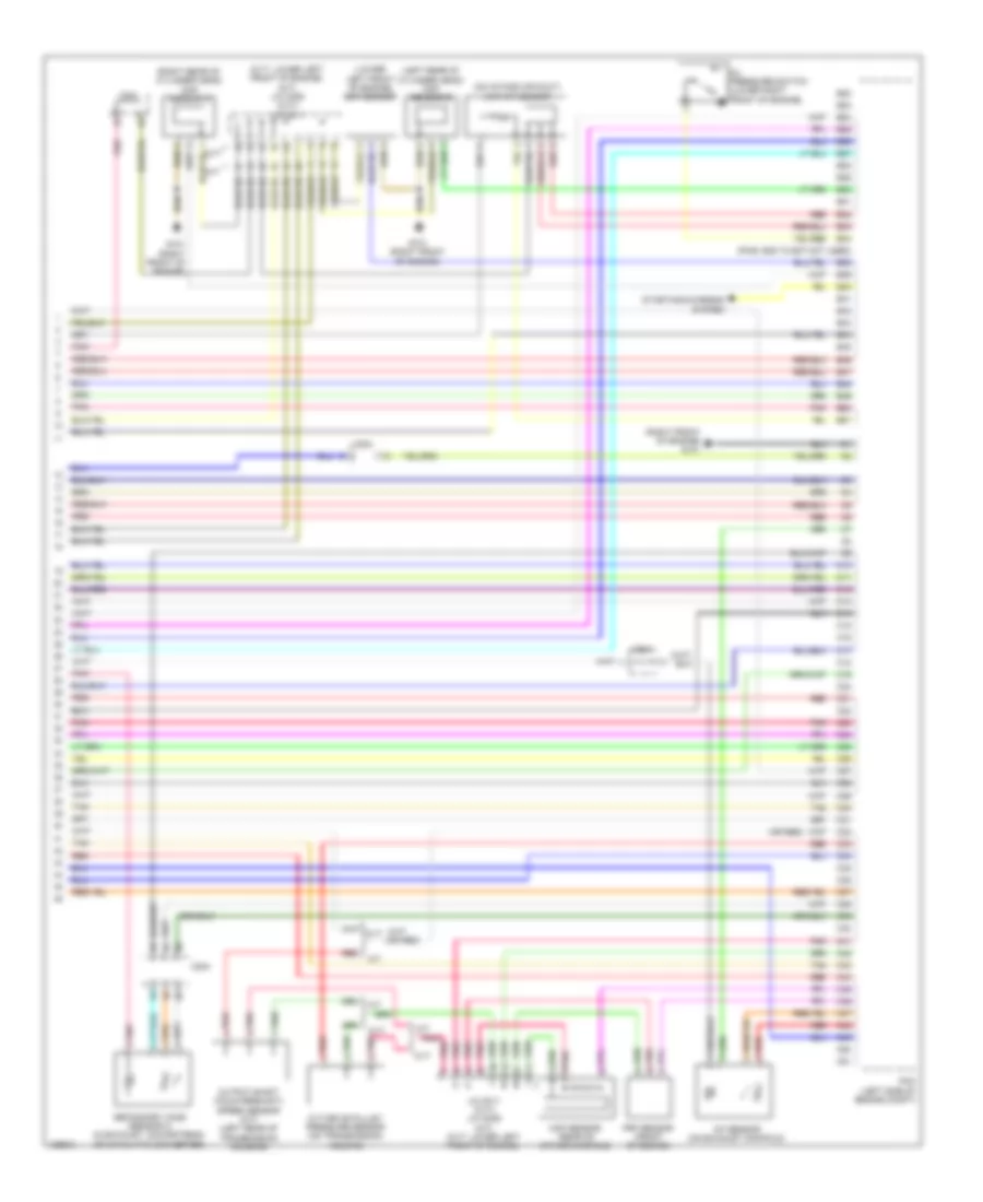
2.0L Hybrid, Engine Controls Wiring Diagram, Plug-In Hybrid (1 of 6) for Honda Accord Plug-In 2014
List of elements for 2.0L Hybrid, Engine Controls Wiring Diagram, Plug-In Hybrid (1 of 6) for Honda Accord Plug-In 2014:
- A10
- A11
- A12
- A13
- A14
- A15
- A16
- A17
- A18
- A19
- A20
- A21
- A22
- A23
- A24
- A25
- A26
- A27
- A28
- A29
- A30
- A31
- A32
- A33
- A34
- A35
- A36
- A37
- A38
- A39
- A40
- A41
- A42
- A43
- A44
- A45
- A46
- A47
- A48
- A49
- A50
- A51
- Anti-lock brakes system
- App sensor (on accelerator pedal support)
- App sensor a
- App sensor b
- C113
- C131
- C203
- Computer data lines system
- Cooling fans system
- Door locks system
- Ect sensor 2 (on radiator lower left outlet)
- Ftp sensor
- Fuel vapor containment valve
- Fuse 10a
- Fuse 15a
- Fuse 2-3 20a
- Fuse 20a
- Fuse 7.5a
- G101 (left rear of engine)
- Hot at all times
- Hot w/ rfc relay energized
- Navigation & sound systems
- Pcm (left front of engine compt)
- Pgm-fi main relay 1
- Pgm-fi sub relay
- Pnk
- Red
- Shift interlock system
- Shift solenoid valve a (left side of transmission)
- Shift solenoid valve b (left side of transmission)
- Under- hood fuse/ relay box (left rear of engine compt)
2.0L Hybrid, Engine Controls Wiring Diagram, Plug-In Hybrid (2 of 6) for Honda Accord Plug-In 2014
List of elements for 2.0L Hybrid, Engine Controls Wiring Diagram, Plug-In Hybrid (2 of 6) for Honda Accord Plug-In 2014:
- (left front of engine compt) j/c c007
- (lower right front of engine compt) a/c pressure sensor
- (top of fuel tank) fuel tank unit
- (upper left end of dash)
- A17
- A19
- A20
- B12
- C131
- C132
- C201
- C203
- C207
- Computer data lines system
- Dc-dc converter
- Etcs control relay
- F-can h
- F-can l
- F-can transceiver
- Fuel fill door opener solenoid
- Fuel fill door opener solenoid relay
- G502
- G602 (left front of luggage compt)
- G603 (left rear of luggage compt)
- Gauge control module
- Indicator drive circuit
- Instrument cluster system
- Malfunction indicator lamp (mil)
- Pcu (top of traction/ generator motor assembly)
- Pgm-fi main relay 2
- Pnk
- Red
- Secondary ho2s (sensor 2) (in exhaust, downstream of catalytic converter)
- Stabilize circuit
- Tan
2.0L Hybrid, Engine Controls Wiring Diagram, Plug-In Hybrid (3 of 6) for Honda Accord Plug-In 2014
List of elements for 2.0L Hybrid, Engine Controls Wiring Diagram, Plug-In Hybrid (3 of 6) for Honda Accord Plug-In 2014:
- (left front of engine) evap canister purge valve
- (on brake pedal support) brake pedal position switch
- A/f sensor (on exhaust manifold)
- B10
- B11
- B12
- B13
- B14
- B15
- B16
- B17
- B18
- B19
- B20
- B21
- B22
- B23
- B24
- B25
- B26
- B27
- B28
- B29
- B30
- B31
- B32
- B33
- B34
- B35
- B36
- B37
- B38
- B39
- B40
- B41
- B42
- B43
- B44
- B45
- B46
- B47
- B48
- B49
- B50
- B51
- C131
- C201
- C203
- Computer data lines system
- Cooling fans system
- Door locks system
- E11
- E17
- E23
- Evap leak detection module
- F11
- Fuel fill door opener sensor
- Fuse 10a
- Fuse 15a
- Fuse 18-1 10a
- Fuse 20a
- G101 (left rear of engine)
- G603 (left rear of luggage compt)
- Hot at all times
- Hot w/ ig1a relay energized
- Hot w/ ig1b relay energized
- M10
- M11
- M12
- Micu
- Pcm (left front of engine compt)
- Pnk
- R10
- R11
- Red
- Tan
- Under-dash fuse/relay box (left end of dash)
2.0L Hybrid, Engine Controls Wiring Diagram, Plug-In Hybrid (4 of 6) for Honda Accord Plug-In 2014
List of elements for 2.0L Hybrid, Engine Controls Wiring Diagram, Plug-In Hybrid (4 of 6) for Honda Accord Plug-In 2014:
- (egr valve: left side of engine) (egr valve position sensor: on egr valve assembly) egr valve & egr valve position sensor
- (lower right front of engine) electrical vtc motor
- (lower right front of engine) engine oil pressure sensor
- (top rear of engine) j/c c006
- A13
- Battery condition monitor module (top right rear of battery pack assembly)
- C10
- C104
- C130
- C132
- C201
- C202
- C203
- C30
- C403
- Circuit board
- Computer data lines system
- Ect sensor 1 (left rear of engine)
- Electrical vtc relay circuit
- Engine ewp relay circuit
- Fuel fill door opener switch
- G101 (left rear of engine)
- Inta sensor (top front of cylinder head)
- Maf/iat sensor (on intake air duct)
- Pnk
- Red
- Tan
- Transmission fluid pressure switch a (left side of transmission)
- Transmission fluid pressure switch b (left side of transmission)
2.0L Hybrid, Engine Controls Wiring Diagram, Plug-In Hybrid (5 of 6) for Honda Accord Plug-In 2014
List of elements for 2.0L Hybrid, Engine Controls Wiring Diagram, Plug-In Hybrid (5 of 6) for Honda Accord Plug-In 2014:
- (left rear of engine) g101
- (top of engine) ignition coil 1
- (top of engine) ignition coil 2
- (top of engine) ignition coil 3
- (top of engine) ignition coil 4
- (top rear of engine) j/c c006
- C203
- Exterior lights system
- Fuse 15a
- Fwd
- Fwd2
- G101 (left rear of engine)
- Gnd
- Hot at all times
- Icm
- Ignition coil relay
- Pnk
- Red
- Rvs
- Rvs2
- Spark plug
- Transmission range switch (top of transmission)
- Under- hood fuse/relay box (left end of dash)
2.0L Hybrid, Engine Controls Wiring Diagram, Plug-In Hybrid (6 of 6) for Honda Accord Plug-In 2014
List of elements for 2.0L Hybrid, Engine Controls Wiring Diagram, Plug-In Hybrid (6 of 6) for Honda Accord Plug-In 2014:
- (left rear of engine)
- (rear of intake manifold) throttle body
- (top left side of cylinder head) injectors
- (top rear of engine) j/c c006
- C10
- C11
- C12
- C13
- C14
- C15
- C16
- C17
- C18
- C19
- C20
- C201
- C21
- C22
- C23
- C24
- C25
- C26
- C27
- C28
- C29
- C30
- C31
- C32
- C33
- C34
- C35
- C36
- C37
- C38
- C39
- C40
- C41
- C42
- C43
- C44
- C45
- C46
- C47
- C48
- C49
- C50
- C51
- Ckp sensor (lower right rear of engine)
- Cmp sensor a (right rear of cylinder head)
- Cmp sensor b (left rear of cylinder head)
- Computer data lines system
- Electric engine coolant pump
- G101
- G101 (left rear of engine)
- G102 (lower left front of engine)
- Knock sensor (rear of engine)
- Map sensor (front of intake manifold)
- Pcm (left front of engine compt)
- Pnk
- Red
- Rocker arm oil control solenoid (front of cylinder head)
- Rocker arm oil pressure sensor (front of cylinder head)
- Tan
- Throttle actuator
- Throttle open sensor
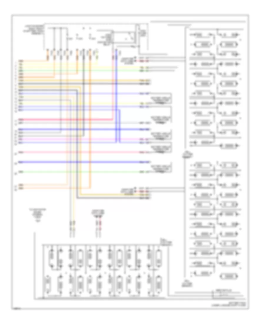
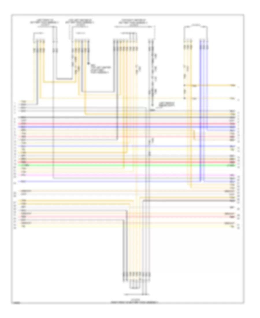
2.0L Hybrid, Hybrid System Wiring Diagram, Except Plug-In Hybrid (1 of 6) for Honda Accord Plug-In 2014
List of elements for 2.0L Hybrid, Hybrid System Wiring Diagram, Except Plug-In Hybrid (1 of 6) for Honda Accord Plug-In 2014:
- A10
- A11
- A12
- A13
- A14
- A15
- A16
- A17
- A18
- A19
- A20
- A21
- A22
- A23
- A24
- A25
- A26
- A27
- A28
- A29
- A30
- A31
- A32
- A33
- A34
- A35
- A36
- Battery condition monitor module (top left rear of battery pack assembly)
- Battery fan relay
- C10
- C104
- C11
- C111
- C12
- C126
- C127
- C129
- C13
- C14
- C15
- C16
- C17
- C18
- C19
- C20
- C21
- C22
- C23
- C24
- C25
- C26
- C27
- C28
- C29
- C30
- C31
- C32
- C33
- C34
- C35
- C36
- C37
- C38
- C39
- C40
- Center junction box
- Computer data lines system
- Driver's junction box
- Fuse 10a
- G652 (under front passenger's seat)
- High voltage battery module fan (front of battery pack assembly)
- Hot at all times
- Hot w/ ig1b relay energized
- Ighld 2 relay
- Leak sensor (top left side of battery pack assembly)
- M11
- Pnk
- Red
- Tan
- Under-dash fuse/relay box (left end of dash)
- Under-dash sub fuse box (left end of dash)
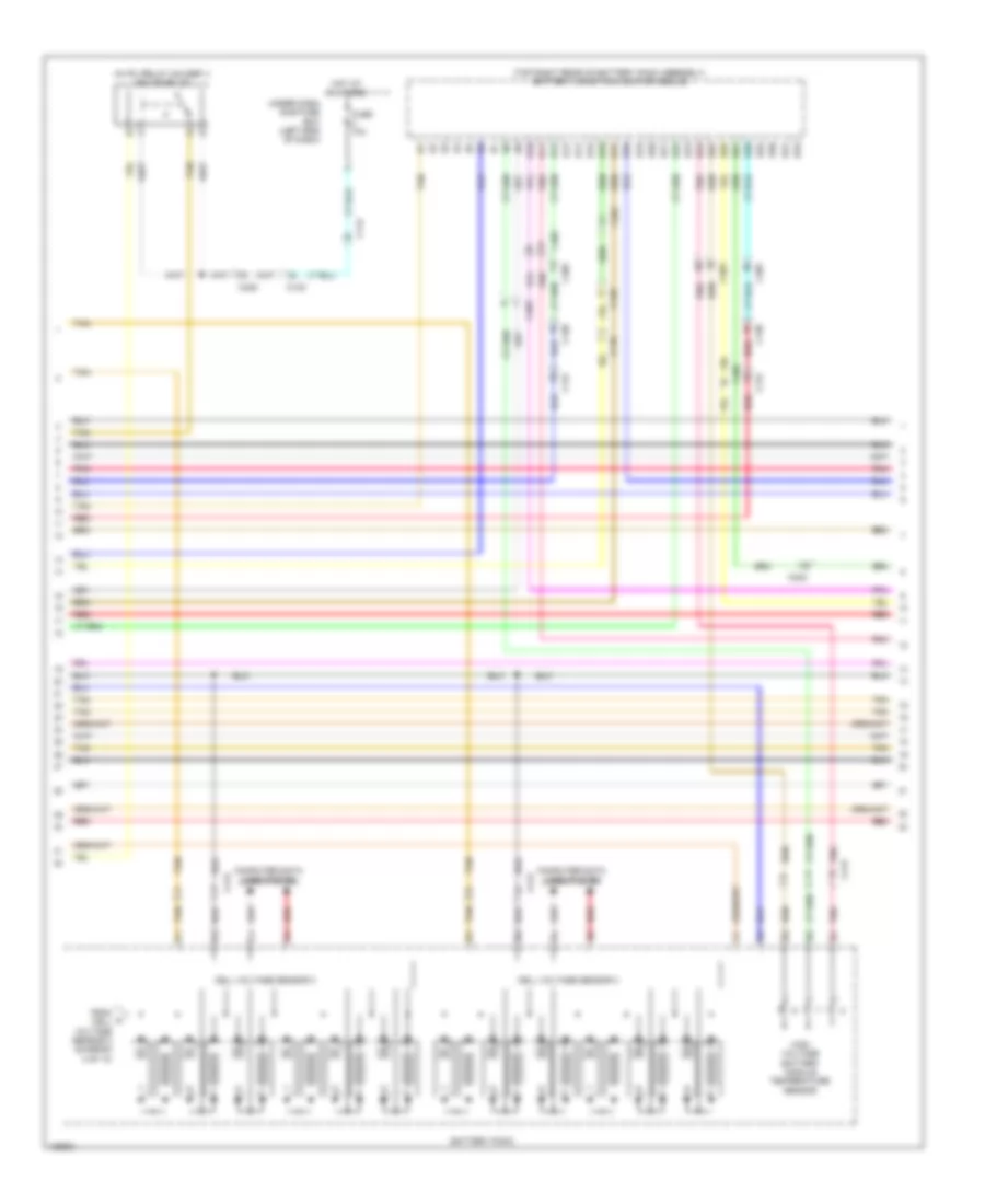
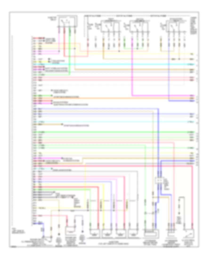
2.0L Hybrid, Hybrid System Wiring Diagram, Except Plug-In Hybrid (2 of 6) for Honda Accord Plug-In 2014
List of elements for 2.0L Hybrid, Hybrid System Wiring Diagram, Except Plug-In Hybrid (2 of 6) for Honda Accord Plug-In 2014:
- (behind left side of front bumper) g301
- (left side of traction/ generator motor assembly) j/c c004
- Air conditioning system
- B10
- C205
- Computer data lines system
- E23
- Fuse 10a
- Gate driver board
- Generator phase current sensor
- Hot at all times
- Ighld1 relay circuit
- Ipin
- Motor control module
- Motor phase current sensor
- Mpi module
- Pcu (top of traction/generator motor assembly)
- Pnk
- Power distribution system
- Reactor temperature sensor
- Red
- Relay circuit board
- T10
- Tan
- Under-dash fuse/relay box (left end of dash)
- Under-hood fuse/relay box (left rear of engine compt)
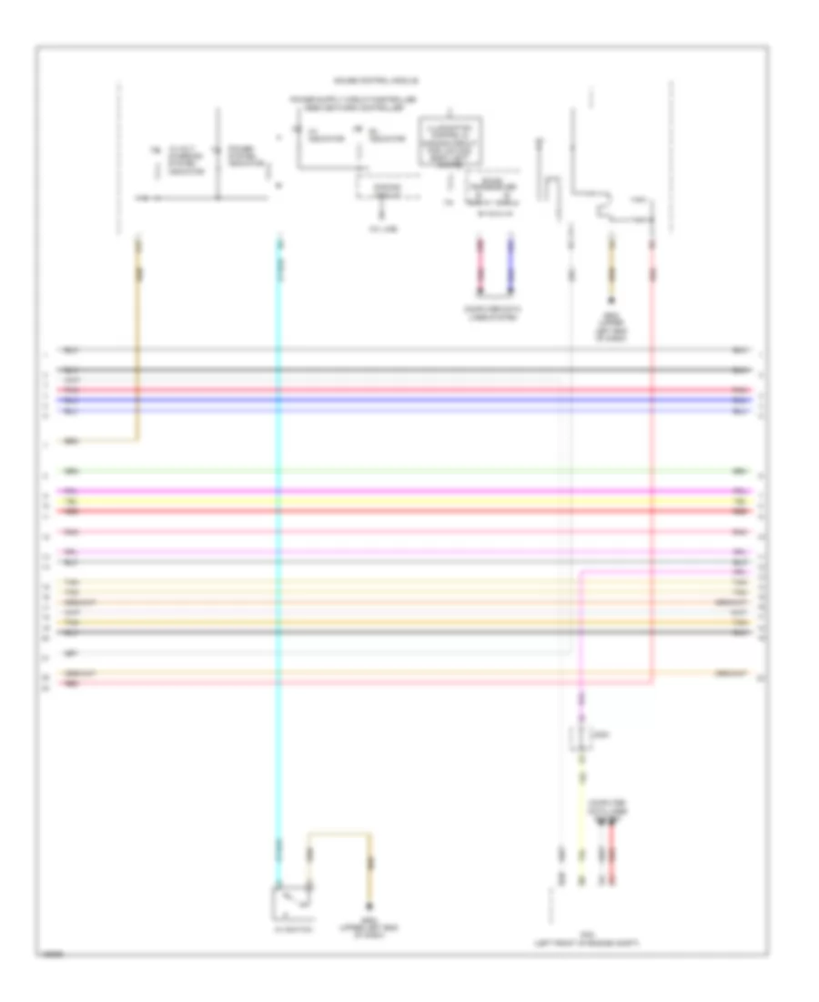
2.0L Hybrid, Hybrid System Wiring Diagram, Except Plug-In Hybrid (3 of 6) for Honda Accord Plug-In 2014
List of elements for 2.0L Hybrid, Hybrid System Wiring Diagram, Except Plug-In Hybrid (3 of 6) for Honda Accord Plug-In 2014:
- (left front of engine compt) j/c c012
- (left side of traction/ generator motor assembly) j/c c004
- C205
- C207
- C401
- C402
- C403
- Electric powertrain coolant temperature sensor (bottom left of radiator)
- Fuse 10a
- Fuse 15a
- Generator motor
- Generator motor rotor position sensor
- Generator motor temperature sensor
- Hot at all times
- Motor assembly
- Pnk
- Red
- Tan
- Traction motor
- Traction motor rotor position sensor
- Traction motor temperature sensor
- Transmission fluid temperature sensor (bottom rear of transmission housing)
- Under-hood fuse/relay box (left rear of engine compt)
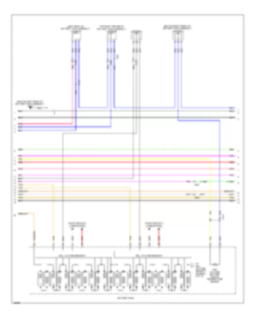
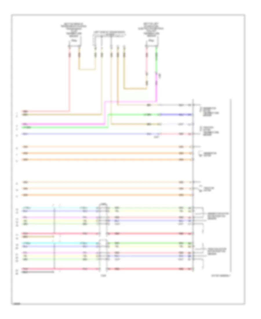
2.0L Hybrid, Hybrid System Wiring Diagram, Except Plug-In Hybrid (4 of 6) for Honda Accord Plug-In 2014
List of elements for 2.0L Hybrid, Hybrid System Wiring Diagram, Except Plug-In Hybrid (4 of 6) for Honda Accord Plug-In 2014:
- (diagram 6 of 6)
- (left front of battery pack assembly) contactor board
- B10
- B11
- B12
- B13
- B14
- B15
- B16
- B17
- B18
- B19
- B20
- B21
- B22
- B23
- B24
- B25
- B26
- B27
- B28
- B29
- B30
- B31
- B32
- Battery condition monitor module (top left rear of battery pack assembly)
- Battery current sensor
- Bypass contactor relay
- C203
- C207
- Computer data lines system
- From battery pack a
- G101 (left rear of engine)
- G801 (top left side of battery pack assembly)
- High voltage contactor relay
- J/c c003 (top left side of battery pack assembly)
- Pcm (left front of engine compt)
- Pnk
- Red
- T131
- T152
- Tan
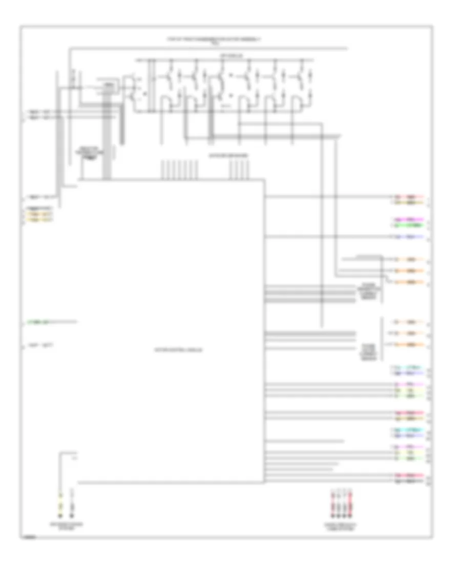
2.0L Hybrid, Hybrid System Wiring Diagram, Except Plug-In Hybrid (5 of 6) for Honda Accord Plug-In 2014
List of elements for 2.0L Hybrid, Hybrid System Wiring Diagram, Except Plug-In Hybrid (5 of 6) for Honda Accord Plug-In 2014:
- (left rear of battery pack assembly) j/c c001
- (left rear of battery pack assembly) j/c c002
- (left rear of engine compt) g351
- (top right front of battery pack assembly) g655
- (top right of battery pack assembly) dc-dc converter
- 12 volt charging system indicator
- A/c compressor (left front of engine)
- A17
- A19
- A20
- C111
- C129
- C404
- C405
- Computer data lines system
- Dimming circuit
- Ev indicator
- Ev switch
- F- can h
- F- can l
- F-can transceiver
- Fuse 150a
- Fuse 15a
- G502 (upper left end of dash)
- Gauge control module
- Hot at all times
- Hot w/ ig1a relay energized
- Indicator drive circuit
- Pnk
- Power system indicator
- Red
- T101
- T122
- T141
- T142
- Tan
- Under-dash fuse/relay box (left end of dash)
- Under-hood fuse/relay box (left rear of engine compt)
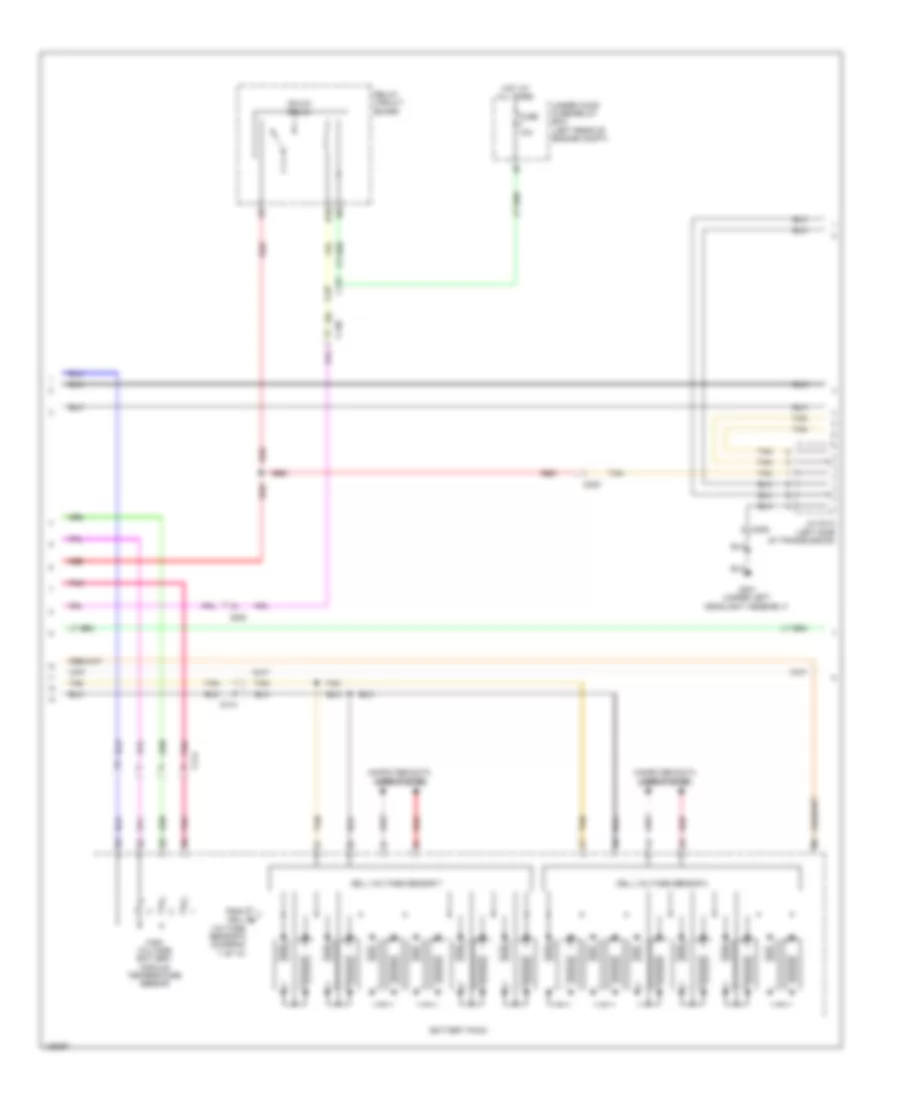
2.0L Hybrid, Hybrid System Wiring Diagram, Except Plug-In Hybrid (6 of 6) for Honda Accord Plug-In 2014
List of elements for 2.0L Hybrid, Hybrid System Wiring Diagram, Except Plug-In Hybrid (6 of 6) for Honda Accord Plug-In 2014:
- 30a
- Battery module temperature sensor 1
- Battery module temperature sensor 2
- Battery module temperature sensor 3
- Battery module temperature sensor 4
- Battery module temperature sensor 5
- Battery pack (under luggage compt floor)
- Cell voltage sensor 1
- Cell voltage sensor 2
- Cell voltage sensor 3
- Computer data lines system
- High voltage sub contactor relay
- Junction board (right front of battery pack assembly)
- Main fuse 200a
- Pnk
- Red
- Service plug
- T123
- T124
- T132
- T143
- T144
- T151
- T181
- T182
- Tan
- To contactor board (diagram 4 of 6)
2.0L Hybrid, Hybrid System Wiring Diagram, Plug-In Hybrid (1 of 10) for Honda Accord Plug-In 2014
List of elements for 2.0L Hybrid, Hybrid System Wiring Diagram, Plug-In Hybrid (1 of 10) for Honda Accord Plug-In 2014:
- (left front of battery pack assembly)
- (top right front of battery pack assembly)
- (top right of battery pack assembly) dc-dc converter
- A10
- A11
- A12
- A13
- A14
- A15
- A16
- A17
- A18
- A19
- A20
- A21
- A22
- A23
- A24
- A25
- A26
- A27
- A28
- A29
- A30
- A31
- A32
- A33
- A34
- A35
- A36
- Air conditioning system
- Battery condition monitor module (top right rear of battery pack assembly)
- C104
- C111
- C119
- C126
- C130
- C131
- C132
- C201
- C206
- C401
- C403
- C404
- C405
- Center junction box
- Charge lid actuator (left end of dash)
- Charge lid illumination lamp switch
- Charge lid illumination lamp/charge indicator
- Charge lid illumination lamp/charge indicator relay (in under-dash fuse/relay box b)
- Charge lid opener switch
- Cooling fans system
- Drive's junction box
- E23
- Fuse 10a
- Fuse 150a
- Fuse 18-1 10a
- G301 (under left headlight assembly)
- G351 (left rear of engine compt)
- G401 (left kick panel)
- G502 (upper left end of dash)
- G655 (bottom left front of battery pack assembly)
- G804
- G805
- Hot at all times
- J/c c007 (left front of engine compt)
- M11
- Micu
- P16
- P20
- P21
- Pnk
- R11
- Red
- T101
- T65
- T66
- T71
- Tan
- Under dash fuse/relay box (left end of dash)
- Under hood fuse/relay box (left rear of engine compt)
2.0L Hybrid, Hybrid System Wiring Diagram, Plug-In Hybrid (2 of 10) for Honda Accord Plug-In 2014
List of elements for 2.0L Hybrid, Hybrid System Wiring Diagram, Plug-In Hybrid (2 of 10) for Honda Accord Plug-In 2014:
- (bottom center front of battery pack assembly)
- (left rear of engine compt)
- (top front of battery pack assembly)
- (top left rear of battery pack assembly)
- (top right front of battery pack assembly)
- Battery charger
- Battery condition monitor module (top right rear of battery pack assembly)
- C10
- C11
- C118
- C12
- C126
- C13
- C130
- C131
- C132
- C14
- C15
- C16
- C17
- C18
- C19
- C20
- C206
- C21
- C22
- C23
- C24
- C25
- C26
- C27
- C28
- C29
- C30
- C31
- C32
- C33
- C34
- C35
- C36
- C37
- C38
- C39
- C40
- C401
- C403
- C405
- C406
- C410
- Charge ac condenser
- Charge inlet
- Computer data lines system
- G532
- G656
- G802
- G803
- G804
- J/c c015 (bottom right front of battery pack assembly)
- Pnk
- Red
- T11
- T12
- T13
- T14
- T61
- T63
- Tan
- Transmissions system
2.0L Hybrid, Hybrid System Wiring Diagram, Plug-In Hybrid (3 of 10) for Honda Accord Plug-In 2014
List of elements for 2.0L Hybrid, Hybrid System Wiring Diagram, Plug-In Hybrid (3 of 10) for Honda Accord Plug-In 2014:
- (bottom left front of battery pack assembly) leak sensor
- Battery current sensor
- Battery pack
- Bypass contactor
- C401
- C411
- Cell voltage sensor 1
- Cell voltage sensor 2
- Computer data lines system
- High voltage battery module temperature sensor
- High voltage contactor
- High voltage sub contactor
- Junction board (right front of battery pack assembly)
- Main switch
- Pnk
- Red
- T51
- T52
- T57
- T62
- T64
- T72
- Tan
- To cell voltage sensor 3 (diagram 5 of 10)
2.0L Hybrid, Hybrid System Wiring Diagram, Plug-In Hybrid (4 of 10) for Honda Accord Plug-In 2014
List of elements for 2.0L Hybrid, Hybrid System Wiring Diagram, Plug-In Hybrid (4 of 10) for Honda Accord Plug-In 2014:
- (left front of battery pack assembly) j/c c017
- (left rear of engine compt)
- (top left center of battery pack assembly) j/c c012
- (top right center of battery pack assembly) j/c c010
- C130
- C131
- C206
- C401
- C403
- C404
- C405
- C413
- G532
- G801 (top left center of battery pack assembly)
- J/c c014
- J/c c016 (right front of battery pack assembly)
- Pnk
- Red
- Tan
2.0L Hybrid, Hybrid System Wiring Diagram, Plug-In Hybrid (5 of 10) for Honda Accord Plug-In 2014
List of elements for 2.0L Hybrid, Hybrid System Wiring Diagram, Plug-In Hybrid (5 of 10) for Honda Accord Plug-In 2014:
- (in ipu relay holder 1) ighldb relay
- (top right rear of battery pack assembly) battery condition monitor module
- B10
- B11
- B12
- B13
- B14
- B15
- B16
- B17
- B18
- B19
- B20
- B21
- B22
- B23
- B24
- B25
- B26
- B27
- B28
- B29
- B30
- B31
- B32
- Battery pack
- C112
- C118
- C126
- C130
- C131
- C401
- C402
- C403
- C405
- C412
- C413
- Cell voltage sensor 3
- Cell voltage sensor 4
- Computer data lines system
- From a cell voltage sensor 2 (diagram 3 of 10)
- Fuse 10a
- High voltage battery module temperature sensor
- Hot at all times
- Pnk
- Red
- Tan
- Under dash sub fuse box (left end of dash)
2.0L Hybrid, Hybrid System Wiring Diagram, Plug-In Hybrid (6 of 10) for Honda Accord Plug-In 2014
List of elements for 2.0L Hybrid, Hybrid System Wiring Diagram, Plug-In Hybrid (6 of 10) for Honda Accord Plug-In 2014:
- 10v line
- 12 volt charging system indicator
- A17
- A30
- A31
- B- can h
- B- can l
- B-can transceiver
- B39
- C203
- Computer data lines system
- Dimming circuit
- Ev indicator
- G502 (upper left end of dash)
- Gauge control module
- Hv indicator
- Hv switch
- Illumination control & dimming circuit for lcd (mid) back light (white)
- Pcm (left front of engine compt)
- Pnk
- Power system indicator
- Red
- Tan
2.0L Hybrid, Hybrid System Wiring Diagram, Plug-In Hybrid (7 of 10) for Honda Accord Plug-In 2014
List of elements for 2.0L Hybrid, Hybrid System Wiring Diagram, Plug-In Hybrid (7 of 10) for Honda Accord Plug-In 2014:
- (bottom left front of battery pack assembly) g655
- (bottom right front of battery pack assembly) j/c c015
- (left front of battery pack assembly) j/c c017
- (top right center of battery pack assembly) j/c c010
- Battery pack
- C130
- C205
- C207
- C401
- C403
- C413
- C414
- Cell voltage sensor 5
- Cell voltage sensor 6
- Computer data lines system
- High voltage battery module temperature sensor
- J/c c014
- Pnk
- Red
- Tan
- To cell voltage sensor 7 (diagram 8 of 10)
2.0L Hybrid, Hybrid System Wiring Diagram, Plug-In Hybrid (8 of 10) for Honda Accord Plug-In 2014
List of elements for 2.0L Hybrid, Hybrid System Wiring Diagram, Plug-In Hybrid (8 of 10) for Honda Accord Plug-In 2014:
- B10
- Battery pack
- C130
- C131
- C205
- C405
- C414
- Cell voltage sensor 7
- Cell voltage sensor 8
- Computer data lines system
- From cell b
- Fuse 10a
- G301 (under left headlight assembly)
- High voltage battery module temperature sensor
- Hot at all times
- Ighld1 relay
- J/c c013 (left side of transmission)
- Pnk
- Red
- Relay circuit board
- Tan
- Under hood fuse/relay box (left rear of engine compt)
- Voltage sensor 6 (diagram 7 of 10)
2.0L Hybrid, Hybrid System Wiring Diagram, Plug-In Hybrid (9 of 10) for Honda Accord Plug-In 2014
List of elements for 2.0L Hybrid, Hybrid System Wiring Diagram, Plug-In Hybrid (9 of 10) for Honda Accord Plug-In 2014:
- (top of traction/generator motor assembly) pcu
- Air conditioning system
- Computer data lines system
- Gate driver board
- Ipin
- Motor control module
- Mpi module
- Phase generator current sensor
- Phase motor current sensor
- Pnk
- Reactor temperature sensor
- Red
- Tan
2.0L Hybrid, Hybrid System Wiring Diagram, Plug-In Hybrid (10 of 10) for Honda Accord Plug-In 2014
List of elements for 2.0L Hybrid, Hybrid System Wiring Diagram, Plug-In Hybrid (10 of 10) for Honda Accord Plug-In 2014:
- (bottom left of radiator) electric powertrain coolant temperature sensor
- (bottom rear of transmission housing) transmission fluid temperature sensor
- (left side of transmission) j/c c013
- C207
- C407
- C408
- C409
- Generator motor
- Generator motor rotor position sensor
- Generator motor temperature sensor
- Motor assembly
- Pnk
- Red
- Traction motor
- Traction motor rotor position sensor
- Traction motor temperature sensor
2.4L
2.4L, Engine Performance Wiring Diagram (1 of 5) for Honda Accord Plug-In 2014
List of elements for 2.4L, Engine Performance Wiring Diagram (1 of 5) for Honda Accord Plug-In 2014:
- A/c pressure sensor (lower right front of engine compt)
- A10
- A11
- A12
- A13
- A14
- A15
- A16
- A17
- A18
- A19
- A20
- A21
- A22
- A23
- A24
- A25
- A26
- A27
- A28
- A29
- A30
- A31
- A32
- A33
- A34
- A35
- A36
- A37
- A38
- A39
- A40
- A41
- A42
- A43
- A44
- A45
- A46
- A47
- A48
- A49
- A50
- A51
- Air conditioning system
- B10
- B11
- B12
- B13
- B14
- B15
- B16
- B17
- B18
- B19
- B20
- B21
- C129
- Clutch pedal position switch b (m/t)
- Computer data lines system
- Cooling fans system
- Door locks system
- Electronic power steering system
- Etcs control relay
- Ftp sensor (behind center of fuel tank)
- Fuse 15a
- Fuse 20a
- G101 (right front of engine)
- G102 (left rear of engine)
- G401 (left kick panel)
- Hot at all times
- Ignition coil relay
- Injector relay
- Injectors (top left side of cylinder head)
- J/c c021 (left side of dash)
- Nca
- Pcm (left side of engine compt)
- Pgm-fi main relay 1
- Pnk
- Red
- Rocker arm oil control solenoid (front of cylinder bank)
- Rocker arm oil pressure switch (front of cylinder bank)
- Shift interlock system
- Sound systems
- Starting/ charging system
- Starting/charging system
- Under- hood fuse/ relay box (left side of engine compt)
2.4L, Engine Performance Wiring Diagram (2 of 5) for Honda Accord Plug-In 2014
List of elements for 2.4L, Engine Performance Wiring Diagram (2 of 5) for Honda Accord Plug-In 2014:
- (top of fuel tank) fuel tank unit
- (under center rear of vehicle)
- A17
- A19
- A20
- App sensor (on accelerator pedal support)
- C105
- C112
- C204
- Clutch pedal position switch a (coupe m/t)
- Computer data lines system
- Diode b
- Diode c
- Drive circuit
- E10
- E11
- E13
- E16
- E17
- Ect sensor 2 (on radiator lower left outlet)
- Eld
- Evap canister purge valve (right rear of engine)
- Evap canister vent shut valve (under middle rear of vehicle, on evap control canister)
- F-can h
- F-can l
- F-can transceiver
- F11
- F18
- Fuse 10a
- Fuse 125a
- Fuse 15a
- Fuse 20a
- Fuse 7.5a
- G301 (behind left side of front bumper)
- G401 (left kick panel)
- G502 (upper left end of dash)
- G602
- Gauge control module
- Hot at all times
- Hot in on or start
- Ind lamp (mil) malfunction
- Indicator
- Instrument cluster system
- M11
- Main circuit
- Micu
- Pgm-fi main relay
- Pnk
- Red
- Reverse lockout solenoid (m/t) (on transmission housing)
- Reverse relay
- Starting/ charging system
- Under-dash fuse/ relay box (left end of dash)
- Under-hood fuse/ relay box (left side of engine compt)
2.4L, Engine Performance Wiring Diagram (3 of 5) for Honda Accord Plug-In 2014
List of elements for 2.4L, Engine Performance Wiring Diagram (3 of 5) for Honda Accord Plug-In 2014:
- (on brake pedal support) brake pedal position switch
- (rear of intake manifold) throttle body
- A/c compressor fan relay
- C204
- C205
- C302
- Cvt drive pulley pressure control solenoid valve (left side of transmission housing)
- Cvt driven pulley pressure control solenoid valve (left side of transmission housing)
- Fuse 10a
- Fuse 15a
- Fuse 7.5a
- G101 (right front of engine)
- G151 (left side of transmission housing)
- Hot at all times
- Icm
- Ignition coils (top of engine)
- J/c c010 (cvt) j/c c008 (m/t) (cvt: right front of engine)
- Pgm-fi sub relay
- Pnk
- Red
- Relay circuit board
- Spark plug
- Throttle actuator
- Throttle open sensor
- Under- hood fuse/ relay box (left side of engine compt)
- Vtc oil control solenoid valve
2.4L, Engine Performance Wiring Diagram (4 of 5) for Honda Accord Plug-In 2014
List of elements for 2.4L, Engine Performance Wiring Diagram (4 of 5) for Honda Accord Plug-In 2014:
- (cvt) cvt driven pulley pressure sensor
- (left rear of engine) ect sensor 1
- (left rear of engine) engine mount control solenoid
- (left side of transmission housing) (cvt) cvt clutch pressure control solenoid valve
- (left side of transmission housing) (cvt) cvt lock-up clutch control solenoid valve
- (lower left front of engine) j/c c011
- (on transmission housing) (cvt) cvt speed sensor
- C204
- C205
- C302
- Cvt
- Cvt fluid temperature sensor
- Except cvt
- G101 (right front of engine)
- G152 (left side of transmission housing)
- High pressure fuel pump (rear of engine)
- J/c c009
- Knock sensor (left side of engine block)
- Pnk
- Red
- Shift solenoid valve b (cvt) (left side of transmission)
- Shift solenoid valve o/p (cvt) (left side of transmission)
- Tan
- Torque converter turbine speed sensor
- Transmission range switch (cvt)
2.4L, Engine Performance Wiring Diagram (5 of 5) for Honda Accord Plug-In 2014
List of elements for 2.4L, Engine Performance Wiring Diagram (5 of 5) for Honda Accord Plug-In 2014:
- (cvt: lower left front of engine) (m/t) j/c c009 (cvt) j/c c011
- (left rear of cylinder head) cmp sensor b
- (lower left front of engine) ckp sensor
- (on intake air duct) maf/iat sensor
- (or red)
- (pins: b35 to b37 not used)
- (right front of engine) g101
- (right rear of cylinder head) cmp sensor a
- A/f sensor (on exhaust manifold)
- B22
- B23
- B24
- B25
- B26
- B27
- B28
- B29
- B30
- B31
- B32
- B33
- B34
- B38
- B39
- B40
- B41
- B42
- B43
- B44
- B45
- B46
- B47
- B48
- B49
- B50
- B51
- C10
- C11
- C12
- C13
- C14
- C15
- C16
- C17
- C18
- C19
- C20
- C204
- C21
- C22
- C23
- C24
- C25
- C26
- C27
- C28
- C29
- C30
- C31
- C32
- C33
- C34
- C35
- C36
- C37
- C38
- C39
- C40
- C41
- C42
- C43
- C44
- C45
- C46
- C47
- C48
- C49
- C50
- C51
- Cvt
- Cvt drive pulley pressure sensor (on transmission housing)
- Frp sensor (front of engine)
- G101 (right front of engine)
- J/c c011 (cvt) j/c c009 (m/t) (cvt: lower left front of engine)
- M/t
- M/t pnk
- Map sensor (rear of intake manifold)
- Oil pressure switch (lower right front of engine)
- Output shaft (countershaft) speed sensor (m/t) (left rear of transmission housing)
- Pcm (left side of engine compt)
- Pnk
- Red
- Secondary ho2s (sensor 2) (in exhaust, downstream of catalytic converter)
- Starting/charging
- System
- Tan
3.5L
3.5L, Engine Performance Wiring Diagram (1 of 7) for Honda Accord Plug-In 2014
List of elements for 3.5L, Engine Performance Wiring Diagram (1 of 7) for Honda Accord Plug-In 2014:
- (left side of dash)
- (right side of engine compt) pcm
- A/c pressure sensor (lower right front of engine compt)
- A/t
- A10
- A11
- A12
- A13
- A14
- A15
- A16
- A17
- A18
- A19
- A20
- A21
- A22
- A23
- A24
- A25
- A26
- A27
- A28
- A29
- A30
- A31
- A32
- A33
- A34
- A35
- A36
- A37
- A38
- A39
- A40
- A41
- A42
- A43
- A44
- A45
- A46
- A47
- A48
- A49
- A50
- A51
- Air conditioning system
- App sensor (on accelerator pedal support)
- Brake light relay (left front of engine compt)
- Brake pedal position switch (on brake pedal support)
- C112
- C129
- C18
- C207
- Clutch pedal position switch b (m/t)
- Computer data lines system
- Cooling fans system
- E10
- E11
- E13
- E17
- Ect sensor 2 (on radiator lower left outlet)
- Eld
- Electronic power steering system
- Etcs control relay
- F18
- Ftp sensor (behind center of fuel tank)
- Fuse 10a
- Fuse 125a
- Fuse 15 15a
- Fuse 18 15a
- Fuse 20a
- G301 (behind left side of front bumper)
- Hot at all times
- Hot w/ ig1a relay energized
- J/c c021 (left side of dash)
- Keyless access control unit
- M/t
- Maf/iat sensor (on intake air duct)
- Micu
- Pgm-fi main relay 1
- Pgm-fi main relay 2
- Pnk
- Red
- Sensor a
- Sensor b
- Shift interlock system
- Sound systems
- Starting/ charging system
- Starting/charging system
- Tan
- Under- dash fuse/ relay box (left end of dash)
- Under-hood fuse/relay box (left side of engine compt)
3.5L, Engine Performance Wiring Diagram (2 of 7) for Honda Accord Plug-In 2014
List of elements for 3.5L, Engine Performance Wiring Diagram (2 of 7) for Honda Accord Plug-In 2014:
- (a/t) active control engine mount (acm) control relay
- (left end of dash) (a/t) engine mount control unit
- (left rear engine compt) j/c c017
- (left rear of engine compt) j/c c012
- (lower middle rear of engine compt) rear engine mount actuator
- (right rear of engine) engine mount control solenoid
- A/t
- C112
- C129
- C201
- C202
- C207
- Clutch pedal position switch a
- Computer data lines system
- Evap canister purge valve (right rear of engine)
- Front engine mount actuator (lower middle front of engine compt)
- Fuel pump control module (left "c" pillar)
- Fuel tank unit (top of fuel tank)
- G401 (left kick panel)
- G602 (under center rear of vehicle)
- Injector 6 (under intake manifold, in left cylinder bank)
- Injectors 1, 2 & 3 (under intake manifold, in right cylinder bank)
- Injectors 4 & 5 (under intake manifold, in left cylinder bank)
- Instrument cluster system
- J/c c014 (a/t) j/c c016 (m/t) (a/t: right front of engine)
- M/t
- Pnk
- Red
- Reverse lockout solenoid (m/t) (on transmission housing)
- Tan
3.5L, Engine Performance Wiring Diagram (3 of 7) for Honda Accord Plug-In 2014
List of elements for 3.5L, Engine Performance Wiring Diagram (3 of 7) for Honda Accord Plug-In 2014:
- (a/t: right front of engine) (m/t) j/c c016 (a/t) j/c c014
- (under middle rear of vehicle, on evap control canister)
- A/t
- Atf temperature sensor (a/t) (on transmission)
- C105
- C112
- C207
- Evap canister vent shut valve
- Exterior lights system
- F11
- Fan relay radiator
- Fuse 15a
- Fuse 20a
- Fuse 7.5a
- Fuse 9 15a
- Hot at all times
- Hot w/ ig1a relay energized
- Ignition coil relay
- J/c c012 (a/t) j/c c019 (m/t) (a/t: left rear of engine compt)
- J/c c014 (a/t) j/c c016 (m/t) (a/t: right front of engine)
- M/t
- Pgm-fi sub relay
- Pnk
- Red
- Relay circuit board
- Tan
- Transmission fluid pressure switch b (3rd clutch) (a/t) (left side of transmission)
- Transmission fluid pressure switch c (4th clutch) (a/t) (left side of transmission)
- Transmission fluid pressure switch d (5th clutch) (a/t)
- Under- dash fuse/ relay box (left end of dash)
- Under- dash sub fuse box (left end of dash)
- Under-hood fuse/relay box (left side of engine compt)
3.5L, Engine Performance Wiring Diagram (4 of 7) for Honda Accord Plug-In 2014
List of elements for 3.5L, Engine Performance Wiring Diagram (4 of 7) for Honda Accord Plug-In 2014:
- (in left exhaust manifold) front a/f sensor (b2, s1)
- (in right exhaust manifold) rear a/f sensor (b1, s1)
- A/t
- A17
- A19
- A20
- California
- Computer data lines system
- Drive circuit
- Except california
- F-can h
- F-can l
- F-can transceiver
- G101 (right front of engine)
- G502 (upper left end of dash)
- Gauge control module
- Icm
- Ignition coils (1, 2 & 3: top of right cylinder bank) (4, 5 & 6: top of left cylinder bank)
- Ind lamp (mil) malfunction
- Indicator
- J/c c015 (a/t) j/c c019 (m/t) (a/t: left rear of engine)
- M/t
- Main circuit
- Pnk
- Red
- Spark plug
- Tan
3.5L, Engine Performance Wiring Diagram (5 of 7) for Honda Accord Plug-In 2014
List of elements for 3.5L, Engine Performance Wiring Diagram (5 of 7) for Honda Accord Plug-In 2014:
- (left side of transmission) (a/t) a/t clutch pressure control solenoid valve a
- (left side of transmission) (a/t) a/t clutch pressure control solenoid valve b
- (left side of transmission) (a/t) a/t clutch pressure control solenoid valve c
- (left side of transmission) (a/t) a/t clutch pressure control solenoid valve d
- (left side of transmission) (a/t) shift solenoid valve a
- (left side of transmission) (a/t) shift solenoid valve b
- (left side of transmission) (a/t) shift solenoid valve c
- (top of transmission) (a/t) line pressure solenoid valve a
- B10
- B11
- B12
- B13
- B14
- B15
- B16
- B17
- B18
- B19
- B20
- B21
- B22
- B23
- B24
- B25
- B26
- B27
- B28
- B29
- B30
- B31
- B32
- B33
- B34
- B35
- B36
- B37
- B38
- B39
- B40
- B41
- B42
- B43
- B44
- B45
- B46
- B47
- B48
- B49
- B50
- B51
- Fuse 7.5a
- Hot w/ ig1b relay energized
- M11
- Pcm (right side of engine compt)
- Pnk
- Red
- Starting/ charging system
- Tan
- Transmission fluid pressure switch a (2nd clutch) (a/t)
- Under- dash fuse/ relay box (left end of dash)
3.5L, Engine Performance Wiring Diagram (6 of 7) for Honda Accord Plug-In 2014
List of elements for 3.5L, Engine Performance Wiring Diagram (6 of 7) for Honda Accord Plug-In 2014:
- (a/t: top right side of engine) (m/t) j/c c018 (a/t) j/c c013
- (front of left cylinder bank) rocker arm oil pressure switch a (bank 2)
- (left rear of engine compt) j/c c012
- (rear of intake manifold) map sensor
- (rear of intake manifold) throttle body
- (rear of right cylinder bank) rocker arm oil pressure switch a (bank 1)
- (right front of engine) g101
- A/t
- C207
- Ect sensor 1 (left rear of engine)
- Input shaft (mainshaft) speed sensor (left side of transmission housing)
- J/c c015 (left rear of engine)
- Line pressure switch (a/t) (left rear of transmission)
- M/t
- Pnk
- Red
- Rocker arm oil pressure sensor (top front of right cylinder bank)
- Tan
- Throttle actuator
- Throttle open sensor
- Transmission fluid pressure switch e (6th clutch) (a/t) (left side of transmission)
- Transmission range switch (a/t) (top of transmission)
3.5L, Engine Performance Wiring Diagram (7 of 7) for Honda Accord Plug-In 2014
List of elements for 3.5L, Engine Performance Wiring Diagram (7 of 7) for Honda Accord Plug-In 2014:
- (a/t: left rear of engine) (m/t) j/c c019 (a/t) j/c c015
- (a/t: top right side of engine) (m/t) j/c c018 (a/t) j/c c013
- (front of left cylinder bank) rocker arm oil control solenoid a (bank 2)
- (left rear engine compt) (m/t) j/c c017 (a/t) j/c c015
- (left rear of engine) egr valve & egr valve position sensor
- (left rear of transmission housing) output shaft (countershaft) speed sensor
- (rear of right cylinder bank) rocker arm oil control solenoid a (bank 1)
- (rear of right cylinder bank) rocker arm oil control solenoid b (bank 1)
- A/t
- C10
- C11
- C12
- C13
- C14
- C15
- C16
- C17
- C18
- C19
- C20
- C206
- C207
- C21
- C22
- C23
- C24
- C25
- C26
- C27
- C28
- C29
- C30
- C31
- C32
- C33
- C34
- C35
- C36
- C37
- C38
- C39
- C40
- C41
- C42
- C43
- C44
- C45
- C46
- C47
- C48
- C49
- C50
- C51
- California
- Ckp sensor (lower left front of engine)
- Cmp sensor (front of left cylinder bank)
- Front secondary ho2s (b2, s2) (in left exhaust, downstream of catalytic converter)
- G101 (right front of engine)
- Knock sensor (bank 1) (right side of engine)
- Knock sensor (bank 2) (left side of engine)
- M/t
- Pcm (right side of engine compt)
- Pnk
- Rear secondary ho2s (b1, s2) (in right exhaust, downstream of catalytic converter)
- Red
- Rocker arm oil pressure switch b (bank 1) (a/t) (rear of right cylinder bank)
- Tan
- Usa a/t
- Usa m/t

 Čeština
 Dansk
Dansk Deutsch
 Ελληνικά
 English
 English
 Español
 Suomi
Suomi Français
 Français
 עברית
עברית Hrvatski
 Magyar
 日本語
日本語 한국어
한국어 Nederlands
 Polski
 Português
 Português
 Română
 Русский
 Slovenčina
 Slovenščina
 Svenska
 Türkçe
 中文 (中国)