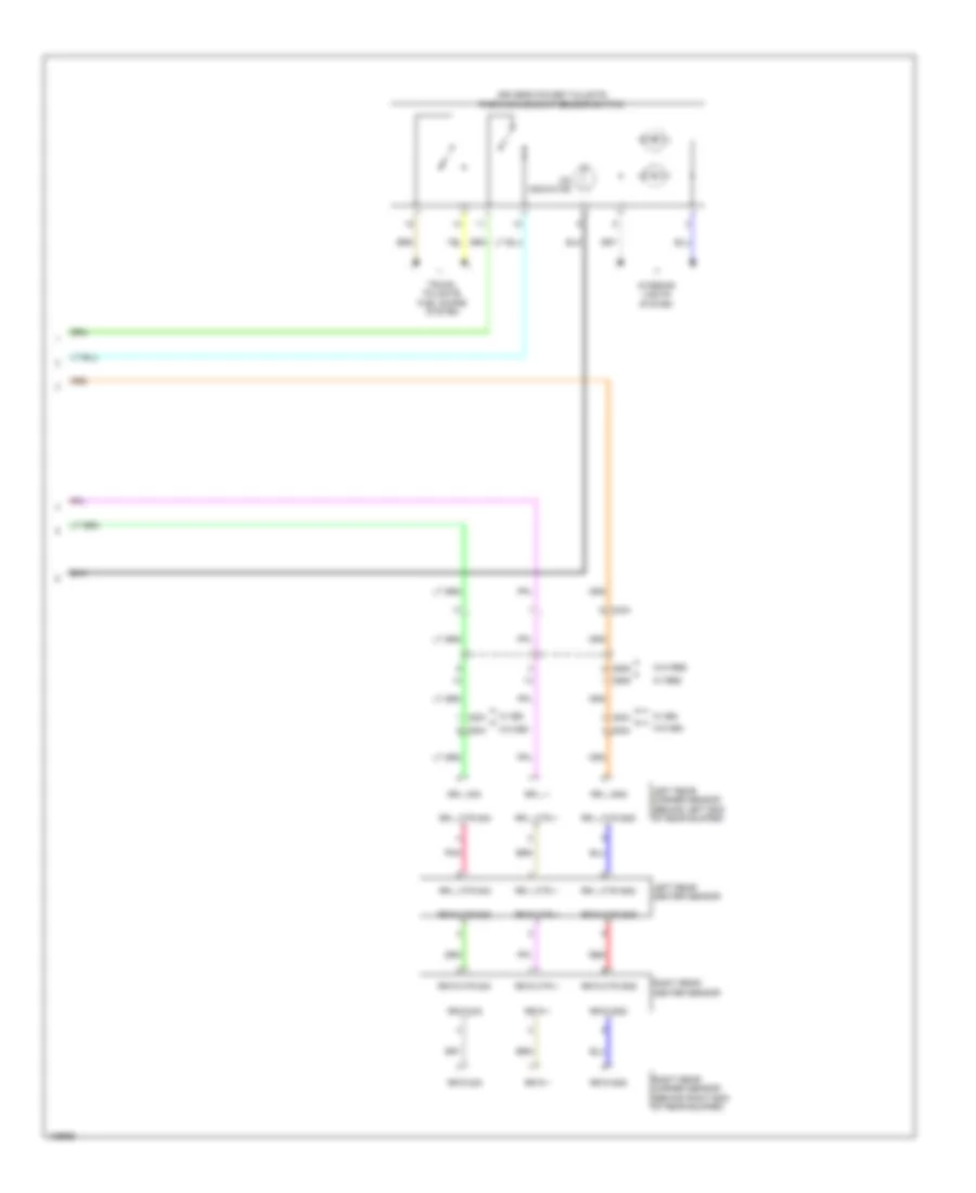
NAVIGATION
Blind Spot Information System Wiring Diagram for Honda Odyssey EX-L 2014
 https://portal-diagnostov.com/license.html
Automotive Electricians Portal FZCO
Automotive Electricians Portal FZCO
https://portal-diagnostov.com/license.html
https://portal-diagnostov.com/license.html
Automotive Electricians Portal FZCO
Automotive Electricians Portal FZCO
List of elements for Blind Spot Information System Wiring Diagram for Honda Odyssey EX-L 2014:
- As bsi ind+
- B-can h
- B-can l
- Bsi ind
- C401
- C404
- C414
- C609
- C804
- Computer data lines system
- Control circuits
- Dr bsi ind+
- Driver's j/b 1 (behind instrument cluster)
- Driver's under-dash fuse/relay box (left end of dash)
- Fuse 7.5a
- G401 (upper left end of dash)
- G402 (left side of dash)
- G405 (right end of dash)
- G801 (behind rear of left rear side trim panel)
- Gauge control module
- Gnd
- Hot in on or start
- Ig1 ecu rr
- J/c c472 (front passenger's door)
- Left bsi alert indicator
- Left bsi radar unit (behind left end of rear bumper)
- Multi-information display (mid)
- Pnk
- Power distribution system
- Rear fuse box (behind left rear side trim panel)
- Red
- Right bsi alert indicator
- Right bsi radar unit (behind right end of rear bumper)
- Transceiver b-can
- W/ memory
- W/o memory
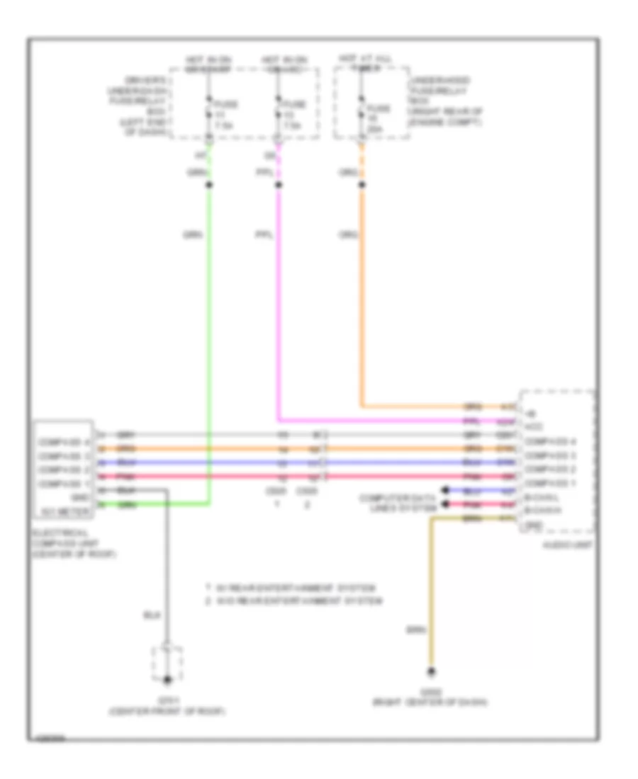
Compass Wiring Diagram for Honda Odyssey EX-L 2014
List of elements for Compass Wiring Diagram for Honda Odyssey EX-L 2014:
- A24
- Acc
- Audio unit
- B-can h
- B-can l
- C10
- C19
- C20
- C505
- Compass 1
- Compass 2
- Compass 3
- Compass 4
- Computer data lines system
- Driver's under-dash fuse/relay box (left end of dash)
- Electrical compass unit (center of roof)
- Fuse 20a
- Fuse 7.5a
- G502 (right center of dash)
- G701 (center front of roof)
- Gnd
- Hot at all times
- Hot in on or acc
- Hot in on or start
- Ig1 meter
- Pnk
- Under-hood fuse/relay box (right rear of engine compt)
- W/ rear entertainment system
- W/o rear entertainment system
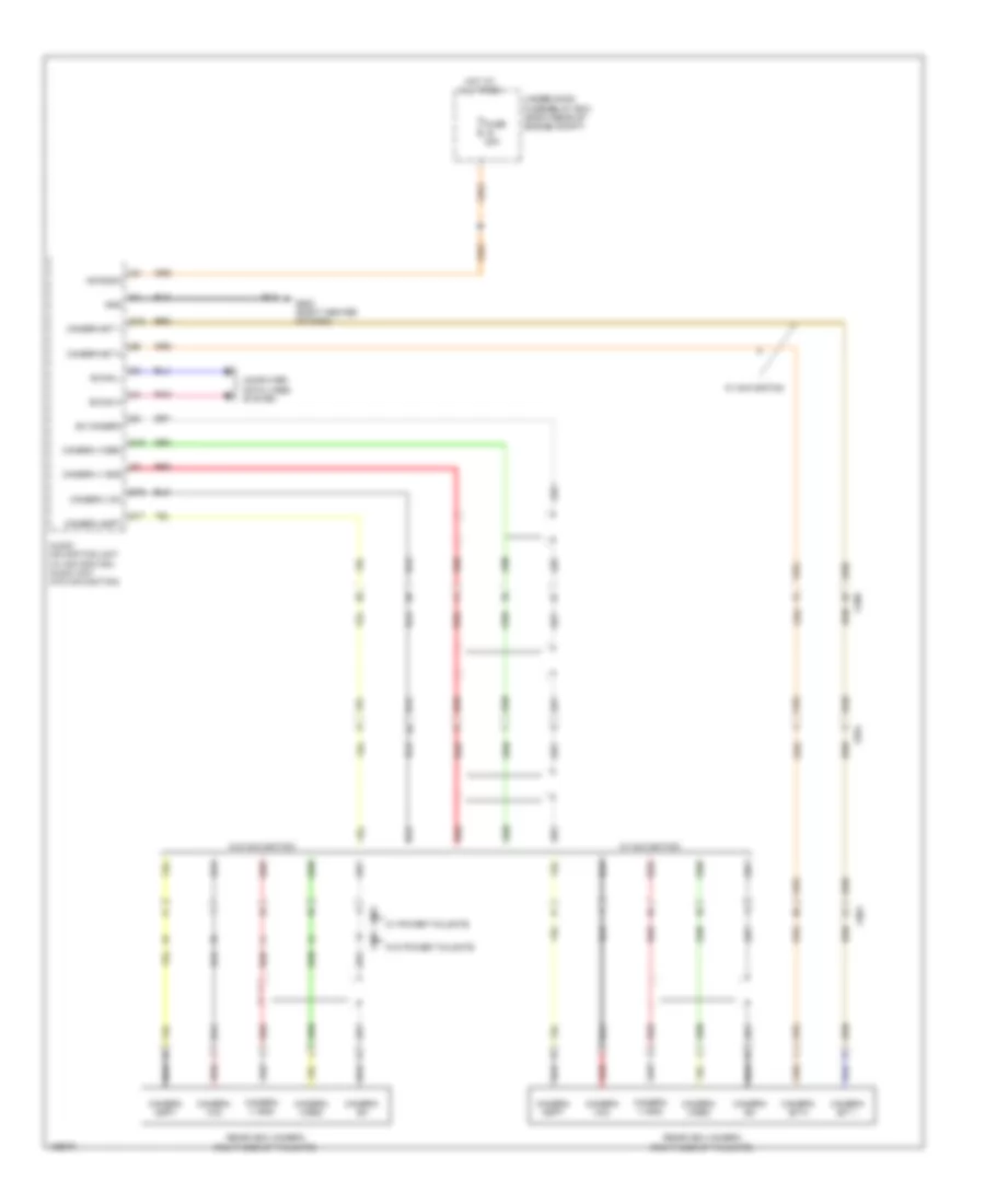
Hands Free Module Wiring Diagram, with Touch Screen (1 of 2) for Honda Odyssey EX-L 2014
List of elements for Hands Free Module Wiring Diagram, with Touch Screen (1 of 2) for Honda Odyssey EX-L 2014:
- +b radio
- A10
- A11
- A12
- A13
- A14
- A15
- A16
- A17
- A18
- A19
- A20
- A21
- A22
- A23
- A24
- A25
- A26
- A27
- A28
- A29
- A30
- A31
- A32
- Audio unit (w/o navigation) audio-navigation unit (w/ navigation)
- B-can h
- B-can l
- C12
- C412
- C413
- C505
- Computer data lines system
- D10
- D12
- F13
- F14
- Fuse 20a
- G502 (right center of dash)
- Ga +b
- Ga audio l+
- Ga audio l-
- Ga audio r+
- Ga audio r-
- Ga bus+
- Ga bus-
- Ga gnd
- Ga sys on
- Gnd
- Handsfreelink control unit (right center of dash)
- Hft mute
- Hft strg sw
- Hft-navi mic sh
- Hft-navi mic+
- Hft-navi mic-
- Hot at all times
- Junction connector c502 (right center of dash)
- Mic pwr
- Mic sh
- Mic+
- Mic-
- Nca
- On ga sys
- Pnk
- Rear controller & screen (w/ res)
- Red
- Remote gnd
- Remote sw
- Sh ga audio
- Telem sig +
- Telem sig sh
- Telem sig+
- Telem sig-
- Under-hood fuse/relay box (right rear of engine compt)
- Usb data+
- Usb data-
- Usb gnd
- Usb sh
- Usb vbus
- W/ navigation
- W/ res
Hands Free Module Wiring Diagram, with Touch Screen (2 of 2) for Honda Odyssey EX-L 2014
List of elements for Hands Free Module Wiring Diagram, with Touch Screen (2 of 2) for Honda Odyssey EX-L 2014:
- (behind front of right rear side trim panel) tuner unit
- (right center of dash) active noise cancellation unit
- (w/ navigation) front hfl-navigation-anc microphone (w/o navigation) front hfl-anc microphone
- (w/o navigation: front roof console)
- A10
- A11
- A12
- A13
- A18
- Audio remote switch
- C13
- C18
- C505
- C506
- Cable reel (in steering column)
- Display button
- Dvd player unit (w/ res)
- Fr mic in+
- Fr mic in-
- G402 (left side of dash)
- Ga +b
- Ga audio l+
- Ga audio l-
- Ga audio r+
- Ga audio r-
- Ga gnd
- Ga sys on
- Hfl switch (w/o navigation) hfl navigation voice control switch (w/ navigation)
- Hft mute
- Interior lights system
- Junction connector c501 (right center of dash)
- Mic pwr
- Mic+
- Mic-
- Off hook button
- On hook/ back button
- Pnk
- Red
- Steering wheel
- Talk button
- W/ navigation
- W/ res
- W/o navigation
- W/o res
- Xm receiver (if equipped) (base of right "d" pillar)
Hands Free Module Wiring Diagram, without Touch Screen for Honda Odyssey EX-L 2014
List of elements for Hands Free Module Wiring Diagram, without Touch Screen for Honda Odyssey EX-L 2014:
- (front roof console) front hfl-anc microphone
- (right end of dash) active noise cancellation unit
- +b radio
- A11
- A13
- A18
- A23
- Audio remote switch
- Audio unit
- B-can h
- B-can l
- B12
- C13
- C18
- C412
- C413
- C505
- C506
- Cable reel (in steering column)
- Computer data lines system
- D10
- D12
- Display button
- Fr mic in+
- Fr mic in-
- Fuse 20a
- G402 (left side of dash)
- G502 (right center of dash)
- Ga +b
- Ga audio l+
- Ga audio l-
- Ga audio r+
- Ga audio r-
- Ga audio sh
- Ga bus +
- Ga bus -
- Ga gnd
- Ga sys on
- Gnd
- Handsfreelink control unit (right center of dash)
- Hfl mute
- Hfl strg sw
- Hfl switch
- Hft mute
- Hot at all times
- Interior lights system
- Junction connector c501 (right center of dash)
- Junction connector c502 (right center of dash)
- Mic +
- Mic -
- Mic pwr
- Mic sh
- Mic+
- Mic-
- Off hook button
- On hook/ back button
- Pnk
- Red
- Remote gnd
- Remote sw
- Steering wheel
- Talk button
- Telem sig +
- Telem sig -
- Telem sig sh
- Under-hood fuse/relay box (right rear of engine compt)
- Xm receiver (if equipped) (base of right "d" pillar)
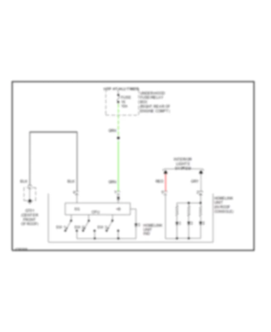
Home Link Remote Control Wiring Diagram for Honda Odyssey EX-L 2014
List of elements for Home Link Remote Control Wiring Diagram for Honda Odyssey EX-L 2014:
- Cpu
- Fuse 10a
- G701 (center front of roof)
- Homelink unit (in roof console)
- Homelink unit ind
- Hot at all times
- Interior lights system
- Red
- Sw 1
- Sw 2
- Sw 3
- Under-hood fuse/relay box (right rear of engine compt)
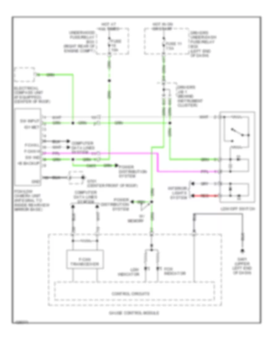
Lane Departure Warning Wiring Diagram for Honda Odyssey EX-L 2014
List of elements for Lane Departure Warning Wiring Diagram for Honda Odyssey EX-L 2014:
- +b backup
- C405
- Computer data lines system
- Control circuits
- Driver's j/b 1 (behind instrument cluster)
- Driver's under-dash fuse/relay box (left end of dash)
- Electrical compass unit (if equipped) (center of roof)
- F-can h
- F-can l
- F-can transceiver
- Fcw indicator
- Fcw/ldw camera unit (integral to inside rearview mirror base)
- Fuse 10a
- Fuse 11 7.5a
- G401 (upper left end of dash)
- G701 (center front of roof)
- Gauge control module
- Gnd
- Hot at all times
- Hot in on or start
- Ig1 met
- Interior lights system
- Ldw indicator
- Ldw/off switch
- Power distribution system
- Red
- Sw ind
- Sw input
- Under-hood fuse/relay box (right rear of engine compt)
- W/ memory
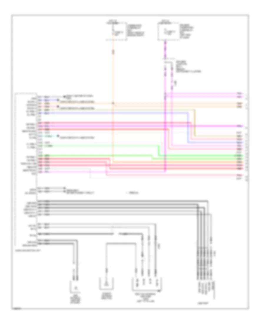
Lane Watch Camera Wiring Diagram for Honda Odyssey EX-L 2014
List of elements for Lane Watch Camera Wiring Diagram for Honda Odyssey EX-L 2014:
- +b radio
- Audio unit (w/o navigation) audio navigation unit (w/ navigation)
- B-can h
- B-can l
- Bsm cam +b
- Bsm cam sh
- Bsm cam v gnd
- Bsm camm vid
- Bsm comm1
- Bsm comm2
- Bsn sw
- C412
- C417
- Combination light switch
- Computer data lines system
- Fuse 20a
- G20
- G21
- G22
- G23
- G402 (left side of dash)
- G502 (right center of dash)
- Gnd
- Hot at all times
- Lane watch camera
- Lane watch camera switch
- Lwc comm1
- Lwc comm2
- Lwc sh
- Lwc vcc
- Lwc vid
- Nca
- Pnk
- Red
- Right power mirror
- Under-hood fuse/relay box (right rear of engine compt)
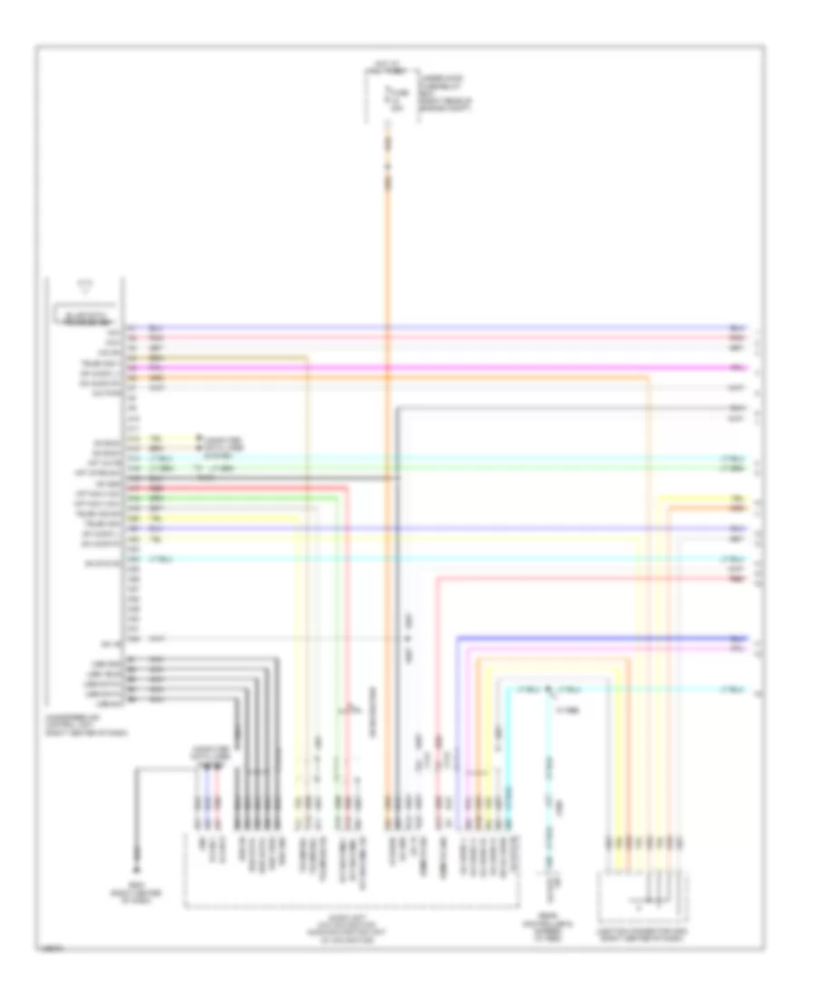
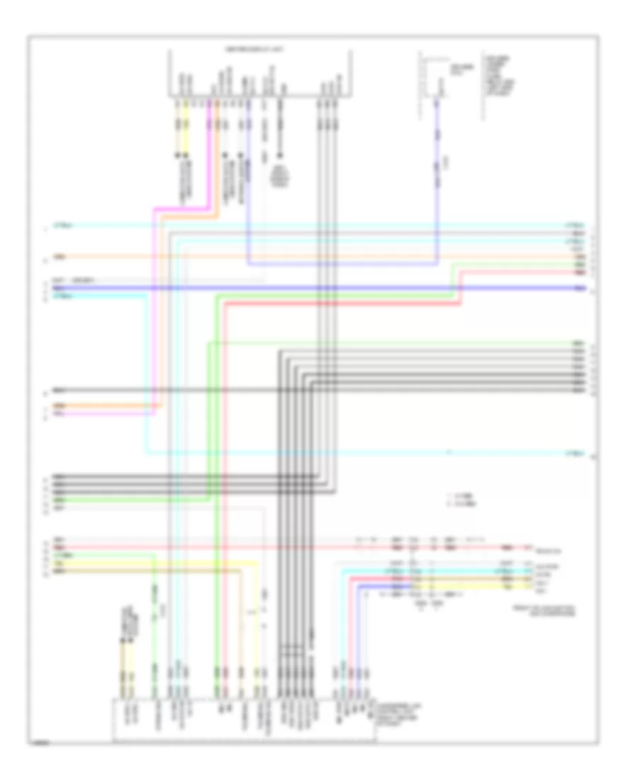
Navigation Wiring Diagram (1 of 7) for Honda Odyssey EX-L 2014
List of elements for Navigation Wiring Diagram (1 of 7) for Honda Odyssey EX-L 2014:
- (right center of dash) g502
- +b radio
- A10
- A11
- A12
- A13
- A14
- A15
- A16
- A17
- A18
- A19
- A20
- A21
- A22
- A23
- A24
- Acc
- Ant b+
- Audio navigation unit
- B-can h
- B-can l
- C405
- C418
- C570
- Computer data lines system
- Driver's junction box 1 (behind instrument cluster)
- Driver's under-dash fuse/relay box (left end of dash)
- Fl pre +
- Fl pre -
- Fr pre +
- Fr pre -
- Fuse 13 7.5a
- Fuse 15 20a
- Gnd
- Gps antenna (center of dash)
- Gps sig
- Gps sig gnd
- Hot at all times
- Hot in acc or on
- K-line
- Nca
- Pnk
- Premium
- Radio sw (+b)
- Rds tmc antenna amplifier (usa) (left "c" pillar)
- Rear seat entertainment circuit
- Red
- Remote
- Remote gnd
- Remote sw
- Rf in
- Rf sh
- Rl pre +
- Rl pre -
- Rr pre +
- Rr pre -
- Scty2
- Sh (spdif)
- Spdif
- Tmc sig
- Under-hood fuse/relay box (right rear of engine compt)
- Usb data +
- Usb data -
- Usb gnd
- Usb port
- Usb sh
- Usb vbus
- Window antenna (rds tmc)
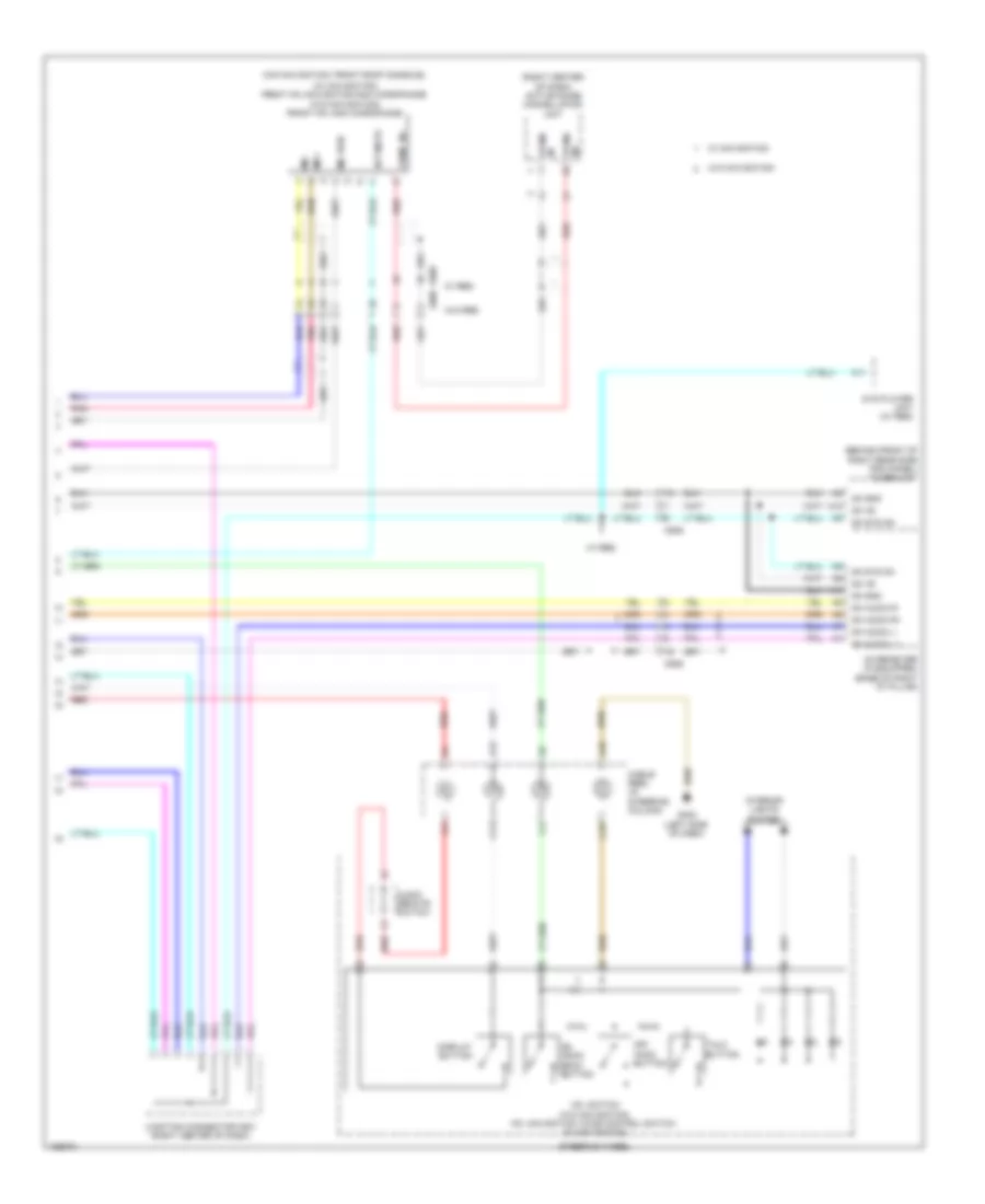
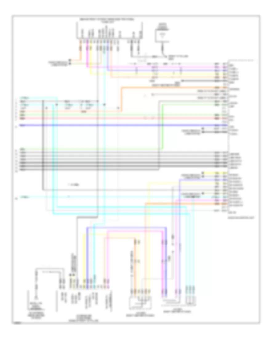
Navigation Wiring Diagram (2 of 7) for Honda Odyssey EX-L 2014
List of elements for Navigation Wiring Diagram (2 of 7) for Honda Odyssey EX-L 2014:
- (right center of dash) j/c c504
- A13
- A18
- Acc
- Audio remote switch
- Base
- Base w/ memory & premium
- Base w/o memory
- C13
- C18
- C412
- C413
- C414
- Cable reel (in steering column)
- Center switch panel
- Channel down switch
- Channel up switch
- Display button
- Front passenger's door speaker
- G402 (left side of dash)
- G501 (right side of dash)
- Gnd
- Hfl-navigation voice control switch
- Illumi+
- Illumi-
- Interior lights system
- Jog
- Jog sh
- Mode switch
- Off hook button
- On hook/ back button
- Pnk
- Premium
- Red
- Right tweeter
- Steering wheel
- Talk button
- Volume down switch
- Volume up switch
- W/ memory
- W/o memory
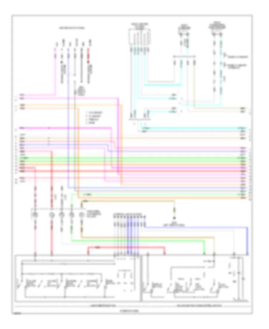
Navigation Wiring Diagram (3 of 7) for Honda Odyssey EX-L 2014
List of elements for Navigation Wiring Diagram (3 of 7) for Honda Odyssey EX-L 2014:
- (j/c c409: upper left end of dash) (w/o memory) j/c c408 (w/ memory) j/c c409
- (premium) left satellite speaker
- (premium) right satellite speaker
- Audio navigation unit
- Aux det
- Aux gnd
- Aux lch
- Aux rch
- Aux sh gnd
- Aux sig gnd
- Auxiliary jack assembly
- Base
- C10
- C11
- C12
- C13
- C14
- C15
- C16
- C17
- C18
- C401
- C410
- C412
- C413
- C507
- C604
- C605
- C652
- C654
- C681
- C691
- Driver's door speaker
- Left cess articulated harness
- Left rear door speaker
- Left tweeter
- N10
- Pnk
- Premium
- Red
- Rg gnd
- Rg l+
- Rg sh
- Right cess articulated harness
- Right rear door speaker
- Rs 485+
- Rs 485-
- Sh rs485
- Subwoofer
- Telem sig sh
- Telem sig+
- Telem sig-
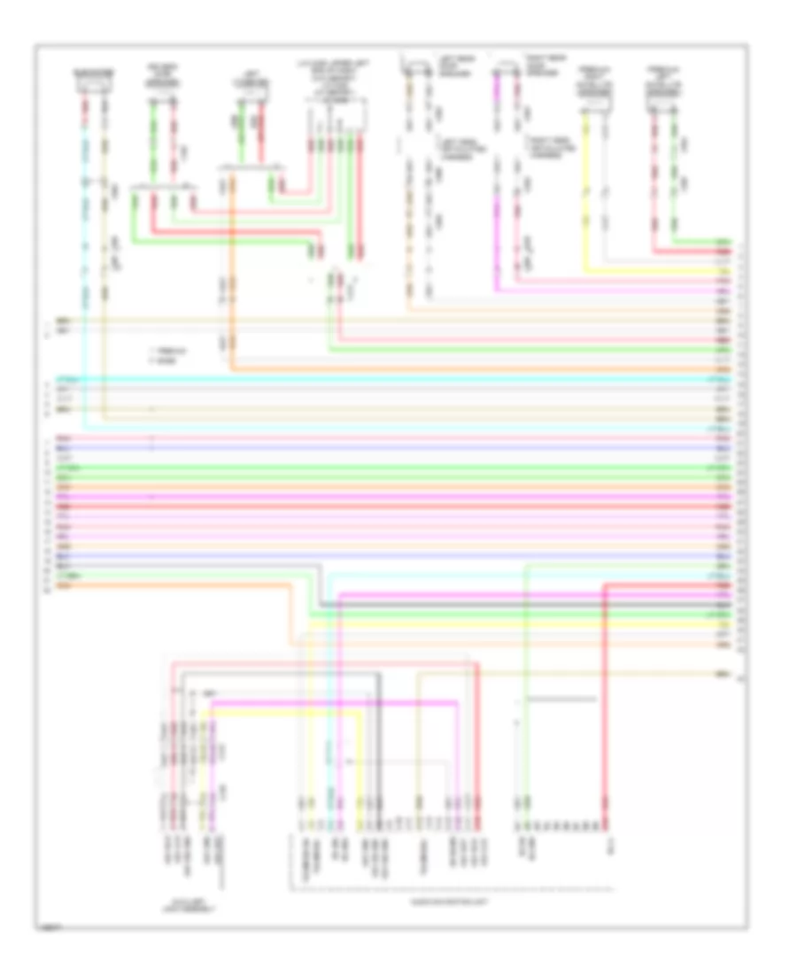
Navigation Wiring Diagram (4 of 7) for Honda Odyssey EX-L 2014
List of elements for Navigation Wiring Diagram (4 of 7) for Honda Odyssey EX-L 2014:
- (right end of dash) stereo amplifier
- +b audio amp
- A10
- A11
- A12
- A13
- A14
- A15
- A16
- A17
- A18
- A19
- A20
- A21
- A22
- A23
- A24
- Anc chk2
- Anc f +
- Anc f -
- Anc r +
- Anc r -
- Audio l
- Audio r
- Audio-navigation unit
- B10
- B11
- B12
- B13
- B14
- B15
- B16
- B17
- B18
- B19
- B20
- B21
- B22
- B23
- B24
- B25
- B26
- B27
- B28
- Back lt
- Bsm cam +b
- Bsm cam gnd
- Bsm cam sh
- Bsm cam vid
- Bsm comm1
- Bsm comm2
- Bsm sw
- Camera adpt
- Camera bit 0
- Camera bit 1
- Camera v gnd
- Camera vcc
- Camera video
- Ctr pre +
- Ctr pre -
- Ctr sp+
- Ctr sp-
- Exterior lights system
- Fl pre +
- Fl pre -
- Fl sp +
- Fl sp -
- Fl tw sp +
- Fl tw sp -
- Fr pre +
- Fr pre -
- Fr sp+
- Fr sp-
- Fr tw sp +
- Fr tw sp -
- Fuse 1 30a
- G10
- G11
- G12
- G13
- G14
- G15
- G16
- G17
- G18
- G19
- G20
- G21
- G22
- G23
- G24
- G501 (right side of dash)
- Gnd
- Gvif sh
- Gvif+
- Gvif-
- Hot at all times
- Hp l
- Hp r
- L10 rr aux det
- L11
- L12
- L13
- L14
- L15
- L16
- L17
- L18
- L19
- L20
- L21
- L22
- L23
- L3 res vid sh
- L4 hp r/l sh
- L5 hp r/l gnd
- L8 audio gnd
- L9 audio sh
- Lh roof sp +
- Lh roof sp -
- Navigation system
- Nca
- Passenger's under-dash fuse/relay box (behind right kick panel)
- Pnk
- Premium
- Radio sw
- Rear seat entertainment circuit
- Red
- Res vid gnd
- Res vid sig
- Rg gnd
- Rg l+
- Rh roof sp +
- Rh roof sp -
- Rl pre +
- Rl pre -
- Rl sp +
- Rl sp -
- Rl sr sp +
- Rl sr sp -
- Rr ntsc
- Rr ntsc gnd
- Rr pre +
- Rr pre -
- Rr sp +
- Rr sp -
- Rr sr sp +
- Rr sr sp -
- Rs 485+
- Rs 485-
- Sh camera
- Subw pre +
- Subw pre -
- Subw sp+
- Subw sp-
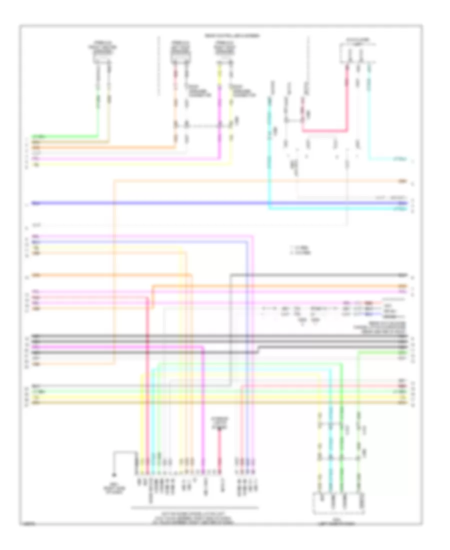
Navigation Wiring Diagram (5 of 7) for Honda Odyssey EX-L 2014
List of elements for Navigation Wiring Diagram (5 of 7) for Honda Odyssey EX-L 2014:
- (premium) front center speaker
- (premium) left roof speaker
- (premium) right roof speaker
- A10
- A11
- A13
- A22
- Acc
- Active noise cancellation unit (w/o touch screen: right end of dash) (w/ touch screen: right center of dash)
- Anc chk2
- Anc f +
- Anc f -
- Anc r +
- Anc r -
- C205
- C412
- C413
- C505
- Cssama
- Cssamc
- Dvd player unit
- Fr mic in+
- Fr mic in-
- G501 (right side of dash)
- Ga sys
- Gnd
- Interior lights system
- Intr lt
- Nca
- Nep
- Pcm (left side of dash)
- Pnk
- Radio sw (+b)
- Rear active noise cancellation microphone (rear center of roof)
- Rear controller & screen
- Red
- Roof speaker connector
- Rr mic +
- Rr mic -
- Rr mic in+
- Scty2
- Scty3
- Scty4
- Vssout
- W/ res
- W/o res
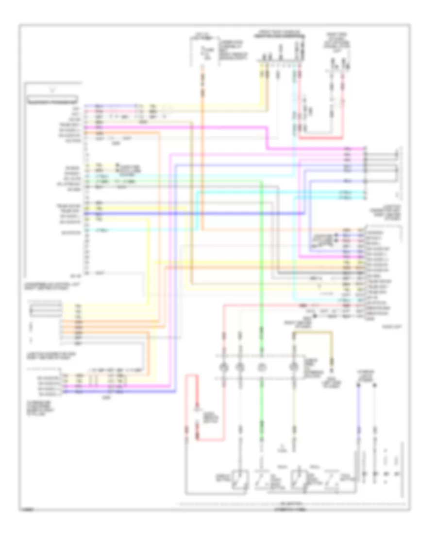
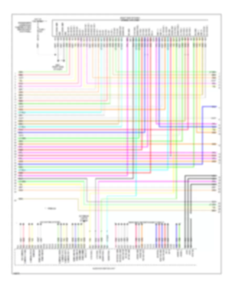
Navigation Wiring Diagram (6 of 7) for Honda Odyssey EX-L 2014
List of elements for Navigation Wiring Diagram (6 of 7) for Honda Odyssey EX-L 2014:
- (or scty4)
- +b radio
- A10
- A11
- A12
- A13
- A14
- A15
- A16
- A17
- A18
- A19
- A20
- A24
- A32
- Acc
- C413
- C505
- Center display unit
- Driver's micu
- Driver's under- dash fuse/ relay box (left end of dash)
- Fr mic in+
- Front hfl-navigation- anc microphone
- G501 (right side of dash)
- Ga +b
- Ga bus +
- Ga bus -
- Ga bus sh
- Ga bus+
- Ga bus-
- Ga gnd
- Ga sys on
- Gnd
- Gvif sh
- Gvif+
- Gvif-
- Handsfree link control unit (right center of dash)
- Illumi+
- Interior lights system
- Lines system computer data
- Mic +
- Mic -
- Mic pwr
- Mic sh
- Mic+
- Mic-
- Mute
- Nca
- Pnk
- Red
- Scty1
- Scty2
- Strwg sw
- System data lines computer
- Telem sig sh
- Telem sig+
- Telem sig-
- Usb data+
- Usb data-
- Usb gnd
- Usb sh
- Usb vbus
- W/ res
- W/o res
Navigation Wiring Diagram (7 of 7) for Honda Odyssey EX-L 2014
List of elements for Navigation Wiring Diagram (7 of 7) for Honda Odyssey EX-L 2014:
- (am/fm) window antenna
- (behind front of right rear side trim panel) tuner unit
- (pins: f4 to f5 not used)
- (pins: f7 to f8 not used)
- (right "c" pillar) g653
- +b radio
- A10
- A11
- A12
- Audio navigation unit
- C506
- Computer data
- Computer data lines system
- D10
- D11
- D12
- F can-h
- F can-l
- F10
- F11
- F12
- F13
- F14
- F15
- F16
- F17
- F18
- G502 (right center of dash)
- Ga +b
- Ga audio l+
- Ga audio l-
- Ga audio r +
- Ga audio r -
- Ga audio r+
- Ga audio r-
- Ga bus +
- Ga bus -
- Ga bus sh
- Ga bus+
- Ga bus-
- Ga gnd
- Ga sys on
- Gnd
- J/c c501 (right center of dash)
- J/c c502 (right center of dash)
- Jog
- Jog sh
- Lines system
- Mic sh
- Mic+
- Mic-
- Nca
- Red
- Rf in
- Rf sh
- Sat ter-
- Satellite signal antenna
- Sh ga audio
- Sh gnd
- Tune l+
- Tune l-
- Tune r+
- Tune r-
- Usb data+
- Usb data-
- Usb gnd
- Usb sh
- Usb vbus
- Vsp
- W/ res
- Xm antenna (rear center of roof)
- Xm receiver (if equipped) (base of right "d" pillar)
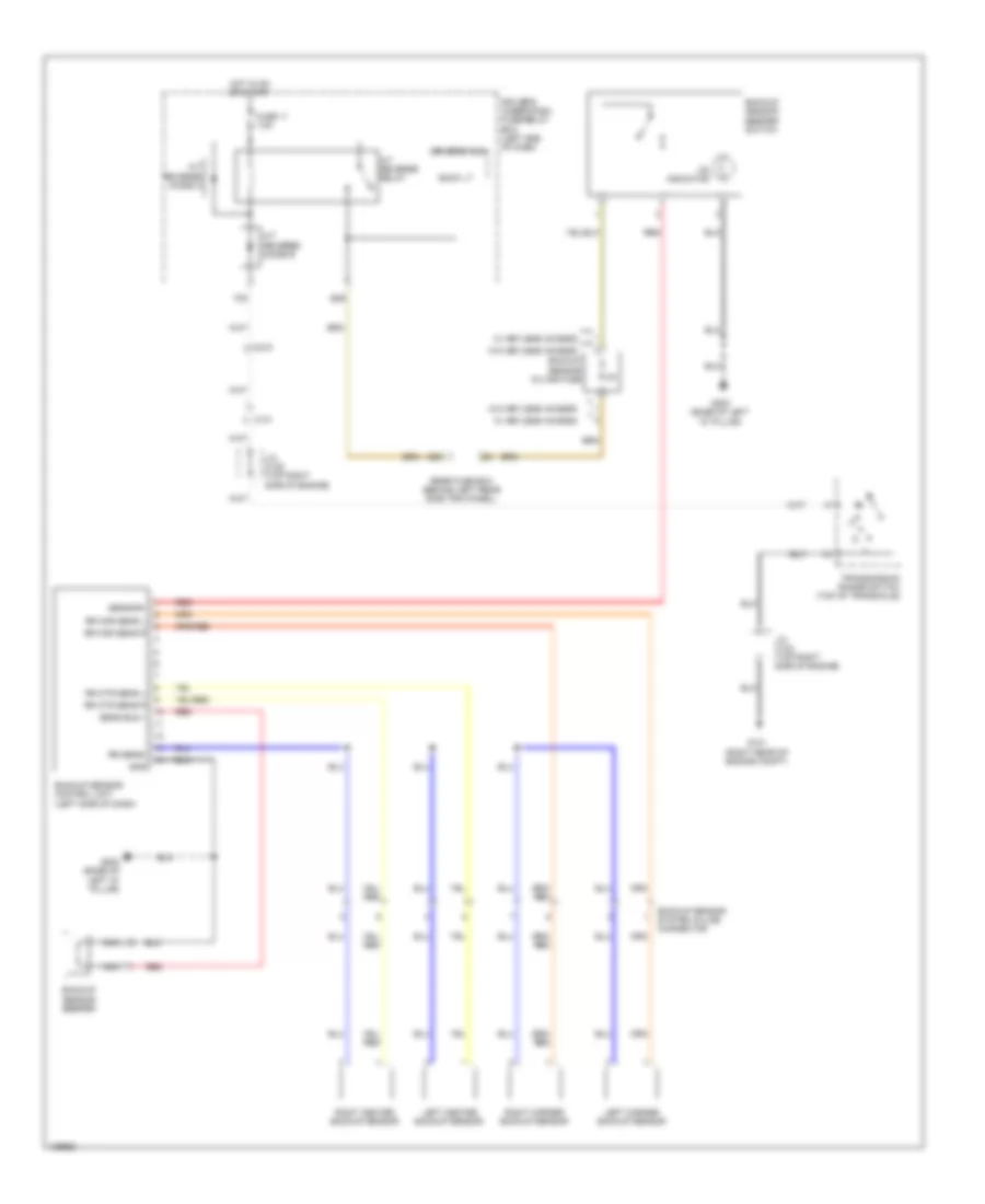
Parking Assistant Wiring Diagram, with Honda Accessory for Honda Odyssey EX-L 2014
List of elements for Parking Assistant Wiring Diagram, with Honda Accessory for Honda Odyssey EX-L 2014:
- A/t reverse diode a
- A/t reverse diode b
- A/t reverse relay
- B30
- Back lt
- Backup sensor beeper
- Backup sensor beeper switch
- Backup sensor control unit (left side of dash)
- Backup sensor in-line fuse
- Backup sensor system in-line connector
- C101
- C210
- Driver's micu
- Driver's under-dash fuse/relay box (left end of dash)
- E29
- F30
- Fuse 11 7.5a
- G101 (right rear of engine compt)
- G802 (base of left "d" pillar)
- Gnd
- Hot in on or start
- J/c c102 (top right side of engine)
- J/c c105 (top right side of engine)
- Left center backup sensor
- Left corner backup sensor
- Nca
- On indicator
- Rear fuse box (behind left rear side trim panel)
- Red
- Right center backup sensor
- Right corner backup sensor
- Rr cor sens l
- Rr cor sens r
- Rr ctr sens l
- Rr ctr sens r
- Rr sens-
- Sens buz +
- Sensor+
- Transmission range switch (top of transaxle)
- W/ keyless access
- W/o keyless access
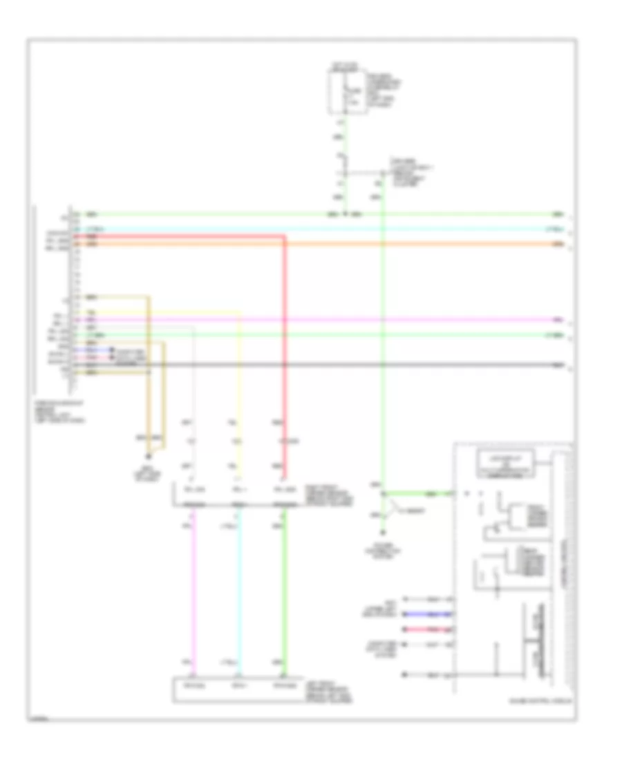
Parking Assistant Wiring Diagram, without Honda Accessory (1 of 2) for Honda Odyssey EX-L 2014
List of elements for Parking Assistant Wiring Diagram, without Honda Accessory (1 of 2) for Honda Odyssey EX-L 2014:
- B-can h
- B-can l
- C205
- Computer data lines system
- Control circuits
- Driver's junction box 1 (behind instrument cluster)
- Driver's under-dash fuse/relay box (left end of dash)
- Fr l +
- Fr l gnd
- Fr l sig
- Fr r +
- Fr r gnd
- Fr r sig
- Front corner sensor beeper
- Fuse 7.5a
- G401 (upper left end of dash)
- G402 (left side of dash)
- Gauge control module
- Gnd
- Hot in on or start
- Ig1
- Ind
- Lcd display or multi-information display (mid)
- Left front corner sensor (behind left end of front bumper)
- Main sw
- Parking & backup sensor control unit (left side of dash)
- Pnk
- Power distribution system
- Rear corner/ center sensor beeper
- Red
- Right front corner sensor (behind right end of front bumper)
- Rr l +
- Rr l gnd
- Rr l sig
- Transceiver b-can
- Transceiver f-can
- W/ memory
Parking Assistant Wiring Diagram, without Honda Accessory (2 of 2) for Honda Odyssey EX-L 2014
List of elements for Parking Assistant Wiring Diagram, without Honda Accessory (2 of 2) for Honda Odyssey EX-L 2014:
- C404
- C609
- C804
- Driver's power tailgate parking & backup sensor switch
- Interior lights system
- Left rear center sensor
- Left rear corner sensor (behind left end of rear bumper)
- On indicator
- Pnk
- Red
- Right rear center sensor
- Right rear corner sensor (behind right end of rear bumper)
- Rr l +
- Rr l ctr +
- Rr l ctr gnd
- Rr l ctr sig
- Rr l gnd
- Rr l sig
- Rr r +
- Rr r ctr +
- Rr r ctr gnd
- Rr r ctr sig
- Rr r gnd
- Rr r sig
- Trunk, tailgate, fuel doors system
- W/ bsi
- W/ res
- W/o bsi
- W/o res
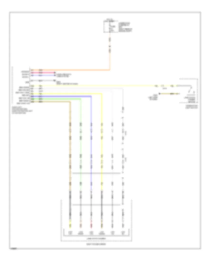
Rear Camera Wiring Diagram for Honda Odyssey EX-L 2014
List of elements for Rear Camera Wiring Diagram for Honda Odyssey EX-L 2014:
- +b radio
- Audio navigation unit (w/ navigation) audio unit (w/o navigation)
- B-can h
- B-can l
- C506
- C654
- C801
- Camera adpt
- Camera bit 0
- Camera bit 1
- Camera sh
- Camera v gnd
- Camera vcc
- Camera video
- Computer data lines system
- Fuse 20a
- G15
- G16
- G17
- G18
- G502 (right center of dash)
- Gnd
- Hot at all times
- Pnk
- Rearview camera (right side of tailgate)
- Red
- Sh camera
- Under-hood fuse/relay box (right rear of engine compt)
- W/ navigation
- W/ power tailgate
- W/o navigation
- W/o power tailgate

 Čeština
 Dansk
Dansk Deutsch
 Ελληνικά
 English
 English
 Español
 Suomi
Suomi Français
 Français
 עברית
עברית Hrvatski
 Magyar
 日本語
日本語 한국어
한국어 Nederlands
 Polski
 Português
 Português
 Română
 Русский
 Slovenčina
 Slovenščina
 Svenska
 Türkçe
 中文 (中国)