Čeština
 Dansk
Dansk Deutsch
 Ελληνικά
 English
 English
 Español
 Suomi
Suomi Français
 Français
 עברית
עברית Hrvatski
 Magyar
 日本語
日本語 한국어
한국어 Nederlands
 Polski
 Português
 Português
 Română
 Русский
 Slovenčina
 Slovenščina
 Svenska
 Türkçe
 中文 (中国)

NAVIGATION
Compass Wiring Diagram for Honda Pilot Touring 2014


List of elements for Compass Wiring Diagram for Honda Pilot Touring 2014:
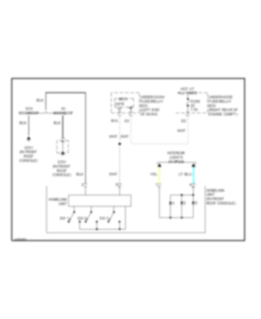
Home Link Remote Control Wiring Diagram for Honda Pilot Touring 2014
List of elements for Home Link Remote Control Wiring Diagram for Honda Pilot Touring 2014:
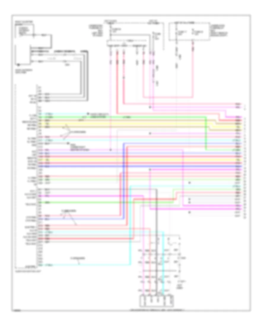
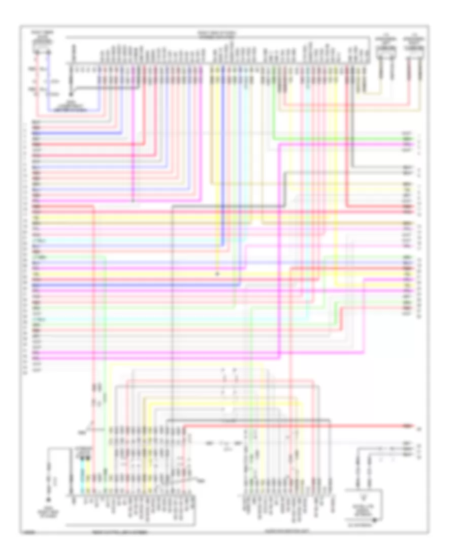
Navigation Wiring Diagram (1 of 6) for Honda Pilot Touring 2014
List of elements for Navigation Wiring Diagram (1 of 6) for Honda Pilot Touring 2014:
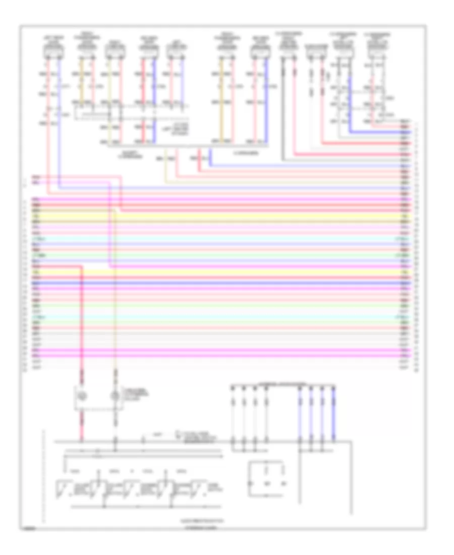
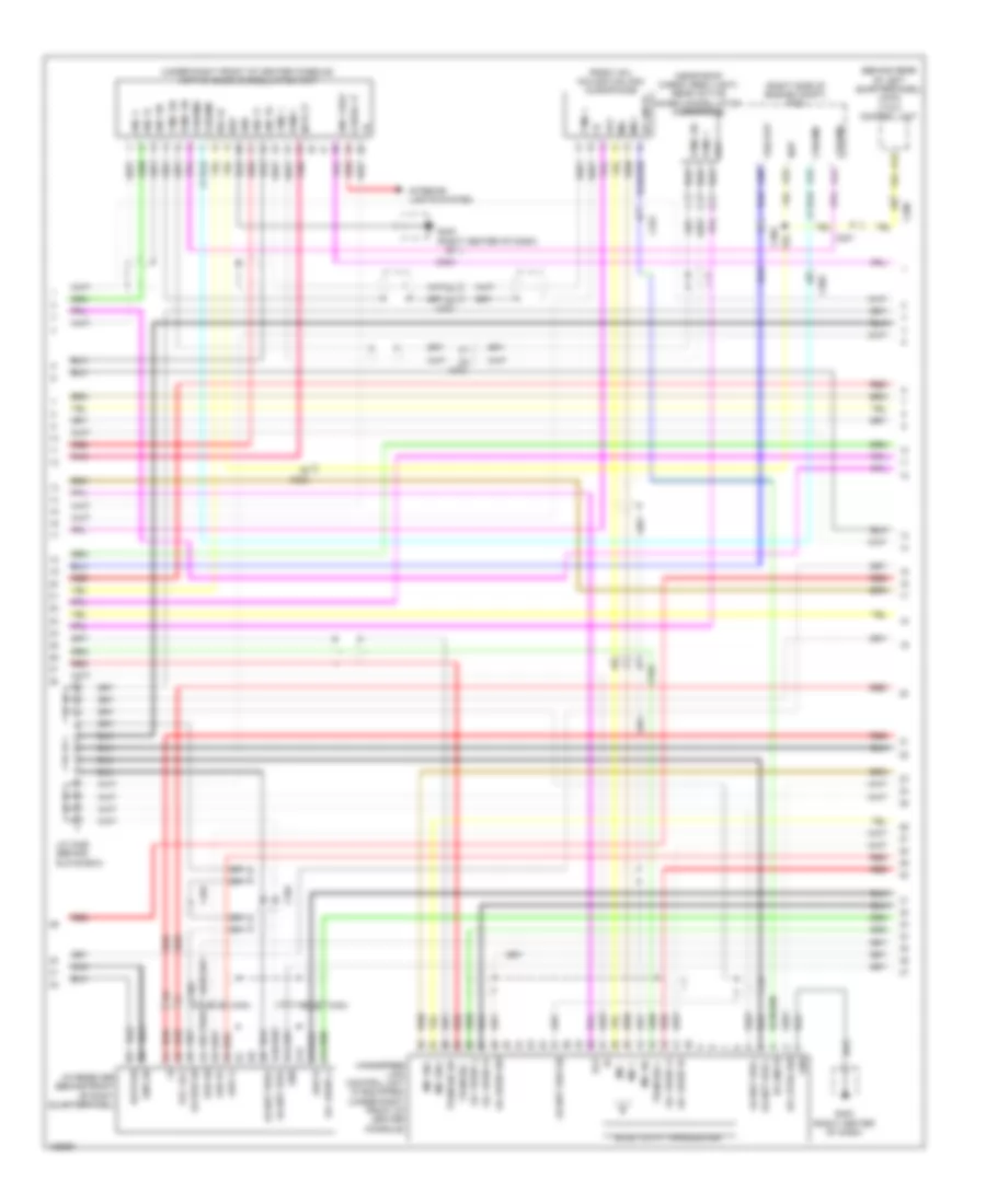
Navigation Wiring Diagram (2 of 6) for Honda Pilot Touring 2014
List of elements for Navigation Wiring Diagram (2 of 6) for Honda Pilot Touring 2014:
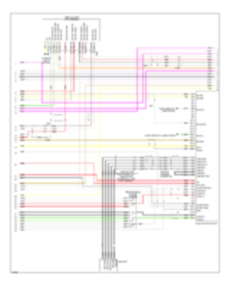
Navigation Wiring Diagram (3 of 6) for Honda Pilot Touring 2014
List of elements for Navigation Wiring Diagram (3 of 6) for Honda Pilot Touring 2014:
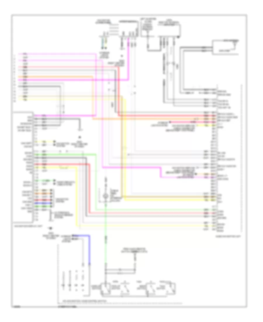
Navigation Wiring Diagram (4 of 6) for Honda Pilot Touring 2014
List of elements for Navigation Wiring Diagram (4 of 6) for Honda Pilot Touring 2014:
Navigation Wiring Diagram (5 of 6) for Honda Pilot Touring 2014
List of elements for Navigation Wiring Diagram (5 of 6) for Honda Pilot Touring 2014:
Navigation Wiring Diagram (6 of 6) for Honda Pilot Touring 2014
List of elements for Navigation Wiring Diagram (6 of 6) for Honda Pilot Touring 2014:
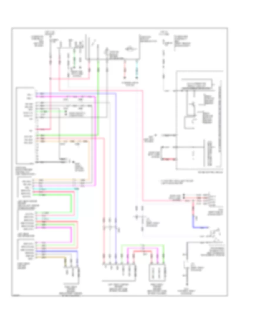
Parking Assistant Wiring Diagram, Except Honda Accessory for Honda Pilot Touring 2014
List of elements for Parking Assistant Wiring Diagram, Except Honda Accessory for Honda Pilot Touring 2014:
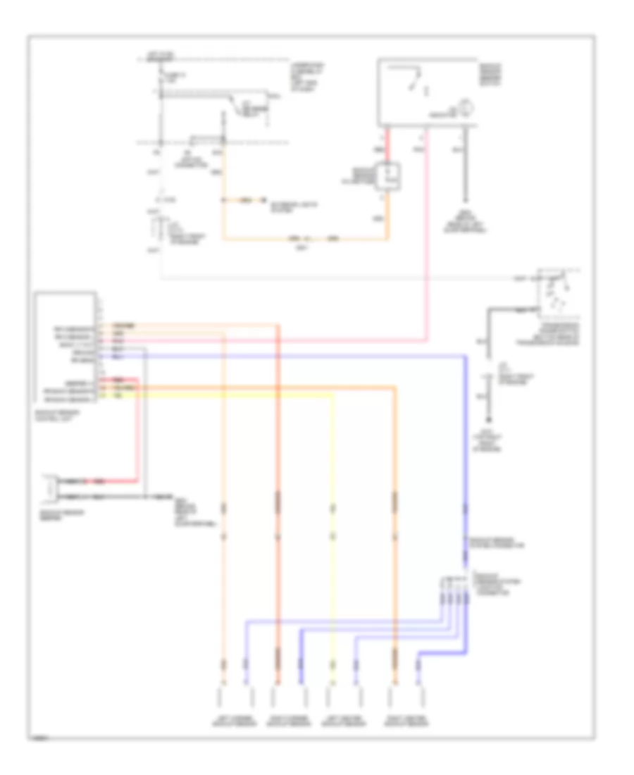
Parking Assistant Wiring Diagram, Honda Accessory for Honda Pilot Touring 2014
List of elements for Parking Assistant Wiring Diagram, Honda Accessory for Honda Pilot Touring 2014:
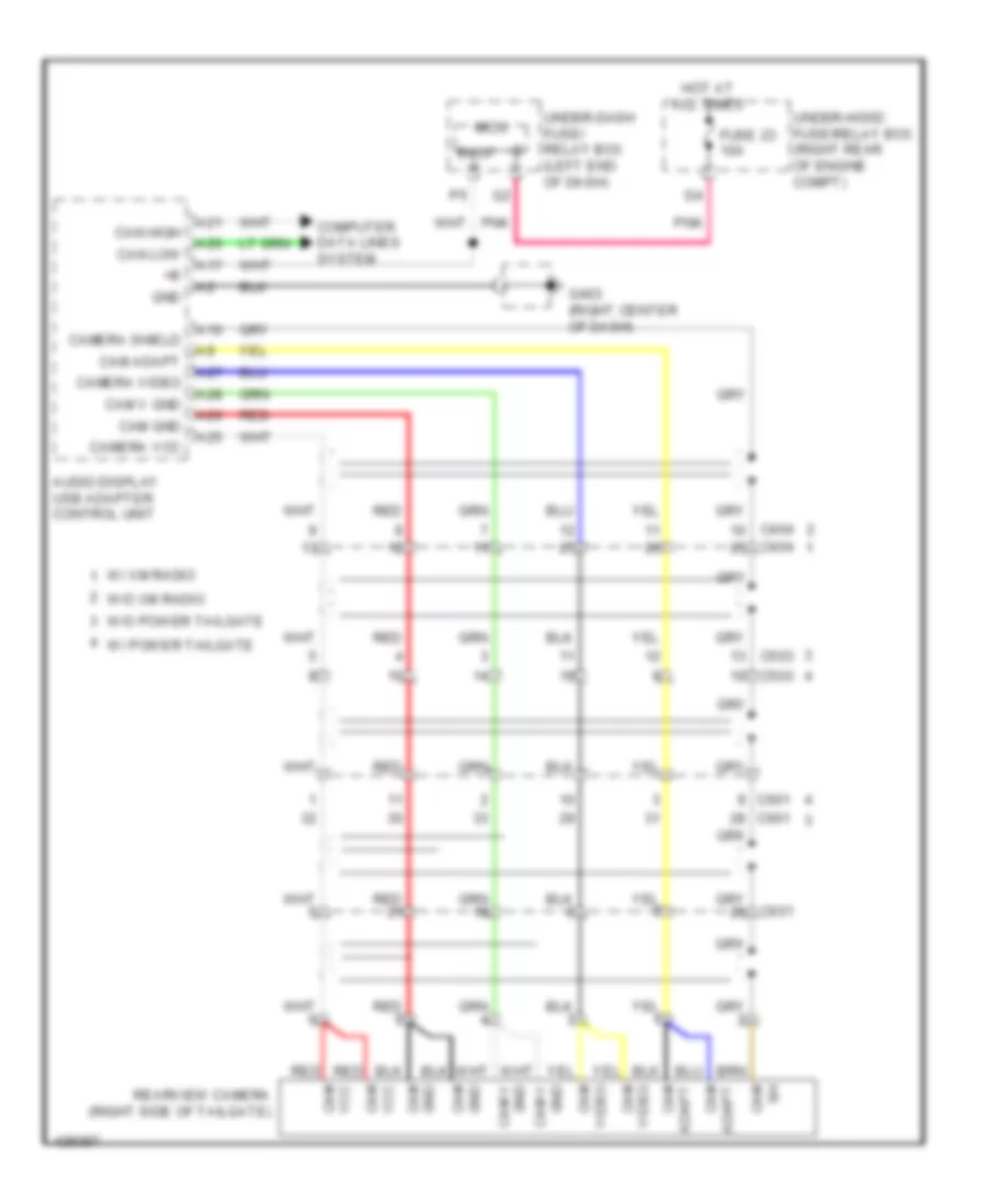
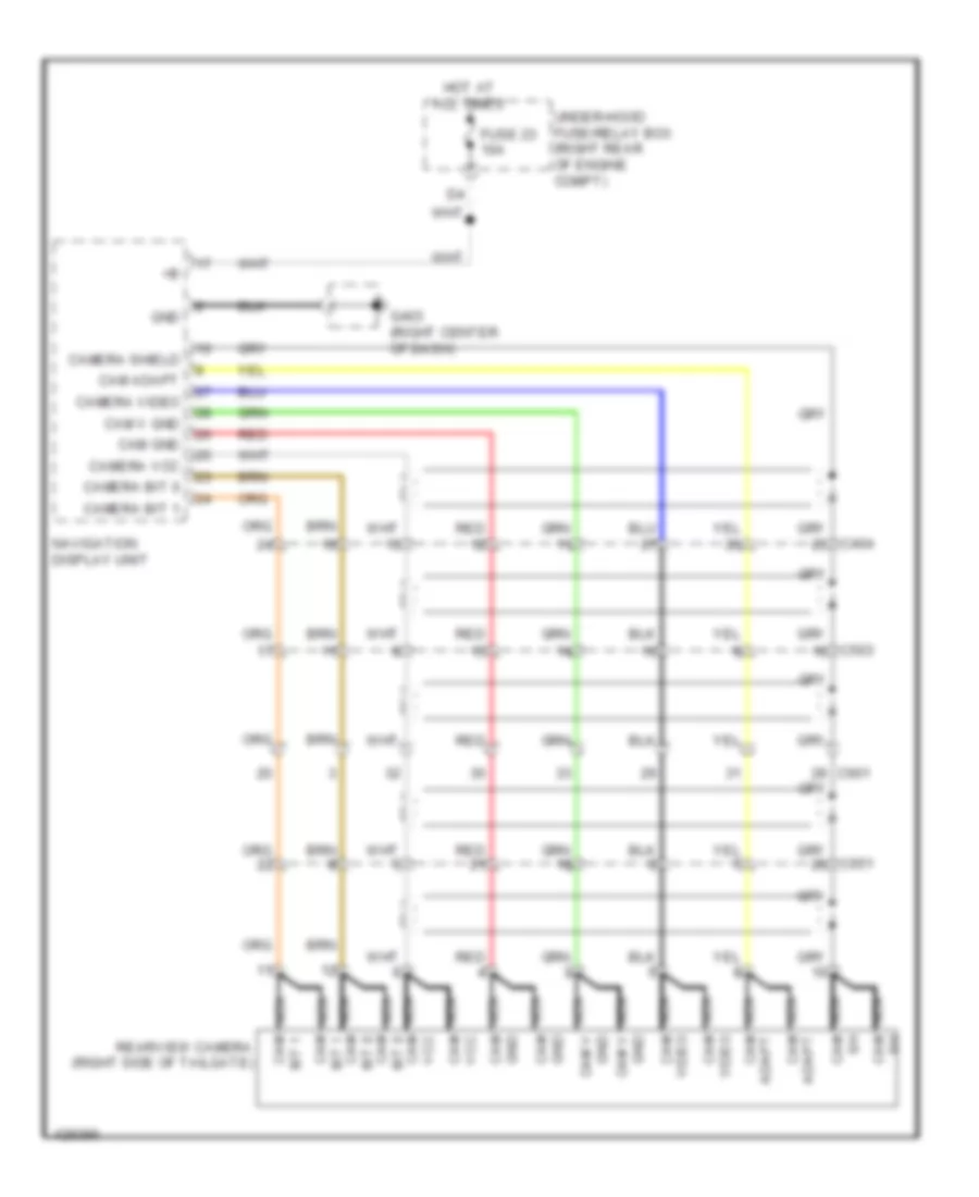
Rear Camera Wiring Diagram, with Navigation for Honda Pilot Touring 2014
List of elements for Rear Camera Wiring Diagram, with Navigation for Honda Pilot Touring 2014:
Rear Camera Wiring Diagram, without Navigation for Honda Pilot Touring 2014
List of elements for Rear Camera Wiring Diagram, without Navigation for Honda Pilot Touring 2014: