POWER DISTRIBUTION
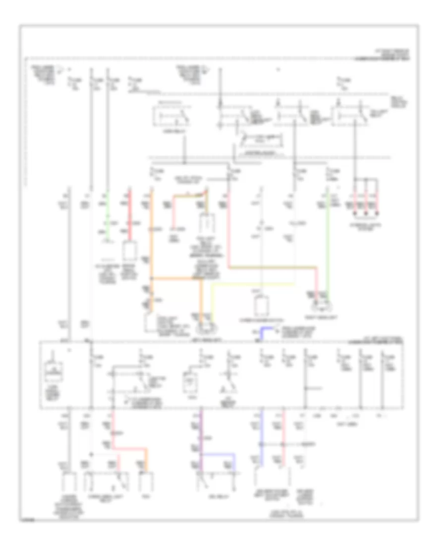
Power Distribution Wiring Diagram (1 of 5) for Honda Ridgeline RTS 2013
 https://portal-diagnostov.com/license.html
Automotive Electricians Portal FZCO
Automotive Electricians Portal FZCO
https://portal-diagnostov.com/license.html
https://portal-diagnostov.com/license.html
Automotive Electricians Portal FZCO
Automotive Electricians Portal FZCO
List of elements for Power Distribution Wiring Diagram (1 of 5) for Honda Ridgeline RTS 2013:
- (at right rear of engine compt) under-hood fuse/relay box
- (not used)
- 120a
- 40a
- A/c compressor clutch relay
- A/c condenser fan relay
- A31
- Alternator
- Auxiliary under- dash fuse holder 1 (left end of dash)
- Auxiliary under-hood relay box (left rear of engine compt)
- Battery
- C102
- C302
- C401
- C410 (trailer electric brake connector)
- Cigarette lighter (honda accessory)
- Driver's accessory power socket
- Eld unit
- Etcs control
- From fuse 32 (diagram 5 of 5)
- From under- dash fuse/ d
- From under- dash fuse/ relay box (diagram 5 of 5)
- Front accessory power socket relay (left side of dash)
- Front passenger's accessory power socket
- Fuse 15a
- Fuse 20a
- Fuse 30a
- Fuse 40a
- Fuse 7.5a
- G1 (left front of engine compt)
- G202 (right rear of engine compt)
- G401 (left kick panel)
- G402 (right end of dash)
- Moonroof close relay (usa: rtl; canada: touring)
- Moonroof open relay (usa: rtl; canada: touring)
- Multi- fuse 22
- Pcm
- Radiator fan relay
- Relay
- Relay box (diagram 4 of 5)
- Seat heater relay (usa: rtl, canada: touring)
- Starter
- Starter solenoid
- Starting/ charging system
- Sts fuse 7.5a
- T101
- T102
- T2 s
- To under- dash fuse/ relay box (diagram 2 of 5)
- To under- hood fuse/ relay box (diagram 2 of 5)
- To under- hood fuse/ relay box (diagram 3 of 5)
- To under-hood fuse/relay box fuse 16 (diagram 2 of 5)
- Tpms control unit
- Trailer lighting control unit
- Trailer lighting relay 1
- Trailer lighting relay 2
- Transmission
- Vsa modulator control unit
- Vtm-4 relay
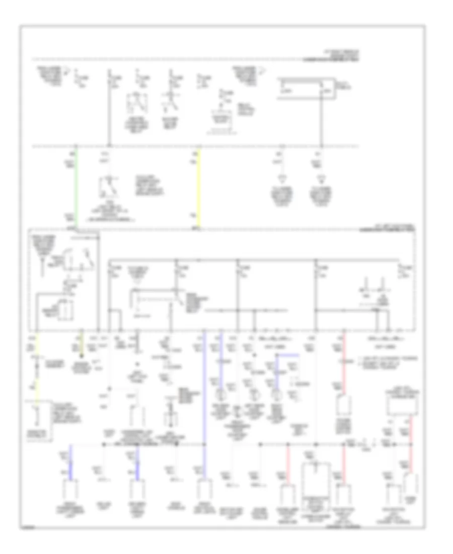
Power Distribution Wiring Diagram (2 of 5) for Honda Ridgeline RTS 2013
List of elements for Power Distribution Wiring Diagram (2 of 5) for Honda Ridgeline RTS 2013:
- (at left kick panel) under-dash fuse/relay box
- (at right rear of engine compt) under-hood fuse/relay box
- (not
- (not used)
- (usa: rts, rtl & canada: touring)
- +b hazard
- A/f sensor relay
- Ac inverter unit (usa: rtl; canada: touring)
- Auxiliary under-hood relay box (left rear of engine compt)
- Brake pedal position switch
- C201
- C203
- C204
- C205
- C206
- C302
- C503
- Cargo area light relay
- Control block
- D14
- D17
- Day lt
- Driver's lumbar support switch
- Driver's power seat adjustment switch
- Drl relay
- F11
- F13
- Fog light relay (usa: sport, rtl & canada: vp, sport, touring)
- Fog light switch (usa: sport, rtl & canada: vp, sport, touring)
- From under- hood fuse/ c
- From under- hood fuse/ g
- From under-hood fuse/relay box (diagram 1 of 5)
- Fuse (not used)
- Fuse 10a
- Fuse 15a
- Fuse 20a
- Fuse 40a
- Fuse 7.5a
- H14
- H15
- H16
- H17
- H18
- Hazard warning switch/front passenger's air bag cut-off indicator
- High beam headlight relay
- Horn relay
- Ignition coil relay
- Interior lights system
- Left headlight
- Low beam headlight relay
- Micu
- N40
- N45
- Pcm
- Red
- Relay box (diagram 1 of 5)
- Relay control module
- Right headlight
- Taillight relay
- To under-dash fuse/relay box (diagram 3 of 5)
- Turn signal/ hazard relay
- Usa: rt, rts & canada: dx
- Used)
- Wiper/washer switch
- X12
- X23
- X26
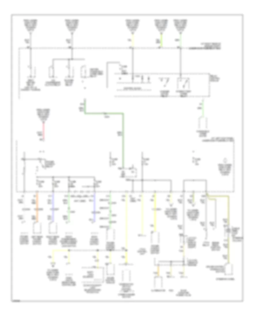
Power Distribution Wiring Diagram (3 of 5) for Honda Ridgeline RTS 2013
List of elements for Power Distribution Wiring Diagram (3 of 5) for Honda Ridgeline RTS 2013:
- (at left kick panel) under-dash fuse/relay box
- (at right rear of engine compt) under-hood fuse/relay box
- (not used)
- (usa: rtl, canada: touring) xm receiver
- +b door lock
- 20a
- 50a
- 60a
- A/c diode assembly
- A/f sensor relay
- A19
- A24
- Audio unit
- Auxiliary under-hood relay box (left rear of engine compt)
- Blower motor relay
- C402
- C453
- C454
- C505
- C506
- C507
- Canada: touring
- Ceiling light
- Combination switch control unit
- Console box light 1
- Control block
- D10
- D12
- D16
- Dlc
- Driver's door courtesy light
- Driver's vanity mirror light
- Engine controls system
- Except usa: rtl &
- F13
- Fog light relay (usa: sport, rtl & canada: vp, sport & touring)
- From under- dash fuse/ relay box (diagram 2 of 5)
- From under- hood fuse/ e
- From under- hood fuse/ f
- Front individual map lights
- Front passenger's door courtesy light
- Front passenger's vanity mirror light
- Fuse
- Fuse 10a
- Fuse 15a
- Fuse 20a
- Fuse 40a
- Fuse 7.5a
- G401 (left kick panel)
- G501 (under center console)
- Gauge control module
- Handsfree link control unit (navigation: usa: rtl, canada: touring)
- Heated windshield
- Ignition key switch/key light
- Immobilizer control unit- receiver
- Imoes unit
- Left rear door courtesy light
- Micu
- Multi- fuse 23
- N10
- N11
- N15
- N42
- Navigation display unit (usa: rtl, canada: touring)
- Navigation unit (usa: rtl, canada: touring)
- Pgm-fi main relay 1
- Power window master switch
- Radiator fan relay
- Rear accessory power socket
- Rear accessory power socket relay
- Relay box (diagram 1 of 5)
- Relay control module
- Right rear door courtesy light
- Roof console
- To fuse 32 (diagram 5 of 5)
- To under- dash fuse/ relay box (diagram 4 of 5)
- To under- dash fuse/ relay box (diagram 5 of 5)
- Usa: rtl & canada: touring
- Vbu
- Wiper area relay
- Wiper/washer switch
- X22
- X35
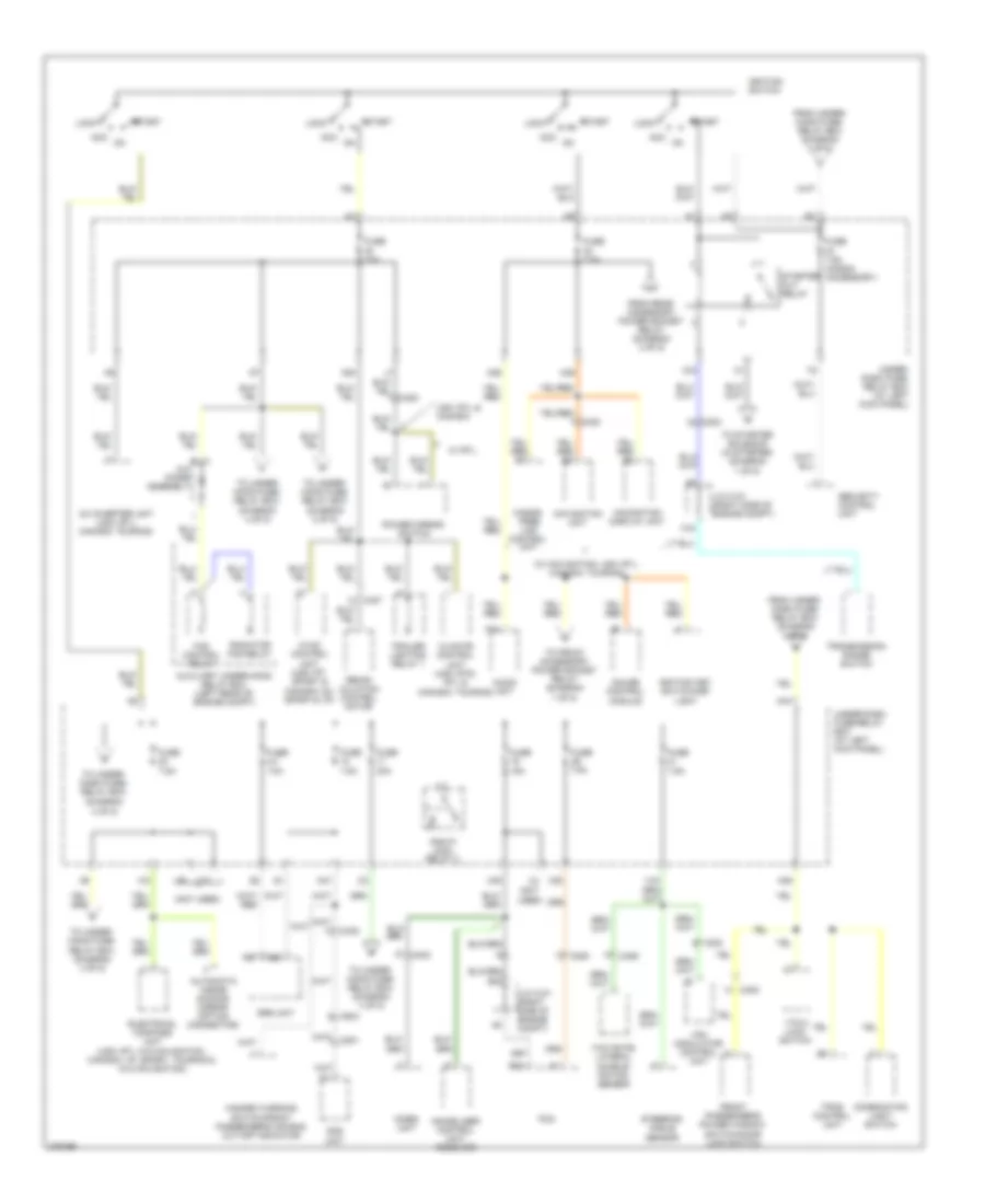
Power Distribution Wiring Diagram (4 of 5) for Honda Ridgeline RTS 2013
List of elements for Power Distribution Wiring Diagram (4 of 5) for Honda Ridgeline RTS 2013:
- (at left kick panel) under-dash fuse/relay box
- (at right rear of engine compt) under-hood fuse/relay box
- (not used)
- A/c compressor clutch relay
- A20
- Alternator
- B13
- B20
- Back power window switch
- Blower motor relay
- Brake pedal position switch
- C13
- C204
- C403
- C408
- C454
- C502
- C506
- C507
- Cable reel (top of steering column)
- Combination switch control unit
- Control block
- Cruise control combination switch
- D3 switch/shift lock solenoid/park pin switch
- Dash lights brightness controller
- E16
- Evap canister purge valve
- Fr def sw
- From under- dash fuse/ relay box (diagram 4 of 5)
- From under- dash fuse/ relay box (diagram 5 of 5)
- From under- hood fuse/ relay box (diagram 3 of 5)
- Front passenger's power window switch/door lock switch
- Fuse (not used)
- Fuse 15a
- Fuse 20a
- Fuse 7.5a
- Gauge control module
- H11
- Heated windshield wiper area relay
- Ig1
- Intermittent wiper relay
- J/c c101 (right side of engine compt)
- J/c c105 (rear of engine)
- Left rear power window switch
- Micu
- N12
- N29
- P23
- Pcm
- Power window master switch
- Power window relay
- Relay control module
- Right rear power window switch
- Seat heater relay (usa: rtl & canada: touring)
- Shift lock solenoid
- Steering wheel
- Tan
- To under- dash fuse/ relay box (diagram 5 of 5)
- To under- hood fuse/ relay box (diagram 1 of 5)
- To under- hood fuse/ relay box (diagram 4 of 5)
- Vtm-4 control unit
- Vtm-4 relay
- Washer motor relay
- Windshield wiper motor
- Wiper/washer switch
- X14
- X24
- X34
- X37
- X39
Power Distribution Wiring Diagram (5 of 5) for Honda Ridgeline RTS 2013
List of elements for Power Distribution Wiring Diagram (5 of 5) for Honda Ridgeline RTS 2013:
- (diagram 4 of 5)
- (not
- (not used)
- (w/ navigation, usa: rtl, canada: touring)
- A/c diode assembly
- A14
- A18
- A26
- A27
- Ac inverter unit (usa: rtl; canada: touring)
- Acc
- Audio unit
- Automatic inside dimming mirror (option connector)
- Auxiliary under-hood relay box (left rear of engine compt)
- B42
- C204
- C205
- C302
- C402
- C406
- C408
- C504
- Climate control unit (usa: rts, rtl & canada: touring)
- Combination light switch
- Electrical compass unit (usa: rtl w/o navigation, canada: vp, sport, touring & w/o navigation)
- Fan control relay
- From rear accessory power socket relay (diagram 3 of 5)
- From under- dash fuse/ relay box (diagram 4 of 5)
- From under- hood fuse/ relay box (diagram 3 of 5)
- Front passenger's power window switch/door lock switch
- Fuse 10a
- Fuse 15a
- Fuse 30a
- Fuse 7.5a
- Fuse 7.5a (honda accessory)
- Gauge control module
- Hands- free link control unit
- Hazard warning switch/front passenger's air bag cut-off indicator
- Hvac control unit (usa: rt, sport & canada: dx, sport & vp)
- Ignition key switch/key light
- Ignition switch
- Immobilizer control unit- receiver
- Imoes unit
- J/c c101 (right side of engine compt)
- Lock
- N20
- N36
- N38
- N39
- N41
- N44
- Navigation display unit
- Navigation unit
- Ods unit
- Pcm
- Pgm-f1 main relay 2
- Power mirror switch
- Radiator fan relay
- Recir- culation control motor
- Security control unit
- Srs unit
- Start
- Starter cut relay
- Steering angle sensor
- To front accessory power socket relay (diagram 1 of 5)
- To starter solenoid (in starter) (diagram 1 of 5)
- To under- dash fuse/ relay box
- To under- hood fuse/ relay box (diagram 4 of 5)
- Tpms control unit
- Trailer lighting relay 1
- Transmission range switch
- Under- dash fuse/ relay box (at left kick panel)
- Under-dash fuse/relay box (at left kick panel)
- Usa: rtl & canada
- Used)
- Vsa modulator control unit
- Vtm-4 lock switch
- W/ rtl
- X16
- X17
- X20
- X33
- X38
- Yaw rate- lateral accele- ration sensor

 Čeština
 Dansk
Dansk Deutsch
 Ελληνικά
 English
 English
 Español
 Suomi
Suomi Français
 Français
 עברית
עברית Hrvatski
 Magyar
 日本語
日本語 한국어
한국어 Nederlands
 Polski
 Português
 Português
 Română
 Русский
 Slovenčina
 Slovenščina
 Svenska
 Türkçe
 中文 (中国)