AIR CONDITIONING
Heater Wiring Diagram, with Stripped Chassis for Ford Econoline E250 2001
 https://portal-diagnostov.com/license.html
Automotive Electricians Portal FZCO
Automotive Electricians Portal FZCO
https://portal-diagnostov.com/license.html
https://portal-diagnostov.com/license.html
Automotive Electricians Portal FZCO
Automotive Electricians Portal FZCO
List of elements for Heater Wiring Diagram, with Stripped Chassis for Ford Econoline E250 2001:
- (engine control harness, near breakout to 42 pin in-line connector, left rear of engine compartment below access cover) s195
- (left rear of engine compartment, near master cylinder) g116
- Battery junction box (in left front of engine compartment)
- Blower motor
- Blower motor relay
- Fuse 50a
- Fused blower motor feed
- Hot at all times
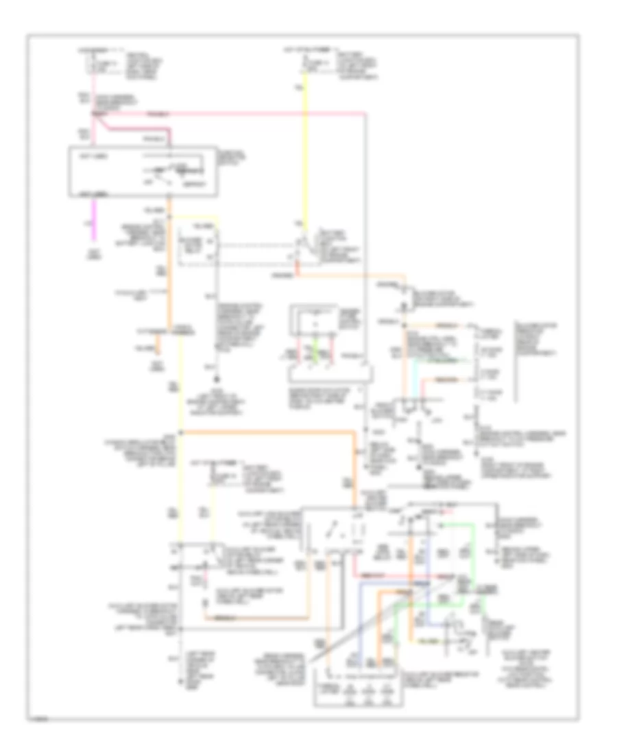
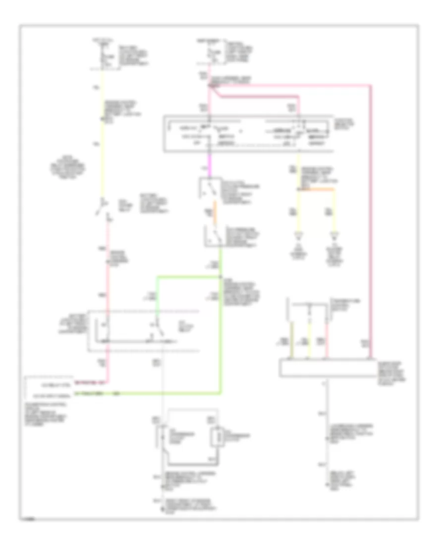
Heater Wiring Diagram, without Stripped Chassis for Ford Econoline E250 2001
List of elements for Heater Wiring Diagram, without Stripped Chassis for Ford Econoline E250 2001:
- (auxiliary blower motor harness, in breakout to 12-pin in-line connector left rear cargo area) s401
- (behind upper left side of dash, near kick panel) g202
- (below left side of dash, near kick panel) g202
- (engine control harness, near breakout to 76 pin in-line connector, left rear of engine compartment, on firewall) s122
- (left rear corner of vehicle, near left rear door) g999
- (main harness near breakout to radio) s202
- (not used)
- (rear harness, near breakout to 12 pin gray in-line connector, along left "b" pillar near roof)
- .25 ohms +/- 10%
- .8 ohms +/- 10%
- 2.7 ohms +/- 10%
- 87a
- Auxiliary blower motor (above left rear wheelwell)
- Auxiliary blower motor relay (in left rear corner of vehicle, above wheelwell)
- Auxiliary blower resistor (above left rear wheelwell)
- Auxiliary heater blower switch note: (w/o rear contrl: low position) (with rear control: rear control)
- Auxiliary heater blower switch off
- Auxiliary high blower motor relay (in left rear corner of vehicle, above wheelwell)
- Battery junction box (in left front of engine compartment)
- Blend door actuator (behind right side of dash, on a/c-heater plenum)
- Blower motor (on right side of engine compartment)
- Blower motor relay
- Blower motor resistor (in right rear of engine compartment)
- Central junction box left side of dash, near kick panel)
- Cutaways
- Cutout switch)
- Def/flr
- Defrost
- Floor
- Front blower switch
- Function selector switch
- Fuse 13 15a
- Fuse 13 50a
- Fuse 16 50a
- G108 (left front of engine compartment, at left upper radiator support)
- G109 (right front of engine compartment, at right upper radiator support)
- G202 (behind upper left side of dash, near kick panel)
- High
- Hot at all times
- Hot in run
- Low
- Off
- Pnk/ (main harness, near breakout to radio) s203
- Rear auxiliary blower switch
- S111 (engine control harness, near breakout to battery junction box)
- S143 (engine control harness, near breakout to a/c pressure cut-out switch)
- S202 (main harness, near breakout to radio)
- S303
- S304
- S305
- S323
- S400 (window regulator relay switch harness, near breakout for 2 pin connector behind left "b" pillar)
- See note below
- Temper- ature control switch
- Thermal limiter
- Vans & wagons
- Vent
- W/ rear control
- W/auxiliary heat
- W/o rear con- trol
4.2L
4.2L, Manual A/C Wiring Diagram, with Stripped Chassis for Ford Econoline E250 2001
List of elements for 4.2L, Manual A/C Wiring Diagram, with Stripped Chassis for Ford Econoline E250 2001:
- (engine control harness, near breakout to battery junction box) s110
- (fuel charge harness, near breakout to fuel injector 6) s107
- (left rear of engine compartment, near master cylinder) g116
- (not used)
- (right rear of engine compartment) g105
- 87a
- A/c clutch relay
- A/c compressor clutch
- A/c compressor clutch diode
- A/c demand
- A/c on input signal
- A/c relay control
- A/c switch
- Battery junction box (in left front of engine compartment)
- Blower motor
- Blower motor relay
- C1001f
- Central junction box (left side of dash, near kick panel)
- Fuse 10a
- Fuse 15a
- Fuse 30a
- Fuse 50a
- Fused blower motor feed
- Hot at all times
- Hot in run
- Note: pcm power relay energized w/ignition switch in run or start position
- Pcm power relay
- Powertrain control module (in left rear of engine compartment, near brake master cylinder)
- Red
- S142 (engine control harness, near breakout to 8 pin in-line connector, center of engine compartment, near mass air flow sensor)
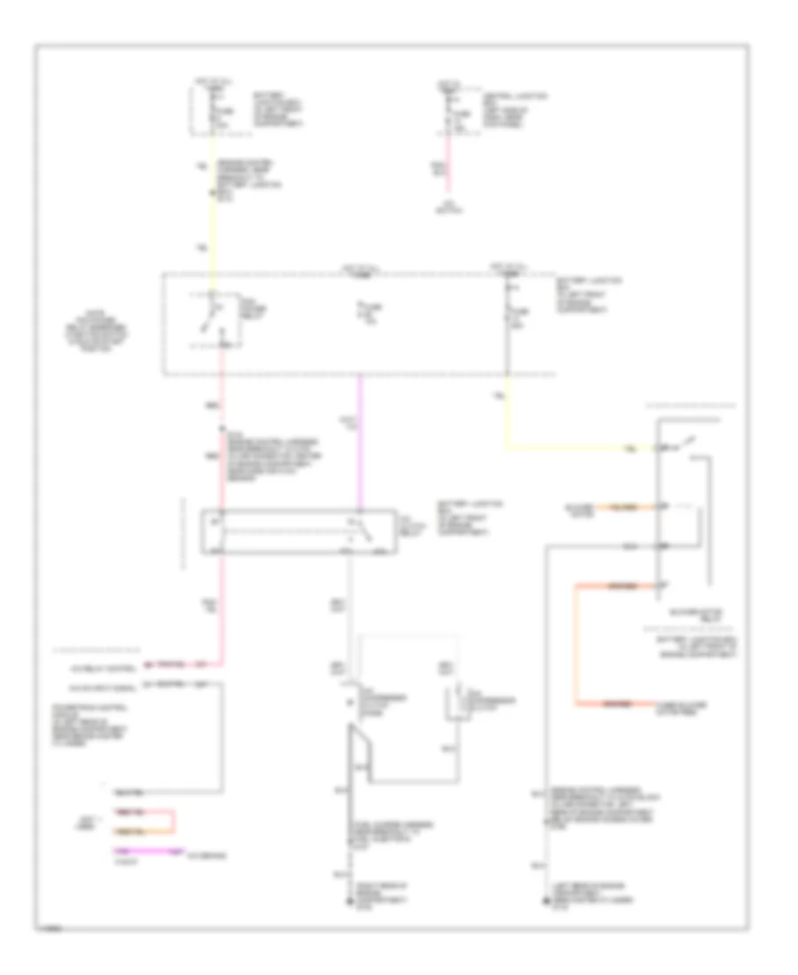
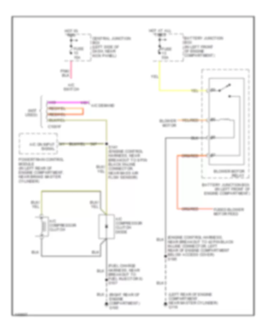
4.2L, Manual A/C Wiring Diagram, without Stripped Chassis for Ford Econoline E250 2001
List of elements for 4.2L, Manual A/C Wiring Diagram, without Stripped Chassis for Ford Econoline E250 2001:
- (below left side of dash, near left kick panel) g202
- (engine control harness) s142
- (engine control harness, near breakout to battery junction box) s110
- (fuel charge harness, near breakout to fuel injector 6) s107
- (lower dash harness, near breakout to brake pedal position (bpp) switch) s223
- (right front of engine compartment, at right upper radiator support) g109
- 87a
- A/c clutch cycling pressure switch (in right front of engine compartment)
- A/c clutch relay
- A/c compressor clutch
- A/c compressor clutch diode
- A/c on input signal
- A/c pressure cut-out switch (in right front of engine compartment)
- A/c relay control
- Battery junction box (in left front of engine compartment)
- Blend door actuator (behind right side of dash, on a/c heater plenum)
- Central junction box (left side of dash, near kick panel)
- Def/flr
- Defrost
- Floor
- Function selector switch
- Fuse 10a
- Fuse 15a
- Fuse 30a
- Hot at all times
- Hot in run
- Max a/c
- Norm a/c
- Note: pcm power relay energized w/ignition switch in run or start position
- Off
- Pcm power relay
- Powertrain control module (in left rear of engine compartment, near brake master cylinder)
- Red
- Temperature control switch
- To blower motor relay (diagram 2 of 2)
- To s400 (diagram 2 of 2)
- Vent
- Vent norm a/c
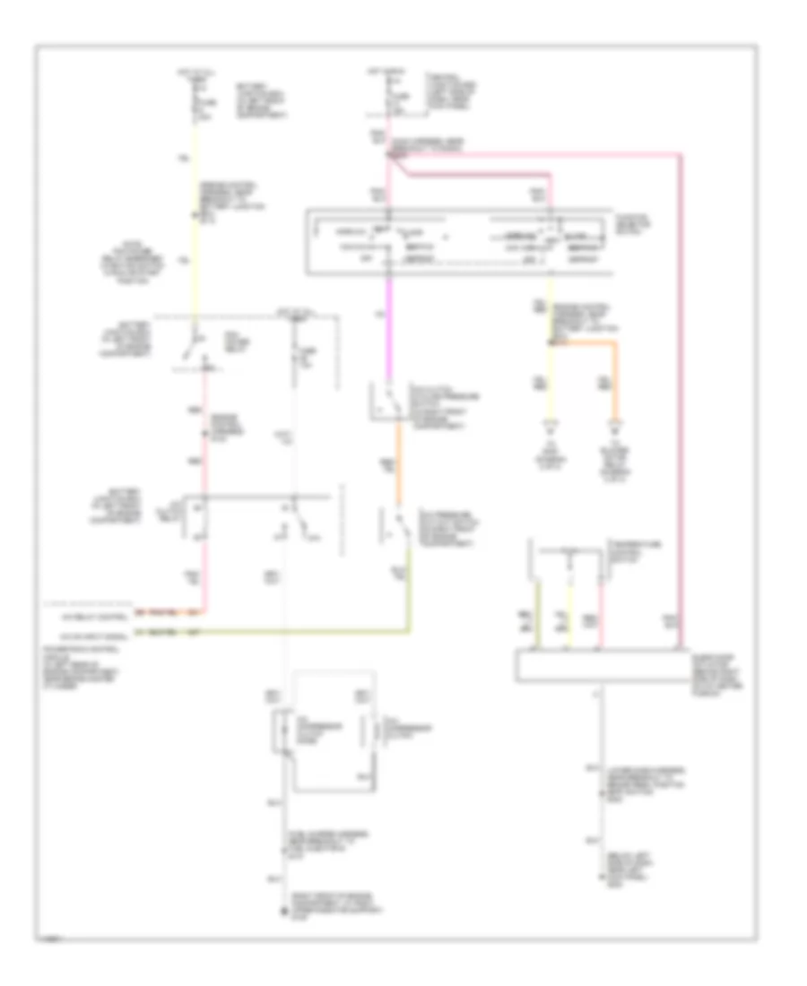
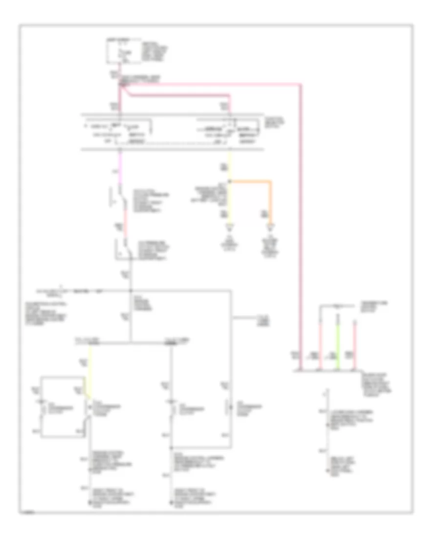
4.2L, Manual A/C Wiring Diagram, without Stripped Chassis for Ford Econoline E250 2001
List of elements for 4.2L, Manual A/C Wiring Diagram, without Stripped Chassis for Ford Econoline E250 2001:
- (behind upper left side of dash, near kick panel) g202
- (engine control harness, near breakout to 76 pin black in-line connector, left rear of engine compartment, on firewall) s122
- (in right rear of engine compartment) blower motor resistor
- (left front of engine compartment, at left upper radiator support) g108
- (left rear corner of vehicle, near left rear door) g999
- (not used)
- (rear harness, near breakout to 12 pin gray in-line connector, along left "b" pillar, near roof) s303
- (right front of engine compartment, at right upper radiator support) g109
- (window regulator relay switch harness, near breakout to 2 pin connector, behind left "b" pillar) s400
- .25 ohms +/- 10%
- .8 ohms +/- 10%
- 2.7 ohms +/- 10%
- 87a
- Auxiliary a/c-heater blower switch
- Auxiliary blower motor (above left rear wheelwell)
- Auxiliary blower motor relay (in left rear corner of vehicle, above wheelwell)
- Auxiliary blower resistor (above left rear wheelwell)
- Auxiliary high blower motor relay (in left rear corner of vehicle, above wheelwell)
- Battery junction box (in left front of engine compartment)
- Blower motor (on right side of engine compartment)
- Blower motor relay
- Cutaways
- From s111 (diagram 1 of 2)
- Front blower switch
- Fuse 50a
- High
- Hot at all times
- Low
- Low/rear
- Off
- Rear auxiliary blower switch
- S143 (engine control harness, near breakout to a/c pressure cutout switch)
- S144 (engine control harness, near breakout to a/c pressure cutout switch)
- S202 (main harness, near breakout to radio)
- S304 (rear harness, near breakout to 12 pin gray in-line connector, along left "b" pillar, near roof)
- S305 (rear harness, near breakout to 12 pin gray in-line connector, along left "b" pillar, near roof)
- S401 (auxiliary blower motor harness, in breakout to 12 pin gray in-line connector, left rear cargo area, near auxiliary blower motor)
- Thermal limiter
- Vans & wagons
- W/ auxiliary a/c
- W/ rear control
- W/o rear control
4.6L
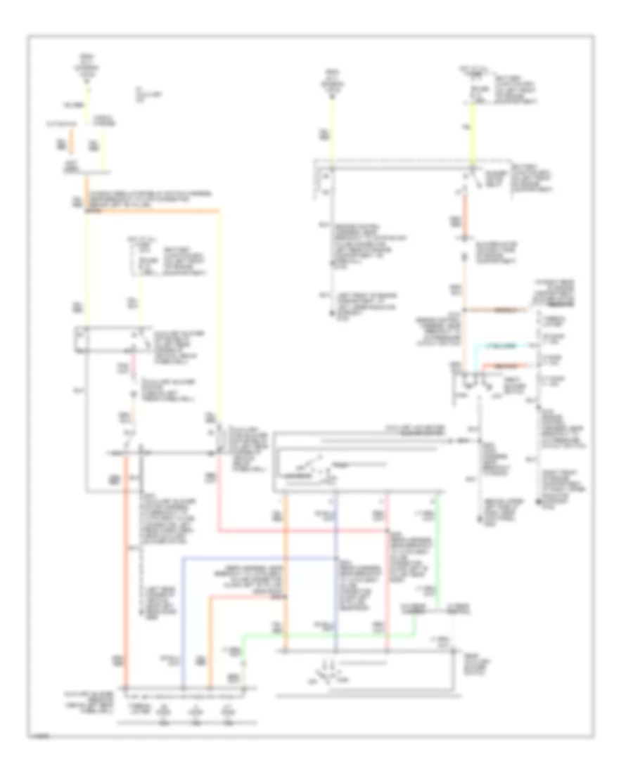
4.6L, Manual A/C Wiring Diagram, without Stripped Chassis for Ford Econoline E250 2001
List of elements for 4.6L, Manual A/C Wiring Diagram, without Stripped Chassis for Ford Econoline E250 2001:
- (below left side of dash, near left kick panel) g202
- (engine control harness) s142
- (engine control harness, near breakout to a/c pressure cutout switch) s143
- (engine control harness, near breakout to battery junction box) s110
- (engine control harness, near breakout to battery junction box) s111
- (lower dash harness, near breakout to brake pedal position (bpp) switch) s223
- (right front of engine compartment, at right upper radiator support) g109
- 87a
- A/c clutch cycling pressure switch (in right front of engine compartment)
- A/c clutch relay
- A/c compressor clutch
- A/c compressor clutch diode
- A/c on input signal
- A/c pressure cut-out switch (in right front of engine compartment)
- A/c relay ctrl
- Battery junction box (in left front of engine compartment)
- Blend door actuator (behind right side of dash, on a/c heater plenum)
- Central junction box (left side of dash, near kick panel)
- Def/flr
- Defrost
- Floor
- Function selector switch
- Fuse 15a
- Fuse 30a
- Hot at all times
- Hot in run
- Max a/c
- Norm a/c
- Note: pcm power relay energized w/ignition switch in run or start position
- Off
- Pcm power relay
- Powertrain control module (in left rear of engine compartment, near brake master cylinder)
- Red
- S166 (engine control harness, near breakout to 8 pin in-line connector, center of engine compartment)
- Temperature control switch
- To blower motor relay (diagram 2 of 2)
- To s400 (diagram 2 of 2)
- Vent
- Vent norm a/c
4.6L, Manual A/C Wiring Diagram, without Stripped Chassis for Ford Econoline E250 2001
List of elements for 4.6L, Manual A/C Wiring Diagram, without Stripped Chassis for Ford Econoline E250 2001:
- (behind upper left side of dash, near kick panel) g202
- (engine control harness, near breakout to 76 pin black in-line connector, left rear of engine compartment, on firewall) s122
- (in right rear of engine compartment) blower motor resistor
- (left front of engine compartment, at left upper radiator support) g108
- (left rear corner of vehicle, near left rear door) g999
- (not used)
- (rear harness, near breakout to 12 pin gray in-line connector, along left "b" pillar, near roof) s303
- (right front of engine compartment, at right upper radiator support) g109
- (window regulator relay switch harness, near breakout to 2 pin connector, behind left "b" pillar) s400
- .25 ohms +/- 10%
- .8 ohms +/- 10%
- 2.7 ohms +/- 10%
- 87a
- Auxiliary a/c-heater blower switch
- Auxiliary blower motor (above left rear wheelwell)
- Auxiliary blower motor relay (in left rear corner of vehicle, above wheelwell)
- Auxiliary blower resistor (above left rear wheelwell)
- Auxiliary high blower motor relay (in left rear corner of vehicle, above wheelwell)
- Battery junction box (in left front of engine compartment)
- Blower motor (on right side of engine compartment)
- Blower motor relay
- Cutaways
- From s111 (diagram 1 of 2)
- Front blower switch
- Fuse 50a
- High
- Hot at all times
- Low
- Low/rear
- Off
- Rear auxiliary blower switch
- S143 (engine control harness, near breakout to a/c pressure cutout switch)
- S144 (engine control harness, near breakout to a/c pressure cutout switch)
- S202 (main harness, near breakout to radio)
- S304 (rear harness, near breakout to 12 pin gray in-line connector, along left "b" pillar, near roof)
- S305 (rear harness, near breakout to 12 pin gray in-line connector, along left "b" pillar, near roof)
- S401 (auxiliary blower motor harness, in breakout to 12 pin gray in-line connector, left rear cargo area, near auxiliary blower motor)
- Thermal limiter
- Vans & wagons
- W/ auxiliary a/c
- W/ rear control
- W/o rear control
5.4L
5.4L, Manual A/C Wiring Diagram, with Stripped Chassis for Ford Econoline E250 2001
List of elements for 5.4L, Manual A/C Wiring Diagram, with Stripped Chassis for Ford Econoline E250 2001:
- (left rear of engine compartment, near master cylinder) g116
- (not used)
- (right rear of engine compartment) g105
- A/c compressor clutch
- A/c compressor clutch diode
- A/c demand
- A/c on input signal
- A/c switch
- Battery junction box (in left front of engine compartment)
- Blower motor
- Blower motor relay
- Breakout to fuel injector 6) s107
- C1001f
- Central junction box (left side of dash, near kick panel)
- Fuse 15a
- Fuse 50a
- Fused blower motor feed
- Hot at all times
- Hot in run
- Powertrain control module (in left rear of engine compartment, near brake master cylinder)
5.4L, Manual A/C Wiring Diagram, without Stripped Chassis for Ford Econoline E250 2001
List of elements for 5.4L, Manual A/C Wiring Diagram, without Stripped Chassis for Ford Econoline E250 2001:
- (below left side of dash, near left kick panel) g202
- (engine control harness, near breakout to injection pressure sensor (ips)) s189
- (lower dash harness, near breakout to brake pedal position (bpp) switch) s223
- (right front of engine compartment, at right upper radiator support) g109
- 5.4l, 5.4l ngv & 6.8l
- 7.3l di turbo diesel
- A/c clutch cycling pressure switch (in right front of engine compartment)
- A/c compressor clutch
- A/c compressor clutch diode
- A/c on input signal
- A/c pressure cut-out switch (in right front of engine compartment)
- Blend door actuator (behind right side of dash, on a/c heater plenum)
- Central junction box (left side of dash, near kick panel)
- Def/flr
- Defrost
- Floor
- Function selector switch
- Fuse 15a
- Hot in run
- Max a/c
- Norm a/c
- Off
- Powertrain control module (in left rear of engine compartment, near brake master cylinder)
- S111 (engine control harness, near breakout to battery junction box)
- S141 (engine control harness)
- S143 (engine control harness, near breakout to a/c pressure cutout switch)
- Temperature control switch
- To blower motor relay (diagram 2 of 2)
- To s400 (diagram 2 of 2)
- Vent
- Vent norm a/c
5.4L, Manual A/C Wiring Diagram, without Stripped Chassis for Ford Econoline E250 2001
List of elements for 5.4L, Manual A/C Wiring Diagram, without Stripped Chassis for Ford Econoline E250 2001:
- (behind upper left side of dash, near kick panel) g202
- (engine control harness, near breakout to 76 pin black in-line connector, left rear of engine compartment, on firewall) s122
- (in right rear of engine compartment) blower motor resistor
- (left front of engine compartment, at left upper radiator support) g108
- (left rear corner of vehicle, near left rear door) g999
- (not used)
- (rear harness, near breakout to 12 pin gray in-line connector, along left "b" pillar, near roof) s303
- (right front of engine compartment, at right upper radiator support) g109
- (window regulator relay switch harness, near breakout to 2 pin connector, behind left "b" pillar) s400
- .25 ohms +/- 10%
- .8 ohms +/- 10%
- 2.7 ohms +/- 10%
- 87a
- Auxiliary a/c-heater blower switch
- Auxiliary blower motor (above left rear wheelwell)
- Auxiliary blower motor relay (in left rear corner of vehicle, above wheelwell)
- Auxiliary blower resistor (above left rear wheelwell)
- Auxiliary high blower motor relay (in left rear corner of vehicle, above wheelwell)
- Battery junction box (in left front of engine compartment)
- Blower motor (on right side of engine compartment)
- Blower motor relay
- Cutaways
- From s111 (diagram 1 of 2)
- Front blower switch
- Fuse 50a
- High
- Hot at all times
- Low
- Low/rear
- Off
- Rear auxiliary blower switch
- S143 (engine control harness, near breakout to a/c pressure cutout switch)
- S144 (engine control harness, near breakout to a/c pressure cutout switch)
- S202 (main harness, near breakout to radio)
- S304 (rear harness, near breakout to 12 pin gray in-line connector, along left "b" pillar, near roof)
- S305 (rear harness, near breakout to 12 pin gray in-line connector, along left "b" pillar, near roof)
- S401 (auxiliary blower motor harness, in breakout to 12 pin gray in-line connector, left rear cargo area, near auxiliary blower motor)
- Thermal limiter
- Vans & wagons
- W/ auxiliary a/c
- W/ rear control
- W/o rear control

 Čeština
 Dansk
Dansk Deutsch
 Ελληνικά
 English
 English
 Español
 Suomi
Suomi Français
 Français
 עברית
עברית Hrvatski
 Magyar
 日本語
日本語 한국어
한국어 Nederlands
 Polski
 Português
 Português
 Română
 Русский
 Slovenčina
 Slovenščina
 Svenska
 Türkçe
 中文 (中国)