ANTI-LOCK BRAKES
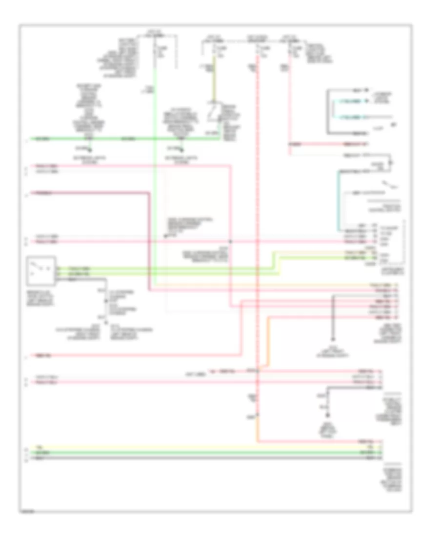
Anti-lock Brakes Wiring Diagram, with Stability Assist (1 of 2) for Ford Cutaway E250 2008
 https://portal-diagnostov.com/license.html
Automotive Electricians Portal FZCO
Automotive Electricians Portal FZCO
https://portal-diagnostov.com/license.html
https://portal-diagnostov.com/license.html
Automotive Electricians Portal FZCO
Automotive Electricians Portal FZCO
List of elements for Anti-lock Brakes Wiring Diagram, with Stability Assist (1 of 2) for Ford Cutaway E250 2008:
- (diesel: left side of engine compt) (gas: left front of engine compt) (stripped chassis: left front corner of engine compt) g105
- (except stripped chassis: below left side of dash) (stripped chassis: behind left side of dash) data link connector (dlc)
- (except stripped chassis: in main harness, near breakout to brake pedal position (bpp) switch) (stripped chassis: in main harness, near breakout to inertia fuel shutoff (ifs) switch) s269
- (in main harness, near breakout to inertia fuel shutoff (ifs) switch s228
- Abs control module (left front of engine compt)
- Angle a/1
- Angle b/2
- Battery junction box (bjb) (gas: left side of engine compt) (diesel: right front of engine compt) (stripped chassis: left front of engine compt)
- Bpp
- Brake pressure switch (left rear of eng compt)
- Brk press sw
- C175b
- C175e
- C175t
- Can +
- Can -
- Can 2 high
- Can 2 low
- Can+
- Can-
- Fuse 40a
- G122 (left rear of engine compt)
- Ground
- Hot at all times
- Left front wheel speed sensor (at left front wheel hub assembly)
- Left rear wheel speed sensor (at left rear wheel hub assembly)
- Lf_gnd
- Lf_sen
- Lr_gnd
- Lr_sen
- Nca
- Powertrain control module (pcm) (stripped chassis: right rear of engine compt) (diesel & gas: left rear of engine compt)
- Red/ pnk
- Red/pnk
- Ref
- Rf_gnd
- Rf_sen
- Right front wheel speed sensor (at right front wheel hub assembly)
- Right rear wheel speed sensor (at right rear wheel hub assembly)
- Rr_gnd
- Rr_sen
- S139 (in engine control sensor & fuel charge harness, near breakout for c192)
- Transmissions system
- Vbatt
- Vpwr
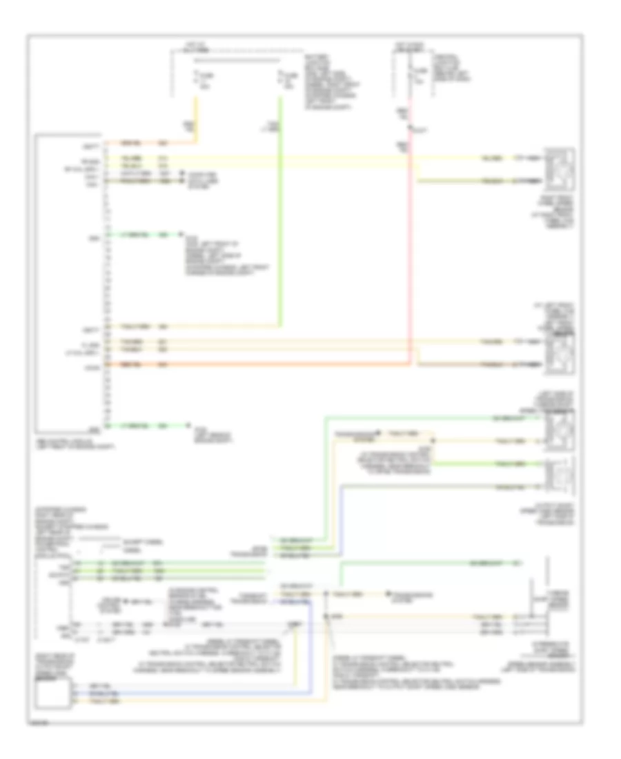
Anti-lock Brakes Wiring Diagram, with Stability Assist (2 of 2) for Ford Cutaway E250 2008
List of elements for Anti-lock Brakes Wiring Diagram, with Stability Assist (2 of 2) for Ford Cutaway E250 2008:
- (except gas: in engine control sensor harness, in breakout to c219) (gas: in engine control sensor harness, near breakout to g101) s174
- (gas: in engine control sensor harness, near breakout to c110) s146
- (in window regulator relay switch harness, near breakout to brake pedal position (bpp) switch) s224
- (not used)
- (w/ stripped chassis) s197
- Abs test connector (left front corner of engine compt)
- Battery junction box (bjb) (gas: left side of engine compt) (diesel: right front of engine compt) (stripped chassis: left front of engine compt)
- Brake fluid level switch (left rear of engine compt)
- Brake pedal position switch (on bracket, above brake pedal)
- C220a
- C220b
- Can+
- Can-
- Central junction box (cjb) (behind left side of dash)
- Exterior lights system
- Fuse 10a
- Fuse 15a
- Fuse 40a
- G107 (w/o stripped chassis) (right front of engine compt)
- G113 (w/ stripped chassis) (left rear of engine compt)
- G121 (left front of engine compt)
- G204 (behind left kick panel)
- Hot at all times
- Hot in run or start
- Illum
- Instrument cluster (ic)
- Interior lights system
- On/off ind
- S143 (w/o stripped chassis)
- S148 (gas: in engine control sensor harness, near breakout to c110)
- S205
- S216
- S235
- S260
- Stability control sensor cluster (under front passenger's seat)
- Steering position sensor (bottom of steering column)
- Tc ind
- Tc on/off
- Traction control switch
Anti-lock Brakes Wiring Diagram, without Stability Assist for Ford Cutaway E250 2008
List of elements for Anti-lock Brakes Wiring Diagram, without Stability Assist for Ford Cutaway E250 2008:
- (at left front wheel hub assembly) left front wheel speed sensor
- (diesel & torqshift diesel: in transmission control selector neutral switch harness, in breakout to c1148) (gas & torqshift: in transmission control selector neutral switch harness, near breakout to output shaft speed (oss) sensor)
- (diesel & torqshift diesel: in transmission control selector neutral switch harness, in breakout to c1148) (gas & torqshift: in transmission control selector neutral switch harness, near breakout to speed sensor assembly)
- (in engine control sensor & fuel charge harness, near breakout for c192) (gasoline) s139
- (left side of transmission) turbine shaft speed (tss) sensor
- (right rear of transmission) outputshaft speed (oss) sensor
- (stripped chassis: right rear of engine compt) (except stripped chassis: left rear of engine compt) powertrain control module (pcm)
- 4r75e transmission
- Abs control module (left front of engine compt)
- Battery junction box (bjb) (gas: left side of engine compt) (diesel: right front of engine compt) (stripped chassis: left front of engine compt)
- C1381t
- C175t
- Can +
- Can -
- Central junction box (cjb) (behind left side of dash)
- Computer data lines system
- Cruise control system
- Diesel
- Except diesel
- Fl gnd
- Fr gnd
- Fuse 10a
- Fuse 40a
- G105 (gas: left front of engine compt) (diesel: left side of engine compt) (stripped chassis: left front corner of engine compt)
- G122 (left rear of engine compt)
- Gnd
- Hot at all times
- Hot in run or start
- Intermediate shaft speed sensor
- Iss
- Lf whl spd +
- Nca
- Oss
- Output shaft speed (oss) sensor (left side of transmission)
- Rf whl spd +
- Right front wheel speed sensor (at right front wheel hub assembly)
- S1037
- S1077
- S198
- S198 (in transmission control selector neutral switch harness, near breakout to 4r75e transmission)
- Sig rtn
- Speed sensor assembly (left side of transmission)
- Torqshift transmission
- Transmissions system
- Tss
- Turbine shaft speed sensor
- Vbatt
- Vpwr
- Vref

 Čeština
 Dansk
Dansk Deutsch
 Ελληνικά
 English
 English
 Español
 Suomi
Suomi Français
 Français
 עברית
עברית Hrvatski
 Magyar
 日本語
日本語 한국어
한국어 Nederlands
 Polski
 Português
 Português
 Română
 Русский
 Slovenčina
 Slovenščina
 Svenska
 Türkçe
 中文 (中国)