COOLING FAN
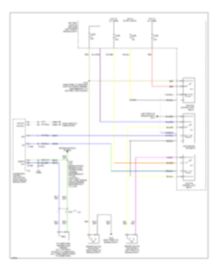
Cooling Fan Wiring Diagram for Ford Flex SE 2014
List of elements for Cooling Fan Wiring Diagram for Ford Flex SE 2014:
- (left front of engine compt) g101
- 3.5l
- 3.5l turbo
- Battery junction box (bjb) (left side of engine compt)
- C1381b
- C1381e
- C175b
- C175e
- C192
- Cec01
- Cec02
- Cht
- Computer data lines system
- Cylinder head temperature sensor (3.5l: top front of right cylinder head) (3.5l turbo: rear of right cylinder head)
- Engine controls system
- Engine cooling fan motor 1 (right front of engine compt)
- Engine cooling fan motor 2 (left front of engine compt)
- Fan control (fc) relay
- Fuse 15a
- Fuse 25a
- Fuse 40a
- G100 (right front of engine compt)
- Hfc
- High fan control (hfc) relay
- Hot at all times
- Hot in start or run
- Hs can +
- Hs can -
- Lfc
- Low fan control (lfc) relay
- Powertrain control module (pcm) (right rear of engine compt)
- Re405
- Red
- S108
- S122 (dash panel to headlamp junction wiring harness, near breakout to battery junction box)
- S126 (3.5l: engine control sensor & fuel charge wiring harness, near breakout to fuel injector 3) (3.5l turbo: engine wiring harness, near breakout to c1045)
- Sigrtn
- Vdb04
- Vdb05
- Ve712
 Čeština
 Dansk
Dansk Deutsch
 Ελληνικά
 English
 English
 Español
 Suomi
Suomi Français
 Français
 עברית
עברית Hrvatski
 Magyar
 日本語
日本語 한국어
한국어 Nederlands
 Polski
 Português
 Português
 Română
 Русский
 Slovenčina
 Slovenščina
 Svenska
 Türkçe
 中文 (中国)
 Italiano