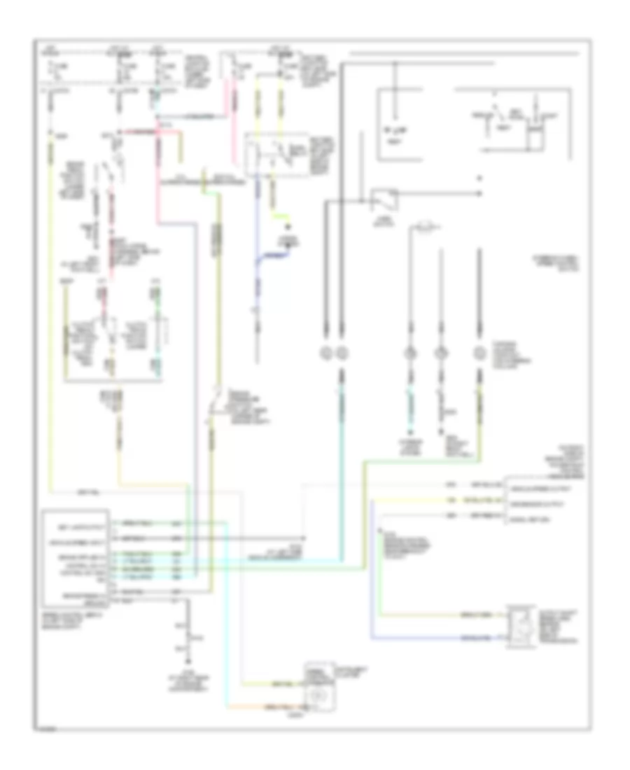
CRUISE CONTROL
Cruise Control Wiring Diagram for Ford Pickup Heritage F150 2004
List of elements for Cruise Control Wiring Diagram for Ford Pickup Heritage F150 2004:
- (main wiring harness, behind left side of dash)
- (on right side of engine compt)
- 5.4l supercharged
- A/t
- Accel
- Air bag sliding contact (on steering column)
- Battery junction box (bjb) (in left side of engine compt)
- Brake pedal position switch (under left side of dash)
- Brake press in
- Brake pressure switch (in left rear corner of engine compt)
- C220a
- C270a
- C270b
- Central junction box (cjb) (under left side of dash)
- Clutch pedal position switch (on clutch pedal arm)
- Clutch triple function switch jumper
- Coast
- Control sw gnd
- Control sw in
- Esof
- Exc 5.4l supercharged
- Fuse 15a
- Fuse 20a
- Fuse 2a
- Fuse 5a
- G102 (at right rear of engine compartment)
- G200 (in right front footwell)
- G201 (in left front footwell)
- Ground
- Horn relay
- Horn switch
- Horns system
- Hot at all times
- Hot in run
- Ign
- Instrument cluster
- Interior lights system
- M/t
- Nca
- Off
- Oss sensor output
- Output shaft speed (oss) sensor (on left side of transmission)
- Powertrain control module (pcm)
- Rest
- Resume
- S102
- S112
- S138 (engine control sensor harness, near breakout to g101)
- S143 (at left side vehicle underbody)
- S208
- S265
- S274
- Set lamp output
- Set/
- Signal return
- Speed control indicator
- Speed control servo (in left side of engine compt)
- Steering wheel/ speed control switch
- Vehicle speed input
- Vehicle speed output
 Čeština
 Dansk
Dansk Deutsch
 Ελληνικά
 English
 English
 Español
 Suomi
Suomi Français
 Français
 עברית
עברית Hrvatski
 Magyar
 日本語
日本語 한국어
한국어 Nederlands
 Polski
 Português
 Português
 Română
 Русский
 Slovenčina
 Slovenščina
 Svenska
 Türkçe
 中文 (中国)
 Italiano