ENGINE PERFORMANCE
5.4L
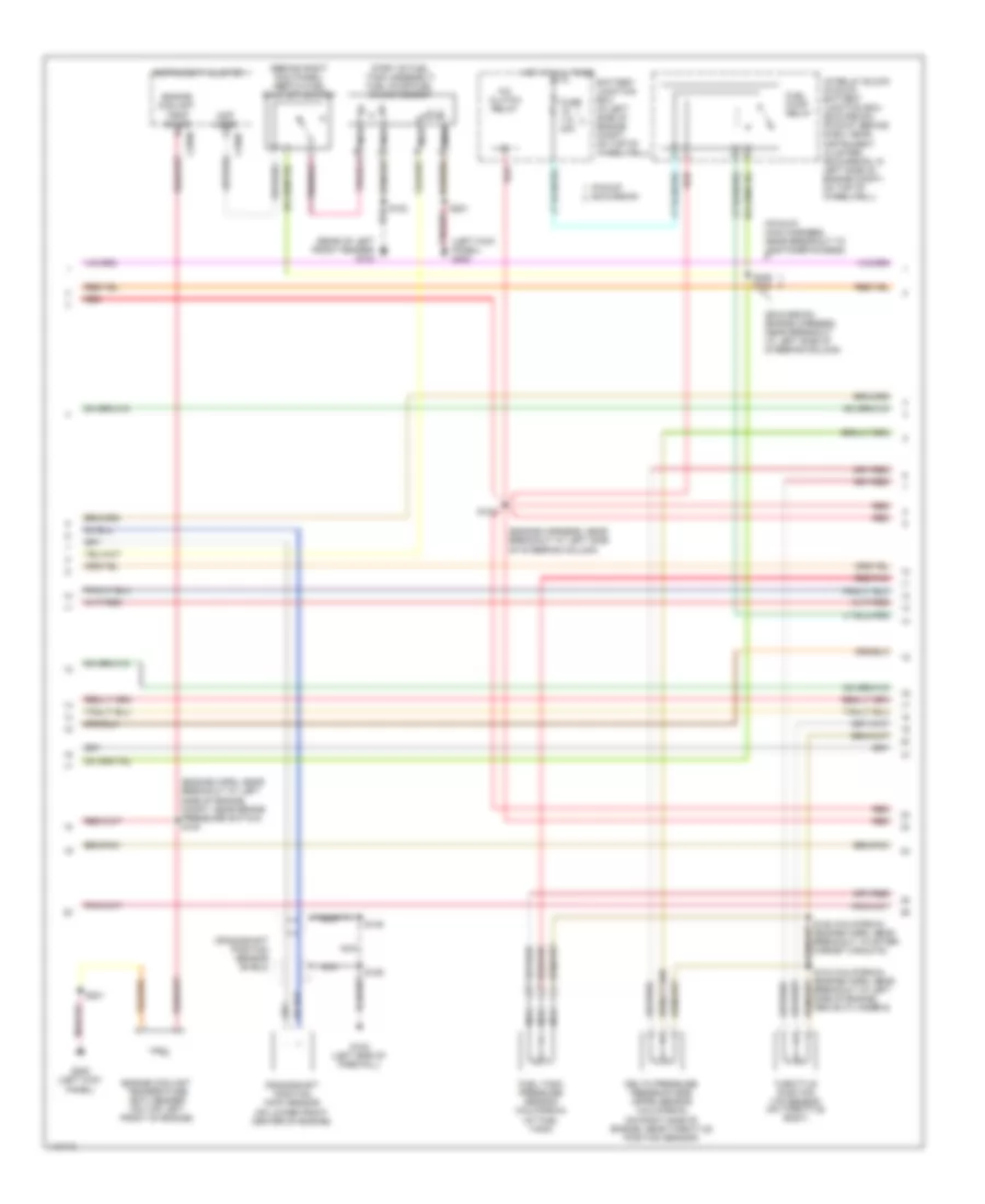
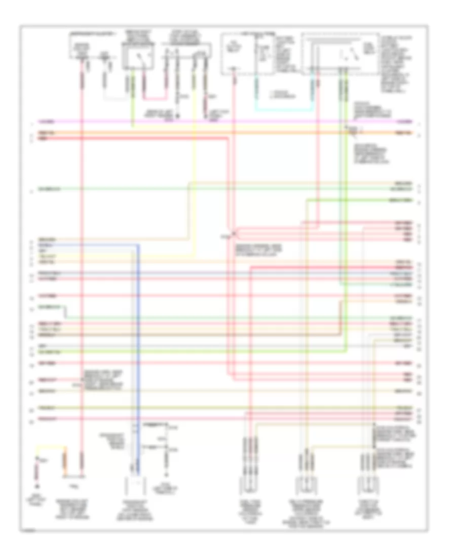
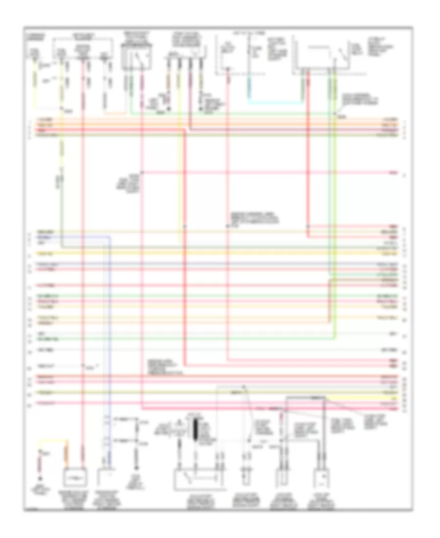
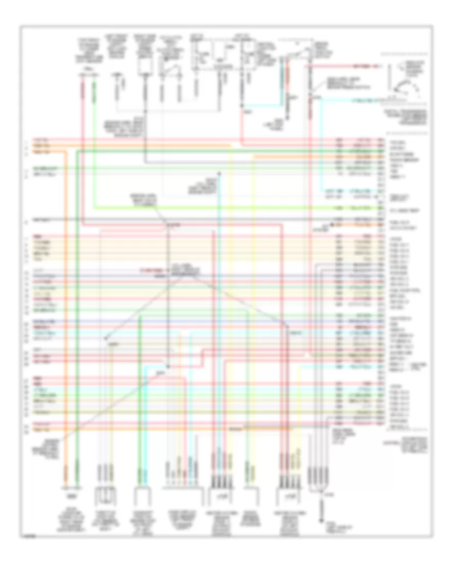
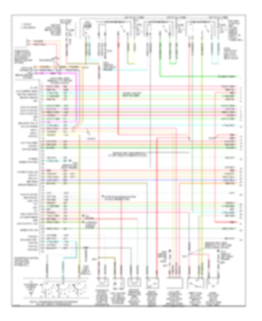
5.4L, Engine Performance Wiring Diagram (1 of 4) for Ford Cab & Chassis F350 Super Duty 2001
 https://portal-diagnostov.com/license.html
Automotive Electricians Portal FZCO
Automotive Electricians Portal FZCO
https://portal-diagnostov.com/license.html
https://portal-diagnostov.com/license.html
Automotive Electricians Portal FZCO
Automotive Electricians Portal FZCO
List of elements for 5.4L, Engine Performance Wiring Diagram (1 of 4) for Ford Cab & Chassis F350 Super Duty 2001:
- (engine harn, near breakout at left side of engine compt)
- (engine sensor harn, near breakout at right side of engine, above cylinder 3)
- (left kick panel)
- (main harn, near breakout at center of dash, on dlc)
- (not used)
- (pickup)
- (rear of left front fender)
- 4x4 high/low indicator switch
- 4x4 low ind sw
- 4x4 low ind
- A/c press sw
- A/c system
- Anti-theft system
- Battery junction box (in left side of engine compt, on top of wheelwell)
- C242b
- C250b
- C250c
- Ccs
- Central junction box (behind lower left side of dash)
- Ckp(+)
- Ckp(-)
- Coil on plug
- Cust access
- Customer access
- Data link (+)
- Data link (-)
- Data link connector (dlc) (behind center of dash)
- Data output
- Diag grd
- Digital transmission range (dtr) sensor (on left side of transmission)
- Egr sol
- Fuel gauge
- Fuel gauge in
- Fuel pump mon
- Fuse 10a
- Fuse 20a
- Fuse 30a
- G102 (left side of firewall)
- G104
- G200
- Hego 12
- Hot at all times
- Hot in run or start
- Iat
- Ign coil 1
- Ign coil 3
- Ign coil 5
- Ign coil 6
- Instrument cluster
- Knock sensor
- Maf
- Mil ind
- Nca
- Not used
- O/d off ind
- Overdrive cancel switch (a/t)
- Overhead console
- Pcm power diode
- Pcm power relay
- Pickup excursion
- Powertrain control module (pcm) (on left side of firewall)
- Pwr gnd
- R n
- Radio noise capacitor (on left side of engine)
- Radio noise capacitor (on right side of engine)
- Red
- Reprog pwr
- S102
- S105
- S106
- S129 (calif)
- S130 (engine harn, near breakout at throttle body)
- S135
- S179
- S201
- S208
- S213 s271
- S284
- S286
- Shift sol 1
- Shift sol 2
- Tach
- Tcs
- Temp output
- Tft
- To dtr sensor (diagram 4 of 4)
- Tr1
- Tr2
- Tr4
- Trans ctrl ind
- Transmission control switch
- Vss (-)
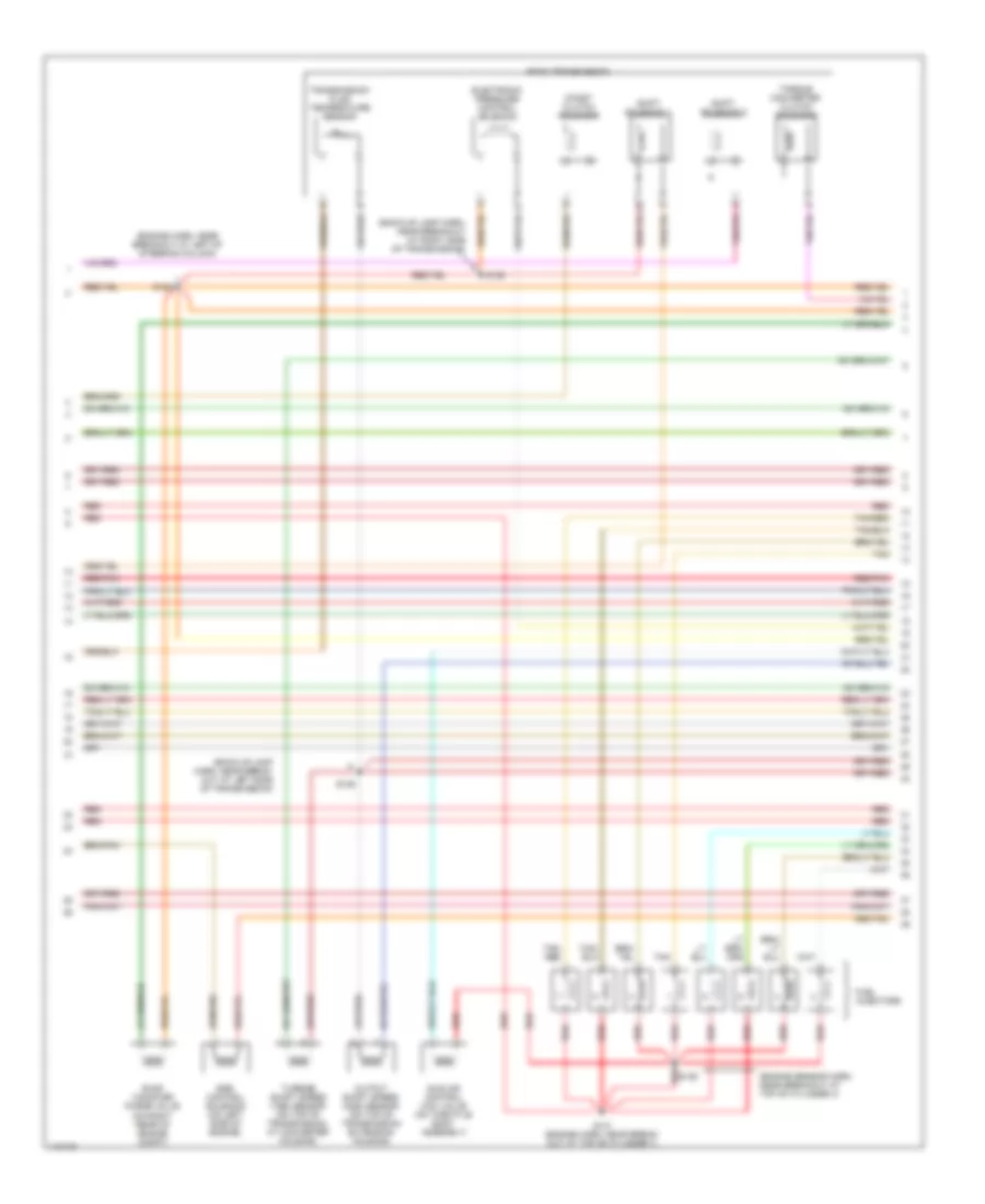
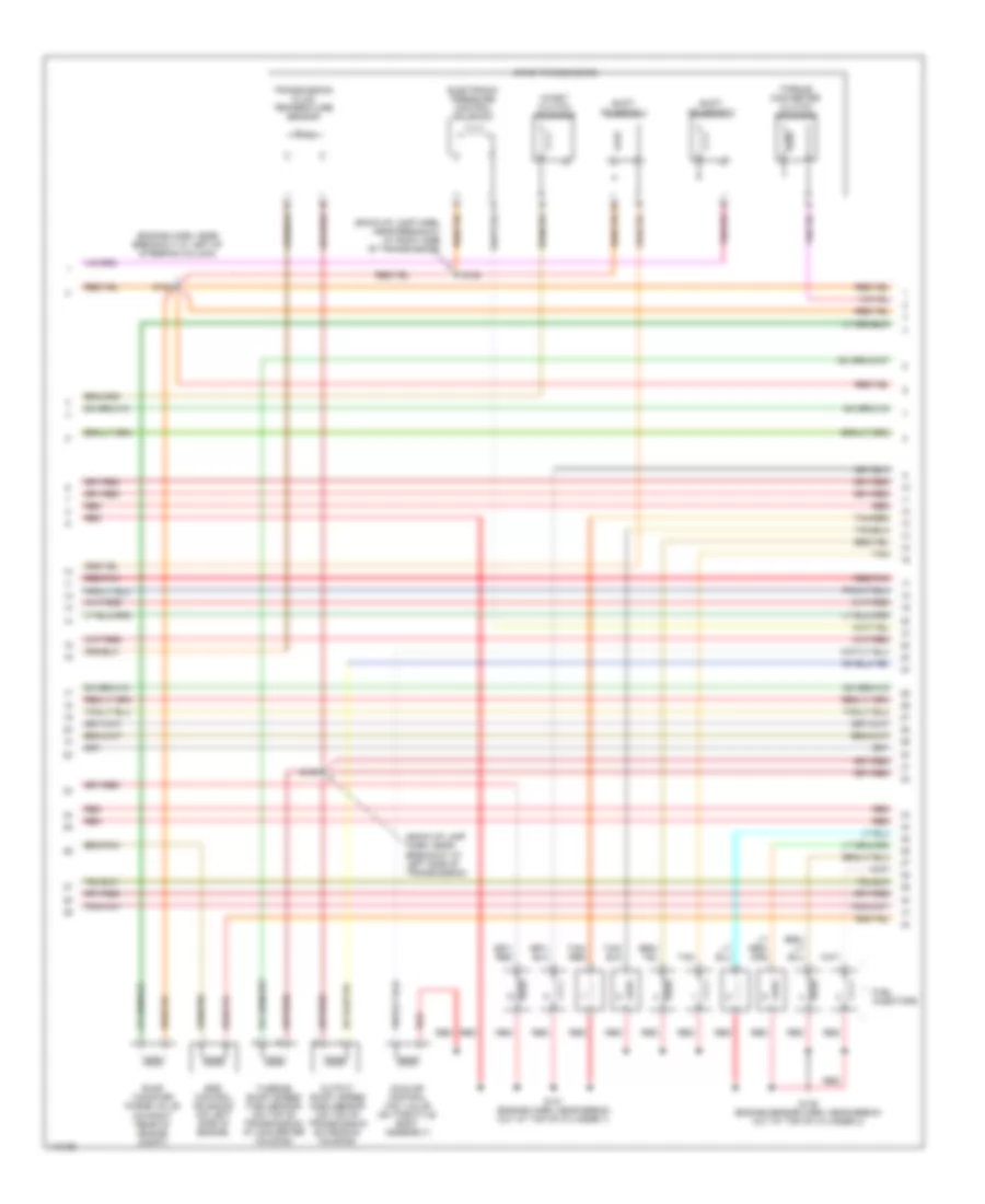
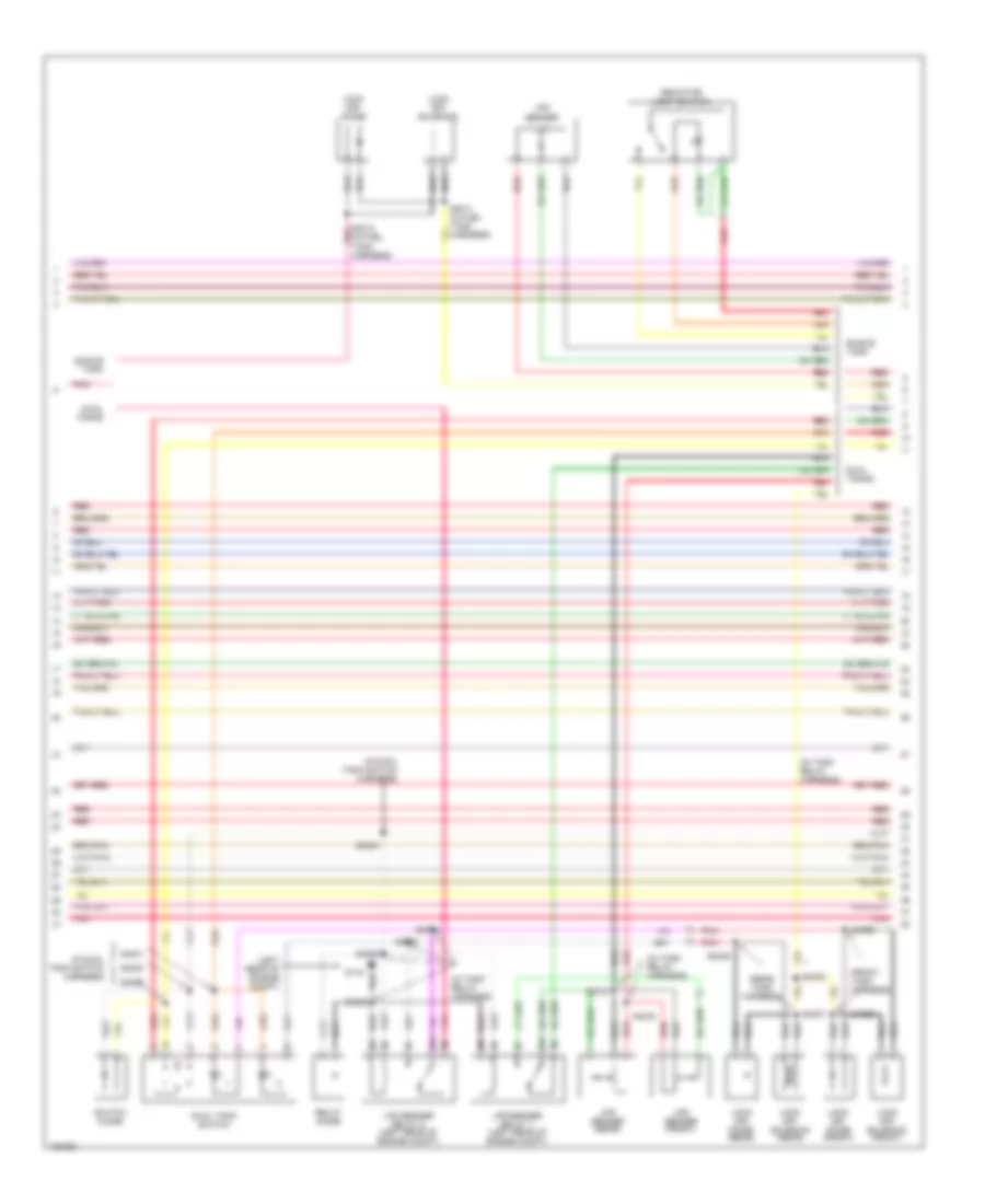
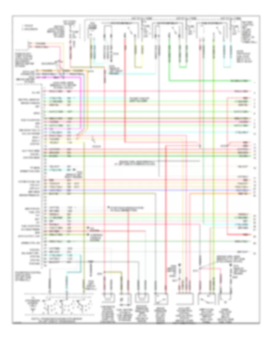
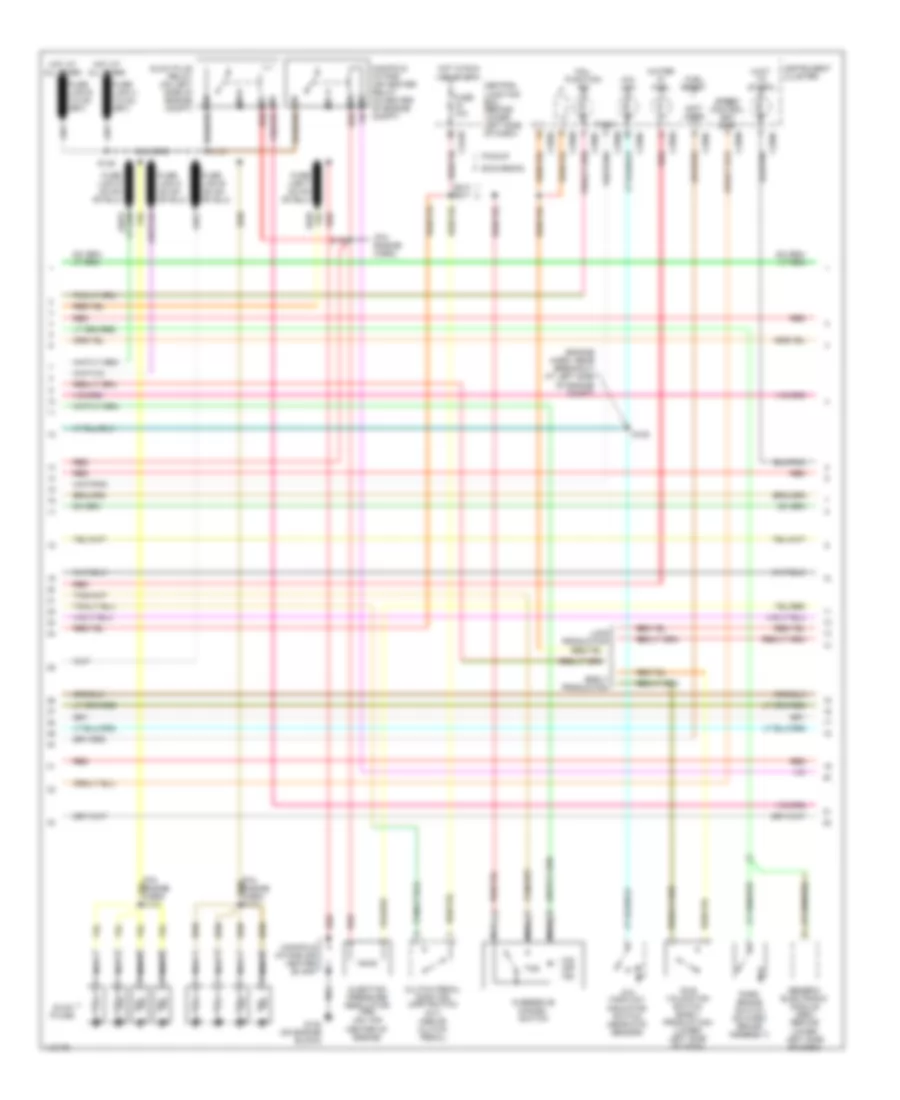
5.4L, Engine Performance Wiring Diagram (2 of 4) for Ford Cab & Chassis F350 Super Duty 2001
List of elements for 5.4L, Engine Performance Wiring Diagram (2 of 4) for Ford Cab & Chassis F350 Super Duty 2001:
- (behind right kick panel) inertia fuel shut-off switch
- (engine harn, near breakout at left side of engine compt, near brake pressure switch) s104
- (engine harness, near breakout at left side of steering column)
- (excursion: engine harness, near breakout at left side of steering column)
- (left kick panel) g200
- (not used)
- (part of fuel tank assembly) fuel pump/fuel gauge sender
- (pickup: main harness, near breakout to customer access)
- (rear of left front fender) g104
- A/c clutch relay
- Battery junction box (in left side of engine compt, on top of wheelwell)
- C250b
- C250c
- Crankshaft position (ckp) sensor (on lower front center of engine)
- Crankshaft position sensor shield
- Delta pressure feedback egr (dpfe) sensor (california) (on right side of engine, near throttle position sensor)
- Engine coolant temp gauge
- Engine coolant temperature (ect) sender (on top left front of engine)
- Fuel pump relay
- Fuel tank pressure sensor (california) (at fuel tank)
- Fuse 20a
- G102 (left side of firewall)
- G200 (left kick panel)
- Hot at all times
- I/p relay block (pickup) battery junction box (excursion) (pickup: behind dash, near instrument cluster) (excursion: in left side of engine compt, on top of wheelwell)
- Instrument cluster
- Nca
- Pickup excursion
- Red
- Red/pnk
- S102
- S106
- S123
- S128 (california) (engine harn, near breakout to after- market circuits)
- S133 (california) (engine harn, near breakout at left side of engine, above cylinder 6)
- S145
- S201
- S226 s164
- Throttle position (tp) sensor (on throttle body)
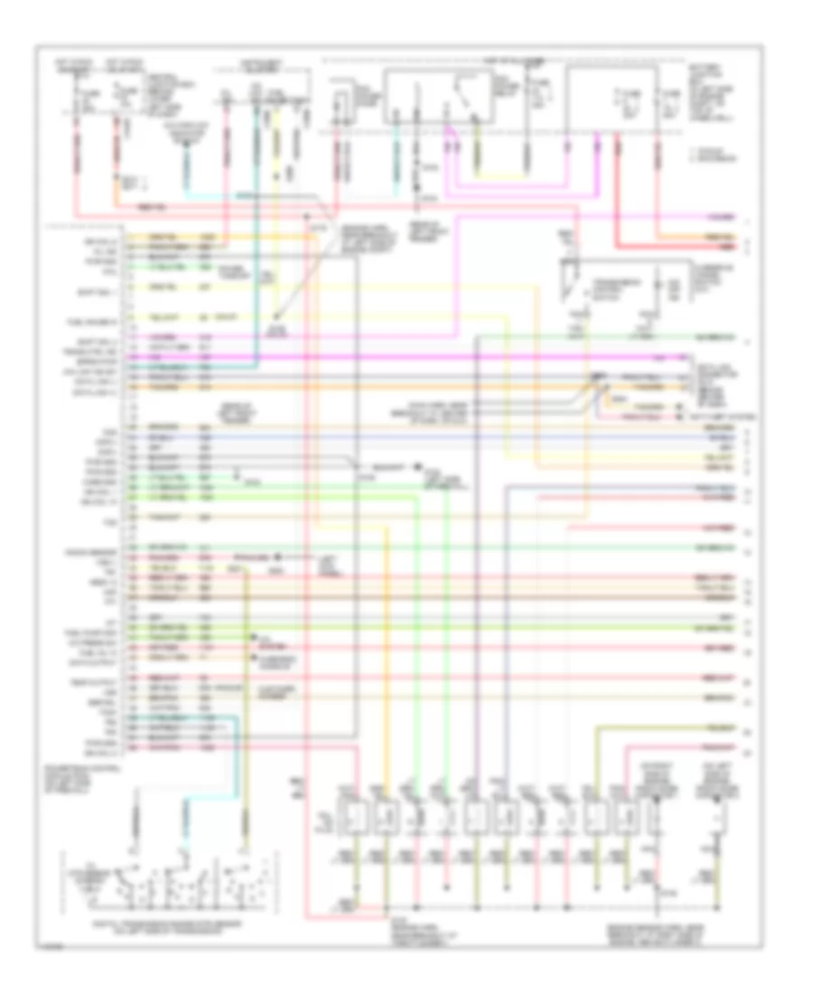
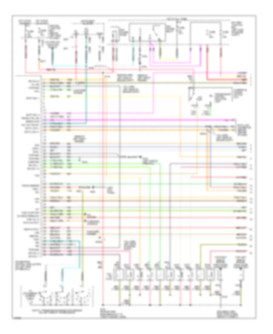
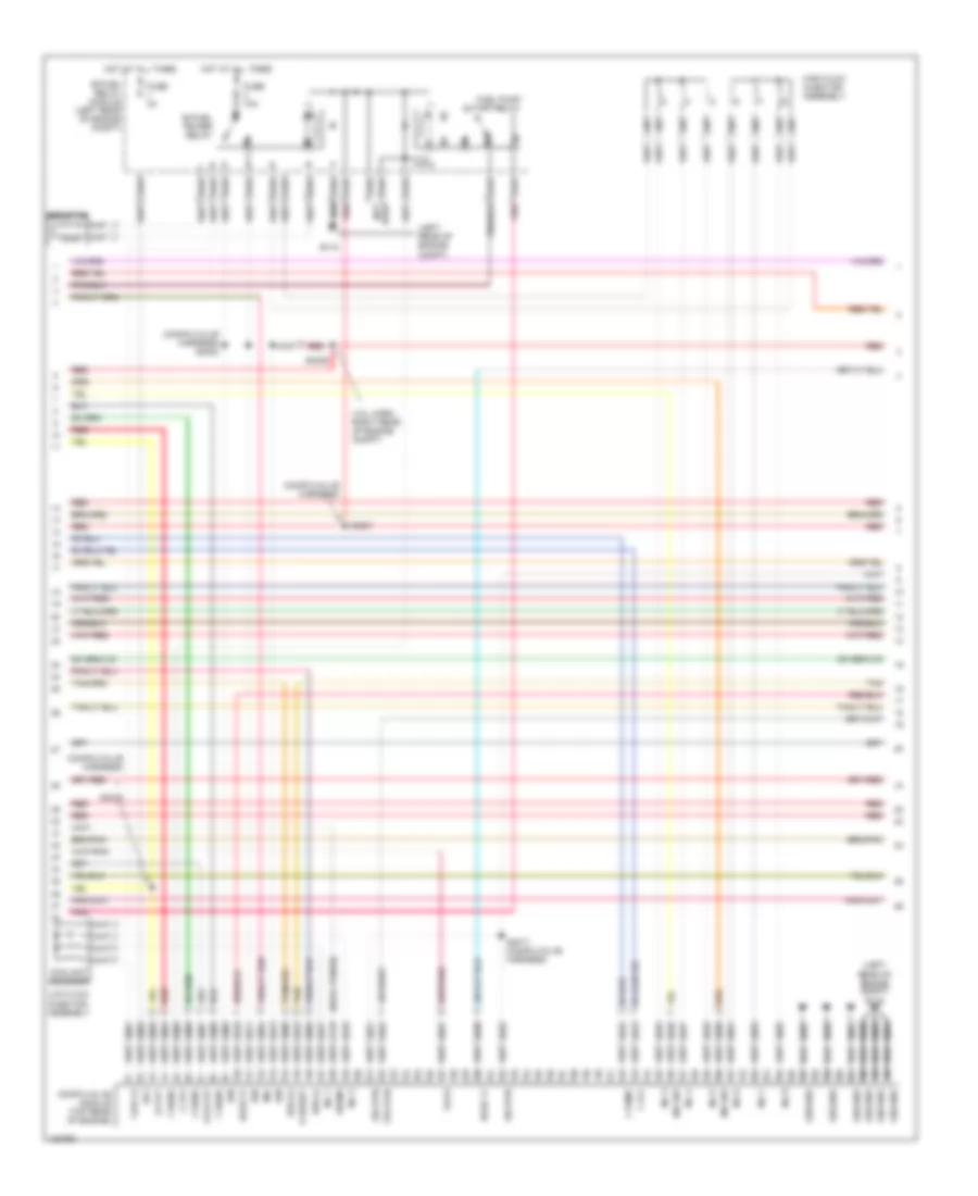
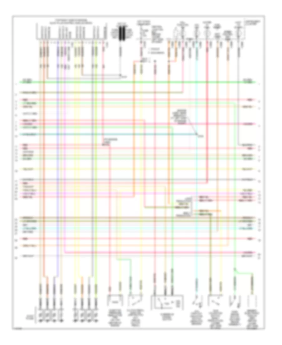
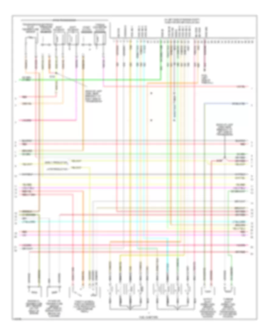
5.4L, Engine Performance Wiring Diagram (3 of 4) for Ford Cab & Chassis F350 Super Duty 2001
List of elements for 5.4L, Engine Performance Wiring Diagram (3 of 4) for Ford Cab & Chassis F350 Super Duty 2001:
- (back-up lamp harn, near break- out at left side of transmission)
- (back-up lamp harn, near breakout at right side of transmission)
- (engine harn, near breakout at left of steering column)
- (engine sensor harn, near breakout at top of cylinder 3)
- (on right rear of engine compt)
- 4r100 transmission
- Coast clutch solenoid
- Egr control solenoid (on left side of engine)
- Electronic pressure control solenoid
- Evap canister purge valve
- Fuel injectors
- Idle air control (iac) valve (on throttle body assembly)
- Output shaft speed (oss) sensor (on top of transmission extension housing)
- Red
- Red/pnk
- S122
- S131 (engine harn, near break- out at top of cylinder 7)
- S136
- S138
- S139
- Shift solenoid 1
- Shift solenoid 2
- Tan
- Tan/ red
- Tan/red
- Torque converter clutch solenoid
- Transmission fluid temperature sensor
- Turbine shaft speed (tss) sensor (on top of transmission, at converter housing)
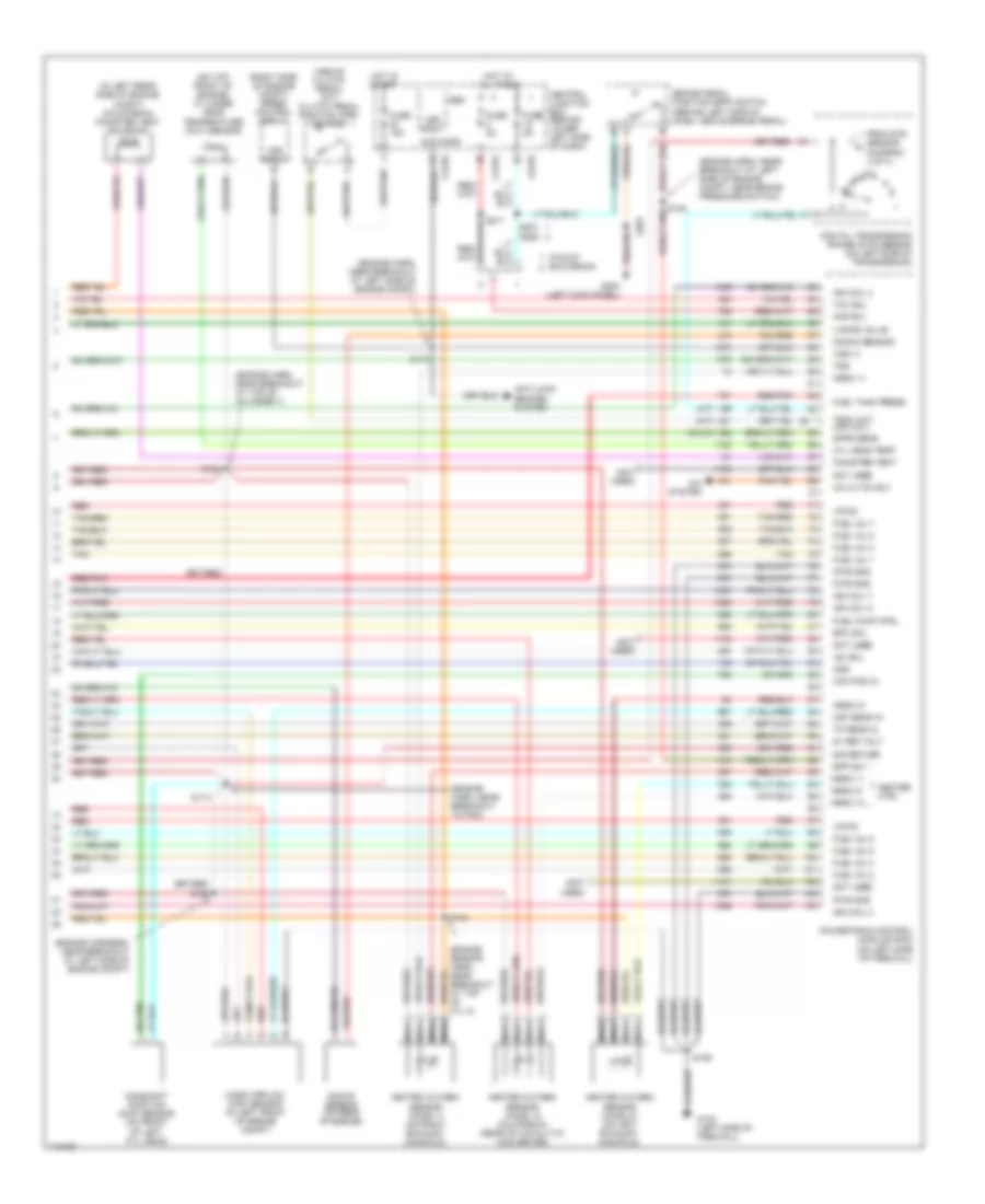
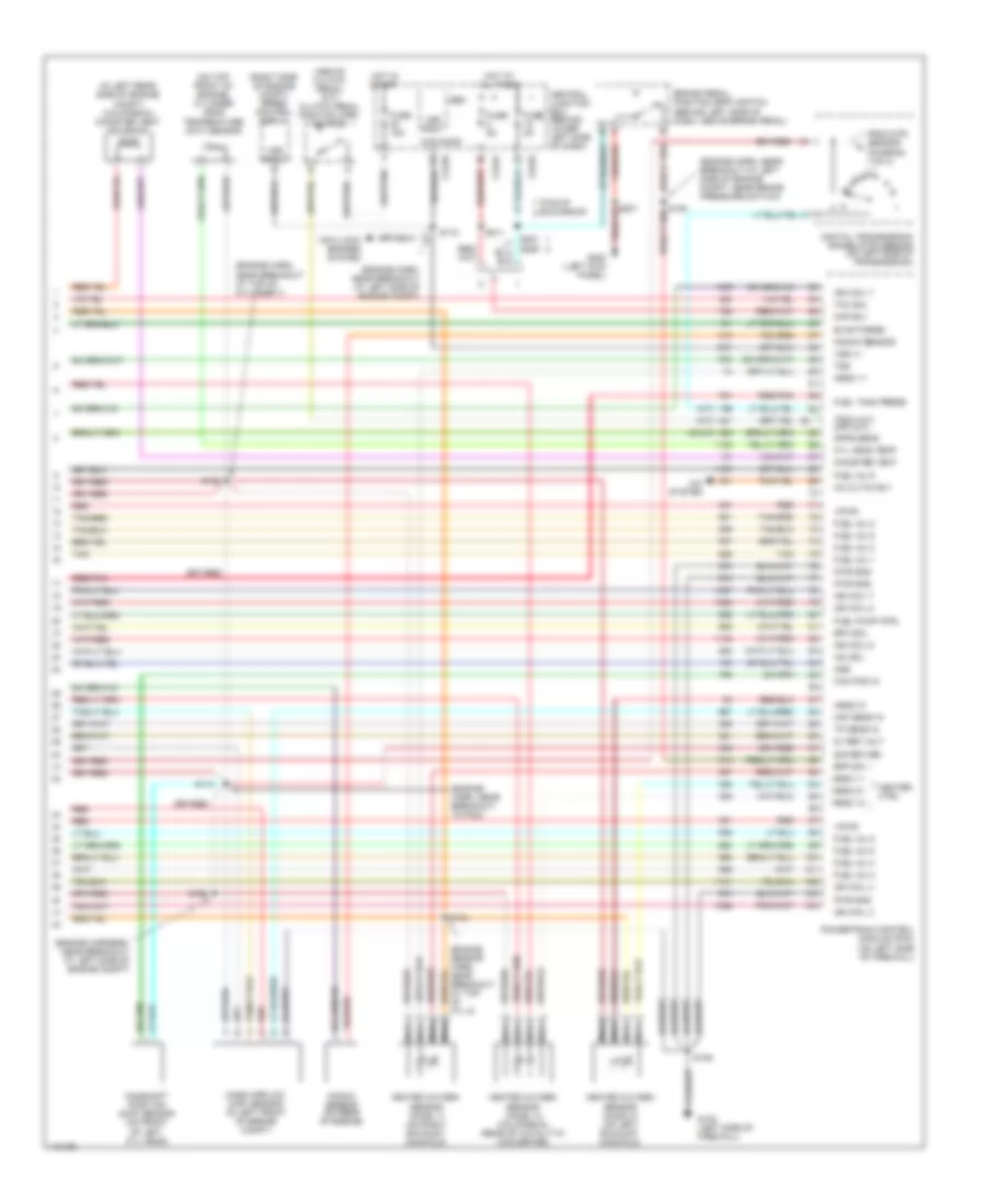
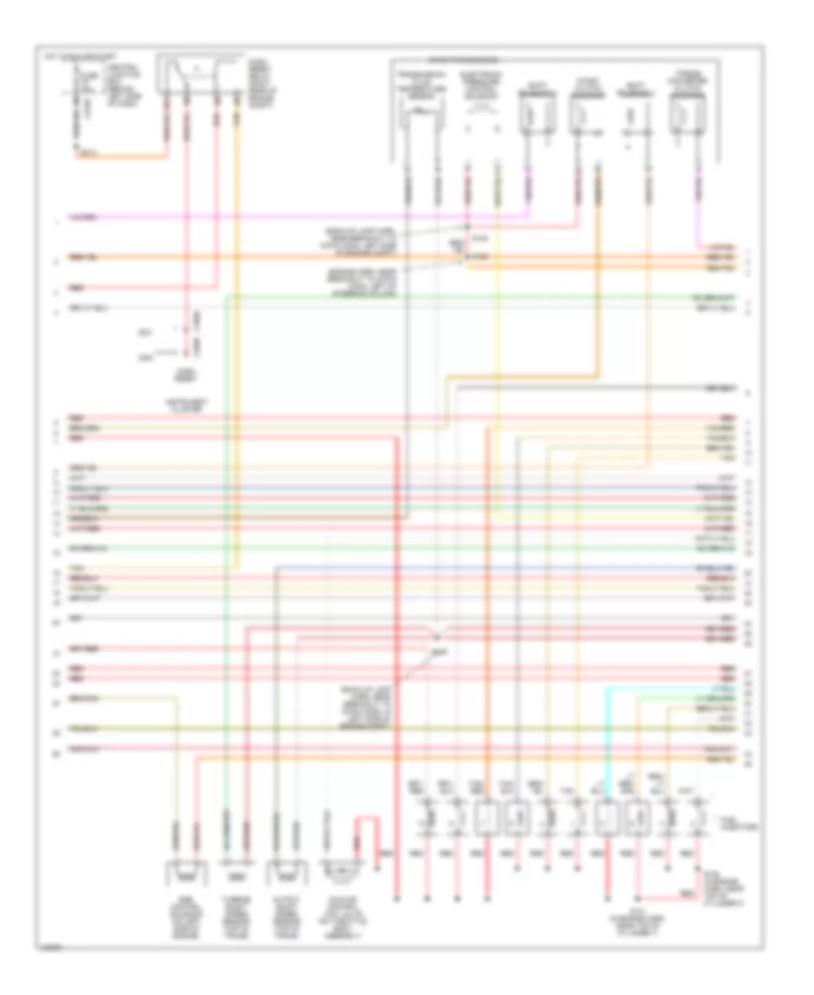
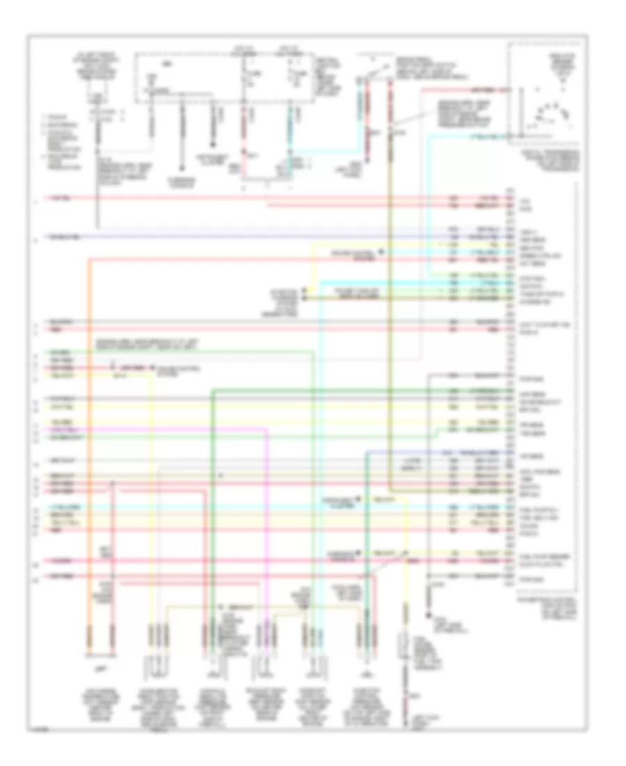
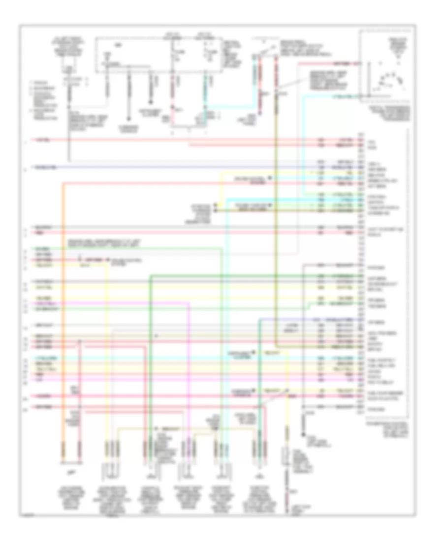
5.4L, Engine Performance Wiring Diagram (4 of 4) for Ford Cab & Chassis F350 Super Duty 2001
List of elements for 5.4L, Engine Performance Wiring Diagram (4 of 4) for Ford Cab & Chassis F350 Super Duty 2001:
- (a/t)
- (above clutch pedal) (m/t) clutch pedal position (cpp) switch
- (calif)
- (engine harn, near breakout at left side of engine compt)
- (engine harn, near breakout at left side of engine compt, near brake pressure switch)
- (engine harn, near breakout at top of cylinder 7)
- (engine harn, near breakout to pcm)
- (engine harness, near breakout at left side of engine compt)
- (in left rear side of engine compt) (california) canister vent solenoid
- (m/t)
- (not used)
- (on top front of engine) cylinder head temperature (cht) sensor
- (right side of engine compt) speed control servo
- 5v ref volt
- A/c cltch rly
- A/c system
- Anti-lock brakes system
- Bpp sw
- Brake pedal position (bpp) switch (behind left side of dash, above brake pedal)
- C240d
- C242a
- C242b
- Cam pos in
- Camshaft position (cmp) sensor (on front of left cyl head)
- Canister vent
- Central junction box (behind lower left side of dash)
- Cyl 8)
- Cyl head temp
- Digital transmission range (dtr) sensor (on left side of transmission)
- Dpfe sens
- Epc sol
- From dtr sensor (diagram 1 of 4)
- Fuel inj 1
- Fuel inj 2
- Fuel inj 3
- Fuel inj 4
- Fuel inj 5
- Fuel inj 6
- Fuel inj 7
- Fuel inj 8
- Fuel pump ctrl
- Fuel tank press
- Fuse 15a
- Fuse 5a
- G102 (left side of firewall)
- G200 (left kick panel)
- Gem
- Heated oxygen sensor (ho2s) 11 (on right exhaust manifold)
- Heated oxygen sensor (ho2s) 12 (california) (rear of catalytic converter)
- Heated oxygen sensor (ho2s) 21 (on left exhaust manifold)
- Heater ctrl
- Hego 11
- Hego 12
- Hego 21
- Hot at all times
- Hot in start
- Iac sol
- Ign coil 2
- Ign coil 4
- Ign coil 7
- Ign coil 8
- Kap b(+)
- Knock sensor
- Knock sensor (on rear of engine)
- Maf sens in
- Mass airflow (maf) sensor (in left front of engine compt)
- Nca
- Not used
- Oss
- Pickup excursion
- Powertrain control module (pcm) (on left side of firewall)
- Pwr gnd
- Red
- Red/pnk
- S106
- S114
- S115
- S129
- S132
- S134
- S211
- S221
- S288
- Sig return
- Tan
- Tan/red
- Tcc sol
- Tp sens in
- Tr3a (a/t) cpp (m/t)
- Tss
- Vapor valve
- Vpwr
- Vss (+)
- Vss input
6.8L
6.8L, Engine Performance Wiring Diagram (1 of 4) for Ford Cab & Chassis F350 Super Duty 2001
List of elements for 6.8L, Engine Performance Wiring Diagram (1 of 4) for Ford Cab & Chassis F350 Super Duty 2001:
- (calif)
- (engine harn, near breakout at left side of engine compt)
- (engine sensor harn, near breakout at right side of engine, above cylinder 3)
- (left kick panel)
- (main harn, near breakout at center of dash, on dlc)
- (on left side of engine) radio noise capacitor 2
- (on right side of engine) radio noise capacitor 1
- (pickup)
- (rear of left front fender)
- 4x4 high/low indicator switch
- 4x4 low ind sw
- 4x4 low ind
- A/c press sw
- A/c system
- Anti-theft system
- Battery junction box (in left side of engine compt, on top of wheelwell)
- C242b
- C250b
- C250c
- Case gnd
- Ccs
- Central junction box (behind lower left side of dash)
- Ckp(+)
- Ckp(-)
- Coil on plug
- Customer access
- Data link (+)
- Data link (-)
- Data link connector (dlc) (behind center of dash)
- Data output
- Digital transmission range (dtr) sensor (on left side of transmission)
- Egr sol
- Eprom pwr
- Fuel gauge
- Fuel gauge in
- Fuel inj 10
- Fuel pump mon
- Fuse 10a
- Fuse 20a
- Fuse 30a
- G102 (left side of firewall)
- G104
- G200
- Hego 12
- Hot at all times
- Hot in run or start
- Iat
- Ign coil 1
- Ign coil 10
- Ign coil 5
- Ign coil 6
- Instrument cluster
- Knock sensor
- Maf
- Mil ind
- Nca
- O/d off ind
- Overdrive cancel switch (a/t)
- Overhead console
- Pcm power diode
- Pcm power relay
- Pickup excursion
- Power take-off
- Powertrain control module (pcm) (on left side of firewall)
- Pto
- Pwr gnd
- R n
- Red
- S102
- S105
- S106
- S129 (calif)
- S130 (engine harn, near breakout at throttle body)
- S135
- S179
- S201
- S208
- S213 s271
- S284
- S286
- Shift sol 1
- Shift sol 2
- Tach
- Tcs
- Temp output
- Tft
- To dtr sensor (diagram 4 of 4)
- Tr1
- Tr2
- Tr4
- Trans ctrl ind
- Transmission control switch
- Vss
- Vss (-)
6.8L, Engine Performance Wiring Diagram (2 of 4) for Ford Cab & Chassis F350 Super Duty 2001
List of elements for 6.8L, Engine Performance Wiring Diagram (2 of 4) for Ford Cab & Chassis F350 Super Duty 2001:
- (behind right kick panel) inertia fuel shut-off switch
- (engine harn, near breakout at left side of engine compt, near brake s104 pressure switch)
- (engine harness, near breakout at left side of steering column)
- (excursion: engine harness, near breakout at left side of steering column)
- (left kick panel) g200
- (not used)
- (part of fuel tank assembly) fuel pump/fuel gauge sender
- (pickup: main harness, near breakout to customer access)
- (rear of left front fender) g104
- A/c clutch relay
- Battery junction box (in left side of engine compt, on top of wheelwell)
- C250b
- C250c
- Crankshaft position (ckp) sensor (on lower front center of engine)
- Crankshaft position sensor shield
- Delta pressure feedback egr (dpfe) sensor (california) (on right side of engine, near throttle position sensor)
- Engine coolant temp gauge
- Engine coolant temperature (ect) sender (on top left front of engine)
- Fuel pump relay
- Fuel tank pressure sensor (california) (at fuel tank)
- Fuse 20a
- G102 (left side of firewall)
- G200 (left kick panel)
- Hot at all times
- I/p relay block (pickup) battery junction box (excursion) (pickup: behind dash, near instrument cluster) (excursion: in left side of engine compt, on top of wheelwell)
- Instrument cluster
- Nca
- Pickup excursion
- Red
- Red/pnk
- S102
- S106
- S123
- S128 (california) (engine harn, near breakout to after- market circuits)
- S133 (california) (engine harn, near breakout at left side of engine, above cylinder 6)
- S145
- S201
- S226 s164
- Throttle position (tp) sensor (on throttle body)
6.8L, Engine Performance Wiring Diagram (3 of 4) for Ford Cab & Chassis F350 Super Duty 2001
List of elements for 6.8L, Engine Performance Wiring Diagram (3 of 4) for Ford Cab & Chassis F350 Super Duty 2001:
- (back-up lamp harn, near breakout at left side of transmission)
- (back-up lamp harn, near breakout at right side of transmission)
- (engine harn, near breakout at left of steering column)
- (on right rear of engine compt)
- 4r100 transmission
- Coast clutch solenoid
- Egr control solenoid (on left side of engine)
- Electronic pressure control solenoid
- Evap canister purge valve
- Fuel injectors
- Idle air control (iac) valve (on throttle body assembly)
- Output shaft speed (oss) sensor (on top of transmission extension housing)
- Red
- Red/pnk
- S122
- S131 (engine harn, near break- out at top of cylinder 7)
- S136 (engine sensor harn, near break- out at top of cylinder 3)
- S138
- S139
- Shift solenoid 1
- Shift solenoid 2
- Tan
- Tan/ red
- Tan/red
- Torque converter clutch solenoid
- Transmission fluid temperature sensor
- Turbine shaft speed (tss) sensor (on top of transmission, at converter housing)
6.8L, Engine Performance Wiring Diagram (4 of 4) for Ford Cab & Chassis F350 Super Duty 2001
List of elements for 6.8L, Engine Performance Wiring Diagram (4 of 4) for Ford Cab & Chassis F350 Super Duty 2001:
- (a/t)
- (above clutch pedal) (m/t) clutch pedal position (cpp) switch
- (calif)
- (engine harn, near breakout at left side of engine compt)
- (engine harn, near breakout at left side of engine compt, near brake pressure switch)
- (engine harn, near breakout at top of cylinder 7)
- (engine harn, near breakout to pcm)
- (engine harness, near breakout at left side of engine compt)
- (in left rear side of engine compt) (california) canister vent solenoid
- (m/t)
- (on top front of engine) cylinder head temperature (cht) sensor
- (right side of engine compt) speed control servo
- 5v ref volt
- A/c cltch rly
- A/c system
- Anti-lock brakes system
- Bpp sw
- Brake pedal position (bpp) switch (behind left side of dash, above brake pedal)
- C240d
- C242a
- C242b
- Cam pos in
- Camshaft position (cmp) sensor (on front of left cyl head)
- Canister vent
- Central junction box (behind lower left side of dash)
- Cyl 8)
- Cyl head temp
- Digital transmission range (dtr) sensor (on left side of transmission)
- Dpfe sens
- Epc sol
- Evap purge
- From dtr sensor (diagram 1 of 4)
- Fuel inj 1
- Fuel inj 2
- Fuel inj 3
- Fuel inj 4
- Fuel inj 5
- Fuel inj 6
- Fuel inj 8
- Fuel inj 9
- Fuel pump ctrl
- Fuel tank press
- Fuse 15a
- Fuse 5a
- G102 (left side of firewall)
- G200 (left kick panel)
- Gem
- Heated oxygen sensor (ho2s) 11 (on right exhaust manifold)
- Heated oxygen sensor (ho2s) 12 (california) (rear of catalytic converter)
- Heated oxygen sensor (ho2s) 21 (on left exhaust manifold)
- Heater ctrl
- Hego 11
- Hego 12
- Hego 21
- Hot at all times
- Hot in start
- Iac sol
- Ign coil 3
- Ign coil 4
- Ign coil 7
- Ign coil 8
- Ign coil 9
- Kap b(+)
- Knock sensor
- Knock sensor (on rear of engine)
- Maf sens in
- Mass airflow (maf) sensor (in left front of engine compt)
- Nca
- Oss
- Pickup excursion
- Powertrain control module (pcm) (on left side of firewall)
- Pwr gnd
- Red
- Red/pnk
- S106
- S114
- S115
- S129
- S132
- S134
- S211
- Sig return
- Tan
- Tan/red
- Tcc sol
- Tp sens in
- Tr3a (a/t) cpp (m/t)
- Tss
- Vpwr
- Vss (+)
- Vss input
6.8L BI-FUEL
6.8L Bi-Fuel, Engine Performance Wiring Diagram (1 of 6) for Ford Cab & Chassis F350 Super Duty 2001
List of elements for 6.8L Bi-Fuel, Engine Performance Wiring Diagram (1 of 6) for Ford Cab & Chassis F350 Super Duty 2001:
- (eng sens harn, right side of eng, above cylinder 3)
- (engine harn, left side of engine compt)
- (left kick panel)
- (rear of left front fender)
- (top left side of engine) radio noise capacitor 2
- (top right side of engine) radio noise capacitor 1
- (vcl harn, left rear of engine compt)
- 4x4 high/low indicator switch
- 4x4 low ind sw
- 4x4 low ind
- A/c system
- Ac head press sw
- Battery junction box (left side of engine compt)
- C242b
- C250b
- C250c
- Case gnd
- Ccs
- Central junction box (behind left side of dash)
- Ckp(+)
- Ckp(-)
- Coil on plug
- Customer access
- Data link (+)
- Data link (-)
- Data link connector (behind center of dash)
- Data output
- Digital transmission range (dtr) sensor (on left side of transmission)
- Egr sol
- Eprom pwr
- Fuel inj 10
- Fuel pump mon
- Fuse 10a
- Fuse 20a
- Fuse 30a
- G102 (left side of firewall)
- G104
- G200
- Hot at all times
- Hot in run or start
- Iat
- Ign coil 1
- Ign coil 10
- Ign coil 5
- Ign coil 6
- Ign coil 7
- Instrument cluster
- Knock sensor
- Maf
- Mil ind
- Nca
- O/d off
- Overdrive cancel switch (a/t)
- Overhead console
- Pcm power diode
- Pcm power relay
- Powertrain control module (pcm) (on left side of firewall)
- Pto
- Pwr gnd
- R n
- Red
- S102
- S105
- S106
- S130 (engine harn, near breakout to throttle body conn)
- S135
- S179
- S201
- S213
- S4002
- S4003
- S4004
- S4022
- Shift sol 1
- Shift sol 2
- Tach
- Tcs
- Temp output
- Tft
- To dtr sensor (diagram 6 of 6)
- Tr1
- Tr2
- Tr4
- Trans ctrl ind
- Transmission control indicator lamp
- Vss
- Vss (-)
6.8L Bi-Fuel, Engine Performance Wiring Diagram (2 of 6) for Ford Cab & Chassis F350 Super Duty 2001
List of elements for 6.8L Bi-Fuel, Engine Performance Wiring Diagram (2 of 6) for Ford Cab & Chassis F350 Super Duty 2001:
- (behind right kick panel) inertia fuel shut-off switch
- (engine harn, near breakout to brake pressure switch)
- (engine harness, near breakout to 40-pin conn, left of steering column) s123
- (fuel tank harn, right rear of eng compt)
- (in cold start heater harness)
- (in shutoff harn, left rear of eng compt)
- (left kick panel)
- (main harness, near breakout to customer access)
- (part of fuel tank assembly) fuel pump/fuel gauge sender
- (rear of left front fender) g104
- A/c clutch relay
- Battery junction box (left side of engine compt)
- C250b
- C250c
- C911
- Cold start heater
- Cold start heater diode (right rear of engine compt)
- Cold start heater relay (right rear of engine compt)
- Crankshaft position (ckp) sensor (front center of engine)
- Engine coolant temp guage
- Engine coolant temperature (ect) sender (top front of engine)
- Fuel level in
- Fuel pump relay
- Fuse 20a
- Fuse link k 12 ga (near starter motor)
- G102 (left side of firewall)
- G200
- G200 (left kick panel)
- Hot at all times
- I/p relay block (behind dash, near inst panel)
- Instrument cluster
- Lock off diode (cold start) (right rear of engine compt)
- Lock off solenoid (cold start) (right rear of engine compt)
- Nca
- Not used
- Overhead console
- Pnk
- Red
- S102
- S104
- S106
- S145
- S201
- S208
- S226
- S4005 (fuel tank harn, right rear of eng compt)
- S4006
- S4013
- S4014
- S4015
- S4016
6.8L Bi-Fuel, Engine Performance Wiring Diagram (3 of 6) for Ford Cab & Chassis F350 Super Duty 2001
List of elements for 6.8L Bi-Fuel, Engine Performance Wiring Diagram (3 of 6) for Ford Cab & Chassis F350 Super Duty 2001:
- (front tank harness)
- (in dual tank switch harness)
- (in tank relay harness)
- (left rear of engine compt)
- (rear tank harness)
- 87a
- Dual tank switch
- Dual tanks
- G116
- Indicator light switch
- Lock off diode
- Lock off diode (front)
- Lock off diode (rear)
- Lock off solenoid
- Lock off solenoid (front)
- Lock off solenoid (rear)
- Lpg sender
- Lpg sender (front)
- Lpg sender (rear)
- Lpg sender relay 1 (left rear of engine compt)
- Lpg sender relay 2 (left rear of engine compt)
- Pnk
- Red
- Relay diode
- S4012 pnk (in fuel tank harness)
- S4024
- S4025
- S4026
- S4027
- S4028
- S4029
- S4030
- S4031
- S4032
- S4033
- S4034
- S4036
- S4037
- S4038
- Single tank
- Switch diode
6.8L Bi-Fuel, Engine Performance Wiring Diagram (4 of 6) for Ford Cab & Chassis F350 Super Duty 2001
List of elements for 6.8L Bi-Fuel, Engine Performance Wiring Diagram (4 of 6) for Ford Cab & Chassis F350 Super Duty 2001:
- (b+)
- (compuvalve harness)
- (compuvalve harness) s4023
- (dual tanks)
- (left
- (left rear of engine compt)
- (vcl harn, right rear of engine compt)
- 1ooo
- 87a
- Bi-fuel power relay
- Bi-fuel relay module (left rear of engine compt)
- Bus (+)
- Bus (-)
- Cold st
- Compuvalve module (top rear of engine)
- Cool s
- Coolant solenoid
- D reset
- Digin6
- F cut
- F lvl
- F pump
- F send
- Fuel pump cutoff relay
- Fuse 10a
- Fuse 3a
- G001
- G002
- G003
- G004
- G005
- G006
- G007
- G008
- G009
- G010
- G011
- G013
- G015
- G017
- G019
- G021
- G022
- G027
- G030
- G032
- G042
- G043
- G045
- G046
- G047
- G049
- G050
- G051
- G053
- G055
- G057
- G059
- G061
- G062
- G063
- G064
- G084
- G085
- G086
- G115
- G116
- Ground
- High flow injector assembly
- Ho2s 11
- Ho2s 21
- Hot at all times
- Ign
- Ind sw
- Inj 1
- Inj 2
- Inj 3
- Inj 4
- Inj 5
- Inj 6
- Inj 7
- Inj 8
- Lk off
- Low flow injector assembly
- Mil
- Pnk
- Rear of engine compt)
- Red
- Resistor
- S4001
- S4010
- S4017 (compuvalve harness)
- S4025
- Sig rtn
- Tach
- Tan
- Tps rtn
- Used not
6.8L Bi-Fuel, Engine Performance Wiring Diagram (5 of 6) for Ford Cab & Chassis F350 Super Duty 2001
List of elements for 6.8L Bi-Fuel, Engine Performance Wiring Diagram (5 of 6) for Ford Cab & Chassis F350 Super Duty 2001:
- (back-up lamp harn, near breakout to 16-pin conn, in left side of engine compt)
- (back-up lamp harn, near breakout to 16-pin conn, left side of engine compt)
- (engine harn, near breakout to 40-pin conn, left of steering column)
- 4r100 transmission
- 87a
- C250b
- Central junction box (behind left side of dash)
- Coast clutch solenoid
- Dash reset
- Dash reset relay (right rear of engine compt)
- Egr control solenoid (on left side of engine)
- Electronic pressure control solenoid
- Fuel injectors
- Fuse 10a
- Hot in run or start
- Idle air control (iac) valve (on throttle body assembly)
- Instrument cluster
- Output shaft speed sensor (top of trans)
- Red
- S122
- S131 (in engine harn, near top of cylinder 7)
- S136 (in engine harn, near top of cylinder 3)
- S138
- S139
- S213
- Shift solenoid 1
- Shift solenoid 2
- Tan
- Tan/ red
- Tan/red
- Torque converter clutch solenoid
- Transmission fluid temperature sensor
- Turbine shaft speed sensor (top of trans)
6.8L Bi-Fuel, Engine Performance Wiring Diagram (6 of 6) for Ford Cab & Chassis F350 Super Duty 2001
List of elements for 6.8L Bi-Fuel, Engine Performance Wiring Diagram (6 of 6) for Ford Cab & Chassis F350 Super Duty 2001:
- (a/t)
- (at clutch pedal) (m/t) clutch pedal position switch
- (eng harn, near breakout to brake press switch)
- (eng sens harn, near top of cyl 8)
- (engine control sensor harn, at breakout to pcm)
- (engine harn, near top of cylinder 7)
- (left front of engine compt) anti-lock brakes module
- (m/t)
- (right rear of engine compartment)
- (right side of engine compt) speed control servo
- (top front of engine) cylinder head temperature (cht) sensor
- (vcl harn, right rear of engine compt)
- 5v ref volt
- A/c cltch rly
- A/c system
- Bpp sw
- Brake pedal position switch
- C240d
- C242b
- Cam pos in
- Camshaft position sensor (cmp) (on front of left cyl head)
- Central junction box (under left side of dash)
- Cyl head temp
- Digital transmission range (dtr) sensor (left side of transmission)
- Epc sol
- Evap canister purge valve
- Evap purge
- From dtr sensor (diagram 1 of 6)
- Fuel inj 1
- Fuel inj 2
- Fuel inj 3
- Fuel inj 4
- Fuel inj 5
- Fuel inj 6
- Fuel inj 7
- Fuel inj 8
- Fuel inj 9
- Fuel pump ctrl
- Fuse 15a
- Fuse 5a
- G102 (left side of firewall)
- G200 (left kick panel)
- Gem
- Heated oxygen sensor (ho2s) 11 (on right exhaust manifold)
- Heated oxygen sensor (ho2s) 21 (on left exhaust manifold)
- Heater ctrl
- Hego 11
- Hego 21
- Hot at all times
- Hot in start
- Iac sol
- Ign coil 2
- Ign coil 3
- Ign coil 4
- Ign coil 8
- Ign coil 9
- Kap b(+)
- Knock sensor
- Knock sensor (on rear of engine)
- Maf sens in
- Mass airflow (maf) sensor (left front of engine compt)
- Nca
- Oss
- Powertrain control module (pcm) (on left side of firewall)
- Pwr gnd
- Red
- S106
- S114
- S115 (engine harn, near breakout to 16-pin conn, left side of engine compt)
- S132
- S134
- S221
- S4018
- S4019 (vcl harn, right rear of engine compt)
- S4020
- S4021
- Sig return
- Tan
- Tan/red
- Tcc sol
- Throttle position (tp) sensor (on throttle body)
- Tp sens in
- Tr3a (a/t) cpp (m/t)
- Tss
- Vpwr
- Vss
- Vss (+)
7.3L DI TURBO DIESEL
7.3L DI Turbo Diesel, Engine Performance Wiring Diagram, California (1 of 4) for Ford Cab & Chassis F350 Super Duty 2001
List of elements for 7.3L DI Turbo Diesel, Engine Performance Wiring Diagram, California (1 of 4) for Ford Cab & Chassis F350 Super Duty 2001:
- (a/t)
- (behind center of dash)
- (engine harn, near breakout at left side of bulkhead, on pcm)
- (engine harn, near breakout at left side of steering column)
- (m/t)
- (main harn, near breakout at center of dash, on dlc)
- 4x4 low range
- A/c head press
- A/c system
- Aux tach feed
- Auxiliary powertrain control module (apcm) (pickup) (behind lower right side of dash)
- Battery junction box (in left side of engine compt, on top of wheelwell)
- Brake press sw
- Brake pressure switch (on left side of engine compt)
- Brake warning
- Bus (+)
- Bus (-)
- C242b
- Cam pos sens
- Ccs sol
- Central junction box (behind lower left side of dash)
- Cpp (m/t)
- Dash)
- Data link connector (dlc)
- Data output link
- Diesel fuel pump motor (below vehicle, near fuel tank)
- Digital transmission range (dtr) sensor (on left side of transmission)
- Dsl elect drv
- Dtr-tr1
- Dtr-tr2
- Dtr-tr4
- Ebp sens
- Eot
- Epr
- Excursion
- Exhaust pressure regulator (epr) (on top center of engine)
- Fuel heater/ water in fuel sensor (on center of engine)
- Fuel htr
- Fuel pump pwr
- Fuel pump relay
- Fuse 20a
- Fuse 30a
- Fuse 30a 20a
- G102 (left side of firewall)
- G104 (rear of left front fender)
- Gen pwr sw
- Gen scan tool in
- Gpcm
- Hot at all times
- Hot in run or start
- Iat
- Idle validation
- Idm power relay
- Inertia fuel shutoff (ifs) switch (behind right kick panel)
- Mil ind
- Nca
- Neutral gear sw
- Note: for pickup; fuel pump relay in i/p relay block
- Overhead console system
- Passive anti- theft system (pats) module (excursion) (behind center of dash)
- Pcm power diode
- Pcm power relay
- Pickup
- Power take off (body builder)
- Powertrain control module (pcm) (on left side of firewall)
- Pwr gnd
- R n
- Red
- S106
- S123
- S141
- S154
- S179
- S217
- S250
- S284
- S286
- Speed ctrl ind
- Speed/tach gnd
- Ss1
- Ss2
- Starting/charging system (w/ dual generators)
- Tcil
- Tcs (a/t)
- Tft
- To dtr sensor (diagram 4 of 4)
- Tp sens
- Wastegate control solenoid (in center of engine compt, on wastegate)
- Water in fuel ind
- Wcs sol
7.3L DI Turbo Diesel, Engine Performance Wiring Diagram, California (2 of 4) for Ford Cab & Chassis F350 Super Duty 2001
List of elements for 7.3L DI Turbo Diesel, Engine Performance Wiring Diagram, California (2 of 4) for Ford Cab & Chassis F350 Super Duty 2001:
- (engine harn, near breakout at left side of engine compt)
- (not used)
- (pia engine harn) s158
- (top right side of engine) glow plug control module (gpcm)
- 4x4 high/low indicator switch (near dtr sensor)
- 4x4 low
- C152
- C154
- C242b
- C250a
- C250b
- C250c
- Central junction box (behind lower left side of dash)
- Clutch pedal position (cpp) switch (m/t) (above clutch pedal)
- Cntl out
- Early production
- Excursion
- Fuel reset
- Fuse 10a
- Generic electronic module (gem) (behind lower left side of dash)
- Glow plugs
- Glw plg 1
- Glw plg 2
- Glw plg 3
- Glw plg 4
- Glw plg 5
- Glw plg 6
- Glw plg 7
- Glw plg 8
- Gpcm
- Hot at all times
- Hot in run or start
- Idle validation switch (early production) (lower left side of dash)
- Injection pressure regulator (ipr) (on top center of engine)
- Instrument cluster
- Late production
- Mal- function ind
- Nca
- O/d off ind
- Overdrive cancel switch
- Park brake switch (on park brake assembly)
- Pickup
- Power in
- Red
- S105
- S147
- S213 s271
- Speed control set lamp c250b
- Tach c250b
- Tcs
- Wait to start
- Water in fuel
7.3L DI Turbo Diesel, Engine Performance Wiring Diagram, California (3 of 4) for Ford Cab & Chassis F350 Super Duty 2001
List of elements for 7.3L DI Turbo Diesel, Engine Performance Wiring Diagram, California (3 of 4) for Ford Cab & Chassis F350 Super Duty 2001:
- (back-up lamp harn, near breakout at left side of transmission)
- (back-up lamp harn, near breakout at right side of transmission)
- (in left side of engine compt) injector driver module (idm)
- 4r100 transmission
- Cid sig in
- Coast clutch solenoid
- Early production
- Electronic pressure control solenoid
- Engine oil temperature (eot) sensor (on top front of engine)
- Feedback
- Fuel inj 1
- Fuel inj 2
- Fuel inj 3
- Fuel inj 4
- Fuel inj 5
- Fuel inj 6
- Fuel inj 7
- Fuel inj 8
- Fuel injectors
- Fuel sig
- G102 (left side of firewall)
- Inj feed
- Intake air temperature sensor (left side of engine compt, behind air cleaner)
- Late production
- Nca
- Output shaft speed (oss) sensor (on top of transmission extension housing)
- Pwr gnd
- Pwr in
- Red
- S138
- S139
- Shield
- Shift solenoid
- Sig rtn
- Tan
- Tan/red
- Throttle pedal position sensor (late production) (above brake pedal)
- Torque converter clutch solenoid
- Transmission fluid temperature sensor
- Turbine shaft speed (tss) sensor (on top of transmission, at converter housing)
7.3L DI Turbo Diesel, Engine Performance Wiring Diagram, California (4 of 4) for Ford Cab & Chassis F350 Super Duty 2001
List of elements for 7.3L DI Turbo Diesel, Engine Performance Wiring Diagram, California (4 of 4) for Ford Cab & Chassis F350 Super Duty 2001:
- (early)
- (engine harn, near breakout at left side of engine compt, near air vent)
- (engine harn, near breakout at left side of engine compt, near brake pressure switch)
- (in left front of engine compt) anti-lock brake system (abs) module
- (late)
- (left kick panel) g200
- (main harn, left side of dash)
- (pia engine harn) s151
- Accelerator pedal position (app) sensor (early production) (under left side of dash, above brake pedal)
- Accl pos sens
- Act sens
- Air charge temperature (act) sensor (center front of engine)
- Bpp sw
- Brake pedal position (bpp) switch (behind left side of dash, above brake pedal)
- C104a
- C240d
- C242a
- C242b
- Camshaft position (cmp) sensor (on lower front center of engine)
- Central junction box (behind lower left side of dash)
- Charge ind
- Cid sig
- Cmp rtn
- Cruise control system
- Digital transmission range (dtr) sensor (on left side of transmission)
- Dtr-tr3a
- Epc sol
- Excursion
- Excursion late production
- Exhaust back pressure (ebp) sensor (on center rear of engine)
- From dtr sensor (diagram 1 of 4)
- Fuel deliv sig
- Fuel gauge sender (part of fuel tank assembly)
- Fuel pump rly
- Fuel pump sender
- Fuse 5a
- G102 (left side of firewall)
- G200 (left kick panel)
- Gem
- Gen pwr
- Glow plug ctrl
- Hot at all times
- Icp sens
- Idm enable out
- Injection control pressure (icp) sensor (on top left side of engine, right of alternator)
- Instrument cluster
- Ipr sens
- Manifold absolute pressure (map) sensor (on right side of firewall)
- Map sens
- Oss sens
- Overhead console
- Pickup
- Pickup & excursion early production
- Power take off (body builder)
- Powertrain control module (pcm) (on left side of firewall)
- Pwr
- Pwr gnd
- Pwr in
- Red
- S106
- S114
- S115 (engine harn, near breakout at left side of steering column)
- S128 (engine harn, near breakout to after- market circuits)
- S153 (pia engine harn)
- S201
- S208
- S211
- S288
- Sig rtn
- Speed ctrl sw
- Starting/ charging system (w/ dual generators)
- Take off pwr in
- Tcc
- Tss sens
- Vref
- Vss (+)
- Vss in
- Vss out
- Wait to start ind
7.3L DI Turbo Diesel, Engine Performance Wiring Diagram, Federal (1 of 4) for Ford Cab & Chassis F350 Super Duty 2001
List of elements for 7.3L DI Turbo Diesel, Engine Performance Wiring Diagram, Federal (1 of 4) for Ford Cab & Chassis F350 Super Duty 2001:
- (a/t)
- (behind center of dash)
- (engine harn, near breakout at left side of bulkhead, on pcm)
- (engine harn, near breakout at left side of steering column)
- (m/t)
- (main harn, near breakout at center of dash, on dlc)
- 4x4 low range
- A/c head press
- A/c system
- Aux tach feed
- Auxiliary powertrain control module (apcm) (pickup) (behind lower right side of dash)
- Battery junction box (in left side of engine compt, on top of wheelwell)
- Brake press sw
- Brake pressure switch (on left side of engine compt)
- Brake warning
- Bus (+)
- Bus (-)
- C242b
- Cam pos sens
- Ccs sol
- Central junction box (behind lower left side of dash)
- Cpp (m/t)
- Dash)
- Data link connector (dlc)
- Data output link
- Diesel fuel pump motor (below vehicle, near fuel tank)
- Digital transmission range (dtr) sensor (on left side of transmission)
- Dsl elect drv
- Dtr-tr1
- Dtr-tr2
- Dtr-tr4
- Ebp sens
- Eot
- Epr
- Excursion
- Exhaust pressure regulator (epr) (on top center of engine)
- Fuel heater/ water in fuel sensor (on center of engine)
- Fuel htr
- Fuel pump pwr
- Fuel pump relay
- Fuse 20a
- Fuse 30a
- Fuse 30a 20a
- G102 (left side of firewall)
- G104 (rear of left front fender)
- Gen pwr sw
- Gen scan tool in
- Glow plug mon
- Hot at all times
- Hot in run or start
- Iat
- Idle validation
- Idm power relay
- Inertia fuel shutoff (ifs) switch (behind right kick panel)
- Low current sens
- Mil ind
- Nca
- Neutral gear sw
- Note: for pickup; fuel pump relay in i/p relay block
- Overhead console system
- Passive anti- theft system (pats) module (excursion) (behind center of dash)
- Pcm power diode
- Pcm power relay
- Pickup
- Power take off (body builder)
- Powertrain control module (pcm) (on left side of firewall)
- Pwr gnd
- R n
- Red
- S106
- S123
- S141
- S154
- S179
- S217
- S250
- S284
- S286
- Speed ctrl ind
- Speed/tach gnd
- Ss1
- Ss2
- Starting/charging system (w/ dual generators)
- Tcil
- Tcs (a/t)
- Tft
- To dtr sensor (diagram 4 of 4)
- Tp sens
- Wastegate control solenoid (in center of engine compt, on wastegate)
- Water in fuel ind
- Wcs sol
7.3L DI Turbo Diesel, Engine Performance Wiring Diagram, Federal (2 of 4) for Ford Cab & Chassis F350 Super Duty 2001
List of elements for 7.3L DI Turbo Diesel, Engine Performance Wiring Diagram, Federal (2 of 4) for Ford Cab & Chassis F350 Super Duty 2001:
- (engine harn, near breakout at left side of engine compt)
- (not used)
- (pia engine harn)
- 4x4 high/low indicator switch (near dtr sensor)
- 4x4 low
- C242b
- C250a
- C250b
- C250c
- Central junction box (behind lower left side of dash)
- Clutch pedal position (cpp) switch (m/t) (above clutch pedal)
- Early production
- Excursion
- Fuel reset
- Fuse 10a
- G132 (on engine block)
- Generic electronic module (gem) (behind lower left side of dash)
- Glow plug relay (on left side of engine compt)
- Glow plugs
- Hot at all times
- Hot in run or start
- Idle validation switch (early production) (lower left side of dash)
- Injection pressure regulator (ipr) (on top center of engine)
- Instrument cluster
- Late production
- Mal- function ind
- Manifold intake air heater 58 amp
- Manifold intake air heater relay (in center of engine compt)
- Nca
- O/d off ind
- Overdrive cancel switch
- Park brake switch (on park brake assembly)
- Pickup
- Red
- S105
- S148
- S149
- S158
- S213 s271
- Speed control set lamp c250b
- Tach c250b
- Tcs
- Wait to start
- Water in fuel
7.3L DI Turbo Diesel, Engine Performance Wiring Diagram, Federal (3 of 4) for Ford Cab & Chassis F350 Super Duty 2001
List of elements for 7.3L DI Turbo Diesel, Engine Performance Wiring Diagram, Federal (3 of 4) for Ford Cab & Chassis F350 Super Duty 2001:
- (back-up lamp harn, near breakout at left side of transmission)
- (back-up lamp harn, near breakout at right side of transmission)
- (in left side of engine compt) injector driver module (idm)
- 4r100 transmission
- Cid sig in
- Coast clutch solenoid
- Early production
- Electronic pressure control solenoid
- Engine oil temperature (eot) sensor (on top front of engine)
- Feedback
- Fuel inj 1
- Fuel inj 2
- Fuel inj 3
- Fuel inj 4
- Fuel inj 5
- Fuel inj 6
- Fuel inj 7
- Fuel inj 8
- Fuel injectors
- Fuel sig
- G102 (left side of firewall)
- Inj feed
- Intake air temperature sensor (left side of engine compt, behind air cleaner)
- Late production
- Nca
- Output shaft speed (oss) sensor (on top of transmission extension housing)
- Pwr gnd
- Pwr in
- Red
- S138
- S139
- Shield
- Shift solenoid
- Sig rtn
- Tan
- Tan/red
- Throttle pedal position sensor (late production) (above brake pedal)
- Torque converter clutch solenoid
- Transmission fluid temperature sensor
- Turbine shaft speed (tss) sensor (on top of transmission, at converter housing)
7.3L DI Turbo Diesel, Engine Performance Wiring Diagram, Federal (4 of 4) for Ford Cab & Chassis F350 Super Duty 2001
List of elements for 7.3L DI Turbo Diesel, Engine Performance Wiring Diagram, Federal (4 of 4) for Ford Cab & Chassis F350 Super Duty 2001:
- (early)
- (engine harn, near breakout at left side of engine compt, near air vent)
- (engine harn, near breakout at left side of engine compt, near brake pressure switch)
- (in left front of engine compt) anti-lock brake system (abs) module
- (late)
- (left kick panel) g200
- (main harn, left side of dash)
- (pia engine harn) s151
- Accelerator pedal position (app) sensor (early production) (under left side of dash, above brake pedal)
- Accl pos sens
- Act sens
- Air charge temperature (act) sensor (center front of engine)
- Bpp sw
- Brake pedal position (bpp) switch (behind left side of dash, above brake pedal)
- C104a
- C240d
- C242a
- C242b
- Camshaft position (cmp) sensor (on lower front center of engine)
- Central junction box (behind lower left side of dash)
- Charge ind
- Cid sig
- Cmp rtn
- Cruise control system
- Digital transmission range (dtr) sensor (on left side of transmission)
- Dtr-tr3a
- Epc sol
- Excursion
- Excursion late production
- Exhaust back pressure (ebp) sensor (on center rear of engine)
- From dtr sensor (diagram 1 of 4)
- Fuel deliv sig
- Fuel gauge sender (part of fuel tank assembly)
- Fuel pump rly
- Fuel pump sender
- Fuse 5a
- G102 (left side of firewall)
- G200 (left kick panel)
- Gem
- Gen pwr
- Glow plug ctrl
- Hot at all times
- Icp sens
- Idm enable out
- Injection control pressure (icp) sensor (on top left side of engine, right of alternator)
- Instrument cluster
- Ipr sens
- Manifold absolute pressure (map) sensor (on right side of firewall)
- Map sens
- Oss sens
- Overhead console
- Pcm to relay
- Pickup
- Pickup & excursion early production
- Power take off (body builder)
- Powertrain control module (pcm) (on left side of firewall)
- Pwr
- Pwr gnd
- Pwr in
- Red
- S106
- S114
- S115 (engine harn, near breakout at left side of steering column)
- S128 (engine harn, near breakout to after- market circuits)
- S153 (pia engine harn)
- S201
- S208
- S211
- S288
- Sig rtn
- Speed ctrl sw
- Starting/ charging system (w/ dual generators)
- Take off pwr in
- Tcc
- Tss sens
- Vref
- Vss (+)
- Vss in
- Vss out
- Wait to start ind

 Čeština
 Dansk
Dansk Deutsch
 Ελληνικά
 English
 English
 Español
 Suomi
Suomi Français
 Français
 עברית
עברית Hrvatski
 Magyar
 日本語
日本語 한국어
한국어 Nederlands
 Polski
 Português
 Português
 Română
 Русский
 Slovenčina
 Slovenščina
 Svenska
 Türkçe
 中文 (中国)