NAVIGATION
Crew Chief Wiring Diagram for Ford E-150 XL 2013
 https://portal-diagnostov.com/license.html
Automotive Electricians Portal FZCO
Automotive Electricians Portal FZCO
https://portal-diagnostov.com/license.html
https://portal-diagnostov.com/license.html
Automotive Electricians Portal FZCO
Automotive Electricians Portal FZCO
List of elements for Crew Chief Wiring Diagram for Ford E-150 XL 2013:
- 5vpwr
- 5vtb
- 7-pin trailer tow connector (under rear bumper)
- Battery junction box (bjb) (left front of engine compt)
- Boo
- Bpp
- Brake
- Brake pedal position (bpp) switch (under left side of dash)
- C110
- C2108
- C219
- C2280b
- C422
- Can+
- Can-
- Cgnd
- Computer data lines system
- Front cigar lighter)
- Fuse 10a
- Fuse 30a
- G200 (right side of dash)
- Gnd
- Gnd-a
- Gnd1
- Hot at all times
- Hot in start or run
- Hs can +
- Hs can -
- Hsc1-a
- Hsc1-c
- Hsc2-a
- Hsc2-c
- Igrun-a
- Igrun-c
- Inline fuse (top center of dash)
- Modem antenna (top center of dash)
- Nca
- Pwr
- Pwr gnd
- Red
- Run start
- Rxd
- S272
- S273
- S274
- Smart junction box (sjb) (except stripped chassis: left kick panel) (stripped chassis: left side of dash)
- Tbo
- Telematics module
- Trailer
- Trailer brake control (tbc) module (top center of dash)
- Txd
- Vb-a
- Vb1
- Vbatt
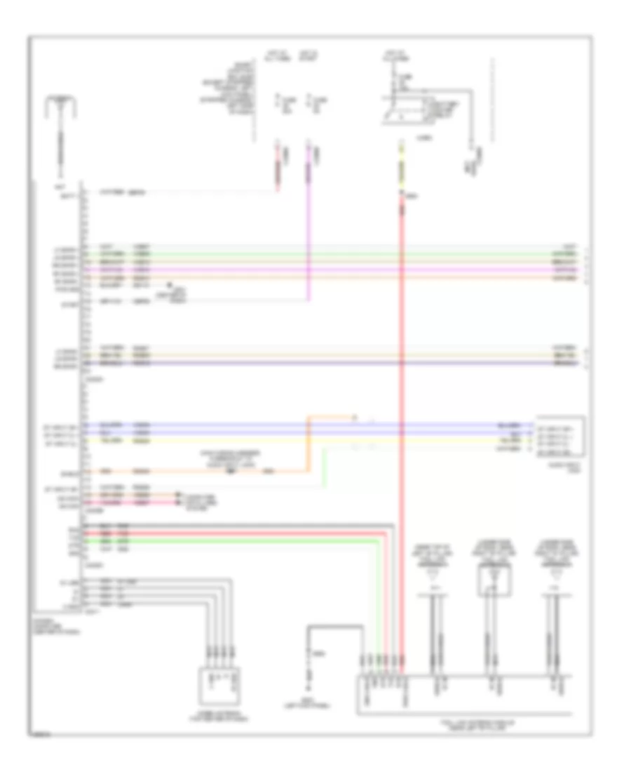
In Dash Computer Wiring Diagram (1 of 2) for Ford E-150 XL 2013
List of elements for In Dash Computer Wiring Diagram (1 of 2) for Ford E-150 XL 2013:
- (main wiring harness, in breakout to audio input jack) s241
- (near top of left "b" pillar) tool link antenna 1
- (under side of roof, near right "b" pillar) tool link antenna 2
- (under side of roof, near right "d" pillar) tool link antenna 3
- 5v usb
- Ant
- Antenna
- Audio input jack
- Batt +
- Battery saver relay
- C gnd
- C2280a
- C2280b
- C2280d
- C2408a
- C2408b
- C2408c
- C2411
- Cbp28
- Cgnd
- Coax cable
- Computer data lines system
- Dme45
- Dtr
- Fuse 10a
- Fuse 20a
- Fuse 5a
- G201 (center of dash)
- G203 (left kick panel)
- Gd115
- Gnd
- Gnd cable
- Hot at all times
- Hot in start
- In-dash computer (center of dash)
- Lf spkr +
- Lf spkr -
- Lr spkr +
- Lr spkr -
- Micro
- Modem antenna (top center of dash)
- Ms can+
- Ms can-
- Nca
- Pwr cable
- Pwr gnd
- Red
- Rf in
- Rf spkr +
- Rf spkr -
- Rme07
- Rme09
- Rme10
- Rme12
- Rme45
- Rme46
- Rr spkr +
- Rr spkr -
- Rxd
- S905
- S906
- Sbp39
- Shield
- Smart junction box (sjb) (except stripped chassis: left kick panel) (stripped chassis: left side of dash)
- St input 2l +
- St input 2l -
- St input 2r +
- St input 2r -
- Start
- Tool link antenna module (near left "b" pillar)
- Txd
- Used) (not
- Vdb06
- Vdb07
- Vme07
- Vme09
- Vme10
- Vme12
- Vme45
- Vme46
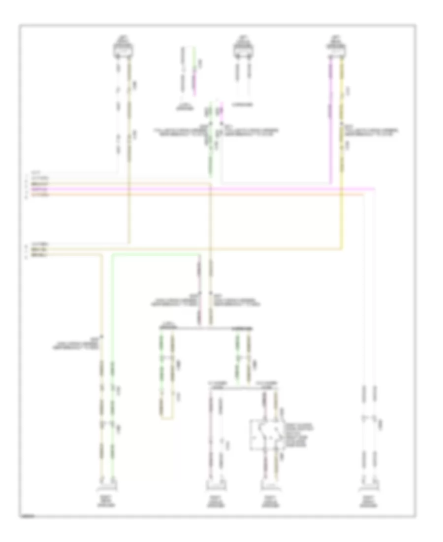
In Dash Computer Wiring Diagram (2 of 2) for Ford E-150 XL 2013
List of elements for In Dash Computer Wiring Diagram (2 of 2) for Ford E-150 XL 2013:
- 2 or 4 speaker
- 6 speaker
- C210
- C268
- C3007
- C3049
- C314
- C316
- C3235
- C406
- C411
- C807
- Left front speaker
- Left middle speaker
- Left rear speaker
- Right front speaker
- Right middle speaker
- Right rear speaker
- Right sliding door contact switch (right side of sliding side door)
- S207 (main wiring harness, near breakout to g200)
- S208 (main wiring harness, near breakout to g200)
- S209 (main wiring harness, near breakout to g200)
- S310 (taillights wiring harness, near breakout to c3135)
- S311 (taillights wiring harness, near breakout to c3135)
- W/ hinged door
- W/o hinged door
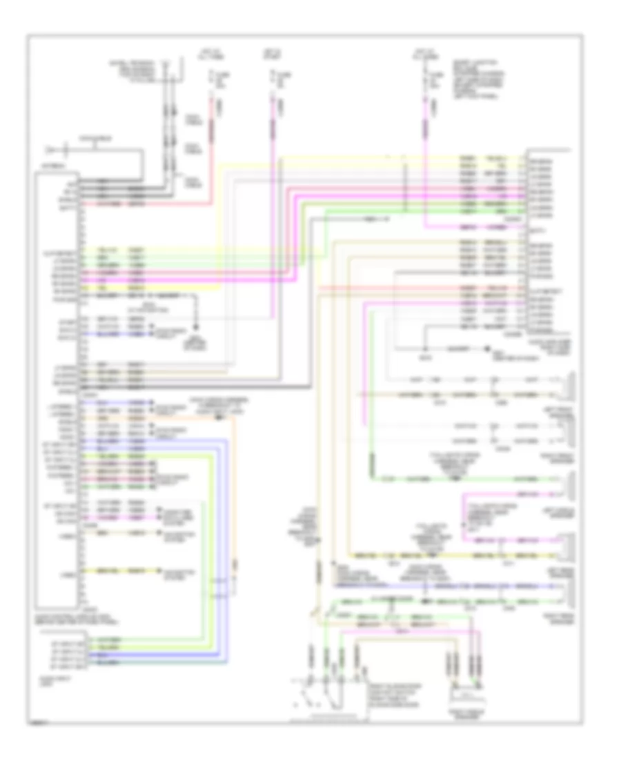
Navigation Wiring Diagram for Ford E-150 XL 2013
List of elements for Navigation Wiring Diagram for Ford E-150 XL 2013:
- (main wiring harness, in breakout to audio input jack) s241
- (main wiring harness, near breakout to g200)
- (main wiring harness, near breakout to g200) s207
- (right side of sliding side door)
- (taillights wiring harness, near breakout to c3135)
- (taillights wiring harness, near breakout to c3135) s311
- Ant
- Antenna
- Audio amplifier (right side of dash)
- Audio control module (acm) (behind center of dash panel)
- Audio input jack
- Batt+
- C210
- C2280a
- C2280b
- C2385a
- C2385b
- C240a
- C240b
- C240c
- C268
- C3007
- C3049
- C314
- C3235
- C406
- C411
- C807
- Cbp28
- Clip detect
- Cme27
- Coax cable
- Computer data lines system
- Dme17
- Dme43
- Dme45
- Fuse 20a
- Fuse 5a
- G201 (center of dash)
- Gd115
- Hot at all times
- Hot in start
- L stereo +
- L stereo -
- Left front speaker
- Left middle speaker
- Left rear speaker
- Lf spkr+
- Lf spkr-
- Lr spkr+
- Lr spkr-
- Mic +
- Mic -
- Mono +
- Mono -
- Ms can+
- Ms can-
- Navigation system
- Nca
- Pwr gnd
- R stereo +
- R stereo -
- Rf in
- Rf spkr+
- Rf spkr-
- Right front speaker
- Right middle speaker
- Right rear speaker
- Right sliding door contact switch
- Rme07
- Rme09
- Rme10
- Rme12
- Rme17
- Rme18
- Rme19
- Rme45
- Rme46
- Rme52
- Rme53
- Rme54
- Rme60
- Rme61
- Rmm23
- Rmn14
- Rr spkr+
- Rr spkr-
- S208 (main wiring harness, near breakout to g200)
- S209
- S216
- S216 (w/ navigation)
- S309
- Satellite radio/ gps antenna (top of right "a" pillar)
- Sbp39
- Sbp40
- Shield
- Smart junction box (sjb) (stripped chassis: left side of dash) (except stripped chassis: left kick panel)
- St input 2l+
- St input 2l-
- St input 2r+
- St input 2r-
- Start
- Swc 2+
- Swc 2-
- Sync radio circuit
- Vdb06
- Vdb07
- Video+
- Video-
- Vme07
- Vme09
- Vme10
- Vme12
- Vme17
- Vme18
- Vme19
- Vme43
- Vme45
- Vme46
- Vme52
- Vme53
- Vme54
- Vme60
- Vme61
- Vmm23
- Vmn14
- W/ hinged door
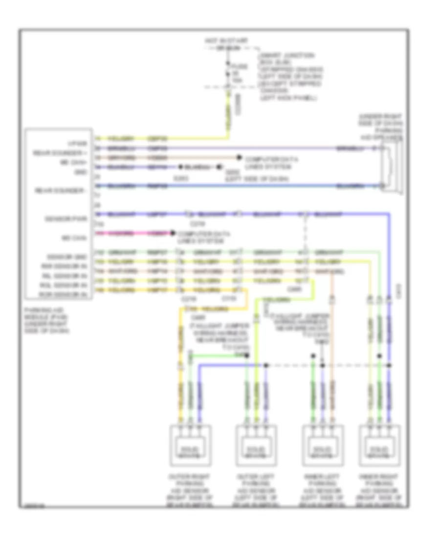
Parking Assistant Wiring Diagram for Ford E-150 XL 2013
List of elements for Parking Assistant Wiring Diagram for Ford E-150 XL 2013:
- (taillight jumper wiring harness, near breakout to c410) s402
- (taillight jumper wiring harness, near breakout to c410) s408
- (under right side of dash) parking aid speaker
- C110
- C219
- C2280b
- C410
- C495
- Cbp35
- Cmp09
- Computer data lines system
- Fuse 10a
- G202 (left side of dash)
- Gd114
- Gnd
- Hot in start or run
- Inner left parking aid sensor (left side of rear bumper)
- Inner right parking aid sensor (right side of rear bumper)
- Lmp07
- Ms can+
- Ms can-
- Outer left parking aid sensor (left side of rear bumper)
- Outer right parking aid sensor (right side of rear bumper)
- Parking aid module (pam) (under right side of dash)
- Rear sounder +
- Rear sounder -
- Ril sensor in
- Rir sensor in
- Rmp07
- Rmp09
- Rol sensor in
- Ror sensor in
- S263
- Sensor gnd
- Sensor pwr
- Smart junction box (sjb) (stripped chassis: left side of dash) (except stripped chassis: left kick panel)
- Solid state
- Vdb06
- Vdb07
- Vmp14
- Vmp15
- Vmp16
- Vmp17
- Vpwr
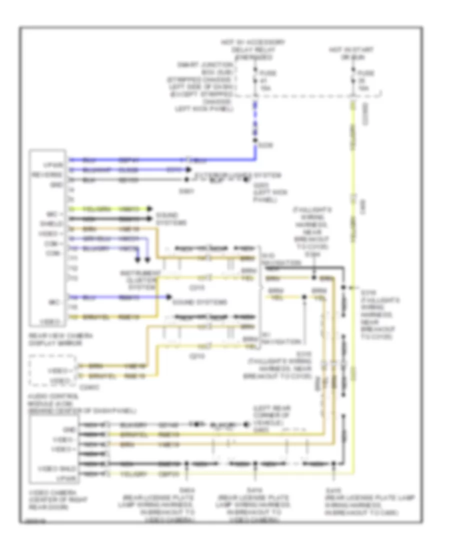
Rear Camera Wiring Diagram for Ford E-150 XL 2013
List of elements for Rear Camera Wiring Diagram for Ford E-150 XL 2013:
- (left rear corner of vehicle) g403
- (rear license plate lamp wiring harness, in breakout to c406)
- (taillights wiring harness, near breakout to c3135) s314
- Audio control module (acm) (behind center of dash panel)
- C210
- C2280d
- C240c
- C315
- C406
- C431
- Cbp35
- Cbp41
- Cls28
- Com +
- Com -
- Dme19
- Dmm13
- Exterior lights system
- Fuse 10a
- Fuse 15a
- G203 (left kick panel)
- Gd133
- Gd149
- Gnd
- Hot in start or run
- Hot w/ accessory delay relay energized
- Instrument cluster system
- Mic +
- Mic -
- Nca
- Rear view camera display mirror
- Reverse
- Rme19
- Rmm13
- S236
- S316 (taillights wiring harness, near breakout to c3135)
- S404 (rear license plate lamp wiring harness, in breakout to video camera)
- S414 (rear license plate lamp wiring harness, in breakout to video camera)
- S415
- S901
- Shield
- Smart junction box (sjb) (stripped chassis: left side of dash) (except stripped chassis: left kick panel)
- Sound systems
- Video +
- Video -
- Video camera (center of right rear door)
- Video shld
- Vmc30
- Vmc31
- Vme19
- Vmm13
- Vpwr
- W/o navigation nca

 Čeština
 Dansk
Dansk Deutsch
 Ελληνικά
 English
 English
 Español
 Suomi
Suomi Français
 Français
 עברית
עברית Hrvatski
 Magyar
 日本語
日本語 한국어
한국어 Nederlands
 Polski
 Português
 Português
 Română
 Русский
 Slovenčina
 Slovenščina
 Svenska
 Türkçe
 中文 (中国)