NAVIGATION
Blind Spot Information System Wiring Diagram for Ford Edge Sport 2014
 https://portal-diagnostov.com/license.html
Automotive Electricians Portal FZCO
Automotive Electricians Portal FZCO
https://portal-diagnostov.com/license.html
https://portal-diagnostov.com/license.html
Automotive Electricians Portal FZCO
Automotive Electricians Portal FZCO
List of elements for Blind Spot Information System Wiring Diagram for Ford Edge Sport 2014:
- (behind left side corner of rear bumper) left side obstacle detection control module (sod-l)
- (left "d" pillar) g400
- Address
- Alert
- Body control module (bcm) (left kick panel)
- C2280d
- C510
- C610
- Cbp34
- Computer data lines system
- Crb02
- Crb04
- Fuse 10a
- G201 (left kick panel)
- G202 (right kick panel)
- G404 (right "d" pillar)
- Gd149
- Gd151
- Gnd
- Hot in run or start
- Isp-r
- Left exterior mirror blind spot (blis)/ cross traffic alert (cta) led
- Left side exterior rear view mirror
- Ms can+
- Ms can-
- Nca
- Right exterior mirror blind spot (blis)/ cross traffic alert (cta) led
- Right side exterior rear view mirror
- Right side obstacle detection control module (sod-r)
- S308
- S402
- S408
- S502
- S604
- Vdb06
- Vdb07
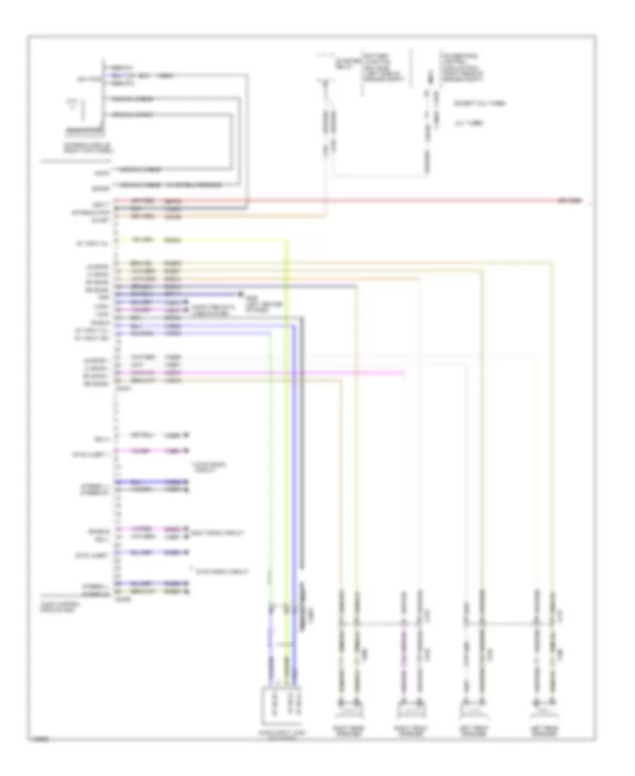
Navigation Wiring Diagram, with Premium (1 of 2) for Ford Edge Sport 2014
List of elements for Navigation Wiring Diagram, with Premium (1 of 2) for Ford Edge Sport 2014:
- (w/ satellite radio)
- 2.0l turbo
- Am/fm
- Ant pwr
- Antenna module (right kick panel)
- Antenna pwr
- Audio control module (acm)
- Audio input jack (w/o sync)
- Battery junction box (bjb) (left side of engine compt)
- C1381b
- C175b
- C213
- C215
- C219
- C240a
- C240b
- C3053
- C510
- C610
- C700
- C800
- Cdc26
- Coaxial cable
- Computer data lines system
- Dme45
- Enable
- Except 2.0l turbo
- G206 (left center of dash)
- Gd114
- Gnd
- I can+
- I can-
- Left front speaker
- Left rear speaker
- Lf spkr +
- Lf spkr-
- Lr spkr +
- Lr spkr-
- Nca
- Powertrain control module (pcm) (right rear of engine compt)
- Rf spkr +
- Rf spkr-
- Right front speaker
- Right rear speaker
- Rme07
- Rme09
- Rme10
- Rme12
- Rme45
- Rme52
- Rme53
- Rme80
- Rr spkr+
- Rr spkr-
- Sbp29
- Sdars
- Sdl-h
- Sdl-l
- Shield
- Smcs
- Sme23
- Solid state
- Sony radio circuit
- St in 2l +
- St in 2l -
- St in 2r +
- St input 2l+
- St input 2l-
- St input 2r+
- Start
- Starter relay
- Stereo l+
- Stereo l-
- Stereo r+
- Stereo r-
- Sync alert +
- Sync alert-
- Sync radio circuit
- Vbatt
- Vdb13
- Vdb14
- Vme07
- Vme09
- Vme10
- Vme12
- Vme43
- Vme45
- Vme46
- Vme52
- Vme53
- Vme80
- Vme90
- Vme91
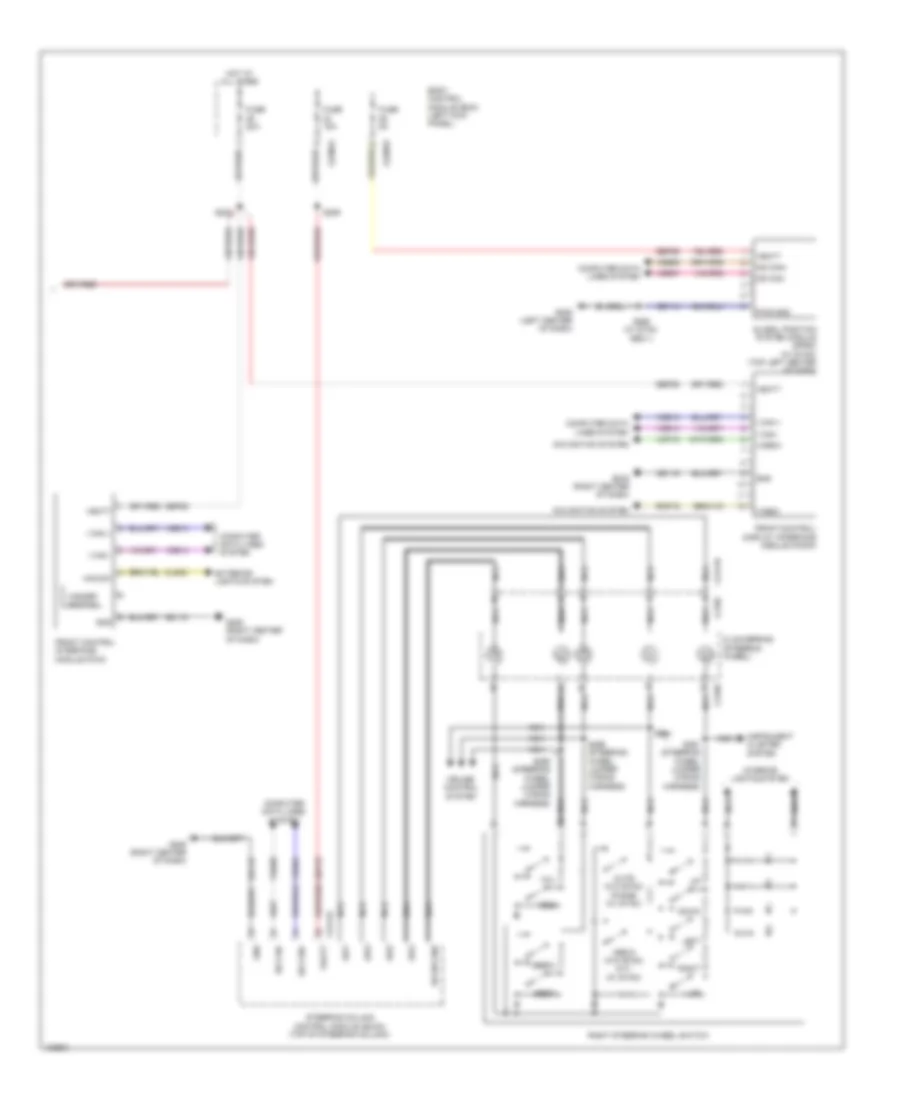
Navigation Wiring Diagram, with Premium (2 of 2) for Ford Edge Sport 2014
List of elements for Navigation Wiring Diagram, with Premium (2 of 2) for Ford Edge Sport 2014:
- A/d1
- A/d2
- A/d3
- A/d4
- Body control module (bcm) (left kick panel)
- C218b
- C218c
- C2280a
- C2280b
- C2414a
- C2414d
- Clockspring (steering wheel)
- Cls32
- Computer data lines system
- Cruise control system
- Down
- Exterior lights system
- Front control interface module (fcim)
- Front control/ display interface module (fcdim)
- Fuse 15a
- Fuse 20a
- Fuse 5a
- G205 (right center of dash)
- G206 (left center of dash)
- Gd114
- Gd115
- Global position system module (gpsm) (w/ sync) (top left center of dash)
- Gnd
- Haz sw
- Hazard switch
- Hot at all times
- Hs can+
- Hs can-
- I can +
- I can -
- Instrument cluster system
- Interior lights system
- Left
- Media (w/o sync) ptt (w/ sync)
- Ms can+
- Ms can-
- Mute (w/o sync) phone (w/ sync)
- Navigation system
- Nca
- Pwr gnd
- Rh sw gnd
- Right
- Right steering wheel switch
- Rmp19
- S222
- S229
- S268 (w/ sync gen 1)
- S291 (steering wheel jumper wiring harness)
- S294
- S295 (steering wheel jumper wiring harness)
- S296 (steering wheel jumper wiring harness)
- Sbp23
- Sbp26
- Sbp29
- Seek+
- Seek-
- Steering column control module (sccm) (top of steering column)
- Vbatt
- Vdb04
- Vdb05
- Vdb06
- Vdb07
- Vdb13
- Vdb14
- Video+
- Video-
- Vmp19
- Vol+
- Vol-
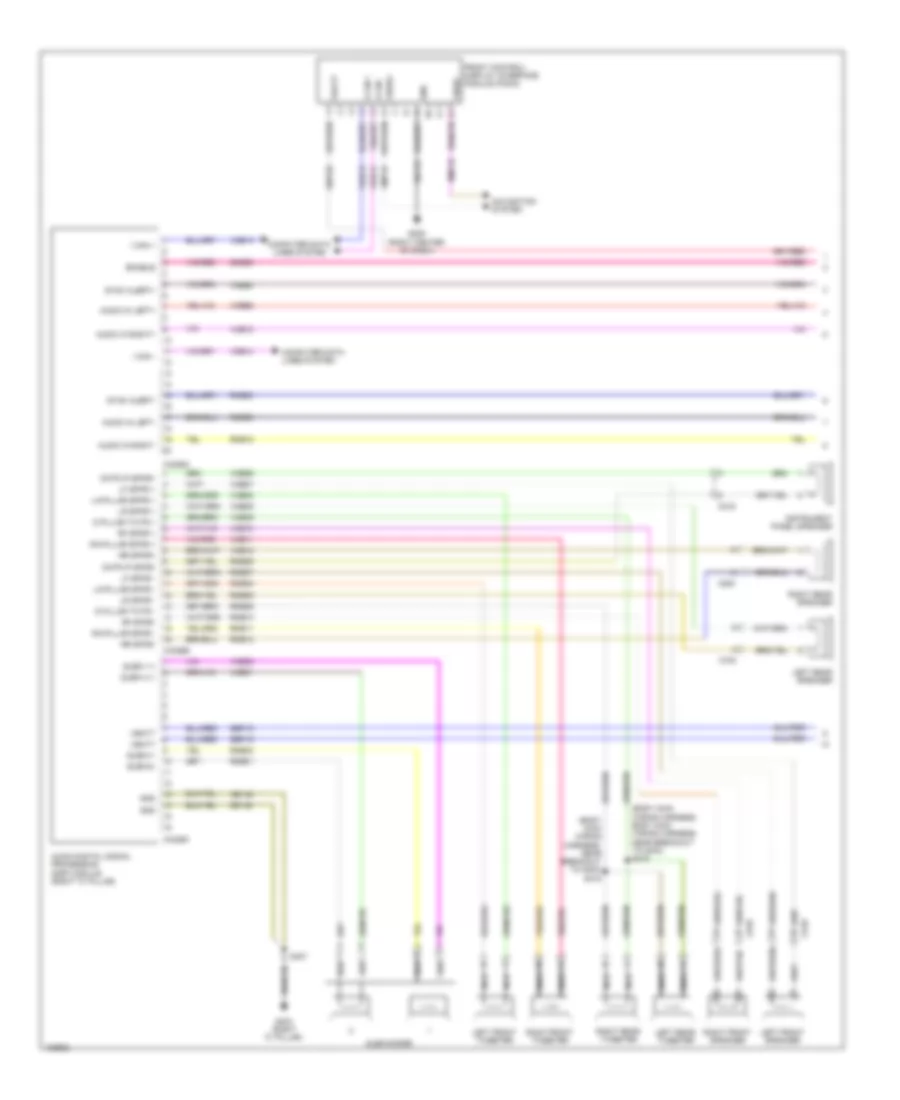
Navigation Wiring Diagram, with Sony (1 of 2) for Ford Edge Sport 2014
List of elements for Navigation Wiring Diagram, with Sony (1 of 2) for Ford Edge Sport 2014:
- (body main wiring harness, body main wiring harness, near breakout to g403) s416
- (body main wiring harness, near breakout to g403) s415
- Audio digital signal processing (dsp) module (right "c" pillar)
- Audio in left+
- Audio in left-
- Audio in right+
- Audio in right-
- C219
- C4326a
- C4326b
- C4326c
- C510
- C610
- C700
- C800
- Cntr ip spkr+
- Cntr ip spkr-
- Computer data lines system
- D pillar twtr +
- D pillar twtr -
- Enable
- Front control/ display interface module (fcdim)
- G205 (right center of dash)
- G403 (right "c" pillar)
- Gd115
- Gd148
- Gnd
- I can +
- I can -
- Instrument panel speaker
- La-pillar spkr +
- La-pillar spkr -
- Left front speaker
- Left front tweeter
- Left rear speaker
- Left rear tweeter
- Lf spkr +
- Lf spkr -
- Lr spkr +
- Lr spkr -
- Navigation system
- Nca
- Ra-pillar spkr +
- Ra-pillar spkr -
- Rf spkr +
- Rf spkr-
- Right front speaker
- Right front tweeter
- Right rear speaker
- Right rear tweeter
- Rme01
- Rme02
- Rme06
- Rme07
- Rme08
- Rme09
- Rme10
- Rme11
- Rme12
- Rme18
- Rme39
- Rme58
- Rme80
- Rmp19
- Rr spkr+
- Rr spkr-
- S407
- Sbp19
- Sbp29
- Sme23
- Subw 1+
- Subw 2 +
- Subw1-
- Subw2-
- Subwoofer
- Sync alert+
- Sync alert-
- Vbatt
- Vdb13
- Vdb14
- Video+
- Video-
- Vme01
- Vme02
- Vme06
- Vme07
- Vme08
- Vme09
- Vme10
- Vme11
- Vme12
- Vme18
- Vme39
- Vme58
- Vme80
- Vmp19
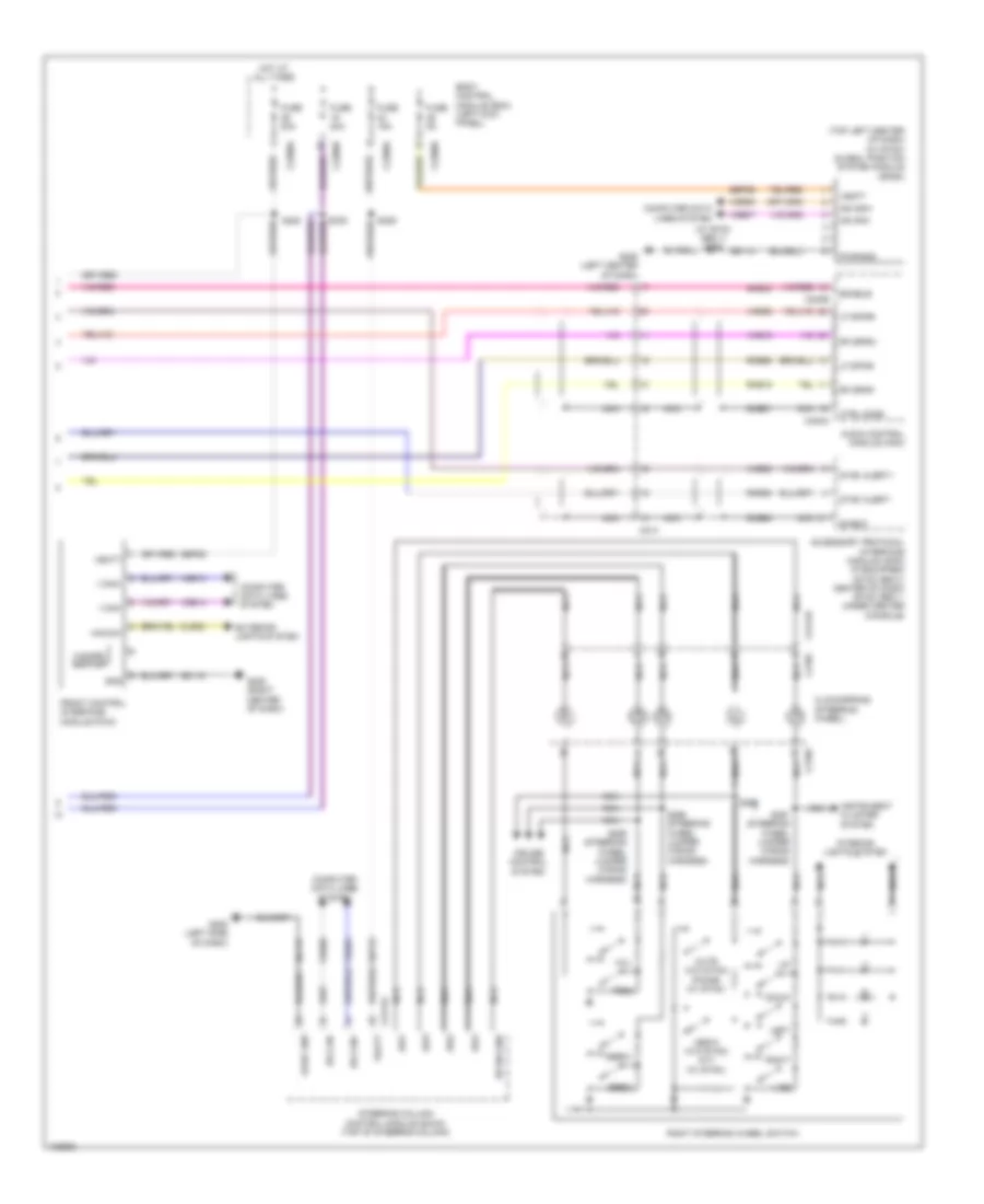
Navigation Wiring Diagram, with Sony (2 of 2) for Ford Edge Sport 2014
List of elements for Navigation Wiring Diagram, with Sony (2 of 2) for Ford Edge Sport 2014:
- (top left center of dash) (w/ sync) global position system module (gpsm)
- (w/ sync gen 1) s268
- A/d1
- A/d2
- A/d3
- A/d4
- Accessory protocol interface module (apim) (if equipped) (sync gen 2: center of dash) (sync gen 1: under center console)
- Audio control module (acm)
- Body control module (bcm) (left kick panel)
- C214
- C218b
- C218c
- C2280a
- C2280b
- C2280d
- C240a
- C240b
- C2414a
- C2414d
- Clockspring (steering wheel)
- Cls32
- Computer data lines system
- Cruise control system
- Ctrl mode
- Dme51
- Dme80
- Down
- Enable
- Exterior lights system
- Front control interface module (fcim)
- Fuse 15a
- Fuse 20a
- Fuse 5a
- G205 (left side of dash)
- G205 (right center of dash)
- G206 (left center of dash)
- Gd114
- Gd115
- Gnd
- Haz sw
- Hazard switch
- Hot at all times
- Hs can+
- Hs can-
- I can+
- I can-
- Instrument cluster system
- Interior lights system
- Left
- Lf spkr+
- Lf spkr-
- Logic gnd
- Media (w/o sync) ptt (w/ sync)
- Ms can+
- Ms can-
- Mute (w/o sync) phone (w/ sync)
- Nca
- Pwr gnd
- Rf spkr+
- Rf spkr-
- Rh sw gnd
- Right
- Right steering wheel switch
- Rme18
- Rme58
- Rme80
- S229
- S291 (steering wheel jumper wiring harness)
- S294
- S295 (steering wheel jumper wiring harness)
- S296 (steering wheel jumper wiring harness)
- Sbp23
- Sbp26
- Sbp29
- Seek+
- Seek-
- Shield
- Sme23
- Steering column control module (sccm) (top of steering column)
- Sync alert+
- Sync alert-
- Vbatt
- Vdb04
- Vdb05
- Vdb06
- Vdb07
- Vdb13
- Vdb14
- Vme18
- Vme58
- Vme80
- Vol+
- Vol-
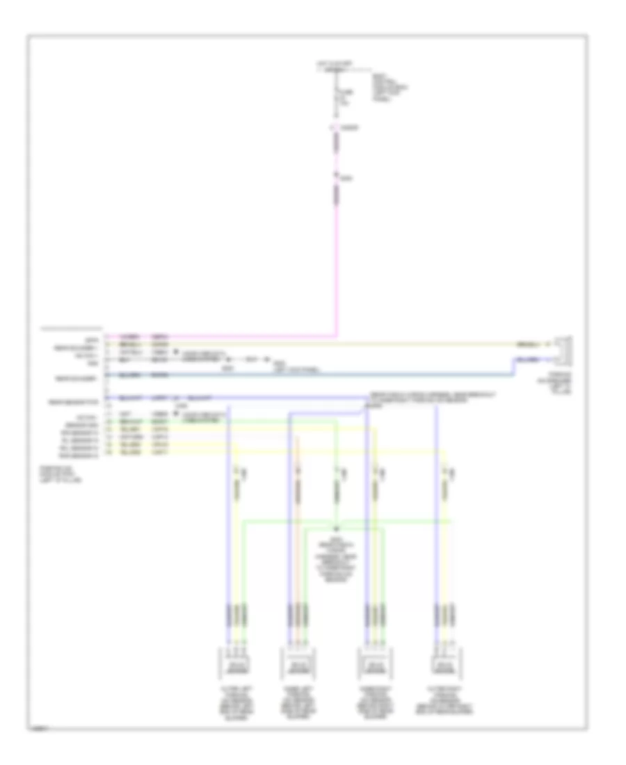
Parking Assistant Wiring Diagram for Ford Edge Sport 2014
List of elements for Parking Assistant Wiring Diagram for Ford Edge Sport 2014:
- (rear fascia wiring harness, near breakout to inner right parking aid sensor) s405
- Body control module (bcm) (left kick panel)
- C2280d
- C406
- Cbp34
- Cmp09
- Computer data lines system
- Fuse 10a
- G200 (left kick panel)
- Gd133
- Gnd
- Hot in start or run
- Hs can +
- Hs can -
- Inner left parking aid sensor (behind left side of rear bumper)
- Inner right parking aid sensor (behind right side of rear bumper)
- Isp-r
- Lmp07
- Outer left parking aid sensor (behind left end of rear bumper)
- Outer right parking aid sensor (behind outer right end of rear bumper)
- Parking aid module (pam) (left "d" pillar)
- Parking aid speaker (left "c" pillar)
- Rear sensor pwr
- Rear sounder +
- Rear sounder -
- Ril sensor in
- Rir sensor in
- Rmp07
- Rmp09
- Rol sensor in
- Ror sensor in
- S200
- S308
- S403 (rear fascia wiring harness, near breakout to inner right parking aid sensor)
- Sensor gnd
- Solid state
- Vdb04
- Vdb05
- Vmp14
- Vmp16
- Vmp17
- Vpm15
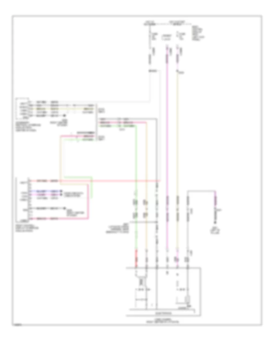
Rear Camera Wiring Diagram for Ford Edge Sport 2014
List of elements for Rear Camera Wiring Diagram for Ford Edge Sport 2014:
- Accessory protocol interface module (apim) (center of dash)
- Body control module (bcm) (left kick panel)
- C213
- C2280b
- C2280c
- C2280d
- C495
- C919
- Choke
- Computer data lines system
- Dmn19
- Electronics
- Front control/ display interface module (fcdim)
- Fuse 10a
- Fuse 20a
- G205 (right center of dash)
- G301 (left "b" pillar)
- Gd115
- Gnd
- Hot at all times
- Hot in start or run
- I can+
- I can-
- Lin
- Lin 03
- Micro
- Nca
- Red
- Rmp19
- S222
- S308
- S341
- S907 (liftgate wiring harness, near breakout to c919)
- Sbp29
- Shield
- Sync gen 1
- Sync gen 2
- Vbatt
- Vdb13
- Vdb14
- Video camera (right center of liftgate)
- Video+
- Video-
- Vmp19

 Čeština
 Dansk
Dansk Deutsch
 Ελληνικά
 English
 English
 Español
 Suomi
Suomi Français
 Français
 עברית
עברית Hrvatski
 Magyar
 日本語
日本語 한국어
한국어 Nederlands
 Polski
 Português
 Português
 Română
 Русский
 Slovenčina
 Slovenščina
 Svenska
 Türkçe
 中文 (中国)