POWER DISTRIBUTION
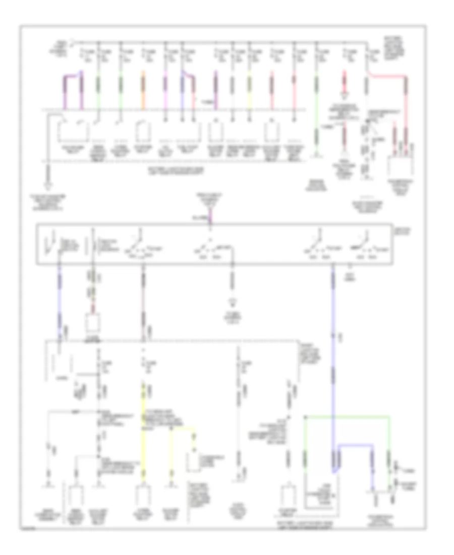
Power Distribution Wiring Diagram (1 of 4) for Ford Flex SE 2011
 https://portal-diagnostov.com/license.html
Automotive Electricians Portal FZCO
Automotive Electricians Portal FZCO
https://portal-diagnostov.com/license.html
https://portal-diagnostov.com/license.html
Automotive Electricians Portal FZCO
Automotive Electricians Portal FZCO
List of elements for Power Distribution Wiring Diagram (1 of 4) for Ford Flex SE 2011:
- (in breakout to subwoofer) s307
- (left side of engine compt) battery junction box (bjb)
- (near breakout to c3050) s326
- (not used)
- (to headlamp junction near breakout to auxiliary relay box) s194
- (to headlamp junction near breakout to left front of engine compt, on transaxle) s181
- (turbo: near breakout to coil on plug 4) (except turbo: to headlamp junction near breakout to left front of engine compt, on transaxle) s157
- 3rd rao seat enable (fet)
- Adjustable pedal switch
- Anti-lock brake system (abs) module
- Audio amplifier
- Battery
- Battery charge relay
- Battery junction box (bjb) (left side of engine compt)
- Brake pedal position (bpp) switch
- Bsi (fet)
- C1045
- C1284a
- C1285a
- C145
- C1463b
- C210
- C211
- C2280d
- C2280g
- C3049
- C3050
- C312
- C3206
- C328
- C341a
- C341b
- C411
- C4174b
- C4208c
- C510
- Driver seat module (dsm)
- Driver side front power window motor
- Driver side front seat control switch
- Exterior rear view mirror switch
- Front console power point
- Front passenger side seat control switch
- Fuse 10a
- Fuse 15a
- Fuse 20a
- Fuse 30a
- Fuse 40a
- Fuse 5a
- Fuse 7.5a
- Fuse 80a
- G203 (center of dash)
- G300 (right "d" pillar)
- Generator
- Instru- ment panel power point
- Interior lighting (fet)
- Key pad illum (fet)
- Keypad switch assembly
- Left headlamp assembly
- Liftgate/ trunk module (ltm)
- Micro
- Power steering control module (pscm)
- Rear console power point
- Rear power point
- Red
- Right headlamp assembly
- Right low beam (fet)
- S182 (to headlamp junction near breakout to left front of engine compt, on transaxle)
- S183 red (to headlamp junction near breakout to auxiliary relay box)
- S383
- Smart junction box (sjb) (left side of dash)
- Starter motor
- To dc/ac inverter module (diagram 4 of 4)
- To fuse 11 (diagram 2 of 4)
- To fuse 6 (diagram 3 of 4)
- Trailer brake control (tbc) module
- Trailer tow left turn relay
- Trailer tow park lamp relay
- Trailer tow right turn relay
- W/ 6 way power seat
- W/ memory
- W/o 6 way power seat
- W/o memory
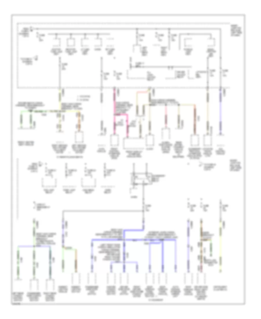
Power Distribution Wiring Diagram (2 of 4) for Ford Flex SE 2011
List of elements for Power Distribution Wiring Diagram (2 of 4) for Ford Flex SE 2011:
- (near breakout to c139) s150
- (not used)
- A/c clutch relay
- Acc
- Acc run
- Audio control module (acm)
- Auxiliary blower motor relay
- Battery junction box (bjb) (left side of engine compt)
- Blower motor relay
- C1381b
- C175b
- C210
- C211
- C2280a
- C2280b
- C2280d
- C2280e
- C240a
- C312
- C315
- C983
- Engine cooling fan motor
- Evap canister vent control solenoid
- Except turbo
- Floor shifter
- From fuse 27 (diagram 4 of 4)
- From fuse 7 (diagram 1 of 4)
- From pcm power relay (diagram 2 of 4)
- Fuel pump relay
- Fuse 10a
- Fuse 15a
- Fuse 20a
- Fuse 25a
- Fuse 30a
- Fuse 40a
- Fuse 5a
- Fuse 7.5a
- Fuse 80a
- Ignition lock solenoid
- Ignition switch
- Key in ignition switch
- Micro
- Off
- One touch integrated start diode
- Pcm power relay
- Powertrain control module (pcm)
- Rear window defrost relay
- Rear wiper motor assembly
- Rear wiper relay
- Red
- Reversing lamps relay
- Run
- S116 (to headlamp junction near breakout to battery junction box (bjb))
- S193 (near breakout to anti-lock brake system module)
- S345 (near breakout to left kick panel)
- Smart junction box (sjb) (left side of dash)
- Smrc
- Start
- Starter relay
- Third row power seat relay
- To console refrigeration relay (diagram 4 of 4)
- To evap canister vent control solenoid (diagram 2 of 4)
- To s221 (diagram 4 of 4)
- Turbo
- Used) (not
- Windshield wiper motor
- Wiper run/park relay
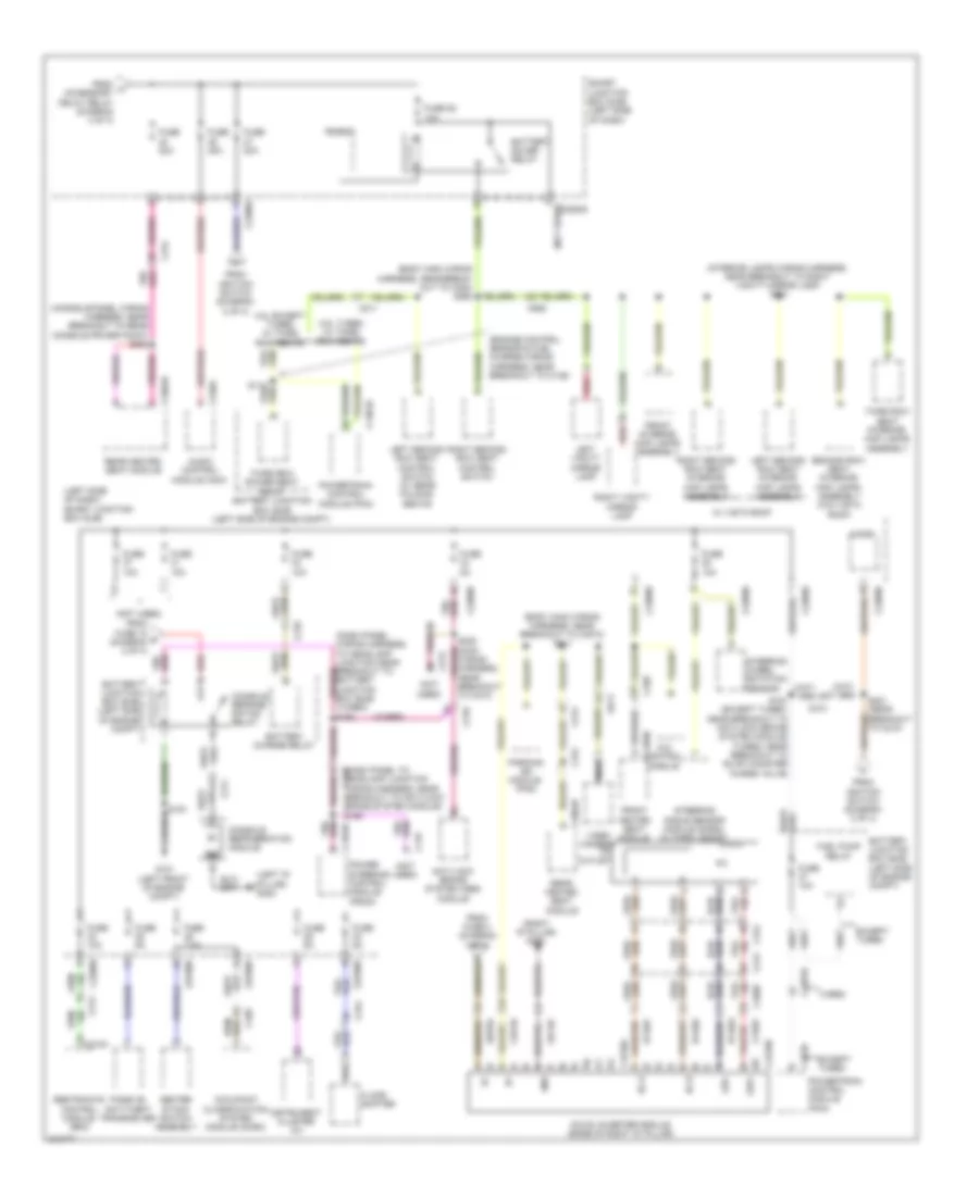
Power Distribution Wiring Diagram (3 of 4) for Ford Flex SE 2011
List of elements for Power Distribution Wiring Diagram (3 of 4) for Ford Flex SE 2011:
- (body main wiring harness, near breakout to c354) s361
- (body main wiring harness, near breakout to left "a" pillar speaker) s318
- (body main wiring harness, near breakout to restraints control module) s347
- (interior lamps wiring harness, near breakout to right vanity mirror lamp) s906
- (left front door window regulator wiring harness, near breakout to driver side front power window motor) s503
- (main wiring harness, near breakout to c210) s240
- (main wiring harness, near breakout to instrument cluster) s230
- (near breakout to c210) s220
- (power seats wiring harness, near breakout to c3265a) s355
- 4x4 control module
- Accessory delay relay
- Accessory protocol interface module (fpim) (w/ sync)
- All lock/ unlock relay
- Ambient lighting module
- Ambient lighting switch
- Auto dimming interior mirror unit
- Back- lighting led (fet)
- C213
- C2280a
- C2280b
- C2280d
- C228a
- C2949a
- C3050
- C312
- C3133
- C3134
- C3249
- C328
- C339
- C340
- C359b
- C4174b
- C510
- C610
- C925
- Circuit breaker 47 30a
- Clock
- Data link connector (dlc)
- Driver side door lock switch
- Driver side front seat control switch (w/ memory seats)
- Driver unlock relay
- Fog lamp relay
- From fuse 18 (diagram 3 of 4)
- From fuse 8 (diagram 1 of 4)
- Front control interface module (fcim)
- Front display interface module (fdim)
- Front driver side power window motor
- Front heated seat module
- Fuse 10a
- Fuse 15a
- Fuse 17 20a
- Fuse 20a
- Fuse 21 15a
- Fuse 22 15a
- Fuse 23 15a
- Fuse 24 20a
- Fuse 25a
- Global positioning system module (gpsm)
- High beam relay
- Horn relay
- Hvac module
- Instrument cluster (ic)
- Left low beam (fet)
- Left rear window control switch
- Left second row power fold seat motor
- Lf turn lamp (fet)
- Liftgate rel (fet)
- Liftgate/ trunk module (ltm)
- Lr stop/ turn lamp (fet)
- Master window control switch
- Micro
- Park lamp relay
- Passenger side door lock switch
- Passenger side window control switch
- Puddle lamp (fet)
- Rear enter- tainment module (retm) (if equipped)
- Rf turn lamp (fet)
- Right low beam (fet)
- Right rear window control switch
- Right second row power fold seat motor
- Roof opening panel control switch
- Roof opening panel module
- Rr stop/ turn lamp (fet)
- Smart junction box (sjb) (left side of dash)
- To fuse 21 (diagram 3 of 4)
- To fuse 40 (diagram 4 of 4)
- W/ moonroof
- W/ navi- gation
- W/ rear folding seats
- W/ sync
- W/o navi- gation
- W/o sync
Power Distribution Wiring Diagram (4 of 4) for Ford Flex SE 2011
List of elements for Power Distribution Wiring Diagram (4 of 4) for Ford Flex SE 2011:
- (body main wiring harness, near break- out to c354) s360
- (body main wiring harness, near breakout to c3073) s311
- (console panel wiring harness, near breakout to rear console power point) s382
- (dash panel to c145 headlamp junction wiring harness, near breakout to anti-lock brake system module) s155
- (engine control sensor & fuel charge wiring harness, near breakout to c139)
- (interior lamps wiring harness, near breakout to right vanity mirror lamp) s901
- (left "d" pillar) g302
- (left side of dash) smart junction box (sjb)
- (not used)
- (right "d" pillar) g300
- 3.5l except turbo w/ third row seats
- 3.5l turbo w/ third row seats
- 4x4 control module
- Ac outlet
- Ac-a
- Ac-b
- Anti-lock brake system (abs) module
- Audio control module (acm)
- Battery charge relay
- Battery junction box (bjb) (left side of engine compt)
- Battery saver relay
- C1381b
- C145
- C1463a
- C175b
- C210
- C211
- C212
- C213
- C2280a
- C2280b
- C2280d
- C2280e
- C240a
- C310a
- C312
- C3206
- C328
- C3304b
- C359b
- C4210a
- C4210b
- C913
- C925
- Cbp35
- Center stack switch assembly
- Console refrige- ration relay
- Console refrigeration module
- Dc/ac inverter module (base of right "d" pillar)
- Except turbo
- Floor shifter
- From fuse 15 d (diagram 2 of 4)
- From fuse 4 (diagram 1 of 4)
- From h accessory delay relay (diagram 3 of 4)
- From ignition switch (diagram 2 of 4)
- Front heated seat module
- Front interior/ map lamps assembly
- Fuel pump relay
- Fuse 10a
- Fuse 20a
- Fuse 25 10a
- Fuse 5a
- Fuse 7.5a
- G101 (left front of engine compt)
- Gd148
- Gnd
- Hya01
- Hya02
- Instrument cluster (ic)
- Led+
- Led-
- Left second row seat control switch (w/ rear folding seats)
- Left second row seat interior/ map lamps assembly
- Left vanity mirror lamp
- Lya03
- Micro
- Nca
- Occupant classification system module (ocsm)
- Parking aid module (pam)
- Passive anti-theft transceiver
- Power steering control module (pscm)
- Powertrain control module (pcm)
- Rear heated seat module
- Red
- Restraints control module (rcm)
- Right second row seat control switch
- Right second row seat interior/ map lamps assembly
- Right vanity mirror lamp
- Rya03
- S161 (except turbo: near breakout to anti-lock brake system module) (turbo: near breakout to evap canister purge valve)
- S191
- S221 (near breakout to c210)
- Sbp04
- Second row seat interior/ map lamps assembly (w/o vista roof)
- Smart junction box (sjb) (left side of dash)
- Steering angle sensor module (sasm) (w/ park assist)
- Steering wheel rotation sensor
- Third row power seat relay battery junction box (bjb) (left side of engine compt)
- Third row seat interior/ map lamps assembly
- Turbo
- Video camera
- W/ vista roof

 Čeština
 Dansk
Dansk Deutsch
 Ελληνικά
 English
 English
 Español
 Suomi
Suomi Français
 Français
 עברית
עברית Hrvatski
 Magyar
 日本語
日本語 한국어
한국어 Nederlands
 Polski
 Português
 Português
 Română
 Русский
 Slovenčina
 Slovenščina
 Svenska
 Türkçe
 中文 (中国)