SUPPLEMENTAL RESTRAINTS
Supplemental Restraints Wiring Diagram (1 of 2) for Ford Taurus LX 2004
 https://portal-diagnostov.com/license.html
Automotive Electricians Portal FZCO
Automotive Electricians Portal FZCO
https://portal-diagnostov.com/license.html
https://portal-diagnostov.com/license.html
Automotive Electricians Portal FZCO
Automotive Electricians Portal FZCO
List of elements for Supplemental Restraints Wiring Diagram (1 of 2) for Ford Taurus LX 2004:
- (at base of left "a" pillar) g202
- (right rear side of engine compt) s227
- (right rear side of engine compt) s331
- Air bag deactivation warning
- Air bag indicator
- C2280b
- C2280c
- C310a
- C310b
- Can+
- Can-
- Data link connector (dlc) (mounted on dash, below steering column)
- Disabled ind
- Fuse 10a
- G202 (at base of left "a" pillar)
- Ground
- Hot in run or start
- Ind ctrl
- Instrument cluster
- Integrated control panel
- Iso
- Left safety belt assembly
- Left side impact sensor
- Microprosser
- Nca
- Pin shorting bars engaged when module connector is disconnected from harness. shorting bars are connected between following pins: 1-2, 3-4, 5-6, 13-14 & 16-19 c310a 3-4 & 5-6 c310b
- Red
- Restraints control module (under center of dash)
- Right safety belt assembly (under passenger seat)
- Right side impact sensor
- S209 (left side of dash, behind instrument cluster)
- S227 (right rear side of engine compt)
- S250 (left end of dash)
- Safety belt buckle pretensioner
- Safety belt buckle switch
- Shorting bar
- Sig rtn
- Smart junction box (under left side of dash)
- Tone
- Twisted pair
- Vpwr
- Vref
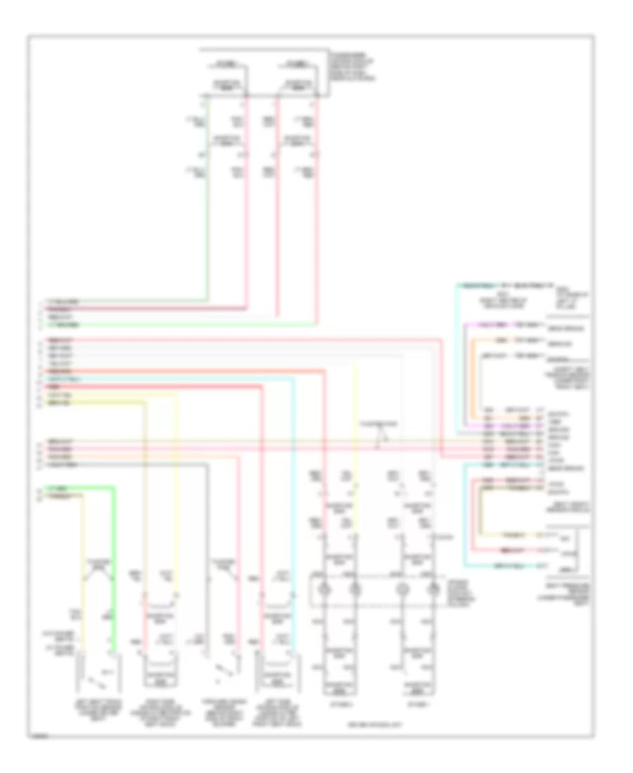
Supplemental Restraints Wiring Diagram (2 of 2) for Ford Taurus LX 2004
List of elements for Supplemental Restraints Wiring Diagram (2 of 2) for Ford Taurus LX 2004:
- (w/ power seats)
- (w/o power seats)
- Air bag sliding contact (steering column)
- C218a
- Can+
- Can-
- Driver air bag unit
- Forward crash sensor (behind right side of front bumper)
- G202 (at base of left "a" pillar)
- Gnd
- Ground
- Left seat track position sensor (under driver seat)
- Left side air bag module (inside outer portion of left front seat back)
- Nca
- Passenger's air bag module (behind right side of dash, near glove box)
- Red
- Right side air bag module (inside outer portion of right front seat back)
- S331 (right center of vehicle floor)
- Safety belt tension sensor (under right front seat)
- Seat pressure sensor (under passenger seat)
- Seat weight sensor module
- Sens ground
- Sens sig
- Shorting bar
- Sig
- Sig rtn
- Stage 1
- Stage 2
- Twisted pair
- Vpwr
- Vref

 Čeština
 Dansk
Dansk Deutsch
 Ελληνικά
 English
 English
 Español
 Suomi
Suomi Français
 Français
 עברית
עברית Hrvatski
 Magyar
 日本語
日本語 한국어
한국어 Nederlands
 Polski
 Português
 Português
 Română
 Русский
 Slovenčina
 Slovenščina
 Svenska
 Türkçe
 中文 (中国)