TRANSMISSION
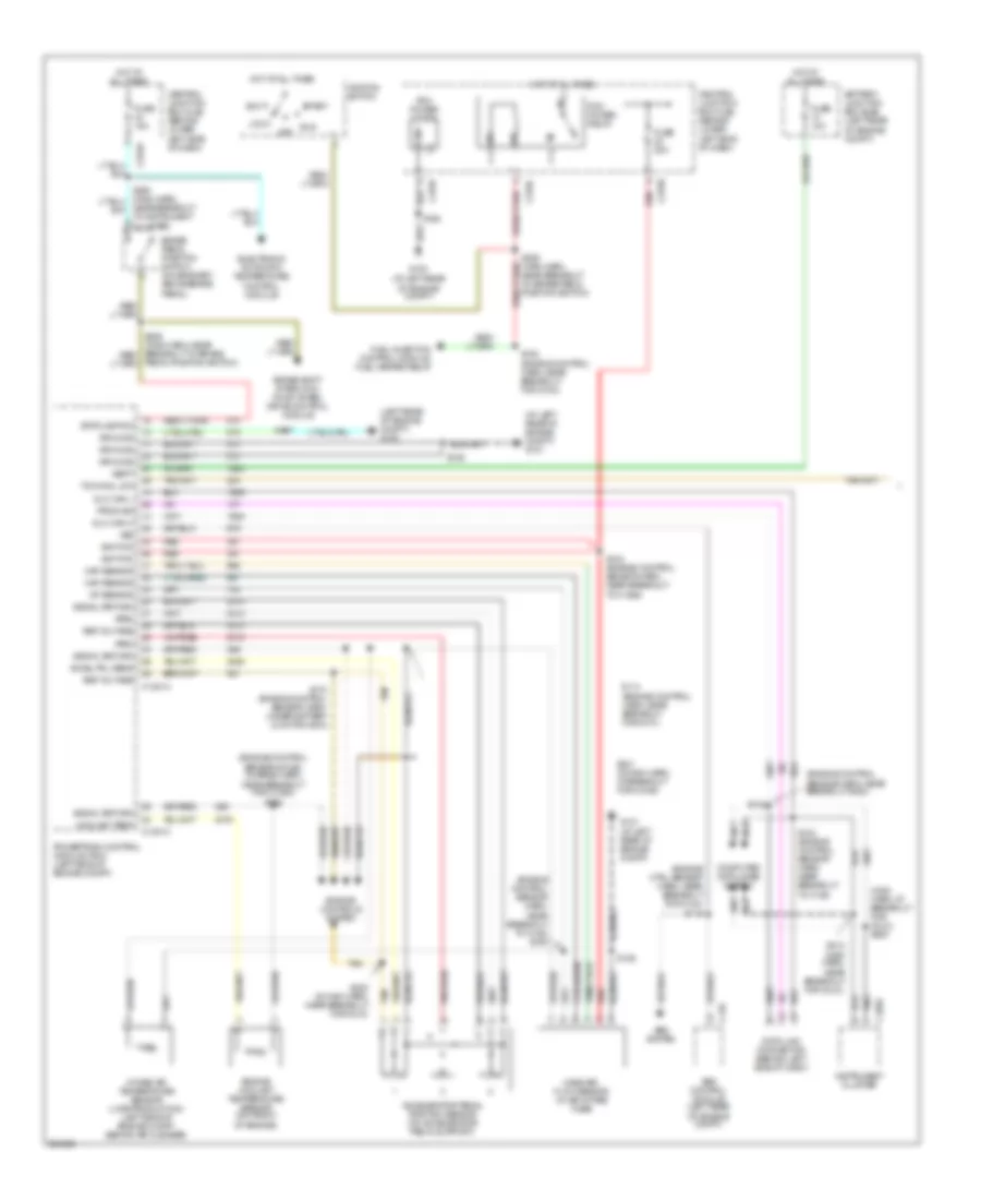
4WD Wiring Diagram for Ford F550 Super Duty 2005
 https://portal-diagnostov.com/license.html
Automotive Electricians Portal FZCO
Automotive Electricians Portal FZCO
https://portal-diagnostov.com/license.html
https://portal-diagnostov.com/license.html
Automotive Electricians Portal FZCO
Automotive Electricians Portal FZCO
List of elements for 4WD Wiring Diagram for Ford F550 Super Duty 2005:
- (engine control harn, near breakout for g100) s124
- (gasoline: left rear of engine compt) (diesel: left side of engine compt)
- (in back up lamp switch harn, near breakout to auxiliary relay box 3)
- (in main harn, near break- out to brake pedal position switch)
- (in main harn, near breakout for instrument cluster)
- (main harn, near breakout for instrument cluster) s254
- (main harn, near breakout for instrument cluster) s271
- (main harn, near breakout for restraints control module) s230
- (not used)
- 4wd hi
- 4wd hi ind
- 4wd lo
- 4wd lo ind
- 4wd sw
- 87a
- Abs control module
- Abs system
- Auxiliary relay box 3 (gasoline: left rear side of engine compt) (diesel: left side of engine compt)
- Battery
- Battery junction box (bjb) (left rear of engine compt)
- Bpp sw
- Brake pedal position switch (behind left side of dash, above brake pedal)
- C135
- C1381a neut sw sen
- C175b
- C220b
- C270a
- C270h
- C281a
- C281b
- C350a
- C350b
- Central junction box (cjb) (lower left side of dash)
- Computer data lines system
- Data link connector (behind left side of dash)
- Eatc module
- Electronic shift-on-the-fly (esof) solenoid (right side of engine compt)
- Enc gnd rtn
- Esof sol
- Esof solenoid, vacuum pump motor, drl relay
- Exterior lights system
- Four-wheel drive control module (behind right side of dash)
- Four-wheel drive switch
- Fuse 10a
- Fuse 15a
- Fuse 30a
- G201 (behind left side of dash)
- G202 (behind left side of dash)
- G300 (at floor, in left front footwell)
- Gas diesel
- Ground
- Hi to lo
- Hot at all times
- Hot in run
- Hot in run or acc
- Hot in run or start
- Ign (st/run)
- Illum
- Instrument cluster
- Instrument cluster, electrochromatic inside mirror unit, compass sensor module, clutch pedal position switch
- Instrument cluster, windshield wiper motor, fuel tank selector switch
- Interior lights system
- Iso bus
- Lo to hi
- Mtr pos 2
- Mtr pos 3
- Mtr pos 4
- Mtr pos 5
- Neut sens
- Off
- Powertrain control module (diesel: left side of engine compt) (gas: left side of firewall)
- Red
- Ref volt
- S163
- S201
- S205
- S225 (main harn, near break- out for instrument cluster)
- S228 (main harn, near breakout for instrument cluster)
- S250
- S253 (main harn, at breakout for instrument cluster)
- S257
- S259
- S268
- Shift sol
- Transfer case assembly
- Transfer case high to low relay
- Transfer case low to high relay
- Vehicle security module
- Vpwr
- Vss
- Vss out
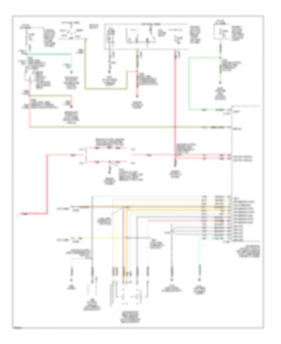
6.0L DIESEL
6.0L Diesel, A/T Wiring Diagram (1 of 2) for Ford F550 Super Duty 2005
List of elements for 6.0L Diesel, A/T Wiring Diagram (1 of 2) for Ford F550 Super Duty 2005:
- (at left rear of engine compt) g101
- (engine control sensor & fuel charge harn, near breakout for c1064) s192
- (engine control sensor harn,
- (engine control sensor harn, near breakout g300)
- (engine ctrl sensor harn, near breakout for c124) s115
- (left rear of engine compt) g100
- (main harn, at breakout for (dlc)) s220
- Abs control module (left rear of engine compt)
- Abs system
- Acc
- Accel pdl sens
- Accelerator pedal position sensor (on accelerator pedal support)
- Aps2
- Aps3
- Battery junction box (bjb) (left rear of engine compt)
- Brake pedal position switch (on bracket, above brake pedal)
- Brake shift interlock, four wheel drive control module
- C135
- C1381a
- C1381c
- C220a
- C270a
- C270c
- C270f
- C270h
- Central junction box (cjb) (behind lower left side of dash)
- Computer data lines system
- Coolant temp
- Data link connector (behind left side of dash)
- Dlc can h
- Dlc can l
- Electronic automatic temperature control module
- Engine controls system
- Engine coolant temperature sensor (on front of engine)
- Fuel injection control module, fuel heater relay
- Fuse 10a
- Fuse 15a
- Fuse 20a
- G100 (at left rear of engine compt)
- G101 (at left rear of engine compt)
- Ground
- Hot at all times
- Iat sensor
- Ignition
- Ignition switch
- Instrument cluster
- Intake air temperature sensor (late production) (left side of engine compt, behind air cleaner)
- Lock
- Maf sensor
- Mass air- flow sensor (in air intake tube)
- Near breakout to brake pedal position switch)
- Near breakout to c128) s150
- Near breakout to instrument cluster)
- Off
- Pcm power diode
- Pcm power relay
- Pedal position switch)
- Powertrain control module (pcm) (left side of engine compt)
- Prog sig
- Red
- Ref voltage
- Run
- S106
- S114 (engine control harn, near breakout for g101)
- S117
- S123 (engine control sensor harn, near breakout to c1298)
- S140
- S142 (engine control sensor harn, near breakout to c135)
- S162
- S170 (engine control sensor harn, under battery junction box)
- S182 (engine control harn, near breakout for g100)
- S213 (main harn, near breakout for (dlc))
- S221 (in main harn, at breakout for c2186)
- S223 (in main harn, near breakout for c218)
- Signal return
- Start
- Stoplamp sw
- Tan
- Tow/haul sw
- Vbatt
- Vss
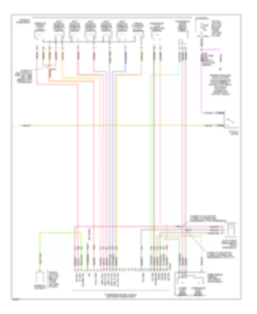
6.0L Diesel, A/T Wiring Diagram (2 of 2) for Ford F550 Super Duty 2005
List of elements for 6.0L Diesel, A/T Wiring Diagram (2 of 2) for Ford F550 Super Duty 2005:
- (in back-up lamp switch to rear lamp feed harn, near breakout for c1107)
- (in back-up light switch to rear light feed harn, near breakout for transmission)
- (not used)
- C1381b
- C270a
- Central junction box (cjb) (behind lower left side of dash)
- Fuse 15a
- Hot in run
- Intermediate shaft speed sensor
- Iss sig
- Nca
- Oss sig
- Output shaft speed sensor (top of transmission)
- Pc sol pwr
- Pc-a sol
- Powertrain control module (left side of engine compt)
- Pressure control (pc-a) solenoid
- Ref volt
- Rev lmp ctrl
- Reversing lamp relay
- S127
- S128
- S129
- S235 (main harn, near breakout to sunload sensor)
- Shift solenoid pressure control a (sspc-a)
- Shift solenoid pressure control b (sspc-b)
- Shift solenoid pressure control c (sspc-c)
- Shift solenoid pressure control d (sspc-d)
- Shift solenoid pressure control e (sspc-e)
- Sig trn
- Speed sensor assembly (left side of transmission)
- Sspc-a crl
- Sspc-b ctrl
- Sspc-c crl
- Sspc-d ctrl
- Sspc-e ctrl
- Tcc sol ctrl
- Temperature blend door actuator, function selector switch assembly, blower motor relay, electronic automatic temperature control module
- Tft sens sig
- Torqshift transmission
- Torque converter clutch solenoid
- Tow/haul switch
- Tr-p gnd
- Tr-p sig
- Transmission fluid temperature sensor
- Transmission range sensor assembly (tr-p)
- Tro
- Tss sig
- Turbine shaft speed sensor
6.8L
6.8L, A/T Wiring Diagram (1 of 2) for Ford F550 Super Duty 2005
List of elements for 6.8L, A/T Wiring Diagram (1 of 2) for Ford F550 Super Duty 2005:
- (back-up lamp switch to rear lamp feed harn, near breakout for c1385)
- (back-up light switch to rear light feed harn, near breakout for transmission)
- (main harn, at breakout for (dlc))
- (top of transmission) output shaft speed sensor
- Breakout for c135)
- C175a
- C175b
- C175c
- C220a
- Computer data lines system
- Cyl head temp
- Cylinder head temperature sensor (6.8l: on left cyl head) (5.4l: rear of block under intake)
- Data link connector (behind left side of dash)
- Electronic throttle control motor (on throttle body)
- Engine controls system
- Etc return
- Etc wot cntrl
- G102 (right rear of engine compt)
- Hs can +
- Hs can -
- Iat sensor
- Instrument cluster
- Intermediate shaft speed sensor
- Iss sensor
- Maf sensor
- Mass air flow (maf) sensor (left front of engine compt)
- Oss sensor
- Powertrain control module (on left side of firewall)
- Pressure control (pc-a) solenoid
- Prog sig
- Red
- Ref voltage
- S109 (engine control sensor harn, near breakout for c135)
- S127
- S128 (back-up light switch to rear light feed harn, near breakout for transmission)
- S129
- S132 (engine control sensor & fuel charge harn, near breakout for cop 7)
- S143
- S146
- S213 (main harn, near breakout to (dlc))
- S220
- Shift sol a
- Shift sol b
- Shift sol c
- Shift sol d
- Shift sol e
- Shift solenoid pressure control a (sspc-a)
- Shift solenoid pressure control b (sspc-b)
- Shift solenoid pressure control c (sspc-c)
- Shift solenoid pressure control d (sspc-d)
- Shift solenoid pressure control e (sspc-e)
- Signal return
- Speed sensor assembly (top left side of transmission)
- Tcc sol
- Tft sensor
- Throttle position sensor (top center of engine)
- Torqshift transmission
- Torque converter clutch solenoid
- Tps 2 sig
- Tps output
- Tps sig
- Tps sig return
- Transmission fluid temperature sensor
- Transmission range sensor assembly (tr-p)
- Trs sensor
- Tss sensor
- Turbine shaft speed sensor
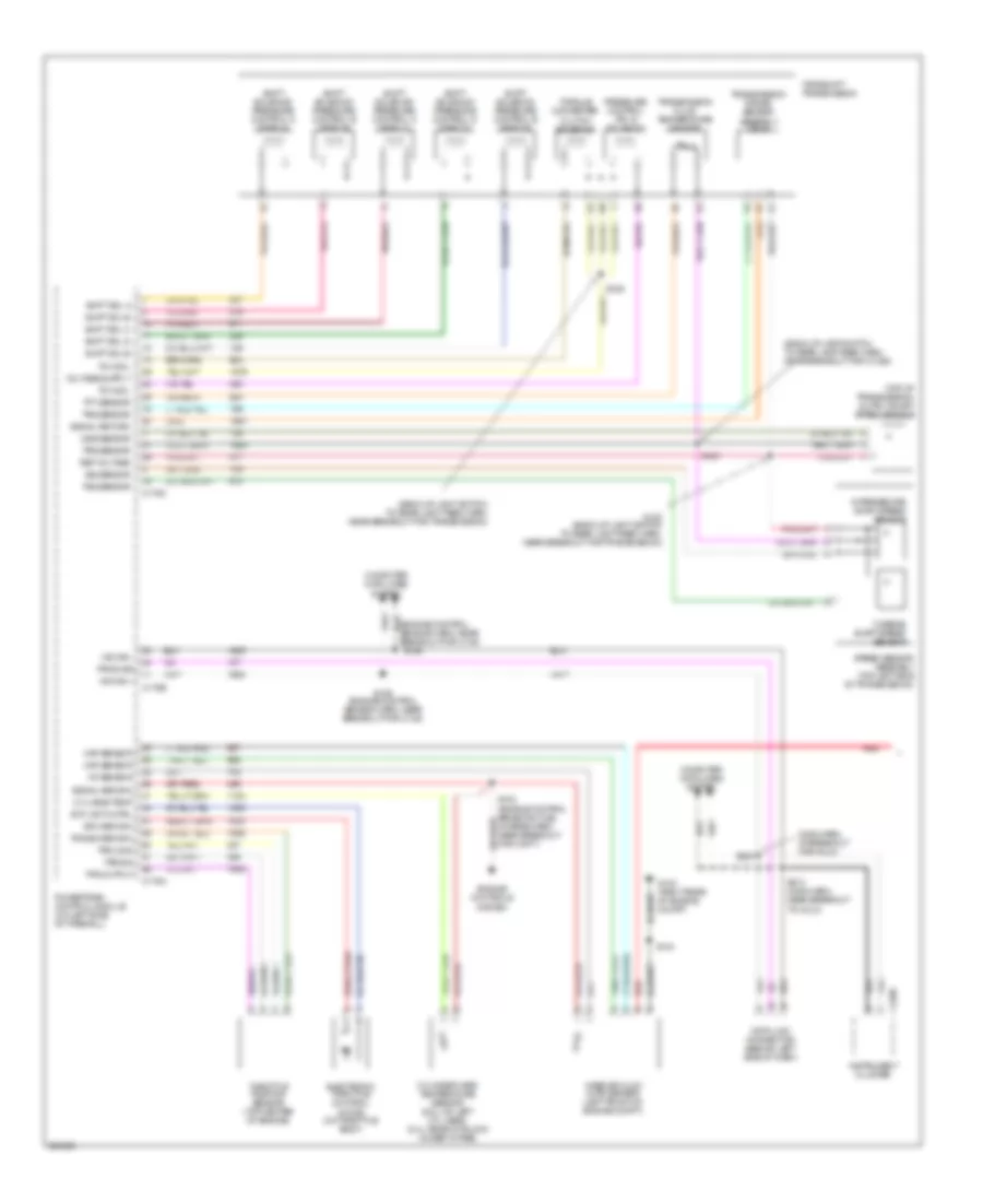
6.8L, A/T Wiring Diagram (2 of 2) for Ford F550 Super Duty 2005
List of elements for 6.8L, A/T Wiring Diagram (2 of 2) for Ford F550 Super Duty 2005:
- (engine control harn, near breakout for g101) s115
- (engine control sensor and fuel charge harn, near breakout to c188) s137
- (engine control sensor harn, near breakout for c1756) s123
- (main harn, at breakout for c218)
- (main harn, at breakout for c2186)
- (not used)
- 5.4l
- 6.8l
- Abs control module (left rear of engine compt)
- Abs system
- Acc
- Accelerator pedal position (app) sensor (on accelerator pedal support)
- App sensor 2 pwr
- App sensor 2 rtn
- App sensor 2 sig
- App sensor 3 pwr
- App sensor 3 rtn
- App sensor 3 sig
- Battery junction box (bjb) (left rear of engine compt)
- Bpp sw
- Brake pedal position switch (on bracket, above brake pedal)
- Brake shift interlock, four wheel drive control module
- C135
- C175a
- C175b
- C2256
- C270a
- C270c
- C270f
- C270h
- Central junction box (cjb) (behind lower left side of dash)
- Electronic automatic temperature control module
- Engine controls system
- Evap canister vent control solenoid
- Fuse 10a
- Fuse 15a
- Fuse 20a
- G100 (at left rear of engine compt)
- G100 (left rear of engine compt)
- G102 (right rear of engine compt)
- Ground
- Hot at all times
- Ignition (st/run)
- Ignition switch
- Lock
- Near breakout to brake pedal position switch)
- Near breakout to instrument cluster)
- Off
- Pcm ap sensor
- Pcm power diode
- Pcm power relay
- Pedal position switch)
- Powertrain control module (left rear of engine compt, near brake master cylinder)
- Red
- Run
- S106
- S127 (in back-up lamp switch to rear lamp feed harn, near breakout for c1385)
- S162
- S164 (engine control sensor harn, in breakout to c140)
- S221
- S223
- Start
- Tan
- Vbatt
- Vss +

 Čeština
 Dansk
Dansk Deutsch
 Ελληνικά
 English
 English
 Español
 Suomi
Suomi Français
 Français
 עברית
עברית Hrvatski
 Magyar
 日本語
日本語 한국어
한국어 Nederlands
 Polski
 Português
 Português
 Română
 Русский
 Slovenčina
 Slovenščina
 Svenska
 Türkçe
 中文 (中国)