AIR CONDITIONING
3.8L
3.8L VIN K, Compressor Wiring Diagram for Pontiac Firebird Formula 2002
 https://portal-diagnostov.com/license.html
Automotive Electricians Portal FZCO
Automotive Electricians Portal FZCO
https://portal-diagnostov.com/license.html
https://portal-diagnostov.com/license.html
Automotive Electricians Portal FZCO
Automotive Electricians Portal FZCO
List of elements for 3.8L VIN K, Compressor Wiring Diagram for Pontiac Firebird Formula 2002:
- (bottom) (left front of engine compt)
- (engine harn, 8 cm from pcm breakout)
- (forward lamp harn, 14 cm from pcm breakout)
- +5v
- A/c clutch rly
- A/c compressor clutch
- A/c compressor clutch diode (engine harn, near fuel injector 2 breakout)
- A/c compressor clutch relay
- A/c refrigerant pressure sensor (near right shock tower, on a/c evaporator hose)
- A/c request sig
- A/c sensor sig
- A/c-cruise fuse 15a
- At generator breakout)
- Bi-lv
- C10
- D10
- Def
- Engine controls system
- G112 (left rear of engine)
- Hot in run
- Hot in run, bulb test or start
- Htr
- Htr/def
- Hvac control assembly
- Hvac fuse 6 20a
- I/p fuse block (behind left side of dash)
- Max
- Mode switch
- Nca
- Norm
- Off
- Pnk
- Powertrain control module (in engine compt, behind right strut tower)
- S111
- S114 (engine harn, 3 cm back from generator breakout)
- S121
- S165 (forward lamp harn, 7 cm from junction block 2 breakout)
- S248 (dash harn, 2 cm from drl module breakout)
- Sensor ground
- Underhood fuse block
- Vent
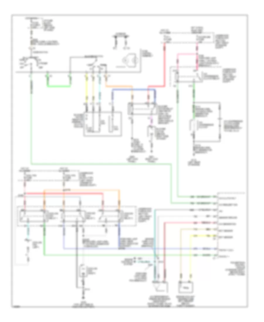
3.8L VIN K, Manual A/C Wiring Diagram for Pontiac Firebird Formula 2002
List of elements for 3.8L VIN K, Manual A/C Wiring Diagram for Pontiac Firebird Formula 2002:
- (bottom) (left front of engine compt)
- (engine harn, 8 cm from pcm breakout)
- (forward lamp harn, 14 cm from pcm breakout)
- (forward lamp harn, near right radiator support) s166
- +5v
- 0.31 ohm
- 0.61 ohm
- 1.85 ohm
- A/c clutch rly
- A/c compressor clutch
- A/c compressor clutch diode (engine harn, near breakout to fuel inj 2)
- A/c compressor clutch relay
- A/c refrigerant pressure sensor (near right shock tower, on a/c evaporator hose)
- A/c request sig
- A/c sensor sig
- A/c-cruise fuse 15a
- B10
- Bi-lv
- Blower motor (behind right side of dash)
- Blower motor relay (center of dash, on inflatable restraint dash module bracket)
- Blower motor resistor assembly (in hvac module)
- Blower switch
- C tan
- C10
- Cool fan fuse 10a
- Cool fan fuse 40a
- Cooling fan (left)
- Cooling fan (right)
- Cooling fan relay 1
- Cooling fan relay 2
- Cooling fan relay 3
- D10
- Def
- Ect sensor
- Engine controls system
- Engine coolant temperature (ect) sensor (below throttle body)
- Fan rly 1
- Fan rly 2 & 3
- G106 (top left side of radiator support)
- G112 (left rear of engine)
- G200 (left kick panel)
- G201 (right kick panel)
- High
- Hot at all times
- Hot in run
- Hot in run, bulb test or start
- Htr
- Htr/def
- Hvac control assembly
- Hvac fuse 6 20a
- I/p 1 fuse 40a
- I/p fuse block (behind left side of dash)
- Interior lights system
- Max
- Mode switch
- Nca
- Norm
- Off
- Pnk
- Powertrain control module (in engine compt, behind right strut tower)
- Red
- S111
- S113
- S115 (engine harn, at generator breakout)
- S121
- S165 (forward lamp harn, 7 cm from junction block 2 breakout)
- S169
- S179
- S216 (dash harn, 10 cm from cluster breakout)
- S248 (dash harn, 2 cm from drl module breakout)
- Sensor ground
- Tan
- Underhood fuse block
- Underhood fuse block (top) (left front corner of engine compt)
- Vent
5.7L
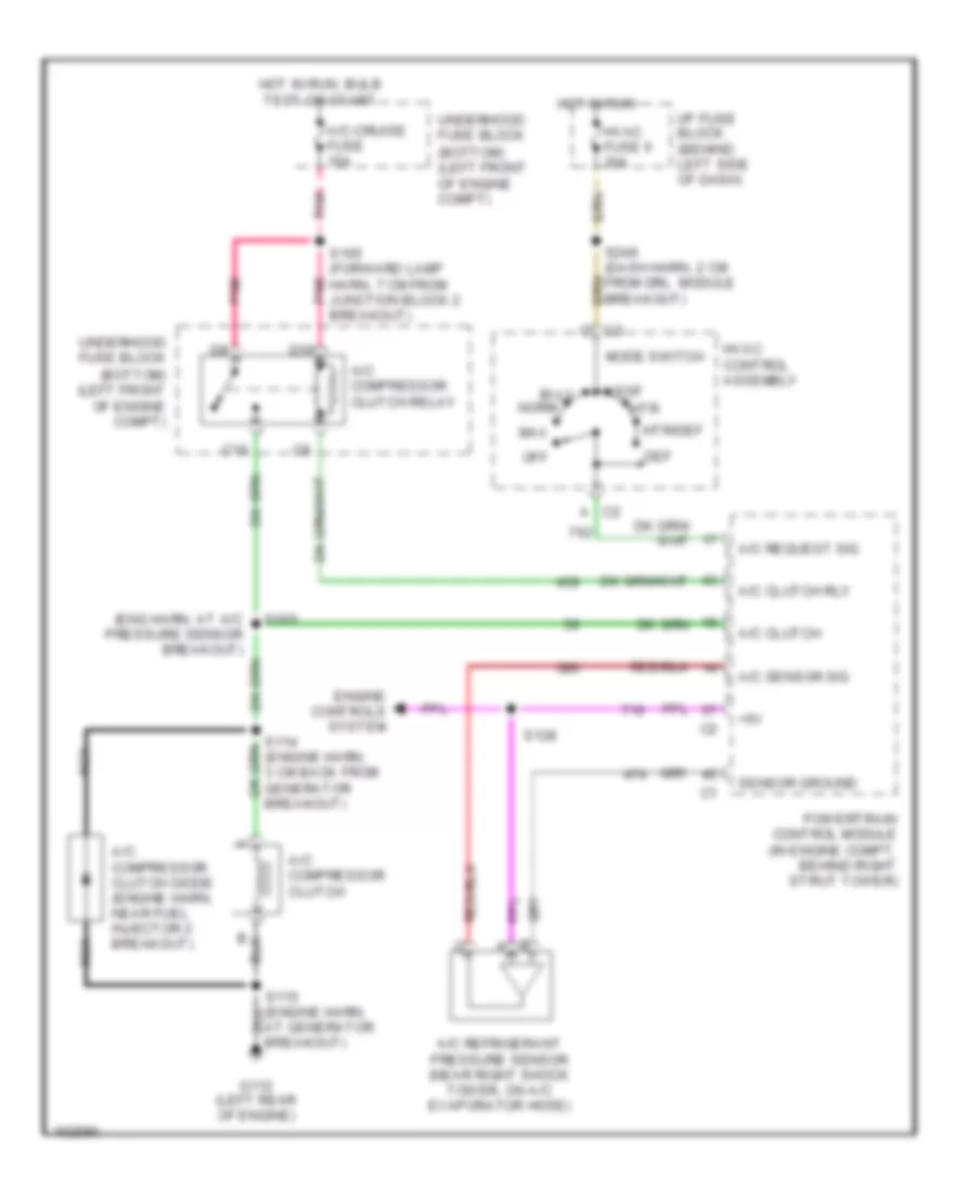
5.7L VIN G, Compressor Wiring Diagram for Pontiac Firebird Formula 2002
List of elements for 5.7L VIN G, Compressor Wiring Diagram for Pontiac Firebird Formula 2002:
- (bottom) (left front of engine compt)
- (eng harn, at a/c pressure sensor breakout)
- +5v
- A/c clutch
- A/c clutch rly
- A/c compressor clutch
- A/c compressor clutch diode (engine harn, near fuel injector 2 breakout)
- A/c compressor clutch relay
- A/c refrigerant pressure sensor (near right shock tower, on a/c evaporator hose)
- A/c request sig
- A/c sensor sig
- A/c-cruise fuse 15a
- At generator breakout)
- Bi-lv
- C10
- D10
- Def
- Engine controls system
- G112 (left rear of engine)
- Hot in run
- Hot in run, bulb test or start
- Htr
- Htr/def
- Hvac control assembly
- Hvac fuse 6 20a
- I/p fuse block (behind left side of dash)
- Max
- Mode switch
- Nca
- Norm
- Off
- Pnk
- Powertrain control module (in engine compt, behind right strut tower)
- S105
- S114 (engine harn, 3 cm back from generator breakout)
- S128
- S165 (forward lamp harn, 7 cm from junction block 2 breakout)
- S248 (dash harn, 2 cm from drl module breakout)
- Sensor ground
- Underhood fuse block
- Vent
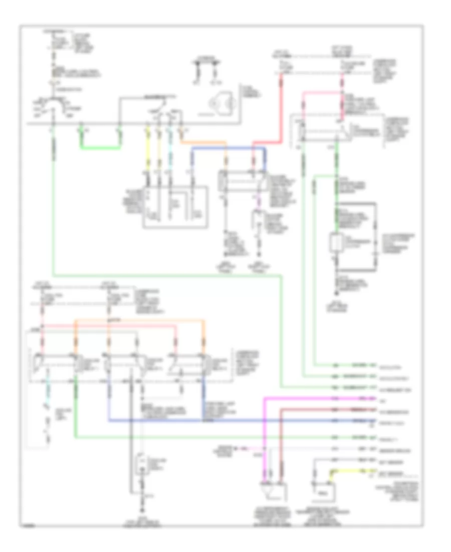
5.7L VIN G, Manual A/C Wiring Diagram for Pontiac Firebird Formula 2002
List of elements for 5.7L VIN G, Manual A/C Wiring Diagram for Pontiac Firebird Formula 2002:
- (bottom) (left front of engine compt)
- (forward lamp harn, near right radiator support) s166
- +5v
- 0.31 ohm
- 0.61 ohm
- 1.85 ohm
- A/c clutch
- A/c clutch rly
- A/c compressor clutch
- A/c compressor clutch diode (in a/c compressor harness)
- A/c compressor clutch relay
- A/c refrigerant pressure sensor (near right shock tower, on a/c evaporator hose)
- A/c request sig
- A/c sensor sig
- A/c-cruise fuse 15a
- B10
- Bi-lv
- Blower motor (behind right side of dash)
- Blower motor relay (center of dash, on inflatable restraint dash module bracket)
- Blower motor resistor assembly (in hvac module)
- Blower switch
- C tan
- C10
- Cool fan fuse 10a
- Cool fan fuse 40a
- Cooling fan (left)
- Cooling fan (right)
- Cooling fan relay 1
- Cooling fan relay 2
- Cooling fan relay 3
- D10
- Def
- Ect sensor
- Engine controls system
- Engine coolant temperature (ect) sensor (lower left side of engine, above generator)
- Fan rly 1
- Fan rly 2 & 3
- G108 (top left side of radiator support)
- G112 (left rear of engine)
- G200 (left kick panel)
- G201 (right kick panel)
- Hot at all times
- Hot in run
- Hot in run, bulb test or start
- Htr
- Htr/def
- Hvac control assembly
- Hvac fuse 6 20a
- I/p 1 fuse 40a
- I/p fuse block (behind left side of dash)
- Interior lights system
- Max
- Mode switch
- Nca
- Norm
- Off
- Pnk
- Powertrain control module (pcm) (in engine compt, behind right strut tower)
- Red
- S105 (engine harn, at ac/ press sensor)
- S113
- S115 (engine harn, at generator breakout)
- S128
- S165 (forward lamp harn, 7 cm from junction block 2 breakout)
- S169
- S179
- S216 (dash harn, 10 cm from cluster breakout)
- S248 (dash harn, 2 cm from drl module breakout)
- Sensor ground
- Tan
- Underhood fuse block
- Underhood fuse block (top) (left front corner of engine compt)
- Vent

 Čeština
 Dansk
Dansk Deutsch
 Ελληνικά
 English
 English
 Español
 Suomi
Suomi Français
 Français
 עברית
עברית Hrvatski
 Magyar
 日本語
日本語 한국어
한국어 Nederlands
 Polski
 Português
 Português
 Română
 Русский
 Slovenčina
 Slovenščina
 Svenska
 Türkçe
 中文 (中国)