ANTI-LOCK BRAKES
Anti-Lock Brakes Wiring Diagram for GMC Sierra Classic 2500 HD 2007
 https://portal-diagnostov.com/license.html
Automotive Electricians Portal FZCO
Automotive Electricians Portal FZCO
https://portal-diagnostov.com/license.html
https://portal-diagnostov.com/license.html
Automotive Electricians Portal FZCO
Automotive Electricians Portal FZCO
List of elements for Anti-Lock Brakes Wiring Diagram for GMC Sierra Classic 2500 HD 2007:
- (diesel)
- (gas)
- (gas: left rear of eng block) (diesel: right front of eng block)
- (in i/p harness) sp205
- 3.6k ohms
- A10
- Abs fuse 60a
- Abs ind
- Allison
- B10
- Brake fluid level sw in
- Brake fluid level switch (on left side of brake fluid reservoir)
- Brake fuse 10a
- Brake ind
- Brake input
- C12
- C2 b7
- C5 c1
- C9 a
- Clutch start switch (m/t) (top of clutch clutch assy)
- Cpp sw sig
- Data link connector (dlc) (below steering column)
- Del torque sig
- Electronic brake control module (ebcm) (on left side of inner frame)
- Except allison
- Except seo
- Front axle act/sw input
- G104
- G110 (left front body mount)
- G203 (near left "a" pillar)
- Hot at all times
- Hot in run
- Hot in run or start
- I/p fuse block (on lower left side of dash)
- Ign e fuse 10a
- Ignition
- Instrument planel cluster
- Interior lights system
- Left front sensor (+)
- Left front sensor (-)
- Left front wheel speed sensor
- Logic
- Nca
- Pnk
- Powertrain or engine control module (pcm or ecm) (on left front of eng compt)
- Red
- Req torque sig
- Right front sensor (+)
- Right front sensor (-)
- Right front wheel speed sensor
- S102
- S213
- Seo
- Seo ign fuse 10a
- Serial data
- Stoplamp switch (on top of brake pedal bracket)
- Tan
- Tcc brake sw
- Traction control ind (if equipped)
- Traction control switch (if equipped)
- Transfer case shift control module (behind headlamp switch)
- Transmission control module (tcm) (left front of eng compt)
- Transmissions system (allison)
- Transmissions system (transfer case circuit)
- Underhood fuse block (at left side of engine compt)
- Vehicle speed sensor (vss) (nv 4500: left side of transmission, nvg 261-np2: left side of transfer case, nvg 263-np1: left rear of transfer case, zf s6-650: left rear of transmission, 4l60-e: right rear of transmission)
- Vss high
- Vss input
- Vss low
- Vss output
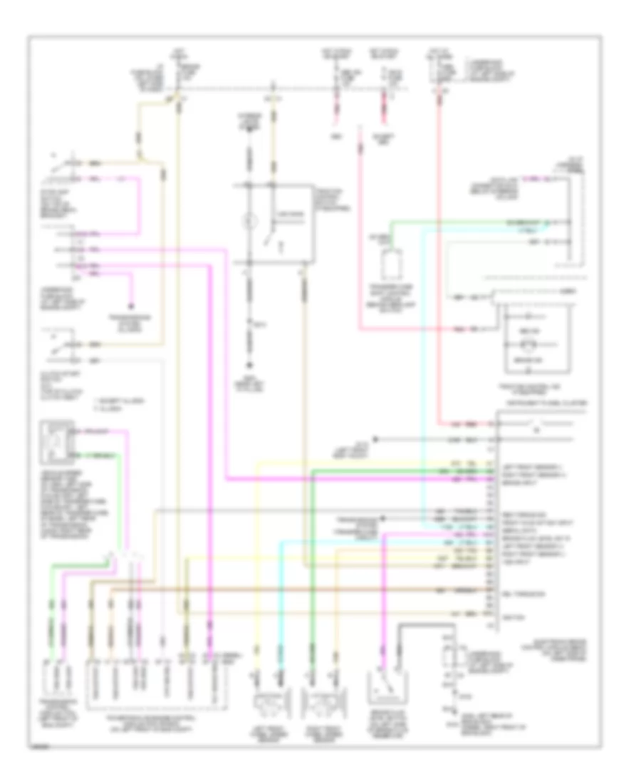
Anti-Lock Brakes Wiring Diagram, with Rear Disc Brakes for GMC Sierra Classic 2500 HD 2007
List of elements for Anti-Lock Brakes Wiring Diagram, with Rear Disc Brakes for GMC Sierra Classic 2500 HD 2007:
- 3.6k ohms
- Abs fuse 60a
- Abs ind
- Brake fluid level sw in
- Brake fuse 10a
- Brake in
- Brake ind
- Brake input
- Brake pressure differential switch (under master cylinder)
- C12
- C2 b7
- C5 c1
- C9 a
- Clutch start switch (m/t) (top of clutch clutch assy)
- Data link connector (dlc) (below steering column)
- Del torque
- Delivered torque
- Electronic brake control module (ebcm) (on left side of inner frame)
- Except seo
- G104 (left rear of engine block)
- G110 (left front body mount)
- G203 (near left "a" pillar)
- Hot at all times
- Hot in run
- Hot in run or start
- I/p fuse block (on lower left side of dash)
- Ign e fuse 10a
- Ignition
- Instrument panel cluster
- Interior lights system
- Left front sensor (+)
- Left front sensor (-)
- Left front wheel speed sensor
- Logic
- Nca
- Pnk
- Powertrain control module (pcm) (on left front of engine compt)
- Red
- Req torque
- Requested torque
- Right front sensor (+)
- Right front sensor (-)
- Right front wheel speed sensor
- S102
- S213
- Seo
- Seo ign fuse 10a
- Serial data
- Sp205 (in i/p harness)
- Stoplamp switch (on top of brake pedal bracket)
- Tan
- Tcc brake sw
- Trac sw input
- Traction control ind (if equipped)
- Traction control switch (if equipped)
- Transfer case shift control module (behind headlamp switch)
- Transmissions system (transfer case circuit)
- Underhood fuse block (at left side of eng compt)
- Underhood fuse block (at left side of engine compt)
- Vehicle speed sensor (vss) (nv 4500: left side of transmission, nvg 261-np2: left side of transfer case, nvg 263-np1: left rear of transfer case, zf s6-650: left rear of transmission, 4l60-e: right rear of transmission)
- Vss high
- Vss input
- Vss low
- Vss out
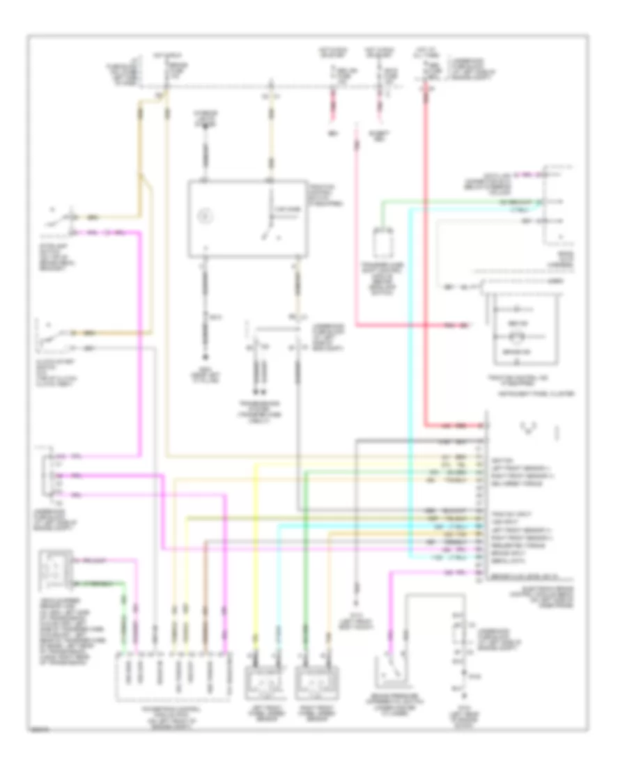
Anti-Lock Brakes Wiring Diagram, with Rear Drum Brakes for GMC Sierra Classic 2500 HD 2007
List of elements for Anti-Lock Brakes Wiring Diagram, with Rear Drum Brakes for GMC Sierra Classic 2500 HD 2007:
- (diesel)
- (gas)
- (gas: left rear of eng block) (diesel: right front of eng block)
- (in i/p harness) sp205
- 3.6k ohms
- A10
- Abs fuse 60a
- Abs ind
- Allison
- B10
- Brake fluid level sw in
- Brake fluid level switch (on left side of brake fluid reservoir)
- Brake fuse 10a
- Brake ind
- Brake input
- C12
- C2 b7
- C5 c1
- C9 a
- Clutch start switch (m/t) (top of clutch clutch assy)
- Cpp sw sig
- Data link connector (dlc) (below steering column)
- Del torque sig
- Electronic brake control module (ebcm) (on left side of inner frame)
- Except allison
- Except seo
- Front axle act/sw input
- G104
- G110 (left front body mount)
- G203 (near left "a" pillar)
- Hot at all times
- Hot in run
- Hot in run or start
- I/p fuse block (on lower left side of dash)
- Ign e fuse 10a
- Ignition
- Instrument planel cluster
- Interior lights system
- Left front sensor (+)
- Left front sensor (-)
- Left front wheel speed sensor
- Logic
- Nca
- Pnk
- Powertrain or engine control module (pcm or ecm) (on left front of eng compt)
- Red
- Req torque sig
- Right front sensor (+)
- Right front sensor (-)
- Right front wheel speed sensor
- S102
- S213
- Seo
- Seo ign fuse 10a
- Serial data
- Stoplamp switch (on top of brake pedal bracket)
- Tan
- Tcc brake sw
- Traction control ind (if equipped)
- Traction control switch (if equipped)
- Transfer case shift control module (behind headlamp switch)
- Transmission control module (tcm) (left front of eng compt)
- Transmissions system (allison)
- Transmissions system (transfer case circuit)
- Underhood fuse block (at left side of engine compt)
- Vehicle speed sensor (vss) (nv 4500: left side of transmission, nvg 261-np2: left side of transfer case, nvg 263-np1: left rear of transfer case, zf s6-650: left rear of transmission, 4l60-e: right rear of transmission)
- Vss high
- Vss input
- Vss low
- Vss output
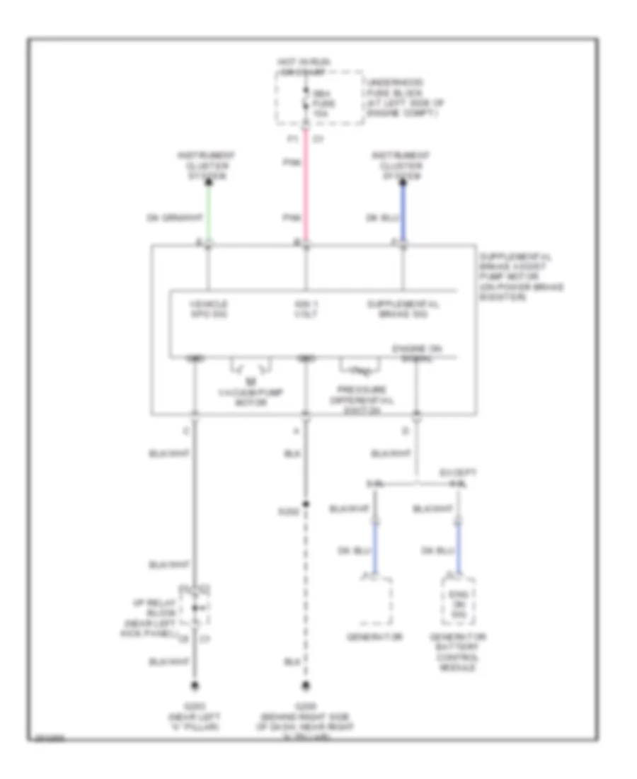
Supplemental Brake Assist Wiring Diagram for GMC Sierra Classic 2500 HD 2007
List of elements for Supplemental Brake Assist Wiring Diagram for GMC Sierra Classic 2500 HD 2007:
- 6.0l
- C1 f5
- C5 c1
- Eng on sig
- Engine on signal
- Except 6.0l
- G200 (behind right side of dash, near right "a" pillar)
- G203 (near left "a" pillar)
- Generator
- Generator battery control module
- Grd
- Hot in run or start
- I/p relay block (near left kick panel)
- Ign 1 volt
- Instrument cluster system
- Pnk
- Pressure differential switch
- S202
- Sba fuse 15a
- Underhood fuse block (at left side of engine compt)
- Vacuum pump motor
- Vehicle spd sig

 Čeština
 Dansk
Dansk Deutsch
 Ελληνικά
 English
 English
 Español
 Suomi
Suomi Français
 Français
 עברית
עברית Hrvatski
 Magyar
 日本語
日本語 한국어
한국어 Nederlands
 Polski
 Português
 Português
 Română
 Русский
 Slovenčina
 Slovenščina
 Svenska
 Türkçe
 中文 (中国)