COOLING FAN
Cooling Fan Wiring Diagram for Pontiac Vibe GT 2006
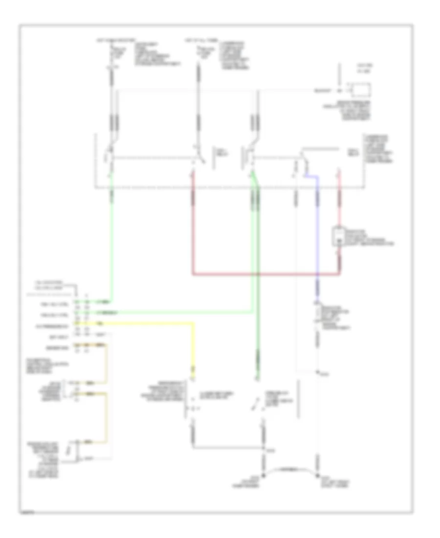
List of elements for Cooling Fan Wiring Diagram for Pontiac Vibe GT 2006:
- 1.8l (vin 8) fwd
- 1.8l (vin l) awd
- A/c pressure sw
- Brake pressure modulator valve (bpmv) (at right front side of engine compartment)
- Closed between 28 psi & 455 psi
- Ect input
- Ecu-ig fuse 10a
- Engine coolant temperature (ect) sensor (1.8l (vin l): at rear of engine) (1.8l (vin 8): at left side of cylinder head)
- Fan 1 relay
- Fan 1 rly ctrl
- Fan 2 relay
- Fan 2 rly ctrl
- G102 (on right inner fender)
- G103 (at left front strut tower)
- Hot at all times
- Hot in run or start
- Instrument panel fuse block (left of steering column, behind storage compartment)
- Open below 178 psi closed above 220 psi
- Powertrain control module (pcm) (behind right side of dash)
- Radiator fan motor (at front of engine compt, behind radiator)
- Radiator fan resistor (at left front of engine compartment)
- Rdi fan fuse 40a
- Refrigerant pressure switch (at right side of engine compartment, on receiver drier)
- S102
- S103
- Sensor gnd
- Sp108 (in engine accessory harness, near pcm)
- Underhood fuse block (left side of engine compartment, mounted to inner fender)
- W/ vsc
- W/o vsc
 Čeština
 Dansk
Dansk Deutsch
 Ελληνικά
 English
 English
 Español
 Suomi
Suomi Français
 Français
 עברית
עברית Hrvatski
 Magyar
 日本語
日本語 한국어
한국어 Nederlands
 Polski
 Português
 Português
 Română
 Русский
 Slovenčina
 Slovenščina
 Svenska
 Türkçe
 中文 (中国)
 Italiano