ENGINE PERFORMANCE
2.9L
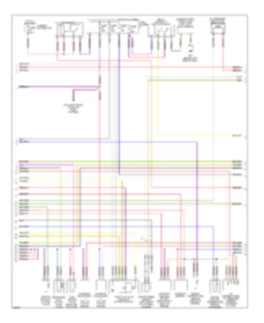
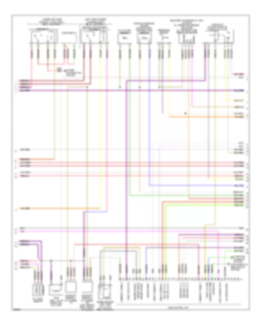
2.9L, Engine Performance Wiring Diagram (1 of 3) for Porsche Boxster S 2011
 https://portal-diagnostov.com/license.html
Automotive Electricians Portal FZCO
Automotive Electricians Portal FZCO
https://portal-diagnostov.com/license.html
https://portal-diagnostov.com/license.html
Automotive Electricians Portal FZCO
Automotive Electricians Portal FZCO
List of elements for 2.9L, Engine Performance Wiring Diagram (1 of 3) for Porsche Boxster S 2011:
- +5v
- B+ plug socket (right side of trans- mission)
- Battery
- Before cat heat o2s1
- Before cat heat o2s2
- Before cat o2s 1 gnd
- Before cat o2s 1 sig
- Before cat o2s 2 gnd
- Before cat o2s 2 sig
- Behind cat heat o2s1
- Behind cat heat o2s2
- Behind cat o2s 1 gnd
- Behind cat o2s 1 sig
- Behind cat o2s 2 gnd
- Behind cat o2s 2 sig
- Camshaft sensor 1
- Camshaft sensor 2
- Can hi display
- Can lo display
- Clock sig
- Computer data lines system
- Current
- Diagnostic test con
- Dme control unit
- Electronics gnd
- Eng compt temp sen
- Eng speed sens shd
- Final stage gnd
- Flap over valve
- Fuse f3 7.5a
- Fuse holder d
- Generator
- Generator term
- Gp8 (at left side of engine compt)
- Gp9 (at left side of eng compt)
- Ground
- Hfm +5v
- Hfm gnd
- Hot at all times
- Htr +
- Htr -
- Inj valve/cylinder 3
- Inj valve/cylinder 4
- Inj valve/cylinder 5
- Inj valve/cylinder 6
- Injectors gnd
- Instrument cluster
- Intake temp sensor
- Lift control valve cylinders 1-3 (cylinder head cover)
- Lift control valve cylinders 4-6 (cylinder head cover)
- Lift ctrl cyl 1-3
- Lift ctrl cyl 4-6
- Maf signal
- Mass air flow sensor
- Maxi fuse 40a
- Nca
- Ntc coolant temp
- Oxygen sensor (cyl 1-3)
- Oxygen sensor (cyl 4-6)
- Oxygen sensor ahead of catalytic converter
- Pipe distribution flap valve
- Pipe flap
- Pressure ctrl +
- Pump current reg in
- Pump current reg out
- Red
- Resistor
- Second air pump rly
- Secondary air pump (net to intake bridge)
- Secondary air pump rear maxi fuse (left side of engine compt, on on fuses support)
- Secondary air pump relay (relay support 2)
- Sensors gnd
- Sports exhaust sys
- Starter
- Starting/ charging system
- Tank venting valve
- Temp motor oil
- Term 15
- Term 30
- Term 87
- Throttle valve gnd
- Throttle valve sig
- Throttle vlv mtr (+)
- Throttle vlv mtr (-)
- Volt +
- Volt -
- Voltage
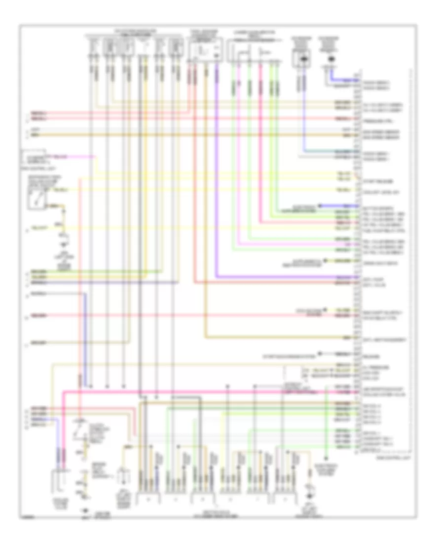
2.9L, Engine Performance Wiring Diagram (2 of 3) for Porsche Boxster S 2011
List of elements for 2.9L, Engine Performance Wiring Diagram (2 of 3) for Porsche Boxster S 2011:
- (relay support 1) fuel pump relay
- (under battery, in fuel tank) fuel pump/ level sensor
- Air conditioning & cooling fans systems
- Camshaft adjustment (cyl 1-3) (top of engine)
- Camshaft adjustment (cyl 4-6) (top of engine)
- Camshaft sensor 1
- Camshaft sensor 2 (at left rear & right front of engine)
- Current distributor
- Engine coolant temperature sensor (on engine)
- Engine speed sensor (left side of clutch bell housing)
- Engine temperature sensor (middle of engine)
- Fuse f1 25a
- Fuse f5 25a
- Fuse f6 25a
- Fuse f7 15a
- Fuse f7 80a
- Fuse holder d
- Gnd
- Gp3 (behind left side of dash)
- Hot at all times
- Mfi-di relay
- Nca
- Ntc
- Oil pressure regulation shift valve
- Oil temperature & oil pressure sensor (on engine oil pan)
- Resonance flap switch over valve
- Sig
- Sports exhaust system valve
- Tank venting valve (near fuel fill flap)
- Throttle valve (middle of intake manifold)
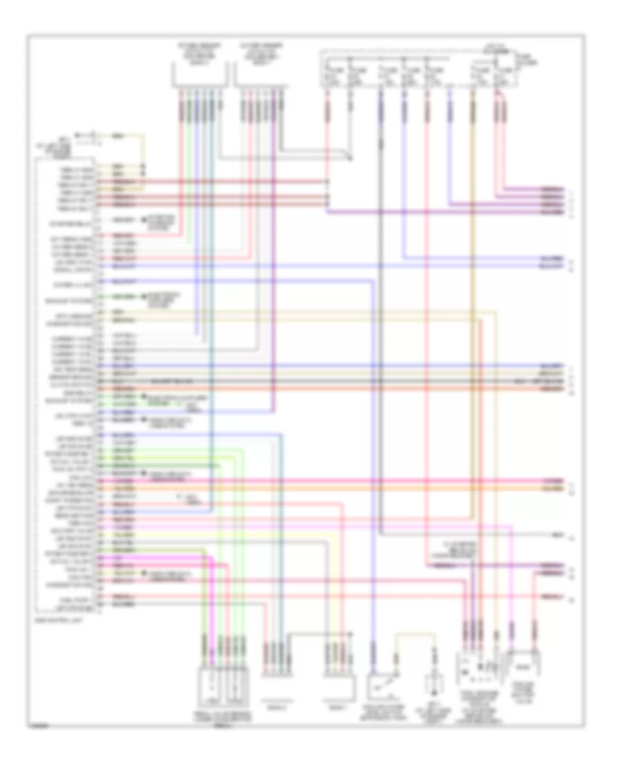
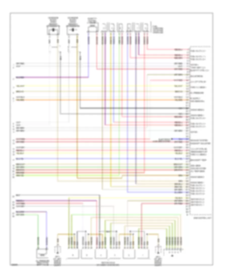
2.9L, Engine Performance Wiring Diagram (3 of 3) for Porsche Boxster S 2011
List of elements for 2.9L, Engine Performance Wiring Diagram (3 of 3) for Porsche Boxster S 2011:
- (center of dash)
- (expansion tank) cooling water level switch
- (on engine block) knock sensor 1
- (on engine block) knock sensor 2
- (on intake manifolds) fuel injectors
- (under accelerator pedal) pedal valve sensor
- +5v pdl value sens 1
- +5v pdl value sens 2
- Bridge plug (relay support 1)
- Button sports
- Camshaft adj 1
- Camshaft adj 2
- Can high
- Can low
- Clutch interlock switch (clutch pedal)
- Coolant level sw
- Cooling fans system
- Cooling water valve
- Crash shut-down
- Dme control unit
- Dmtl heating element
- Dmtl pump
- Dmtl valve
- Electronic mufflers system
- Eng compt blwr rly
- Eng speed sensor
- Fuel pump relay ctrl
- Gateway control unit (left kick panel)
- Gp11 (at left side of engine compt)
- Gp4
- Gp9 (left side of engine compt)
- Ign coil 1
- Ign coil 2
- Ign coil 3
- Ign coil 4
- Ign coil 5
- Ign coil 6
- Ignition coils (cylinder head cover)
- Inj valve/cylinder 1
- Inj valve/cylinder 2
- Knock sens 1
- Knock sens 2
- Led sports exhaust
- Mfi+di relay ctrl
- Oil pressure
- Pdk control unit
- Pdl value sens 1 gnd
- Pdl value sens 1 sig
- Pdl value sens 2 gnd
- Pdl value sens 2 sig
- Plug spark
- Pressure ctrl -
- Release
- Spark plug
- Start release
- Starter inter lk a
- Starting/charging system
- Tank leakage diagnostics module
3.4L
3.4L, Engine Performance Wiring Diagram (1 of 4) for Porsche Boxster S 2011
List of elements for 3.4L, Engine Performance Wiring Diagram (1 of 4) for Porsche Boxster S 2011:
- (not used)
- +5v veh sens
- Actual value 1
- Actual value 2
- Air temp sens
- Bank 1
- Bank 2
- Can high
- Can low
- Clutch switch
- Compt purge fan
- Computer data lines system
- Cooling water level switch (expansion tank)
- Cooling water shutoff valve
- Current vk b1
- Current vk b2
- Diagnostics mod
- Dme control unit
- Dme relay
- Dmtl-heizung
- Electronic mufflers system
- Exhaust system
- Fuel pump 1
- Fuse f1 25a
- Fuse f3 7.5a
- Fuse f4 20a
- Fuse f5 25a
- Fuse f6 25a
- Fuse f7 15a
- Fuse f8 7.5a
- Fuse holder d
- Gp11 (at left side of engine compt)
- Hot at all times
- Lsf gnd nk b1
- Lsf gnd nk b2
- Lsf htr nk b1
- Lsf htr nk b2
- Lsf sig nk b1
- Lsf sig nk b2
- Lsu gnd vk b1
- Lsu htr vk b1
- Oxy sens 2 gnd
- Oxygen sens 1
- Oxygen sens 2
- Oxygen sensor catalytic converter 1 bank 1
- Oxygen sensor catalytic converter bank 2
- Pedal valve sensor (under accelerator pedal)
- Potentiometer 1
- Potentiometer 2
- Pwg +5v 1
- Pwg +5v poti 2
- Scavenge blwr
- Sens heating
- Sensor ground
- Shutoff valve
- Signal, maf b1
- Starter relay
- Starting/ charging system
- Tank leakage diagnostics module (w/ on board refueling vapor recovery)
- Term 15
- Term 30a
- Term 31 gnd
- Term 87 sply
- W/ on board refueling vapor recovery
- Water lvl sw
3.4L, Engine Performance Wiring Diagram (2 of 4) for Porsche Boxster S 2011
List of elements for 3.4L, Engine Performance Wiring Diagram (2 of 4) for Porsche Boxster S 2011:
- (under battery, in fuel tank) fuel pump/ level sensor
- A/t
- Bridge plug (relay support 1)
- Camshaft adjustment 1 cylinders 1-3 (top of engine)
- Camshaft adjustment 2 cylinders 4-6 (top of engine)
- Can high instrument cluster
- Can low
- Clutch interlock switch (clutch pedal)
- Computer data lines system
- Distribution pipe flap valve
- Engine compartment purge fan
- Fuel lvl sens
- Fuel pump relay 1
- Fuse f1 10a
- Fuse holder f
- Gnd
- Gp11 (at left side of engine compt)
- Gp3 (behind left side of dash)
- Gp4 (center of dash)
- Hot at all times
- Intake pipe flap valve (front middle middle of engine)
- Lift control valve cylinders 1-3 (cylinder head cover)
- Lift control valve cylinders 4-6 (cylinder head cover)
- M/t
- Mass air flow sensor
- Ntc
- Oil level
- Oil level gnd
- Pdk control unit
- Relay support 1 (under left side of dash, in footwell)
- Signal
- Sply
- Starter interlock
- Volt ref
3.4L, Engine Performance Wiring Diagram (3 of 4) for Porsche Boxster S 2011
List of elements for 3.4L, Engine Performance Wiring Diagram (3 of 4) for Porsche Boxster S 2011:
- (boxster: on engine oil pan) (cayman) oil pressure sensor (boxster) oil temperature pressure sensor
- (left side of rear luggage compt) relay support 2
- (middle of engine) engine compartment temperature sensor
- (middle of intake manifold) throttle valve
- (under left side of dash, in footwell) relay support 1
- +5v
- Air cleaner flap
- Camshaft sens 1
- Camshaft sens 2
- Camshaft sensor 1 cylinders 1-3
- Camshaft sensor 2 cylinders 4-6 (left rear & right front of engine)
- Crash out
- Dme control unit
- Dme relay
- Engine compartment fan relay
- Engine shield
- Engine speed +
- Engine speed -
- Fuel inj cyl 2 -
- Fuel inj cyl 5 -
- Generator pwm
- Ground
- Ignition cyl 3
- Ignition cyl 4
- Ignition cyl 5
- Knock sensor 1
- Knock sensor 2
- Micro relay
- Nca
- Ntc
- Ntc water sensor
- Oil level sensor
- Oil regulation -
- Output
- Power distribution system
- Pressure sensor
- Regulation +
- Signal
- Speed sensor (left side of clutch bell housing)
- Starting/ charging system
- Tank vent valve (near fuel fill flap)
- Term 15
- Term 31
- Thro valve +5v
- Thro vlv gnd
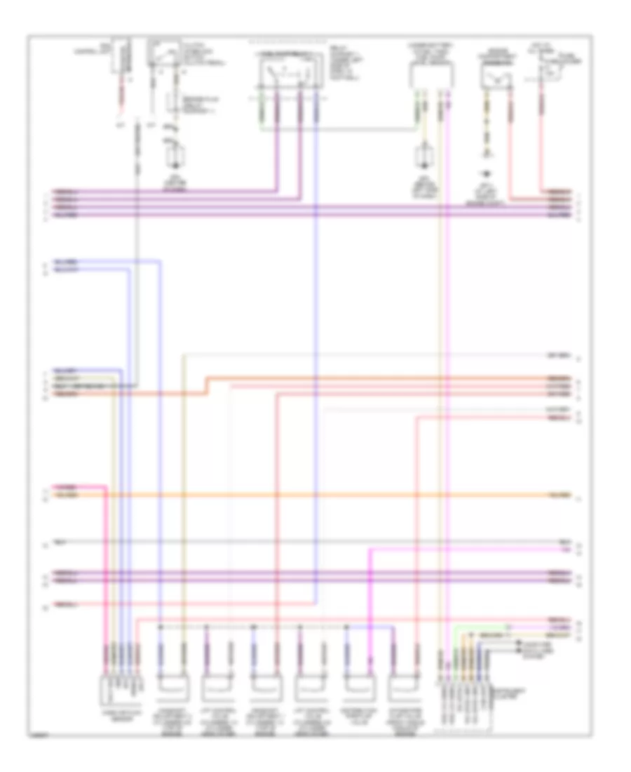
3.4L, Engine Performance Wiring Diagram (4 of 4) for Porsche Boxster S 2011
List of elements for 3.4L, Engine Performance Wiring Diagram (4 of 4) for Porsche Boxster S 2011:
- (on engine block) knock sensor 1 cylinders 1-3
- (on engine block) knock sensor 2 cylinders 4-6
- Adjuster b2
- Camshaft adjuster
- Cooling water
- Dme control unit
- Electronic mufflers system
- Eng compt temp
- Exhaust system
- Fuel inj cyl 1 +
- Fuel inj cyl 1 -
- Fuel inj cyl 2 +
- Fuel inj cyl 3 +
- Fuel inj cyl 3 -
- Fuel inj cyl 4 +
- Fuel inj cyl 4 -
- Fuel inj cyl 5 +
- Fuel inj cyl 6 +
- Fuel inj cyl 6 -
- Fuel injectors (on intake manifolds)
- Gnd, sens
- Gp11 (at left side of engine compt)
- High sens rail
- Ignition coils (cylinder head cover)
- Ignition cyl 1
- Ignition cyl 2
- Ignition cyl 6
- Knock sens 1
- Knock sens 2
- Motor +
- Motor -
- Nca
- Oil pressure
- Oil pressure regulation shift valve
- Oil temp sens
- Quantity control valve
- Quantity ctrl vlv
- Resonance flap
- Tank vent vlv
- Thro vlv sens 1
- Thro vlv sens 2
- Vlv lift ctrl b1
- Vlv lift ctrl b2

 Čeština
 Dansk
Dansk Deutsch
 Ελληνικά
 English
 English
 Español
 Suomi
Suomi Français
 Français
 עברית
עברית Hrvatski
 Magyar
 日本語
日本語 한국어
한국어 Nederlands
 Polski
 Português
 Português
 Română
 Русский
 Slovenčina
 Slovenščina
 Svenska
 Türkçe
 中文 (中国)