COOLING FAN
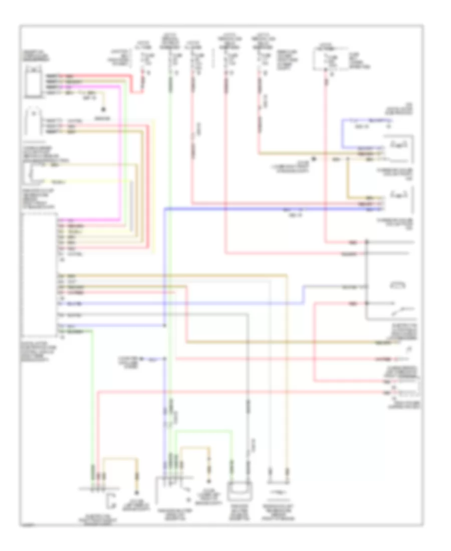
Cooling Fan Wiring Diagram for BMW 550xi GT 2013
List of elements for Cooling Fan Wiring Diagram for BMW 550xi GT 2013:
- (except m5) intercooler coolant pump
- (m5)
- Characteristic map thermostat (front of engine)
- Charge air cooler coolant pump (m5)
- Charge air cooler coolant pump 2 (m5)
- Computer data lines system
- Digital motor electronics (dme) control module (right rear engine compt)
- Digital motor electronics 2
- Electric fan (right front side of engine compt)
- Electric fan cutoff relay (right side of luggage compt)
- Engine coolant temperature sensor (front of engine)
- Front power distribution box
- Fuse 100a
- Fuse 10a
- Fuse 10a (m5)
- Fuse 15a
- Fuse 5a
- Fuse 7.5a
- Fuse box (under spare tire)
- Hot at all times
- Hot w/ terminal 15n relay energized
- Hot w/ terminal 30b relay energized
- Junction box (right side of dash)
- Nca
- Radiator outlet temperature sensor (right front of engine compt)
- Radiator shutter drive unit (except m5)
- Radiator shutter solenoid (except m5)
- Rear fuse holder (right side of rear compt)
- Red
- Turbocharger coolant pump (behind charge air cooling expansion tank)
- X148 1b
- X252 1b
- X697 1b
- Z10 15b (left rear of engine compt)
- Z10 2b (lower left front of engine compt)
- Z10 3b (lower right front of engine compt)
- Z6000 5b
 Čeština
 Dansk
Dansk Deutsch
 Ελληνικά
 English
 English
 Español
 Suomi
Suomi Français
 Français
 עברית
עברית Hrvatski
 Magyar
 日本語
日本語 한국어
한국어 Nederlands
 Polski
 Português
 Português
 Română
 Русский
 Slovenčina
 Slovenščina
 Svenska
 Türkçe
 中文 (中国)
 Italiano