ANTI-LOCK BRAKES
Anti-lock Brakes Wiring Diagram, with Electronic Stability Program for Saab 9-5 Linear 2004
 https://portal-diagnostov.com/license.html
Automotive Electricians Portal FZCO
Automotive Electricians Portal FZCO
https://portal-diagnostov.com/license.html
https://portal-diagnostov.com/license.html
Automotive Electricians Portal FZCO
Automotive Electricians Portal FZCO
List of elements for Anti-lock Brakes Wiring Diagram, with Electronic Stability Program for Saab 9-5 Linear 2004:
- (behind left side of dash) g40
- (in engine compt, on front of left wheelwell)
- (on steering column) steering wheel angle sensor
- Abs warning indicator
- Brake pressure sensor (mounted on abs hydraulic unit)
- Brake- light switch (on pedal bracket)
- C23-1
- Computer data lines system
- Dashboard main fuse board (behind left end of dash)
- Data link connector (under dash, near steering column)
- Engine bay main fuse board (behind battery)
- Esp control module
- Esp indicator
- Esp off indicator
- Esp switch
- Fuse 10a
- Fuse 15a
- Fuse 7.5a
- G2 (behind battery)
- G30
- G41s (center of dash, behind radio)
- Hot at all times
- Hot in run or start
- Illum
- Interior lights system
- Left front wheel speed sensor (on left front wheel hub assembly)
- Left rear wheel speed sensor (on left rear wheel hub assembly)
- Main instrument unit
- Maxi fuse 2 60a
- Navigation module
- Navigation system connector
- Nca
- Pnk
- R10-1
- R11-1
- R12-1
- R13-1
- R14-1
- R15-1
- R16-1
- R17-1
- R18-1
- R19-1
- R30-2
- R30-3
- R31-4
- R31-5
- R4-1
- R56-1
- R60
- R61
- R63
- R64
- R65
- R66
- R67
- Red
- Right front wheel speed sensor (on right front wheel hub assembly)
- Right rear wheel speed sensor (on right rear wheel hub assembly)
- Speed- ometer
- Trionic control module (in right rear of engine compt)
- Yaw rate sensor (under center console, ahead of gear lever assembly)
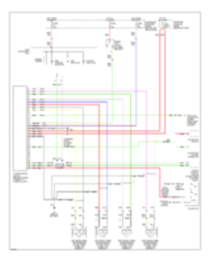
Anti-lock Brakes Wiring Diagram, with Traction Control for Saab 9-5 Linear 2004
List of elements for Anti-lock Brakes Wiring Diagram, with Traction Control for Saab 9-5 Linear 2004:
- (in engine compt, on front of left wheelwell)
- Abs warning indicator
- Brake- light switch (on pedal bracket)
- C23-1
- Computer data lines system
- Dashboard main fuse board (behind left end of dash)
- Data link connector (under dash, near steering column)
- E58-8
- E59-8
- Engine bay main fuse board (behind battery)
- Fuse 10a
- Fuse 15a
- Fuse 7.5a
- G2 (behind battery)
- G30
- G41s (center of dash, behind radio)
- Hot at all times
- Hot in run or start
- Illum
- Interior lights system
- Left front wheel speed sensor (on left front wheel hub assembly)
- Left rear wheel speed sensor (on left rear wheel hub assembly)
- Main instrument unit
- Maxi fuse 2 60a
- Navigation module
- Navigation system connector
- Nca
- Pnk
- R10-1
- R11-1
- R12-1
- R13-1
- R14-1
- R15-1
- R16-1
- R17-1
- R18-1
- R19-1
- R30-2
- R30-3
- R31-4
- R31-5
- R4-1
- R56
- Red
- Right front wheel speed sensor (on right front wheel hub assembly)
- Right rear wheel speed sensor (on right rear wheel hub assembly)
- Speedo- meter
- Tc-abs control module (behind battery, integral to hydraulic unit)
- Tcs indicator
- Tcs off indicator
- Tcs switch
- Trionic control module (in right rear of engine compt)

 Čeština
 Dansk
Dansk Deutsch
 Ελληνικά
 English
 English
 Español
 Suomi
Suomi Français
 Français
 עברית
עברית Hrvatski
 Magyar
 日本語
日本語 한국어
한국어 Nederlands
 Polski
 Português
 Português
 Română
 Русский
 Slovenčina
 Slovenščina
 Svenska
 Türkçe
 中文 (中国)