ANTI-LOCK BRAKES
2.3L
2.3L Turbo, Traction Control Wiring Diagram for Saab 9000 CSE 1995
 https://portal-diagnostov.com/license.html
Automotive Electricians Portal FZCO
Automotive Electricians Portal FZCO
https://portal-diagnostov.com/license.html
https://portal-diagnostov.com/license.html
Automotive Electricians Portal FZCO
Automotive Electricians Portal FZCO
List of elements for 2.3L Turbo, Traction Control Wiring Diagram for Saab 9000 CSE 1995:
- Abs-tc control module
- Anti-freeze thermostat
- Brake light switch
- Charge air bypass control valve (on left wheel housing, near battery)
- Clutch pedal switch
- Cruise control brake switch
- Cruise control switch
- Distribution terminal +15
- Drive-train data link connector
- Engine control module (below left side of bulkhead partition)
- Engine temperature sensor
- Ets accelerator pedal position sensor
- Ets control module (under right front seat)
- Ets dump valve (right side of bulkhead)
- Ets main relay
- Ets motor
- Fuse 10a
- Fuse 15a
- Fuse 25a
- Fuse 5a
- Fuse box (behind glove box)
- G114 (rear of engine, below intake manifold)
- Hot at all times
- Hot in run or start
- Instrument cluster
- Instrument cluster system
- Main instrument display panel
- Off
- Red
- Relay cooling fan
- Resume
- Set
- Speed- ometer
- Tcs off warning lamp
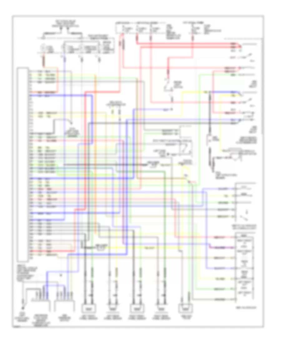
Anti-Lock Brake Wiring Diagram, A/T for Saab 9000 CSE 1995
List of elements for Anti-Lock Brake Wiring Diagram, A/T for Saab 9000 CSE 1995:
- (left rear side of engine compartment)
- 721a
- 723a
- 725a
- 727a
- 960b
- Abs control module
- Abs diode
- Abs fuse box (behind brake fluid reservoir)
- Abs main relay
- Abs pump relay
- Abs valve block
- Anti lock indicator
- Brake light switch
- Data link connector
- Fuse 1 30a
- Fuse 15a
- Fuse 2 30a
- Fuse 3 10a
- Fuse box (behind glove box)
- G104 (left structural member)
- Hot at all times
- Hot in run
- Hot in run, bulb test or start (from ignition switch)
- Hydraulic pump motor
- Left front in
- Left front out
- Left front wheel sensor
- Left rear in
- Left rear out
- Left rear wheel sensor
- Main instrument display panel
- Nca
- Pedal position sensor (on vacuum servo, mounted on bulkhead)
- Red
- Right front in
- Right front out
- Right front wheel sensor
- Right rear in
- Right rear out
- Right rear wheel sensor
- Tcs control module (under left front seat)
Anti-Lock Brake Wiring Diagram, M/T for Saab 9000 CSE 1995
List of elements for Anti-Lock Brake Wiring Diagram, M/T for Saab 9000 CSE 1995:
- (left side of i/p) g202
- 720b
- 721a
- 723a
- 725a
- 727a
- 750a
- 960b
- Abs brake fluid level sensor (in brake fluid reservoir)
- Abs diode
- Abs fuse box (behind brake fluid reservoir)
- Abs main relay
- Abs main valve
- Abs pressure switch
- Abs pump relay
- Abs valve block
- Abs-tc control module (left rear side of engine compartment, on battery tray)
- Abs-tc valve block (on hydraulic unit)
- Abs/tcs warning lamp
- Brake fluid level warning lamp
- Brake light switch
- Edu data link connector
- Ets throttle control module
- Fuse 1 30a
- Fuse 15a
- Fuse 2 30a
- Fuse 3 10a
- Fuse box (behind glove box)
- G104 (left side structural member)
- G104 (left structural member)
- Hot at all times
- Hot in run
- Hot in run, bulb test or start (from ignition switch)
- Hydraulic pump motor
- Left front in
- Left front out
- Left front wheel sensor
- Left rear wheel sensor
- Main instrument display panel
- Nca
- Rear in
- Rear out
- Red
- Right front in
- Right front out
- Right front wheel sensor
- Right rear wheel sensor
- Tcs indic. lamp
- Tcs on/ off switch
- Tcs warning lamp
3.0L
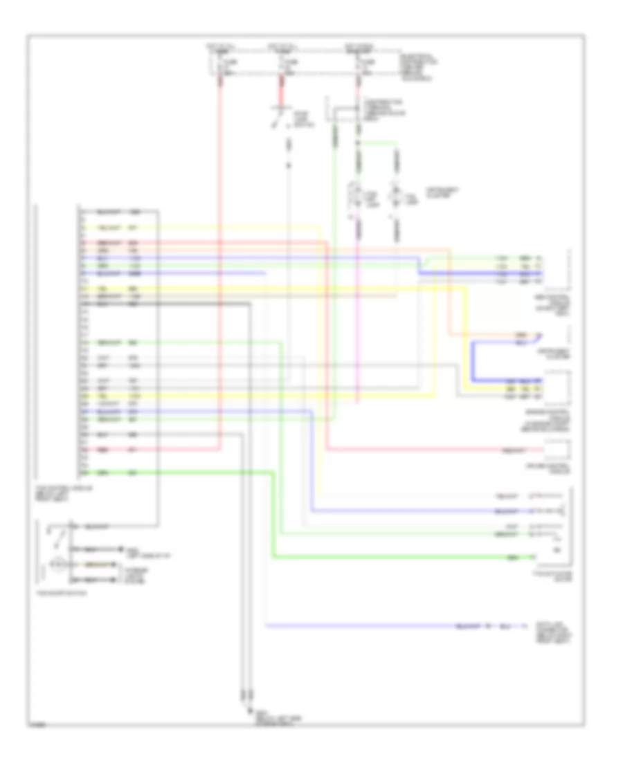
3.0L, Traction Control Wiring Diagram for Saab 9000 CSE 1995
List of elements for 3.0L, Traction Control Wiring Diagram for Saab 9000 CSE 1995:
- 896b
- Abs control module (on battery tray)
- Cruise control module
- Data link connector (below right front seat)
- Distribution terminal (behind glove box)
- Electrical distribution center (behind glove box)
- Engine control module (in engine compt behind bulkhead)
- Fuse 10a
- Fuse 15a
- Fuse 25a
- G202 (left side of i/p)
- G304 (below left side of rear seat)
- Hot at all times
- Hot in run or start
- Instrument cluster
- Interior lights system
- Red
- Stop lamp switch
- Tcs control module (below left front seat)
- Tcs lamp
- Tcs off lamp
- Tcs on/off switch
- Tts actuator motor
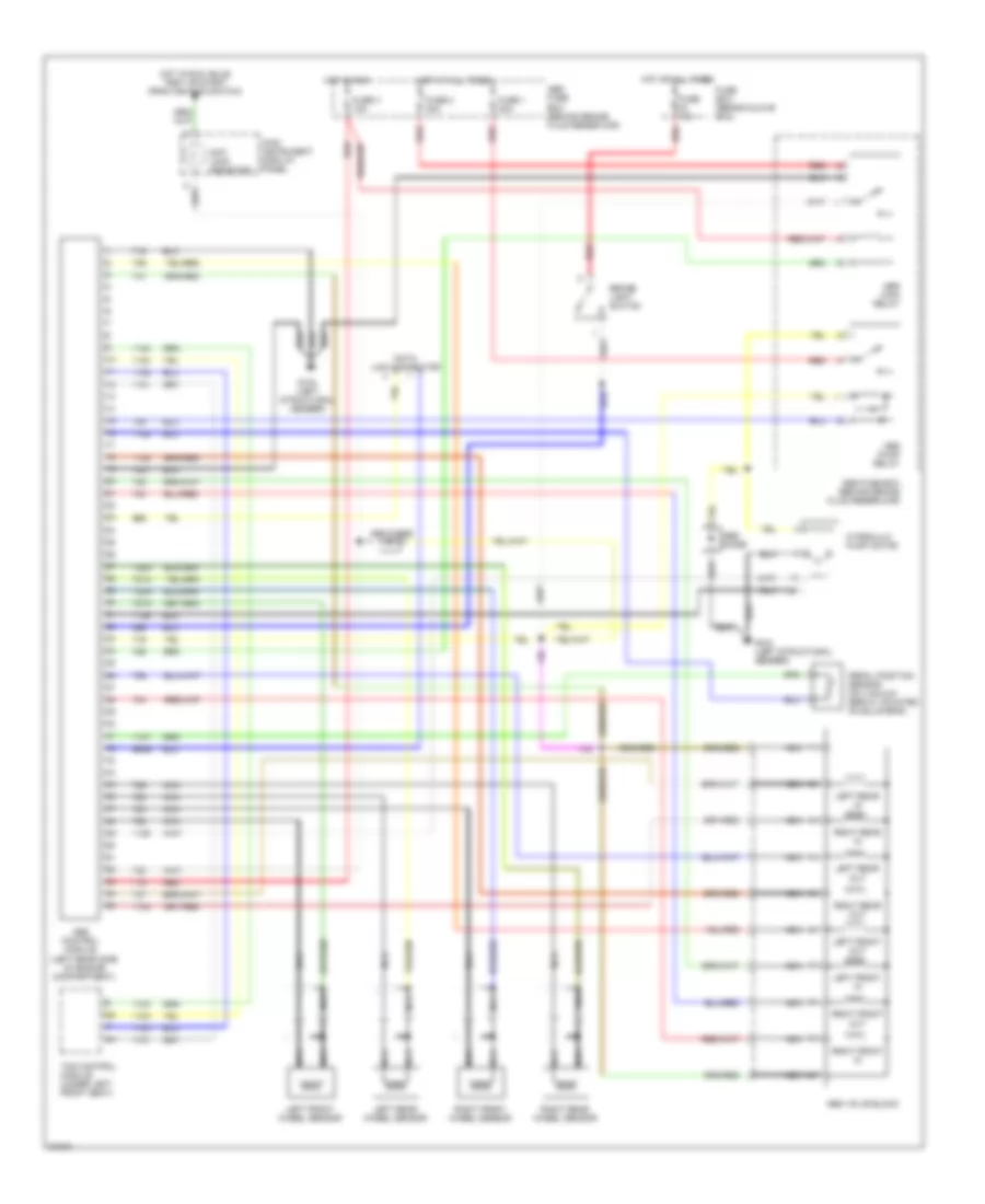
Anti-Lock Brake Wiring Diagram, A/T for Saab 9000 CSE 1995
List of elements for Anti-Lock Brake Wiring Diagram, A/T for Saab 9000 CSE 1995:
- (left rear side of engine compartment)
- 721a
- 723a
- 725a
- 727a
- 960b
- Abs control module
- Abs diode
- Abs fuse box (behind brake fluid reservoir)
- Abs main relay
- Abs pump relay
- Abs valve block
- Anti lock indicator
- Brake light switch
- Data link connector
- Fuse 1 30a
- Fuse 15a
- Fuse 2 30a
- Fuse 3 10a
- Fuse box (behind glove box)
- G104 (left structural member)
- Hot at all times
- Hot in run
- Hot in run, bulb test or start (from ignition switch)
- Hydraulic pump motor
- Left front in
- Left front out
- Left front wheel sensor
- Left rear in
- Left rear out
- Left rear wheel sensor
- Main instrument display panel
- Nca
- Pedal position sensor (on vacuum servo, mounted on bulkhead)
- Red
- Right front in
- Right front out
- Right front wheel sensor
- Right rear in
- Right rear out
- Right rear wheel sensor
- Tcs control module (under left front seat)
Anti-Lock Brake Wiring Diagram, M/T for Saab 9000 CSE 1995
List of elements for Anti-Lock Brake Wiring Diagram, M/T for Saab 9000 CSE 1995:
- (left side of i/p) g202
- 720b
- 721a
- 723a
- 725a
- 727a
- 750a
- 960b
- Abs brake fluid level sensor (in brake fluid reservoir)
- Abs diode
- Abs fuse box (behind brake fluid reservoir)
- Abs main relay
- Abs main valve
- Abs pressure switch
- Abs pump relay
- Abs valve block
- Abs-tc control module (left rear side of engine compartment, on battery tray)
- Abs-tc valve block (on hydraulic unit)
- Abs/tcs warning lamp
- Brake fluid level warning lamp
- Brake light switch
- Edu data link connector
- Ets throttle control module
- Fuse 1 30a
- Fuse 15a
- Fuse 2 30a
- Fuse 3 10a
- Fuse box (behind glove box)
- G104 (left side structural member)
- G104 (left structural member)
- Hot at all times
- Hot in run
- Hot in run, bulb test or start (from ignition switch)
- Hydraulic pump motor
- Left front in
- Left front out
- Left front wheel sensor
- Left rear wheel sensor
- Main instrument display panel
- Nca
- Rear in
- Rear out
- Red
- Right front in
- Right front out
- Right front wheel sensor
- Right rear wheel sensor
- Tcs indic. lamp
- Tcs on/ off switch
- Tcs warning lamp

 Čeština
 Dansk
Dansk Deutsch
 Ελληνικά
 English
 English
 Español
 Suomi
Suomi Français
 Français
 עברית
עברית Hrvatski
 Magyar
 日本語
日本語 한국어
한국어 Nederlands
 Polski
 Português
 Português
 Română
 Русский
 Slovenčina
 Slovenščina
 Svenska
 Türkçe
 中文 (中国)