CRUISE CONTROL
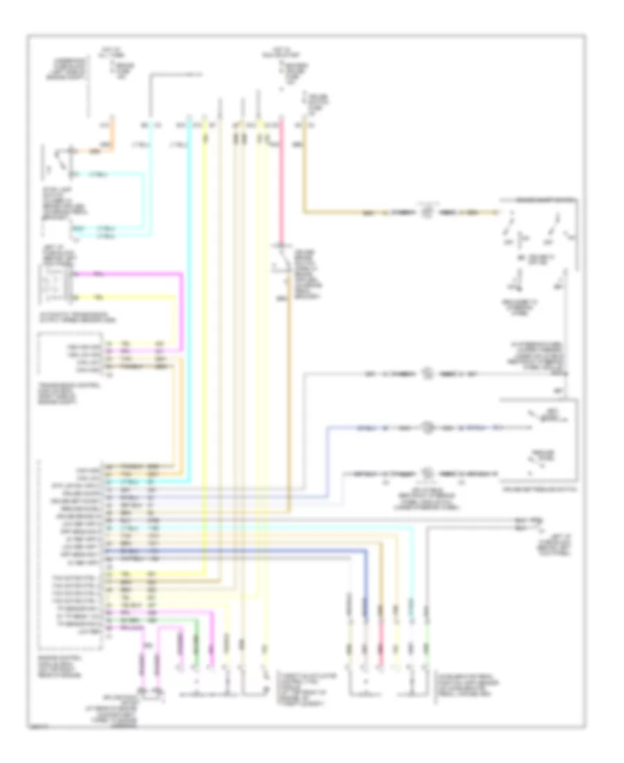
Cruise Control Wiring Diagram for Saturn L300 2005
List of elements for Cruise Control Wiring Diagram for Saturn L300 2005:
- (in steering wheel jumper harness, under inflatable restraint steering wheel module) s202
- 5v ref app 2
- 5v ref app1
- 5v tp sens 1 & 2
- A10
- Accelerator pedal position (app) sensor (on accelerator pedal linkage arm)
- All times
- App sens sig 1
- App sens sig 2
- Automatic transmission output speed sensor (oss)
- B10
- Bcm/ecm/ cruise fuse 10a
- Brake fuse 15a
- Can high
- Can low
- Cruise brake in
- Cruise on/off
- Cruise on/off switch
- Cruise set/coast
- Cruise set/resume switch
- Cruise switch fuse 2a
- Cruise w/ off ind
- D10
- D12
- E12
- Engine control module (ecm) (on top right rear of engine)
- F10
- Grounded to steering wheel
- Hot at
- Hot in run or start
- Inflatable restraint steering wheel module coil (under steering wheel)
- Left i/p fuse block (behind left kick panel)
- Low ref
- Low ref app 1
- Low ref app 2
- Nca
- Off
- Pnk
- Resume/ accel
- Resume/accel
- Set/ coast
- Splice pack sp105 (at rear of engine compartment, taped to engine harness)
- Stp lmp sw input
- Tac motor ctrl 1
- Tac motor ctrl 2
- Tan
- Throttle actuator control (tac) module (at top front of engine, on throttle body)
- Tp sensor sig 1
- Tp sensor sig 2
- Transmission control module (ecm) (right side of engine compt)
- Underhood fuse block (left side of engine compt)
- Vss high sig
- Vss low sig
 Čeština
 Dansk
Dansk Deutsch
 Ελληνικά
 English
 English
 Español
 Suomi
Suomi Français
 Français
 עברית
עברית Hrvatski
 Magyar
 日本語
日本語 한국어
한국어 Nederlands
 Polski
 Português
 Português
 Română
 Русский
 Slovenčina
 Slovenščina
 Svenska
 Türkçe
 中文 (中国)
 Italiano