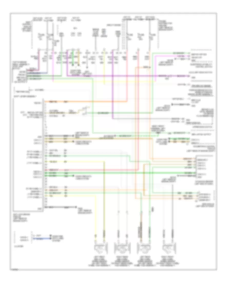
ANTI-LOCK BRAKES
Anti-lock Brakes Wiring Diagram for Fiat 500 Sport 2014
List of elements for Anti-lock Brakes Wiring Diagram for Fiat 500 Sport 2014:
- (a/t)
- (body front harness, left side of dash) s009
- (left rear of engine compt) g005
- (m/t)
- (top of brake pedal assembly) stop lamp switch
- A/t
- A111
- A921
- Anti-lock brake module (left rear of engine compt)
- Auxiliary bank switch
- B(+)
- B134
- B20
- B25
- Body control module (left end of dash)
- Brake fluid level sensor (on brake fluid reservoir)
- Brake fluid level signal
- Brk flud lvl sw
- Brk lmp sw output
- Brk sig 2
- Brk sig 2 brk lmp sw output
- Can b (+)
- Can b (-)
- Can bus (+)
- Can bus (-)
- Can c (+)
- Can c (-)
- Circuit board
- Cluster
- Computer data lines system
- D64
- D65
- Dynamics sensor (left end of dash)
- Electronic stability control switch
- Eps module (left end of dash)
- Esp sw off sig
- Esp sw off sig trs park sig
- Exterior lights system
- Fsd b (+)
- Fsd b(+)
- Fuse 10a
- Fuse 20a
- Fuse 40a
- Fuse 5a
- G005 (left rear of engine compt)
- G010a (left rear of engine compt)
- G010b (left rear of engine compt)
- G021 (left kick panel)
- Gnd
- Hot at all times
- Hot in on or start
- I008a
- I028
- Ign rs
- Ign sw o/p
- L56
- Left front abs wheel speed sensor (on left front wheel hub assembly)
- Left rear abs wheel speed sensor (on left rear wheel hub assembly)
- Lt ft wheel (+)
- Lt ft wheel (-)
- Lt rr wheel (+)
- Lt rr wheel (-)
- M/t
- Parking brake switch (base of parking brake lever assembly)
- Perf mode sig
- Power distribution center (left rear of engine compt)
- Powertrain control module (left rear of engine compt)
- Prk brk sw sense
- Right front abs wheel speed sensor (on right front wheel hub assembly)
- Right rear abs wheel speed sensor (on right rear wheel hub assembly)
- Rt ft wheel (+)
- Rt ft wheel (-)
- Rt rr wheel (+)
- Rt rr wheel (-)
- S026
- S52
- Sens sply
- Shift lever assembly
- Snsr sply
- T824 (or b47)
- Trs park sig
- Upper bank switch
- Z406
- Z905
- Z921
 Čeština
 Dansk
Dansk Deutsch
 Ελληνικά
 English
 English
 Español
 Suomi
Suomi Français
 Français
 עברית
עברית Hrvatski
 Magyar
 日本語
日本語 한국어
한국어 Nederlands
 Polski
 Português
 Português
 Română
 Русский
 Slovenčina
 Slovenščina
 Svenska
 Türkçe
 中文 (中国)
 Italiano