ANTI-LOCK BRAKES
Anti-lock Brake Wiring Diagrams for Nissan Pathfinder LE 1998
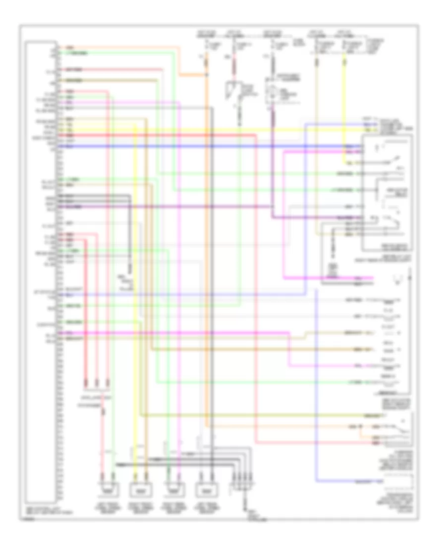
List of elements for Anti-lock Brake Wiring Diagrams for Nissan Pathfinder LE 1998:
- (right "a" pillar)
- 2wd
- 4wd
- Abs actuator (right rear of engine compt)
- Abs control unit (below center of dash)
- Abs motor relay
- Abs relay unit (right rear of engine compt)
- Abs solenoid valve relay
- Abs warning lamp
- Bls
- Data link connector (lower left side
- Diag l
- Fl in
- Fl out
- Fl ss
- Fl ss gnd
- Fr in
- Fr out
- Fr ss
- Fr ss gnd
- Fuse 14 10a
- Fuse 7 7.5a
- Fuse 8 10a
- Fuse block
- Fusible link & fuse box
- Fusible link c 40a
- Fusible link d 40a
- G sensor (all qx4 and (4wd pathfinder) (below rear of center console)
- G switch
- G-sw check
- G200 (left kick panel)
- G901
- G901 (right "a" pillar)
- Gnd
- Gnd1
- Gnd2
- Hot at all times
- Hot in on or start
- Instrument cluster
- Left front wheel speed sensor
- Left rear wheel speed sensor
- Nca
- Of dash)
- Pathfinder
- Qx4
- Rear in
- Rear out
- Red
- Right front wheel speed sensor
- Right rear wheel speed sensor
- Rl in
- Rl out
- Rl ss
- Rl ss gnd
- Rr ss
- Rr ss gnd
- Rxd
- Sila
- St status
- Stop lamp switch
- Transmission control module (behind dash, left of steering column)
- Txd
 Čeština
 Dansk
Dansk Deutsch
 Ελληνικά
 English
 English
 Español
 Suomi
Suomi Français
 Français
 עברית
עברית Hrvatski
 Magyar
 日本語
日本語 한국어
한국어 Nederlands
 Polski
 Português
 Português
 Română
 Русский
 Slovenčina
 Slovenščina
 Svenska
 Türkçe
 中文 (中国)
 Italiano