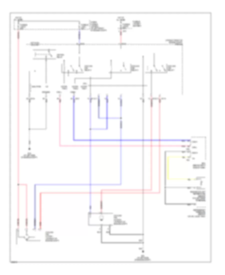
COOLING FAN
Cooling Fan Wiring Diagram for Nissan Maxima SL 2007
List of elements for Cooling Fan Wiring Diagram for Nissan Maxima SL 2007:
- (at right front of engine compt) ipdm e/r
- +ig
- Can-h
- Can-l
- Cooling fan motor 1 (at front of engine compt)
- Cooling fan motor 2 (at front of engine compt)
- Cooling fan relay 1
- Cooling fan relay 2
- Cooling fan relay 3
- Cpu
- E10
- E118
- E120
- E121
- E123
- E124
- E15 (at left side of engine compt)
- Ecm (behind right side of dash)
- Engine coolant temperature sensor (on left rear of engine)
- F54
- Fuse & fusible link box (at left front of engine compt)
- Fusible link b 80a
- Fusible link box (battery)
- Fusible link k 40a
- Fusible link l 40a
- Gnd (pwr)
- Gnd (sig)
- Gnd-a
- Hot at all times
- Hot in on or start
- Ignition relay
- M82
- Motor fan-1
- Motor fan-2
- Motor fan-3
- Pnk
- Red
- Refrigerant pressure sensor (on a/c liquid tank)
 Čeština
 Dansk
Dansk Deutsch
 Ελληνικά
 English
 English
 Español
 Suomi
Suomi Français
 Français
 עברית
עברית Hrvatski
 Magyar
 日本語
日本語 한국어
한국어 Nederlands
 Polski
 Português
 Português
 Română
 Русский
 Slovenčina
 Slovenščina
 Svenska
 Türkçe
 中文 (中国)
 Italiano