CRUISE CONTROL
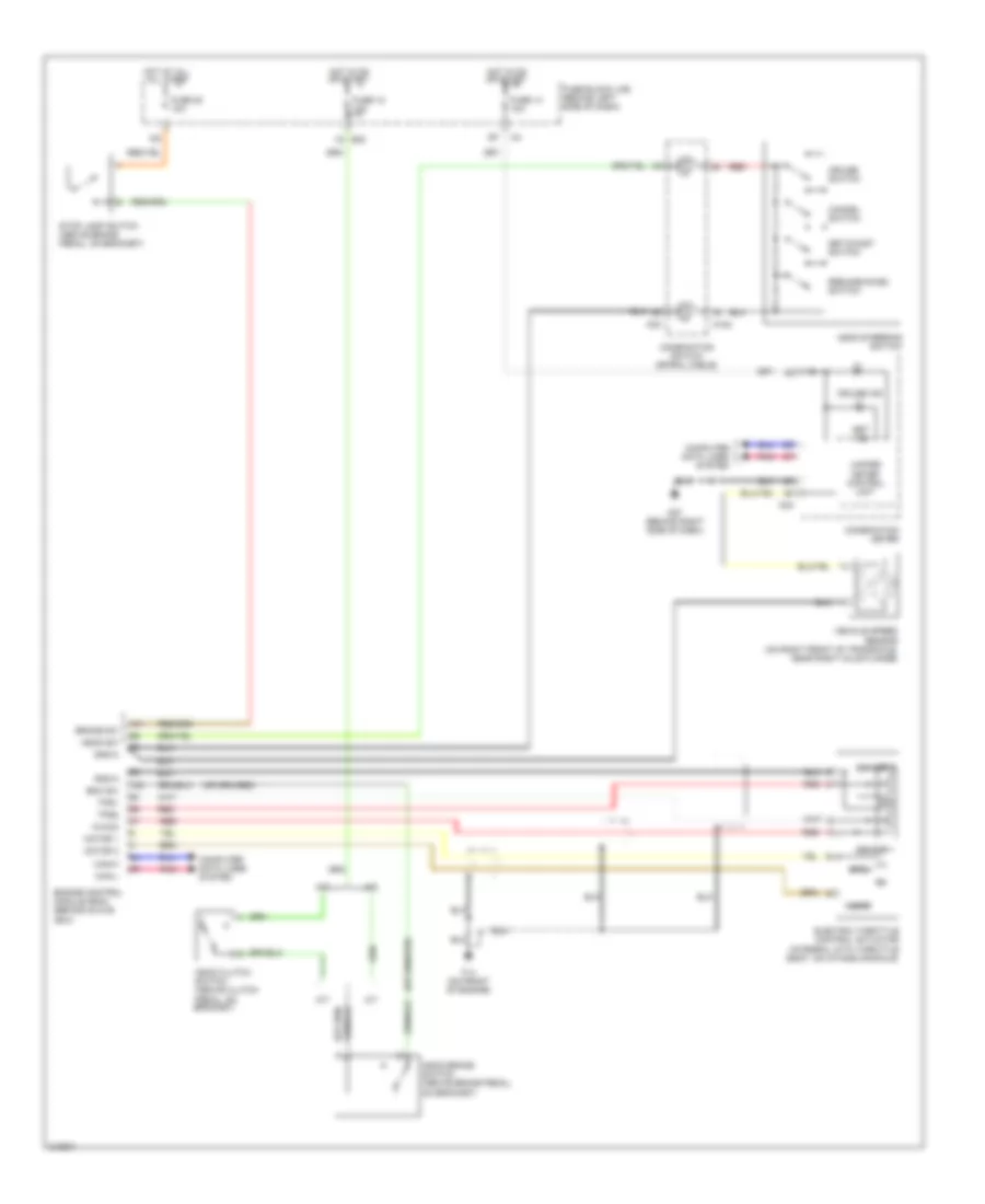
Cruise Control Wiring Diagram for Nissan Altima SE-R 2006
List of elements for Cruise Control Wiring Diagram for Nissan Altima SE-R 2006:
- A/t
- Ascd brake switch (above brake pedal, on bracket)
- Ascd clutch switch (above clutch pedal, on bracket)
- Ascd steering switch
- Ascd sw
- Avcc2
- Bnc sw
- Brake sw
- Can-h
- Can-l
- Cancel switch
- Close
- Combination meter
- Combination switch (spiral cable)
- Computer data lines system
- Cruise ind
- Cruise switch
- E30
- Electric throttle control actuator (integral with throttle body, on intake manifold)
- Engine control module (ecm) (behind glove box)
- F14 (on front of engine)
- Fuse 12 10a
- Fuse 14 10a
- Fuse 20 10a
- Fuse block (j/b) (behind left side of dash)
- Gnd-a
- Hot at all all times
- Hot in on or start
- M/t
- M102
- M24
- M30
- M57 (behind right side of dash)
- Motor 1
- Motor 2
- Open
- Pnk
- Red
- Resume/accel switch
- Sensor 1
- Sensor 2
- Set ind
- Set/coast switch
- Stop lamp switch (above brake pedal, on bracket)
- Tps1
- Tps2
- Unified meter control unit
- Vehicle speed sensor (on right front of transaxle, near right axle flange)
 Čeština
 Dansk
Dansk Deutsch
 Ελληνικά
 English
 English
 Español
 Suomi
Suomi Français
 Français
 עברית
עברית Hrvatski
 Magyar
 日本語
日本語 한국어
한국어 Nederlands
 Polski
 Português
 Português
 Română
 Русский
 Slovenčina
 Slovenščina
 Svenska
 Türkçe
 中文 (中国)
 Italiano