CRUISE CONTROL
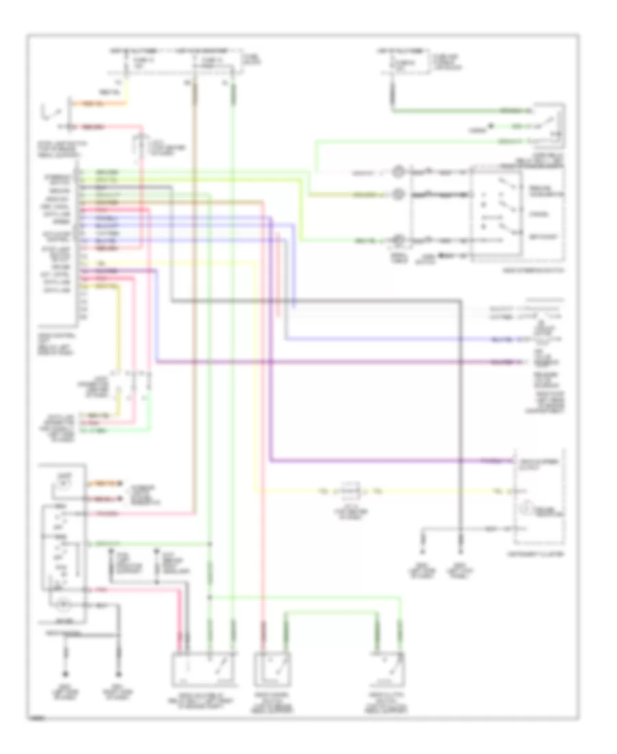
Cruise Control Wiring Diagram, A/T for Nissan Maxima SE 1996
 https://portal-diagnostov.com/license.html
Automotive Electricians Portal FZCO
Automotive Electricians Portal FZCO
https://portal-diagnostov.com/license.html
https://portal-diagnostov.com/license.html
Automotive Electricians Portal FZCO
Automotive Electricians Portal FZCO
List of elements for Cruise Control Wiring Diagram, A/T for Nissan Maxima SE 1996:
- A/t control unit (left kick panel)
- Act. cntrl
- Actuator control
- Air valve solenoid
- Ascd cancel switch (top of brake pedal support)
- Ascd control unit (below left side of dash)
- Ascd hold relay (relay box 1, left front of engine compt)
- Ascd pump (left rear of engine compartment)
- Ascd steering switch
- Ascd sw.
- Ascd switch
- Cancel
- Crs. cancl
- Cruise
- Cruise indicator
- Cruise signal
- Data line
- Data link connector for consult (left side of dash)
- Fuse 10 15a
- Fuse 12 7.5a
- Fuse 17 10a
- Fuse 64 10a
- Fuse and fusible link block
- Fuse block
- G105 (rear of right front fender)
- G107 (behind right headlamp)
- G125 (front of engine)
- G201 (right side of dash)
- G202 (left side of dash)
- Ground
- Horn relay (relay box 1, left front of engine compt)
- Horn switch
- Horns
- Hot at all times
- Hot in on or start
- Illum.
- Inhibitor relay (relay box 1, left front of engine compartment)
- Inhibitor switch (left side of transmission)
- Instrument cluster
- Interior lights system (rheostat)
- J/c 14 (top center of dash)
- J/c 3 (top center of dash)
- Joint connector (center of dash)
- Nca
- Od cut signal
- Off
- On ind.
- Pnk
- Release valve solenoid
- Resume/ accelerate
- Set/coast
- Speed
- Spiral cable
- Steering switch
- Stop lamp switch (top of brake pedal support)
- Stop lamp switch od cut
- Theft warning relay 2 (relay box-2, right front fender)
- Vacuum motor
- Vehicle speed output
Cruise Control Wiring Diagram, M/T for Nissan Maxima SE 1996
List of elements for Cruise Control Wiring Diagram, M/T for Nissan Maxima SE 1996:
- Act. cntrl
- Actuator control
- Air valve solenoid
- Ascd cancel switch (top of brake pedal support)
- Ascd clutch switch (top of clutch pedal support)
- Ascd control unit (below left side of dash)
- Ascd hold relay (relay box 1, left front of engine compt)
- Ascd pump (left rear of engine compartment)
- Ascd steering switch
- Ascd sw.
- Ascd switch
- Cancel
- Crs. cancl
- Cruise
- Cruise indicator
- Data line
- Data link connector for consult (left side of dash)
- Fuse 10 15a
- Fuse 12 7.5a
- Fuse 64 10a
- Fuse and fusible link block
- Fuse block
- G107 (behind right headlamp)
- G108 (left radiator support)
- G201 (right side of dash)
- G202 (left side of dash)
- G203 (left kick panel)
- Ground
- Horn relay (relay box 1, left front of engine compt)
- Horn switch
- Horns
- Hot at all times
- Hot in on or start
- Illum.
- Instrument cluster
- Interior lights system (rheostat)
- J/c 14 (top center of dash)
- J/c 3 (top center of dash)
- Joint connector (center of dash)
- Nca
- Off
- On ind.
- Pnk
- Release valve solenoid
- Resume/ accelerate
- Set/coast
- Speed
- Spiral cable
- Steering switch
- Stop lamp switch (top of brake pedal support)
- Stop lamp switch od cut
- Vacuum motor
- Vehicle speed output

 Čeština
 Dansk
Dansk Deutsch
 Ελληνικά
 English
 English
 Español
 Suomi
Suomi Français
 Français
 עברית
עברית Hrvatski
 Magyar
 日本語
日本語 한국어
한국어 Nederlands
 Polski
 Português
 Português
 Română
 Русский
 Slovenčina
 Slovenščina
 Svenska
 Türkçe
 中文 (中国)