STARTING/CHARGING
Charging Wiring Diagram for Mitsubishi Eclipse Spyder GS 2010
 https://portal-diagnostov.com/license.html
Automotive Electricians Portal FZCO
Automotive Electricians Portal FZCO
https://portal-diagnostov.com/license.html
https://portal-diagnostov.com/license.html
Automotive Electricians Portal FZCO
Automotive Electricians Portal FZCO
List of elements for Charging Wiring Diagram for Mitsubishi Eclipse Spyder GS 2010:
- 120a
- 40a
- 7.5a
- A15
- Acc
- B22
- Battery
- C202
- C215
- C24
- Combination meter
- Computer data lines system
- Cpu
- Engine compartment relay box (left side of engine compt)
- Engine control module (m/t) powertrain control module (a/t) (left side of engine compt, forward of relay box)
- Fuse 13
- Fuse 2 7.5a
- Fusible link 27 (on battery terminal)
- Fusible link 4
- G11 (2.4l: lower rear of engine) (3.8l: rear of engine)
- G15 (near left front shock tower)
- Generator
- Generator malfunction light ind
- Ignition switch
- Joint connector 2 (behind left side of dash)
- Junction block (under left end of dash)
- Lock
- Power distribution system
- Red
- Run
- Start
- Starting circuit
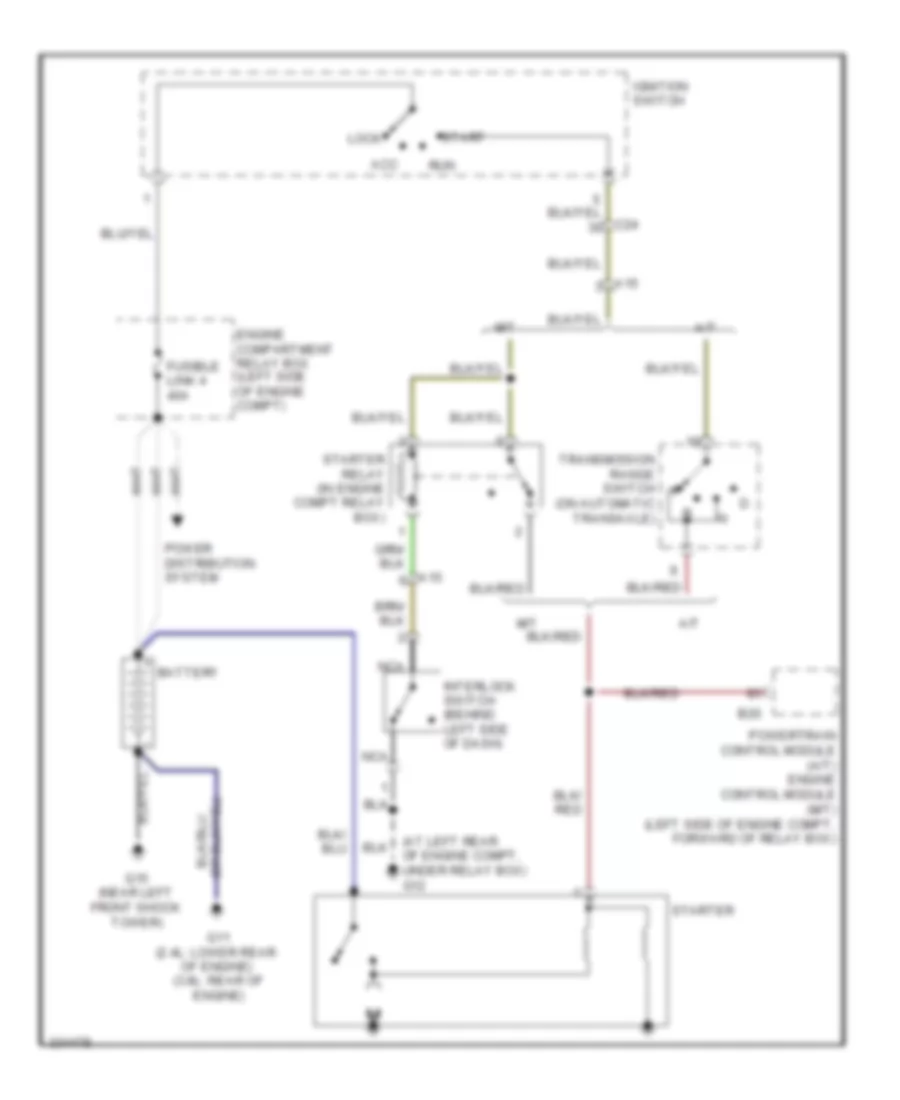
Starting Wiring Diagram for Mitsubishi Eclipse Spyder GS 2010
List of elements for Starting Wiring Diagram for Mitsubishi Eclipse Spyder GS 2010:
- (at left rear of engine compt, under relay box) g12
- A/t
- A15
- Acc
- B20
- Battery
- C24
- Engine compartment relay box (left side of engine compt)
- Fusible link 4 40a
- G11 (2.4l: lower rear of engine) (3.8l: rear of engine)
- G15 (near left front shock tower)
- Ignition switch
- Interlock switch (behind left side of dash)
- Lock
- M/t
- Nca
- Power distribution system
- Powertrain control module (a/t) engine control module (m/t) (left side of engine compt, forward of relay box)
- Run
- Start
- Starter
- Starter relay (in engine compt relay box)
- Transmission range switch (on automatic transaxle)

 Čeština
 Dansk
Dansk Deutsch
 Ελληνικά
 English
 English
 Español
 Suomi
Suomi Français
 Français
 עברית
עברית Hrvatski
 Magyar
 日本語
日本語 한국어
한국어 Nederlands
 Polski
 Português
 Português
 Română
 Русский
 Slovenčina
 Slovenščina
 Svenska
 Türkçe
 中文 (中国)