TRANSMISSION
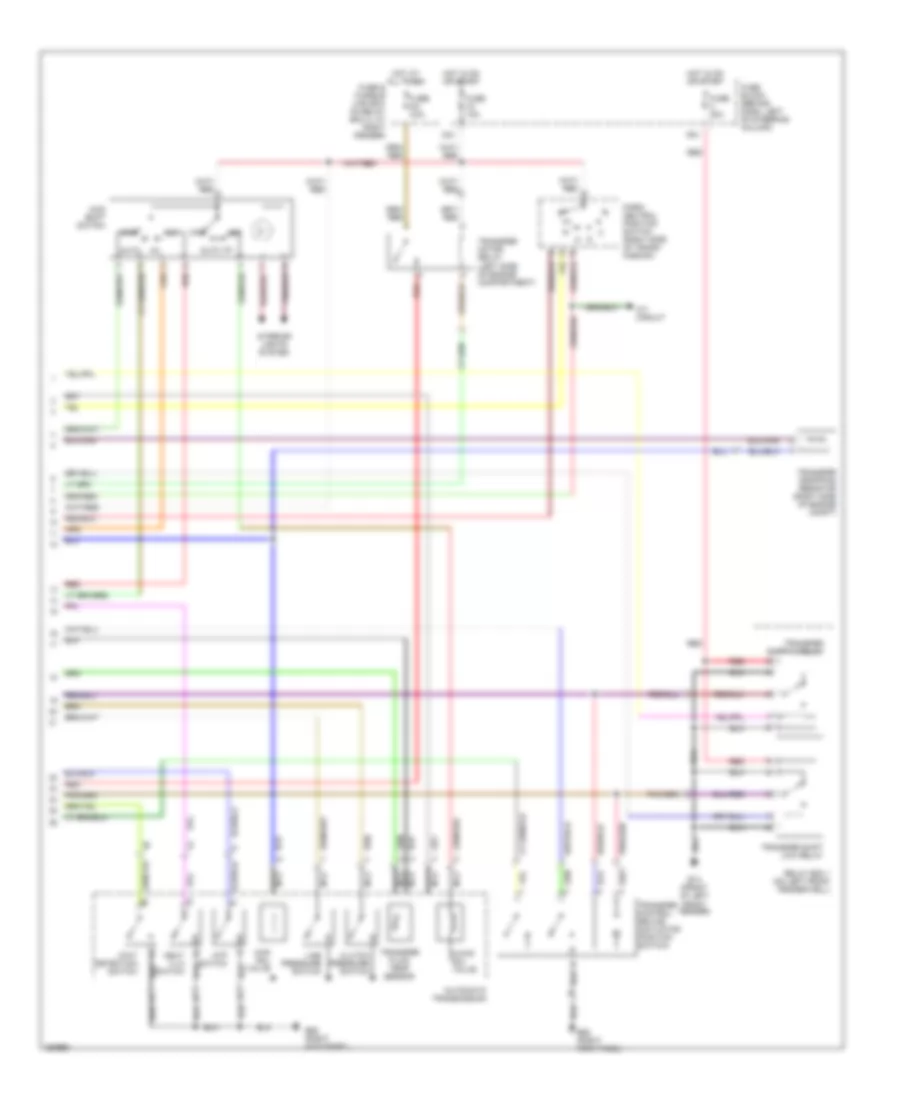
4WD Wiring Diagram (1 of 2) for Nissan Pathfinder SE 2001
 https://portal-diagnostov.com/license.html
Automotive Electricians Portal FZCO
Automotive Electricians Portal FZCO
https://portal-diagnostov.com/license.html
https://portal-diagnostov.com/license.html
Automotive Electricians Portal FZCO
Automotive Electricians Portal FZCO
List of elements for 4WD Wiring Diagram (1 of 2) for Nissan Pathfinder SE 2001:
- 10u
- 11u
- 17u
- 2-4wd
- 2wd l
- 2wd lp
- 2wd r
- 2wd sw
- 4h sw
- 4l sw
- 4lo
- 4lo ind
- 4wd d/r
- 4wd l
- 4wd lp
- 4wd r
- 4wd sol
- 4wd temp
- 4wd warn ind
- Abs sig
- Actr sw1
- Actr sw2
- Anti-lock brakes
- Atp sw
- Atp warn ind
- Auto lp
- Auto sw
- Avcc
- B55 (right kick panel)
- Closed throttle
- Cnslt rx
- Cnslt tx
- Combination meter
- Cps
- Data link connector (on lower dash panel, left side of steering column)
- Ecm (behind center of dash)
- F20 (left front of engine)
- F43 (left front of engine)
- Front revolution sensor (transfer) (left of transfer case)
- Full sw
- Fuse 10a
- Fuse 7.5a
- Fuse block (behind dash, left of steering column)
- Gnd
- Gnd-a
- Hot at all times
- Hot in on or start
- Idle sw
- J/c (left end of dash)
- Lock
- Lock lp
- Lps
- M4 (left side of dash)
- M77 (left kick panel)
- Mem b/u
- Mot/mon
- Mot/rly
- N-4lo
- N-sw
- Nca
- P-sw
- Pnk
- R-sw
- Red
- Rly ctrl
- Sens gnd
- Sens pwr
- Tacho
- Th sens
- Throttle position sensor (on throttle body)
- Throttle position switch (integral to throttle position sensor)
- Transfer control unit (behind lower center dash panel)
- Transfer motor (left rear of transfer case)
- Transmission control module (behind dash, left of steering column)
- Tvo1
- Tvoo
- Unified meter cntrl unit
- Vign
- Vsp in
- Vsp out
- Wait sw
- Wot
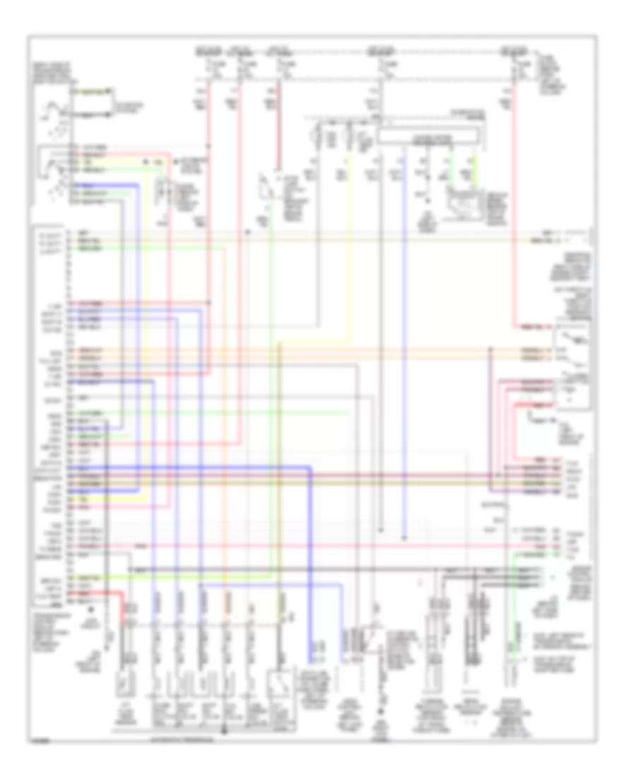
4WD Wiring Diagram (2 of 2) for Nissan Pathfinder SE 2001
List of elements for 4WD Wiring Diagram (2 of 2) for Nissan Pathfinder SE 2001:
- 2-4wd sol valve
- 24u
- 2wd
- 48u
- 4lo
- 4wd shift switch
- 4wd sol valve
- A/t circuit
- Atp switch
- Auto
- Automatic transmission
- B55 (right kick panel)
- Clutch pressure switch
- E13 (front of left front fender)
- Fuse & fusible link box (in relay box 2, at right fender)
- Fuse 10a
- Fuse 20a
- Fuse block (behind dash, left of steering column)
- Hot at all times
- Hot in on or start
- Interior lights system
- Line pressure switch
- Nca
- Neut 4 lo switch
- Park/ neutral position switch (right side of trans- mission)
- Red
- Relay box 1 (on left front fender well)
- Transfer control device (actuator position switch)
- Transfer dropping resistor (right side of engine compt)
- Transfer fluid temp sensor
- Transfer motor relay (left side of engine compartment)
- Transfer shift hi relay
- Transfer shift low relay
- Wait detection switch
A/T Wiring Diagram for Nissan Pathfinder SE 2001
List of elements for A/T Wiring Diagram for Nissan Pathfinder SE 2001:
- (behind center of dash)
- (on throttle body) throttle position sensor & switch
- (right side of transmission) park/neutral position switch
- 1-sw
- 10u
- 17u
- 2-sw
- 24u
- 2wd: left rear of transmission extension assembly
- 39u
- 4wd circuit
- 4wd: on top of transmission adapter case
- A/t device (overdrive control switch) (base of selector lever)
- A/t fluid temp ind
- A/t fluid temp sensor
- A/t fluid temp switch (4wd)
- Ascd
- Ascd control unit (behind
- Automatic transaxle
- Avcc
- B55 (right kick panel)
- B64
- Brk sw
- Closed throttle
- Combination meter
- D-sw
- Data in
- Data link connector (on lower dash panel, left of steering column)
- Data out
- Diode (behind left side of dash)
- Dropping resistor (right side of engine compt, near battery)
- Engine control module
- Engine coolant temperature sensor (rear of engine, on water outlet)
- Exterior lights system
- F20 (left front of engine)
- F43 (left front of engine)
- Fld temp
- Full sw
- Fuse 10a
- Fuse block (behind dash, left of steering column)
- Gnd
- Gnd-a
- Hot at all times
- Hot in on or start
- Idle
- J/c (behind left side of dash)
- Lan
- Left kick panel)
- Line press sol valve
- Lu duty
- M4 (left side of dash)
- Mem b/u
- Nca
- O/d ind
- O/d off ind
- Od sw
- Ov r/c
- Over- run clutch sol
- P/n-sw
- Pl duty
- Pnk
- R-sw
- Rear revolution sensor
- Red
- Sens gnd
- Sens pwr
- Shift a
- Shift b
- Shift sol valve a
- Shift sol valve b
- Starting system
- Stop lamp switch (on bracket, above brake pedal)
- Tacho
- Tcc sol valve
- Th sens
- Transmission control module (behind dash, left of steering column)
- Tss
- Turbine revolution sensor (top front of trans- mission case)
- Tv00
- Tv01
- Unified meter control unit
- V ign
- Vehicle speed sensor (top of trans- mission)
- Vsp
- Vsp in
- Vsp-2
- Vsp1
- Wot

 Čeština
 Dansk
Dansk Deutsch
 Ελληνικά
 English
 English
 Español
 Suomi
Suomi Français
 Français
 עברית
עברית Hrvatski
 Magyar
 日本語
日本語 한국어
한국어 Nederlands
 Polski
 Português
 Português
 Română
 Русский
 Slovenčina
 Slovenščina
 Svenska
 Türkçe
 中文 (中国)