ENGINE PERFORMANCE
2.3L
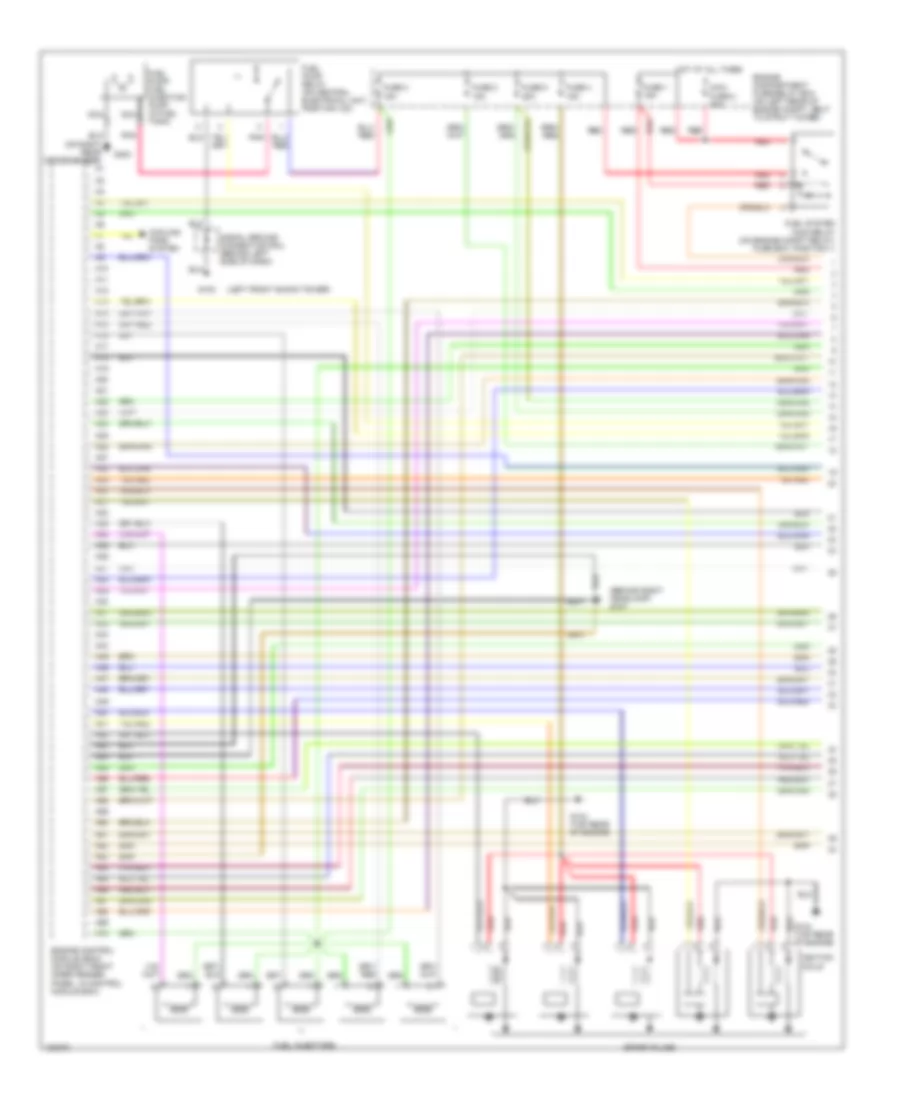
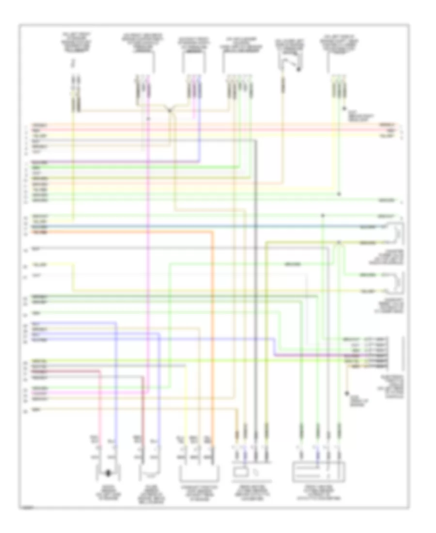
2.3L Turbo, Engine Performance Wiring Diagrams (1 of 3) for Volvo V70 R 2000
 https://portal-diagnostov.com/license.html
Automotive Electricians Portal FZCO
Automotive Electricians Portal FZCO
https://portal-diagnostov.com/license.html
https://portal-diagnostov.com/license.html
Automotive Electricians Portal FZCO
Automotive Electricians Portal FZCO
List of elements for 2.3L Turbo, Engine Performance Wiring Diagrams (1 of 3) for Volvo V70 R 2000:
- (behind right headlamp) g107
- (left front shock tower)
- (on right rear crossmember)
- A10
- A11
- A12
- A13
- A14
- A15
- A16
- A17
- A18
- A19
- A20
- A21
- A22
- A23
- A24
- A25
- A26
- A27
- A28
- A29
- A30
- A31
- A32
- A33
- A34
- A35
- A36
- A37
- A38
- A39
- A40
- A41
- A42
- A43
- A44
- A45
- A46
- A47
- A48
- A49
- A50
- A51
- A52
- A53
- A54
- A55
- A56
- A57
- A58
- A59
- A60
- A61
- A62
- A63
- A64
- A65
- A66
- A67
- A68
- A69
- A70
- Cooling fans system
- Engine compartment fuse/relay box (on left rear of engine compt, next to strut tower)
- Engine control module (ecm) (on right front inner fender panel, in control module box)
- Fuel injectors
- Fuel pump relay (on central electrical unit, position 103)
- Fuel pump/ fuel injection pump (in fuel tank)
- Fuel system main relay (on engine compt relay/ fuse box, position 1)
- Fuse 1 15a
- Fuse 2 15a
- Fuse 3 15a
- Fuse 4 15a
- Fuse 5 20a
- G102
- G134 (top rear of engine)
- G303
- Hot at all times
- Ignition coils
- Maxi fuse 8 60a
- Nca
- Pnk
- Red
- Signal ground connection rail (behind left side of dash)
- Spark plugs
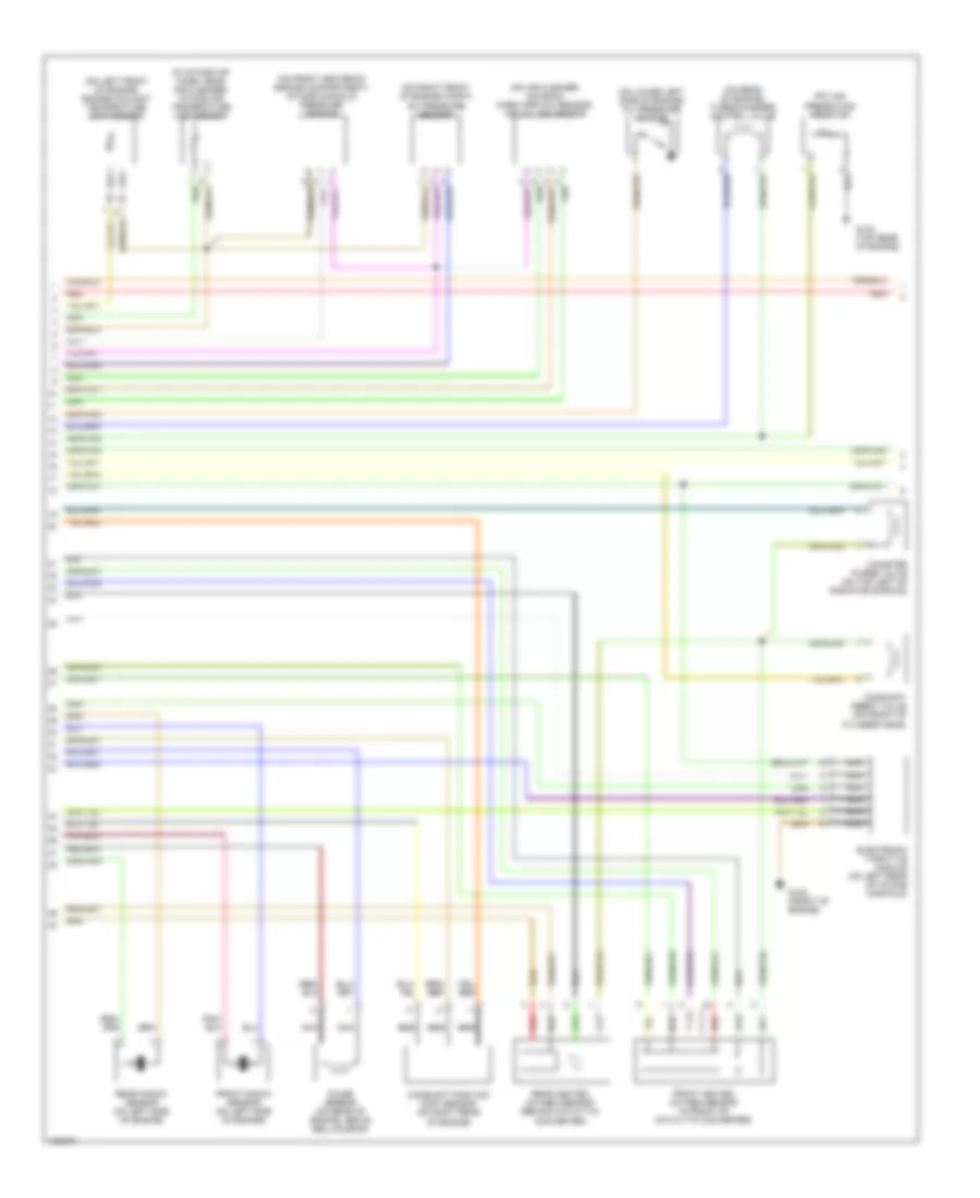
2.3L Turbo, Engine Performance Wiring Diagrams (2 of 3) for Volvo V70 R 2000
List of elements for 2.3L Turbo, Engine Performance Wiring Diagrams (2 of 3) for Volvo V70 R 2000:
- (in intake air hose, near air cleaner) intake air temperature (iat) sensor
- (on air cleaner housing) mass airflow sensor/ air volume sensor
- (on front center of engine compartment) intake manifold pressure sensor
- (on left front of engine) engine coolant temperature (ect) sensor
- (on lower left side of engine) oil pressure sensor
- (on rear of engine) turbocharger control valve
- (on right front of engine compt) a/c pressure sensor
- Camshaft position (cmp) sensor (on right rear of engine)
- Camshaft reset valve (on front of cylinder head)
- Canister purge valve (on top left of radiator shroud)
- Electronic throttle module (on left rear of intake manifold)
- Front heated oxygen sensor (in front of catalytic converter)
- Front knock sensor (on left side of engine)
- G125 (front of engine)
- G134 (top rear of engine)
- Nca
- Nca nca
- Ptc air preheating resistor
- Pulse sensor (on rear of engine, above bellhousing)
- Rear heated oxygen sensor (behind catalytic converter)
- Rear knock sensor (on left side of engine)
- Red
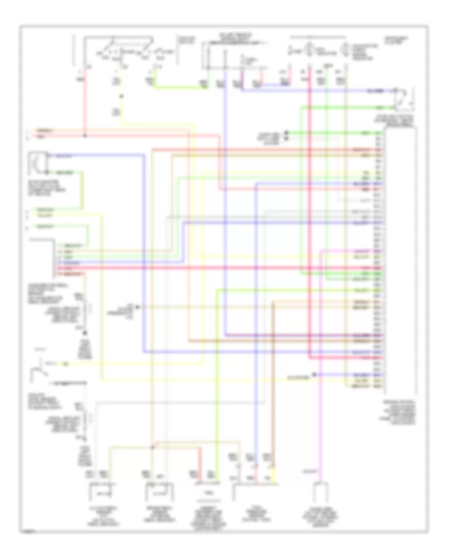
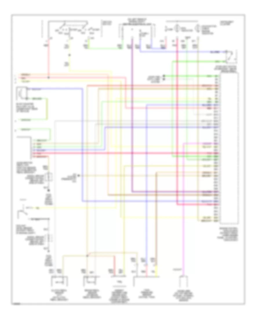
2.3L Turbo, Engine Performance Wiring Diagrams (3 of 3) for Volvo V70 R 2000
List of elements for 2.3L Turbo, Engine Performance Wiring Diagrams (3 of 3) for Volvo V70 R 2000:
- (on left rear of engine compt) central electrical unit
- A/c system
- A/c system (pressostat a/c)
- A18
- A26
- Acc
- Accelerator pedal (a/p) position sensor (on accelerator pedal bracket)
- Ambient temperature sensor (ecm) (in right front corner of engine compartment)
- B10
- B11
- B12
- B13
- B14
- B15
- B16
- B17
- B18
- B19
- B20
- B21
- B22
- B23
- B24
- B25
- B26
- B27
- B28
- B29
- B30
- B31
- B32
- B33
- B34
- B35
- B36
- B37
- B38
- B39
- B40
- B41
- B42
- B43
- B44
- B45
- B46
- Brake pedal sensor (on brake pedal bracket)
- Clutch pedal sensor (m/t) (on clutch pedal bracket)
- Computer data lines system
- Coolant level sensor (on right front of engine compt)
- Engine control module (ecm) (on right front inner fender panel, in control module box)
- Ets indicator
- Evap canister shut-off valve (under right rear of vehicle)
- Fuse
- Fuse 4 10a
- G102 (left front shock tower)
- Ignition switch
- Immobilizer (on top center of dash, integral with ecc sun sensor)
- Instrument cluster
- Malfunction check engine indicator
- Off
- Pnk
- Red
- Run
- Signal ground connection rail (behind left side of dash)
- Start
- Stoplight switch (on bracket, above brake pedal)
- Tank pressure sensor (on fuel tank)
- Temp
2.4L
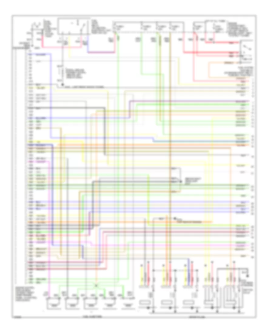
2.4L Turbo, Engine Performance Wiring Diagrams (1 of 3) for Volvo V70 R 2000
List of elements for 2.4L Turbo, Engine Performance Wiring Diagrams (1 of 3) for Volvo V70 R 2000:
- (behind right headlamp) g107
- (left front shock tower)
- (on right rear crossmember)
- A10
- A11
- A12
- A13
- A14
- A15
- A16
- A17
- A18
- A19
- A20
- A21
- A22
- A23
- A24
- A25
- A26
- A27
- A28
- A29
- A30
- A31
- A32
- A33
- A34
- A35
- A36
- A37
- A38
- A39
- A40
- A41
- A42
- A43
- A44
- A45
- A46
- A47
- A48
- A49
- A50
- A51
- A52
- A53
- A54
- A55
- A56
- A57
- A58
- A59
- A60
- A61
- A62
- A63
- A64
- A65
- A66
- A67
- A68
- A69
- A70
- Cooling fans system
- Engine compartment fuse/relay box (on left rear of engine compt, next to strut tower)
- Engine control module (ecm) (on right front inner fender panel, in control module box)
- Fuel injectors
- Fuel pump relay (on central electrical unit, position 103)
- Fuel pump/ fuel injection pump (in fuel tank)
- Fuel system main relay (on engine compt relay/ fuse box, position 1)
- Fuse 1 15a
- Fuse 2 15a
- Fuse 3 15a
- Fuse 4 15a
- Fuse 5 20a
- G102
- G134 (top rear of engine)
- G303
- Hot at all times
- Ignition coils
- Maxi fuse 8 60a
- Nca
- Pnk
- Red
- Signal ground connection rail (behind left side of dash)
- Spark plugs
2.4L Turbo, Engine Performance Wiring Diagrams (2 of 3) for Volvo V70 R 2000
List of elements for 2.4L Turbo, Engine Performance Wiring Diagrams (2 of 3) for Volvo V70 R 2000:
- (in intake air hose, near air cleaner) intake air temperature (iat) sensor
- (on air cleaner housing) mass airflow sensor/ air volume sensor
- (on front center of engine compartment) intake manifold pressure sensor
- (on left front of engine) engine coolant temperature (ect) sensor
- (on lower left side of engine) oil pressure sensor
- (on rear of engine) turbocharger control valve
- (on right front of engine compt) a/c pressure sensor
- Camshaft position (cmp) sensor (on right rear of engine)
- Camshaft reset valve (on front of cylinder head)
- Canister purge valve (on top left of radiator shroud)
- Electronic throttle module (on left rear of intake manifold)
- Front heated oxygen sensor (in front of catalytic converter)
- Front knock sensor (on left side of engine)
- G125 (front of engine)
- G134 (top rear of engine)
- Nca
- Nca nca
- Ptc air preheating resistor
- Pulse sensor (on rear of engine, above bellhousing)
- Rear heated oxygen sensor (behind catalytic converter)
- Rear knock sensor (on left side of engine)
- Red
2.4L Turbo, Engine Performance Wiring Diagrams (3 of 3) for Volvo V70 R 2000
List of elements for 2.4L Turbo, Engine Performance Wiring Diagrams (3 of 3) for Volvo V70 R 2000:
- (on left rear of engine compt) central electrical unit
- A/c system
- A/c system (pressostat a/c)
- A18
- A26
- Acc
- Accelerator pedal (a/p) position sensor (on accelerator pedal bracket)
- Ambient temperature sensor (ecm) (in right front corner of engine compartment)
- B10
- B11
- B12
- B13
- B14
- B15
- B16
- B17
- B18
- B19
- B20
- B21
- B22
- B23
- B24
- B25
- B26
- B27
- B28
- B29
- B30
- B31
- B32
- B33
- B34
- B35
- B36
- B37
- B38
- B39
- B40
- B41
- B42
- B43
- B44
- B45
- B46
- Brake pedal sensor (on brake pedal bracket)
- Clutch pedal sensor (m/t) (on clutch pedal bracket)
- Computer data lines system
- Coolant level sensor (on right front of engine compt)
- Engine control module (ecm) (on right front inner fender panel, in control module box)
- Ets indicator
- Evap canister shut-off valve (under right rear of vehicle)
- Fuse
- Fuse 4 10a
- G102 (left front shock tower)
- Ignition switch
- Immobilizer (on top center of dash, integral with ecc sun sensor)
- Instrument cluster
- Malfunction check engine indicator
- Off
- Pnk
- Red
- Run
- Signal ground connection rail (behind left side of dash)
- Start
- Stoplight switch (on bracket, above brake pedal)
- Tank pressure sensor (on fuel tank)
- Temp
2.4L, Engine Performance Wiring Diagrams (1 of 3) for Volvo V70 R 2000
List of elements for 2.4L, Engine Performance Wiring Diagrams (1 of 3) for Volvo V70 R 2000:
- (behind right headlamp) g107
- (left front shock tower)
- (on right rear crossmember)
- A10
- A11
- A12
- A13
- A14
- A15
- A16
- A17
- A18
- A19
- A20
- A21
- A22
- A23
- A24
- A25
- A26
- A27
- A28
- A29
- A30
- A31
- A32
- A33
- A34
- A35
- A36
- A37
- A38
- A39
- A40
- A41
- A42
- A43
- A44
- A45
- A46
- A47
- A48
- A49
- A50
- A51
- A52
- A53
- A54
- A55
- A56
- A57
- A58
- A59
- A60
- A61
- A62
- A63
- A64
- A65
- A66
- A67
- A68
- A69
- A70
- Engine compartment fuse/relay box (on left rear of engine compt, next to strut tower)
- Engine control module (ecm) (on right front inner fender panel, in control module box)
- Fuel injectors
- Fuel pump relay (on central electrical unit, position 103)
- Fuel pump/ fuel injection pump (in fuel tank)
- Fuel system main relay (on engine compt relay/ fuse box, position 1)
- Fuse 1 15a
- Fuse 2 15a
- Fuse 3 15a
- Fuse 4 15a
- Fuse 5 20a
- G102
- G134 (top rear of engine)
- G303
- Hot at all times
- Ignition coils
- Maxi fuse 8 60a
- Nca
- Pnk
- Red
- Signal ground connection rail (behind left side of dash)
- Spark plugs
2.4L, Engine Performance Wiring Diagrams (2 of 3) for Volvo V70 R 2000
List of elements for 2.4L, Engine Performance Wiring Diagrams (2 of 3) for Volvo V70 R 2000:
- (on air cleaner housing) mass airflow sensor/ air volume sensor
- (on front center of engine compartment) intake manifold pressure sensor
- (on left front of engine) engine coolant temperature (ect) sensor
- (on left side of engine compt, near master cylinder) air distribution valve
- (on lower left side of engine) oil pressure sensor
- (on right front of engine compt) a/c pressure sensor
- Camshaft position (cmp) sensor (on right rear of engine)
- Camshaft reset valve (on front of cylinder head)
- Canister purge valve (on top left of radiator shroud)
- Electronic throttle module (on left rear of intake manifold)
- Front heated oxygen sensor (in front of catalytic converter)
- G107 (behind right headlamp)
- G125 (front of engine)
- Knock sensor (on left side of engine)
- Nca
- Nca nca
- Pulse sensor (on rear of engine, above bellhousing)
- Rear heated oxygen sensor (behind catalytic converter)
- Red
2.4L, Engine Performance Wiring Diagrams (3 of 3) for Volvo V70 R 2000
List of elements for 2.4L, Engine Performance Wiring Diagrams (3 of 3) for Volvo V70 R 2000:
- (on left rear of engine compt) central electrical unit
- 15a
- A/c system (pressostat a/c)
- A18
- A26
- Acc
- Accelerator pedal (a/p) position sensor (on accelerator pedal bracket)
- Ambient temperature sensor (ecm) (in right front corner of engine compartment)
- B10
- B11
- B12
- B13
- B14
- B15
- B16
- B17
- B18
- B19
- B20
- B21
- B22
- B23
- B24
- B25
- B26
- B27
- B28
- B29
- B30
- B31
- B32
- B33
- B34
- B35
- B36
- B37
- B38
- B39
- B40
- B41
- B42
- B43
- B44
- B45
- B46
- Brake pedal sensor (on brake pedal bracket)
- Clutch pedal sensor (m/t) (on clutch pedal bracket)
- Computer data lines system
- Coolant level sensor (on right front of engine compt)
- Engine control module (ecm) (on right front inner fender panel, in control module box)
- Ets indicator
- Evap canister shut-off valve (under right rear of vehicle)
- Fuse
- Fuse 4 10a
- G102 (left front shock tower)
- Ignition switch
- Immobilizer (on top center of dash, integral with ecc sun sensor)
- Instrument cluster
- Malfunction check engine indicator
- Off
- Pnk
- Red
- Run
- Signal ground connection rail (behind left side of dash)
- Start
- Stoplight switch (on bracket, above brake pedal)
- Tank pressure sensor (on fuel tank)
- Temp

 Čeština
 Dansk
Dansk Deutsch
 Ελληνικά
 English
 English
 Español
 Suomi
Suomi Français
 Français
 עברית
עברית Hrvatski
 Magyar
 日本語
日本語 한국어
한국어 Nederlands
 Polski
 Português
 Português
 Română
 Русский
 Slovenčina
 Slovenščina
 Svenska
 Türkçe
 中文 (中国)