STARTING/CHARGING
Charging Wiring Diagram for Chevrolet Corvette Stingray 2014
 https://portal-diagnostov.com/license.html
Automotive Electricians Portal FZCO
Automotive Electricians Portal FZCO
https://portal-diagnostov.com/license.html
https://portal-diagnostov.com/license.html
Automotive Electricians Portal FZCO
Automotive Electricians Portal FZCO
List of elements for Charging Wiring Diagram for Chevrolet Corvette Stingray 2014:
- Auxiliary underhood fuse block (near underhood fuse block)
- Batt positive volt
- Batt rvc fuse 5a
- Battery
- Battery current sensor (attached to battery ground cable)
- Battery fuse block (on battery positive (+) post)
- Body control module (mounted on toe board, in right footwell)
- Charge ind
- Charge ind ctrl
- Clstr fuse 5a
- Computer data lines system
- Current sens low ref
- Current sens sig
- Current sens sply volt
- Driver information center display
- Engine control module (behind right front wheelwell fender)
- Fuse 100a
- Fuse 225a
- Fuse 350a
- G100 (right side of engine block)
- G202 (under front of passenger's door sill)
- G303 (under right front of luggage compt carpet)
- Generator
- Generator field duty cycle sig
- Gnd
- Hi spd gmlan srl data (+) 1
- Hi spd gmlan srl data (-) 1
- Hot w/ ignition main relay energized
- Instrument cluster
- J120
- J209
- J238
- Logic
- Most serial data (+)
- Most serial data (-)
- Rear body fuse block (under center front of luggage compt floor panel)
- Red
- Run/crank ign 1 volt
- Sig gnd
- Starter motor
- Tcm/ ecm fuse 15a
- Underhood fuse block (left side of engine compt)
- X201
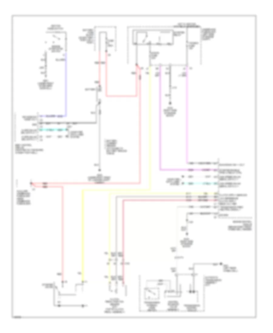
Starting Wiring Diagram for Chevrolet Corvette Stingray 2014
List of elements for Starting Wiring Diagram for Chevrolet Corvette Stingray 2014:
- Automatic transmission assembly (a/t)
- Auxiliary underhood fuse block (near underhood fuse block)
- Battery
- Battery current sensor (attached to battery ground cable)
- Battery fuse block (on battery positive (+) post)
- Body control module (mounted on toe board, in right footwell)
- Clutch pedal position sensor (m/t) (top of clutch pedal assembly)
- Computer data lines system
- Control solenoid valve assembly
- Engine control module (behind right front wheelwell fender)
- Engine start/stop switch
- Fuse 350a
- G100 (right side of engine block)
- G201 (under front of driver's door sill)
- G303 (under right front of luggage compt carpet)
- G401 (left rear wheelwell)
- Gnd
- Hi spd gmlan srl data (+) 1
- Hi spd gmlan srl data (-) 1
- High speed gmlan serial data (+) 1
- High speed gmlan serial data (-) 1
- Hot w/ ignition main relay energized
- Ign mode sw mode volt
- Ignition mode switch
- J118
- J120
- J200
- Low reference
- Red
- Run/crank ign 1 volt
- Sig gnd
- Starter enable (ppei 3) relay ctrl
- Starter motor
- Starter relay
- Strtr fuse 30a
- Tcm/ecm fuse 15a
- Transmission control module
- Transmission internal mode switch
- Transmission park/ neutral signal 1
- Underhood fuse block (left side of engine compt)
- X100
- X174
- X2 a
- X201

 Čeština
 Dansk
Dansk Deutsch
 Ελληνικά
 English
 English
 Español
 Suomi
Suomi Français
 Français
 עברית
עברית Hrvatski
 Magyar
 日本語
日本語 한국어
한국어 Nederlands
 Polski
 Português
 Português
 Română
 Русский
 Slovenčina
 Slovenščina
 Svenska
 Türkçe
 中文 (中国)