ACTIVE BODYWORKS
Active Bodyworks Wiring Diagram for BMW 535i GT 2010
 https://portal-diagnostov.com/license.html
Automotive Electricians Portal FZCO
Automotive Electricians Portal FZCO
https://portal-diagnostov.com/license.html
https://portal-diagnostov.com/license.html
Automotive Electricians Portal FZCO
Automotive Electricians Portal FZCO
List of elements for Active Bodyworks Wiring Diagram for BMW 535i GT 2010:
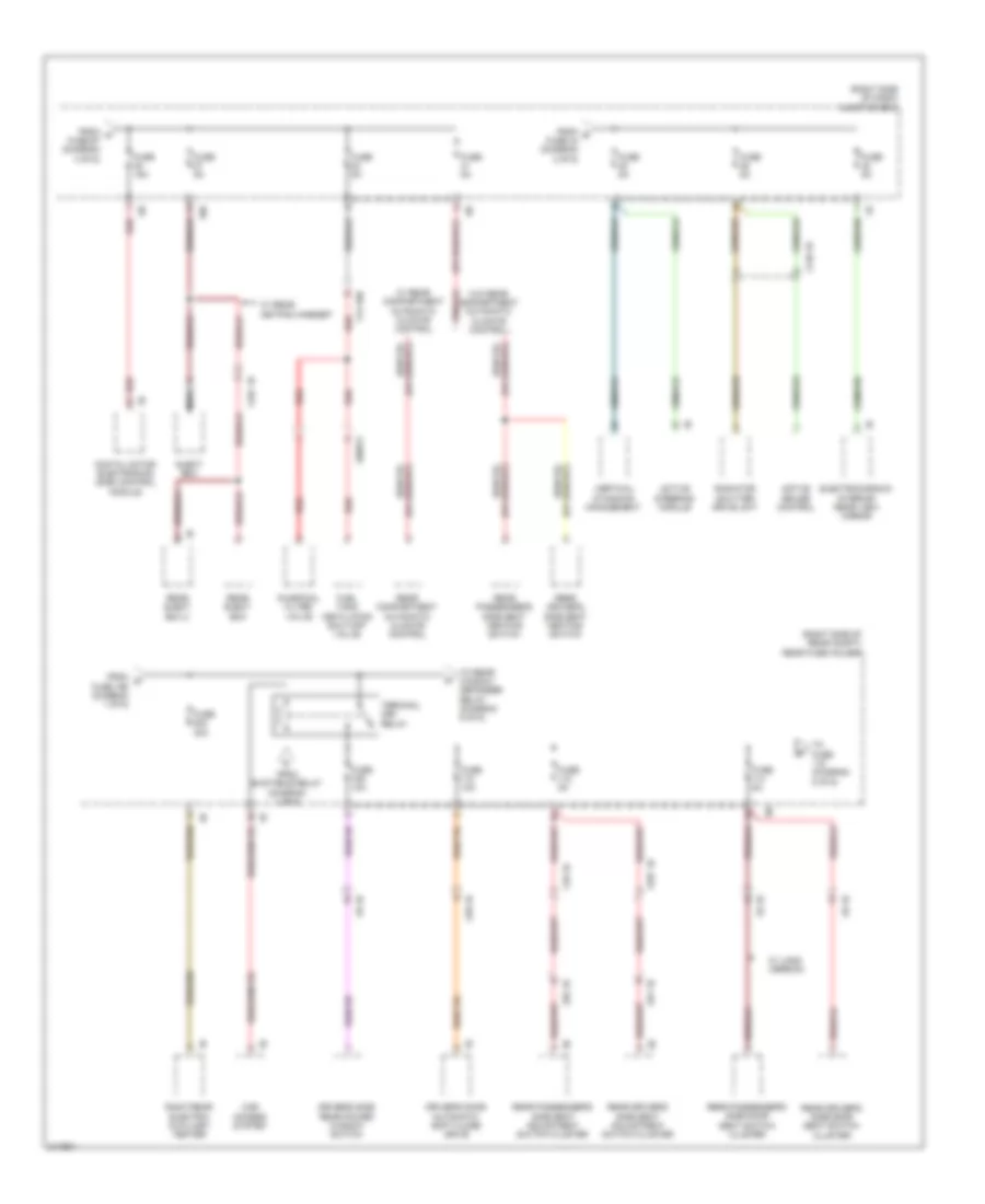
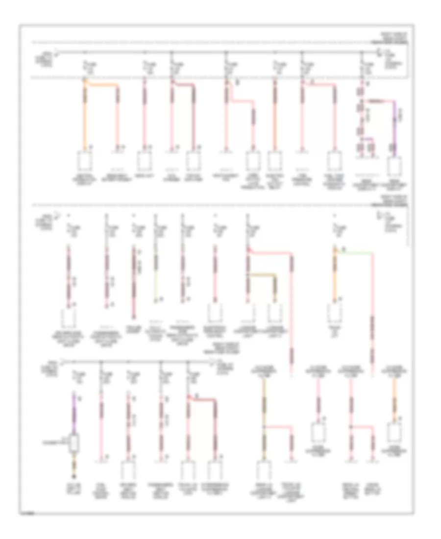
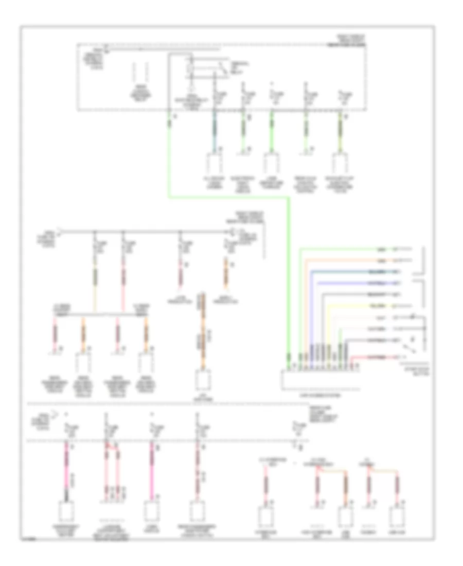
- (right side of cargo area) z10 8b
- (under spare tire) trailer module
- Fully automatic towing hitch
- Fully automatic towing hitch button
- Fully automatic towing hitch drive
- Fuse 20a
- Hot w/ terminal 30b relay energized
- Nca
- Rear fuse holder (right side of rear compt)
- Trailer socket switch
- X268 1b
- X269 1b
- Z10 8b (right side of cargo area)
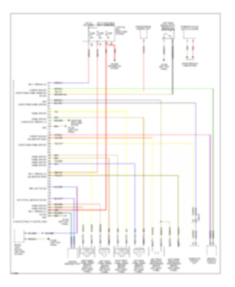
AIR CONDITIONING
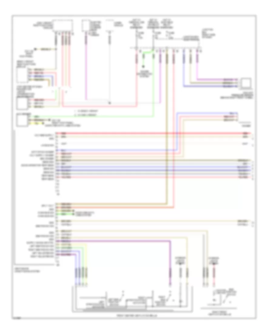
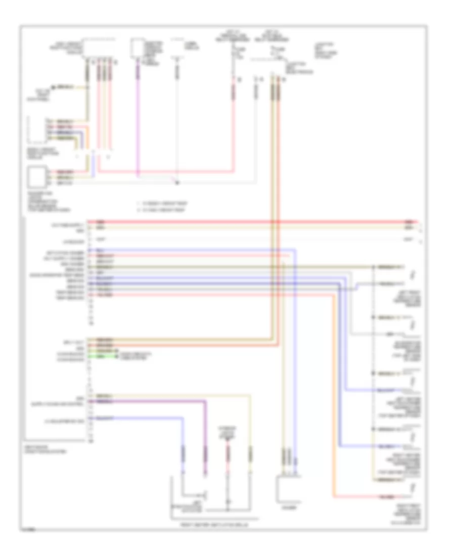
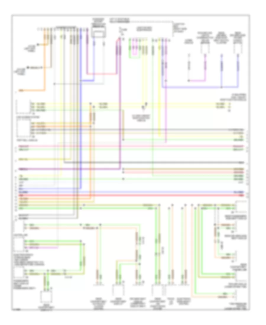
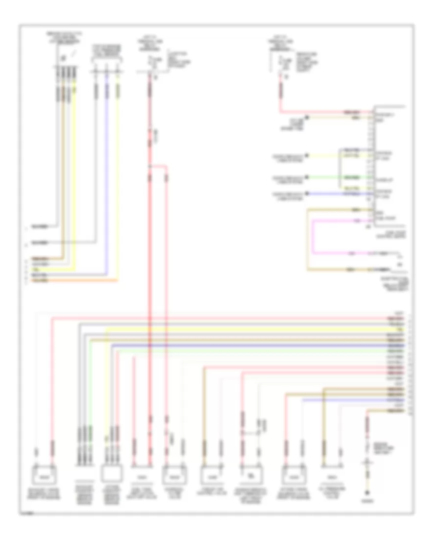
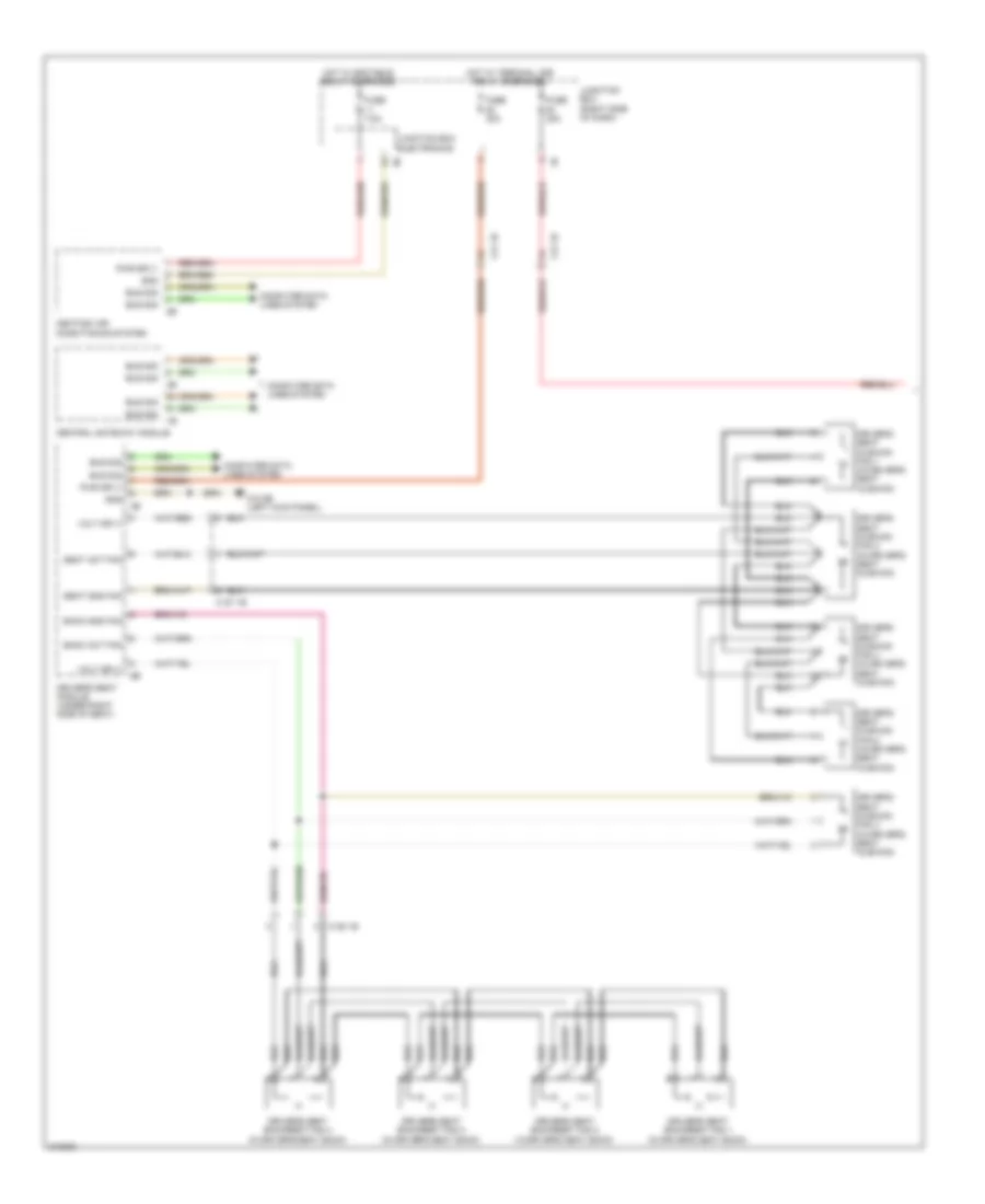
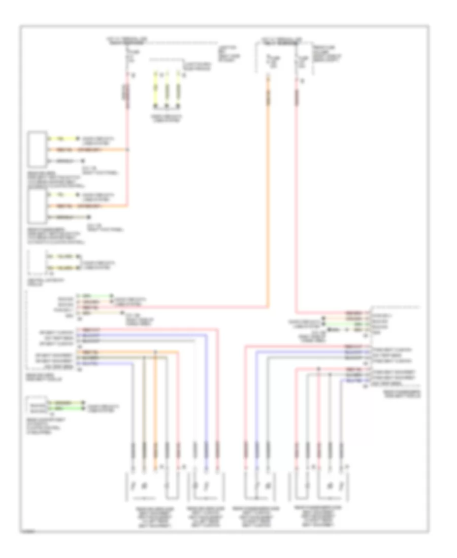
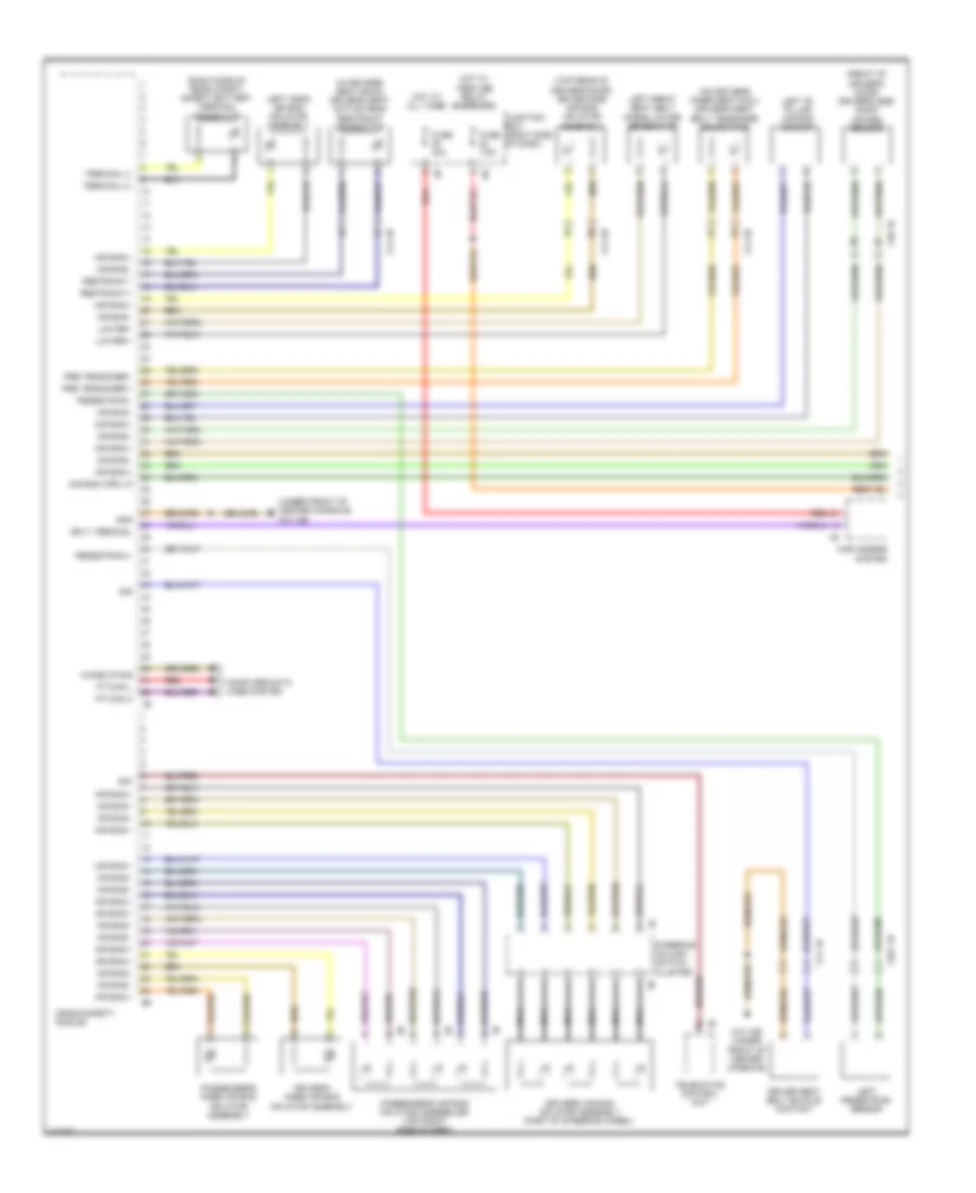
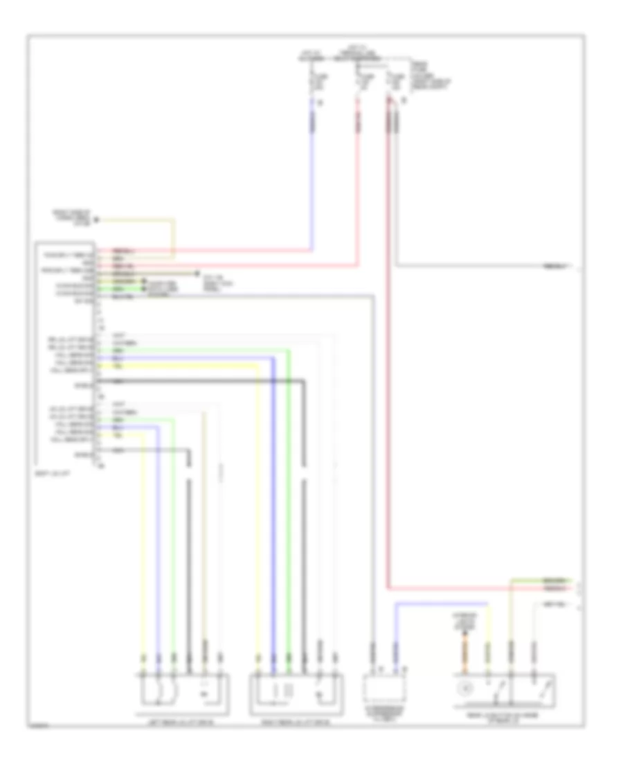
Automatic A/C Wiring Diagram, with Rear Automatic Climate Control (1 of 4) for BMW 535i GT 2010
List of elements for Automatic A/C Wiring Diagram, with Rear Automatic Climate Control (1 of 4) for BMW 535i GT 2010:
- (top center of dash) rain/driving lights/ condensation/ solar sensor
- Activation ioniser
- Auc sensor
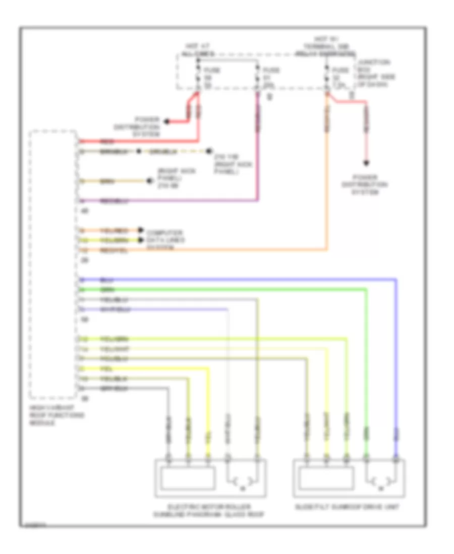
- Basic variant roof functions module
- Computer data lines system
- Coolant pressure sensor (behind right front wheel)
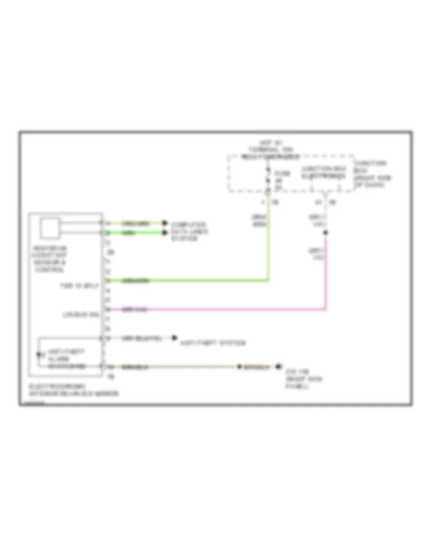
- Electro- chromic interior rear view 1b mirror
- End pos sw sig
- End position switch
- Front center ventilation grille
- Fuse 5a
- Fuse 7.5a
- Gnd
- Gnd ioniser
- Heating/air conditioning system
- High variant roof functions module
- Hot w/ bi-stable relay energized
- Hot w/ terminal 15n relay energized
- Hot w/ terminal 30b relay energized
- Interior lights system
- Ioniser
- Junction box (right side of dash)
- Junction box electronics
- K-can bus sig
- Left adjuster sig
- Left end pos sw sig
- Left end position switch
- Left stratification actuator
- Lin bus sig
- Locator lighting
- Power distribution system
- Red
- Right adjuster sig
- Right end pos sw sig
- Right end position switch
- Right front ventilation grille
- Right stratification actuator
- Sens gnd
- Sens sig
- Sig evaporator temp sens
- Sply volt
- Temp sens
- W/ basic variant
- W/ high variant
- Wiper module
- Z10 11b (right kick panel)
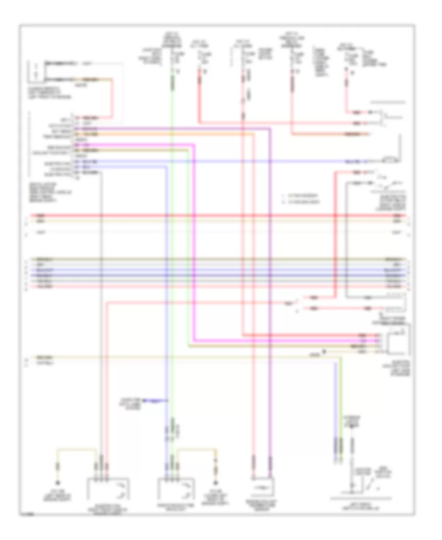
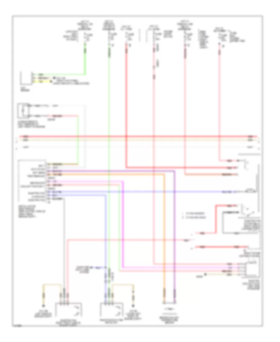
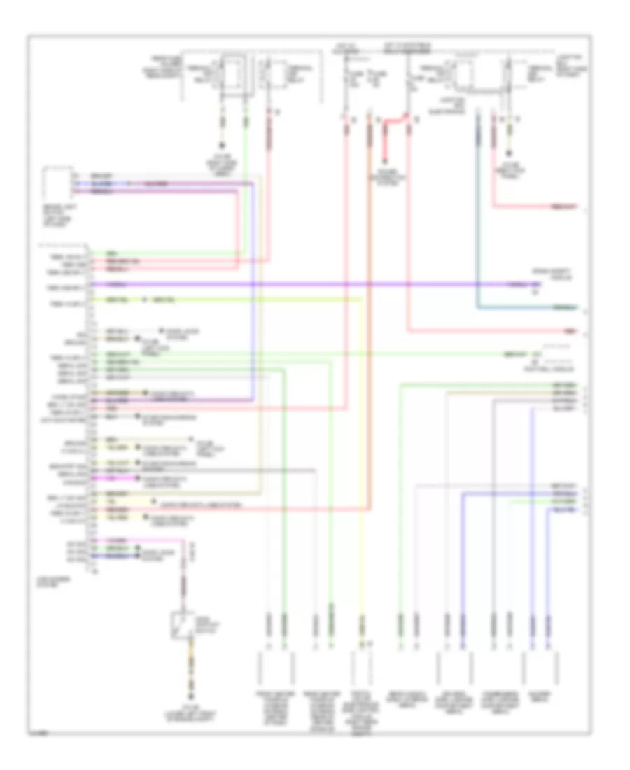
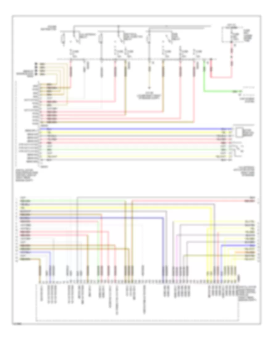
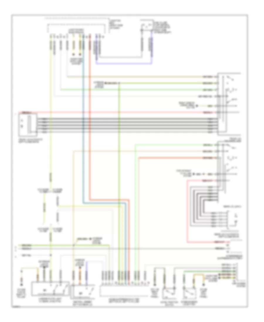
Automatic A/C Wiring Diagram, with Rear Automatic Climate Control (2 of 4) for BMW 535i GT 2010
List of elements for Automatic A/C Wiring Diagram, with Rear Automatic Climate Control (2 of 4) for BMW 535i GT 2010:
- Activation
- Bsd bus sig
- Characteristic map thermostat (left front of engine)
- Computer data lines system
- Coolant pump sply
- Digital motor electronics (dme) control module (right rear engine compt)
- Ect sens
- Electric coolant pump (left side of engine)
- Electric fan
- Electric fan (right front side of engine compt)
- Electric fan cutoff relay (right side of luggage compt)
- End position switch
- Engine coolant temperature sensor
- Front power distribution box
- Fuse 100a
- Fuse 50a
- Fuse 5a
- Fuse 60a
- Fuse 7.5a
- Fuse box (under spare tire)
- Hot at all times
- Hot w/ terminal 15n relay energized
- Hot w/ terminal 30b relay energized
- Interior lights system
- Junction box (right side of dash)
- Left front ventilation grille
- Lin bus sig
- Locator lighting
- Nca
- Power distri- bution
- Radiator shutter drive unit
- Rear fuse holder (right side of rear compt)
- Red
- Sply
- Temp sens sig
- W/ fan 400/600w
- W/ fan 800/1000w
- X148 1b
- X60002
- X60003
- X60183
- X60571
- X62790
- X6455
- Z10 15b (left rear of engine compt)
- Z10 2b (lower left front of engine compt)
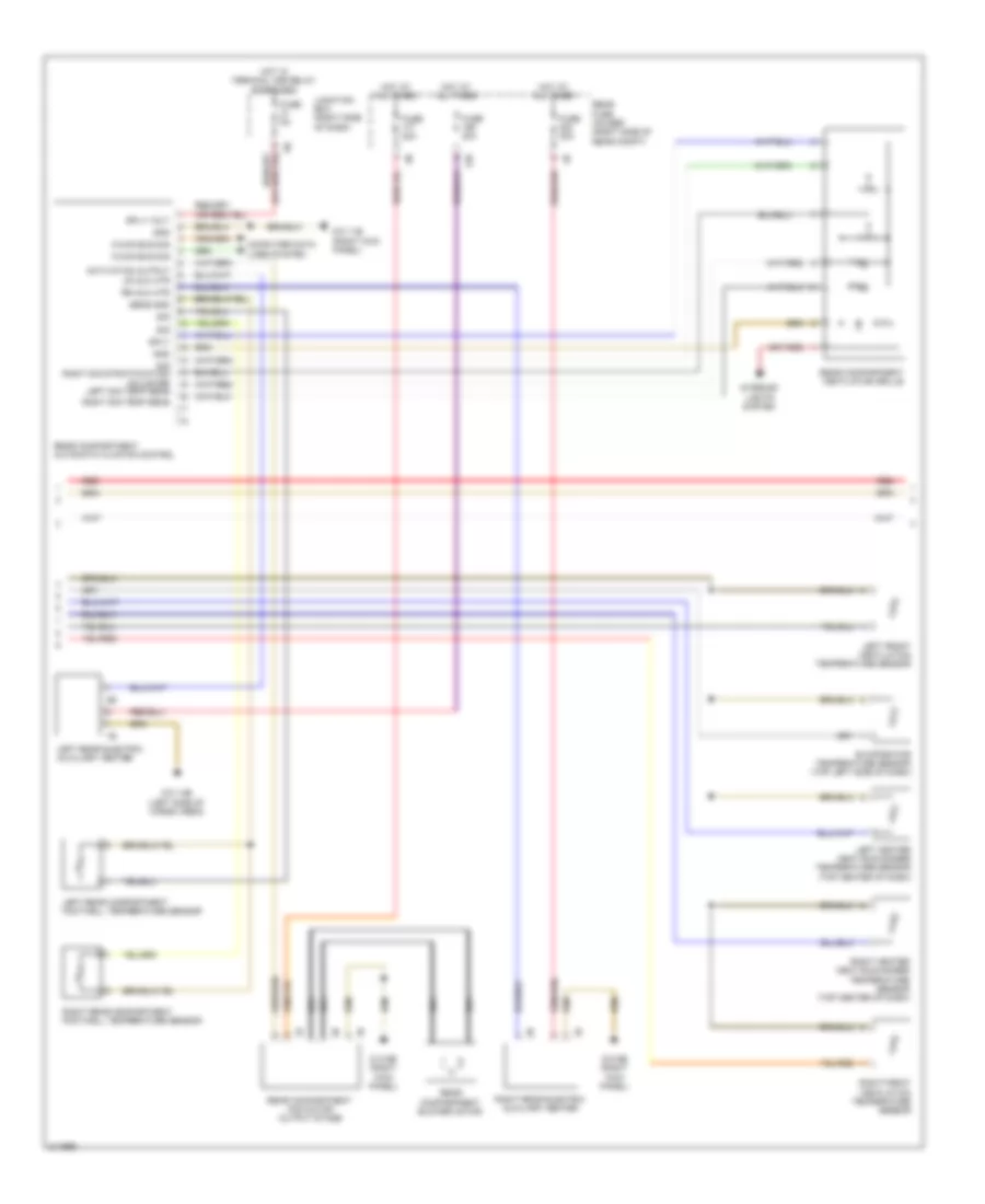
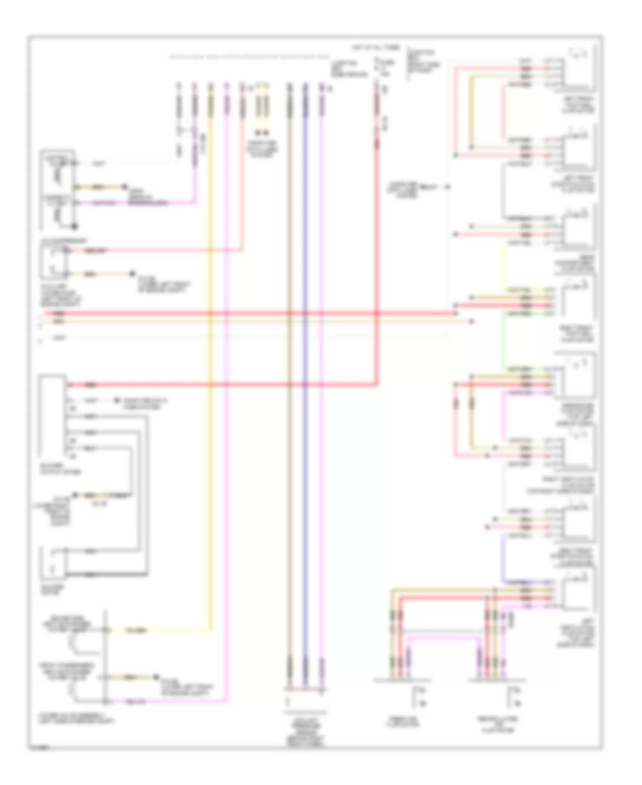
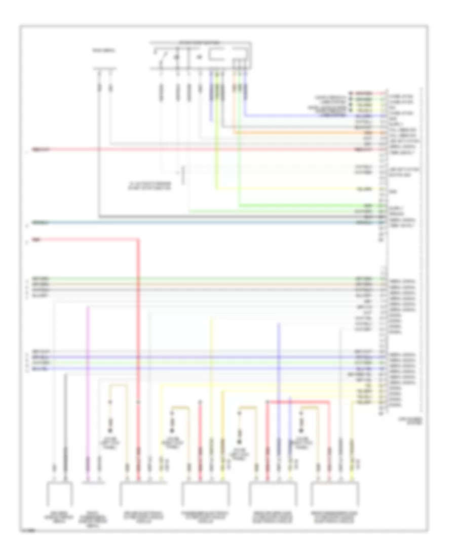
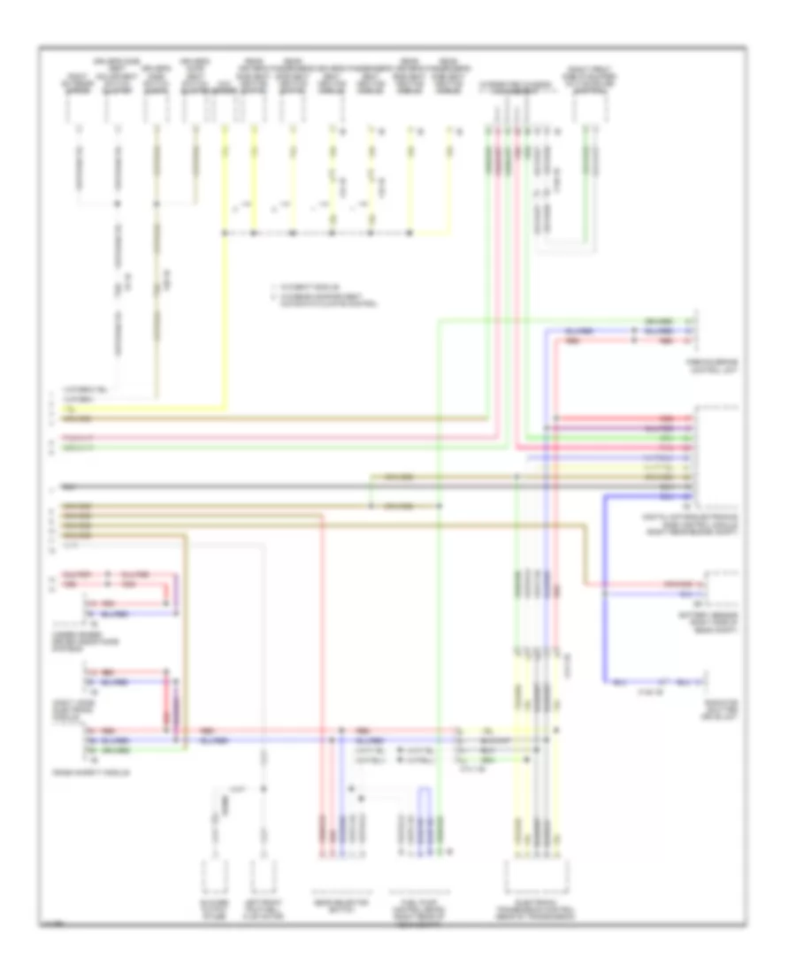
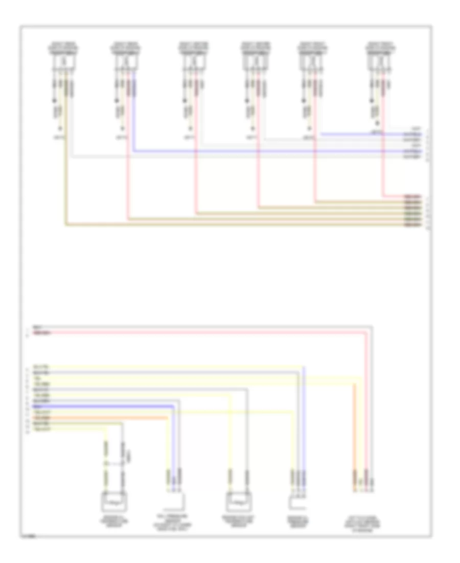
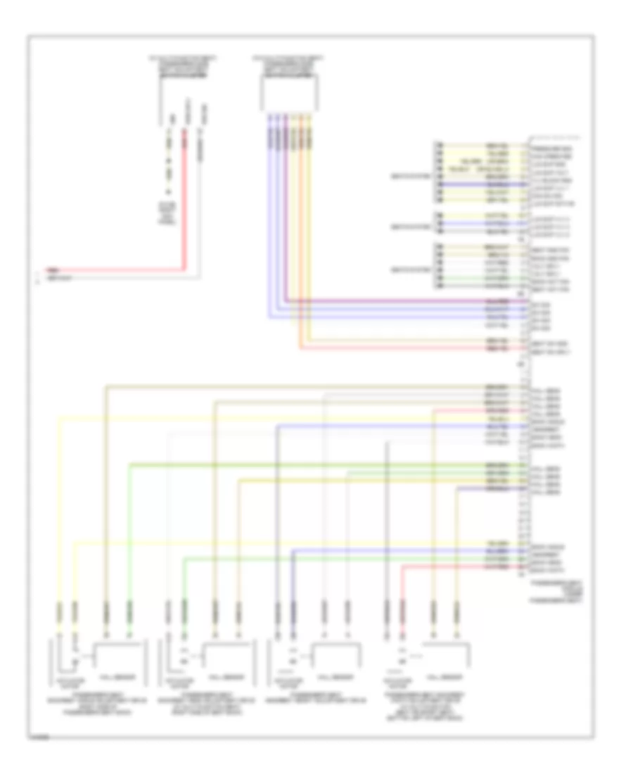
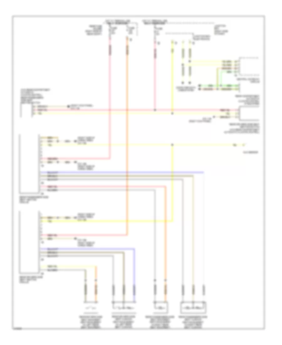
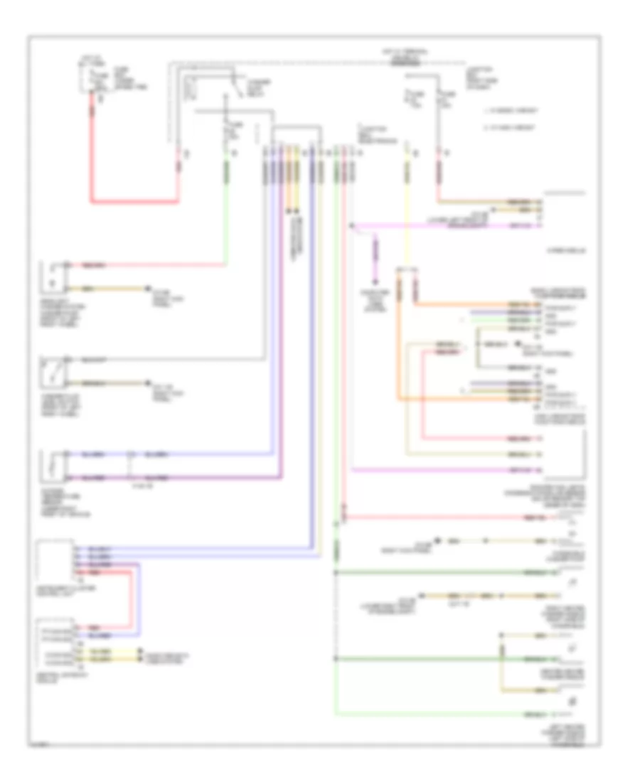
Automatic A/C Wiring Diagram, with Rear Automatic Climate Control (3 of 4) for BMW 535i GT 2010
List of elements for Automatic A/C Wiring Diagram, with Rear Automatic Climate Control (3 of 4) for BMW 535i GT 2010:
- 12b
- Activation output
- Computer data lines system
- Evaporator temperature sensor (top left side of dash)
- Fuse 20a
- Fuse 30a
- Fuse 5a
- Gnd
- Hot at all times
- Hot w/ terminal 30b relay energized
- Interior lights system
- Junction box (right side of dash)
- K-can bus sig
- Left front ventilation temperature sensor
- Left heater heat exchanger temperature sensor (top center of dash)
- Left rear compartment footwell temperature sensor
- Left rear electric auxiliary heater
- Left sig temp sens
- Lr aux htr
- Nca
- Rear compartment automatic climate control
- Rear compartment blower motor
- Rear compartment fan motor output stage
- Rear compartment ventilation grille
- Rear fuse holder (right side of rear compt)
- Red
- Right front ventilation temperature sensor
- Right heater heat exchanger temperature sensor (top center of dash)
- Right rear compartment footwell temperature sensor
- Right rear electric auxiliary heater
- Right sig temp sens
- Rr aux htr
- Sens gnd
- Sig
- Sig right sig stratification adjuster
- Sply
- Sply volt
- Z10 11b (right kick panel)
- Z10 14b (left side of cargo area)
- Z10 6b (right kick panel)
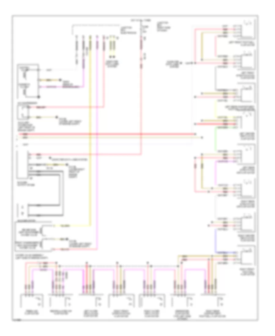
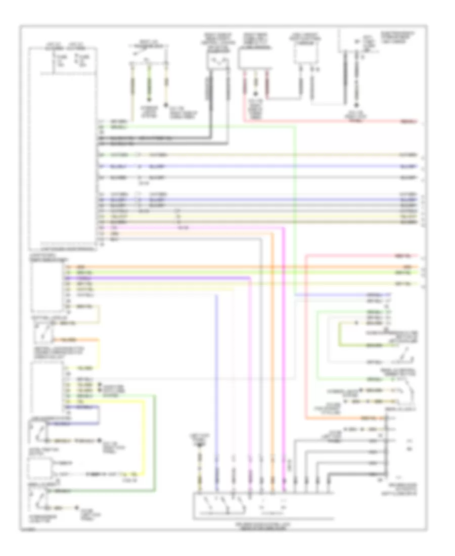
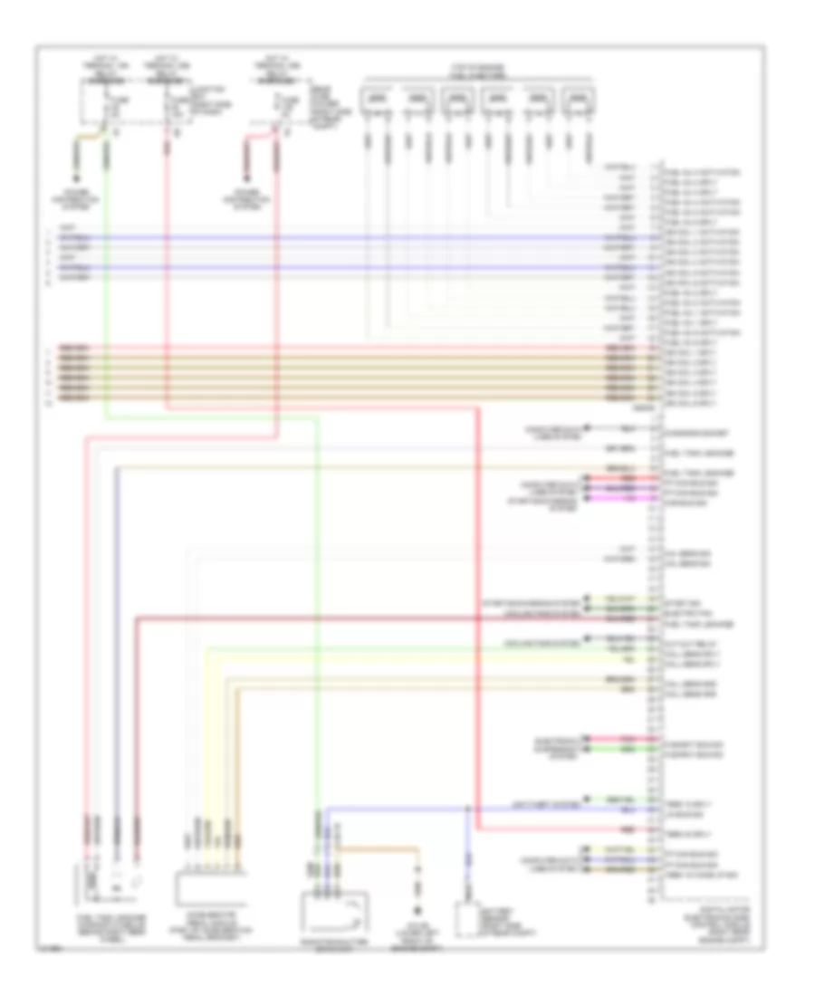
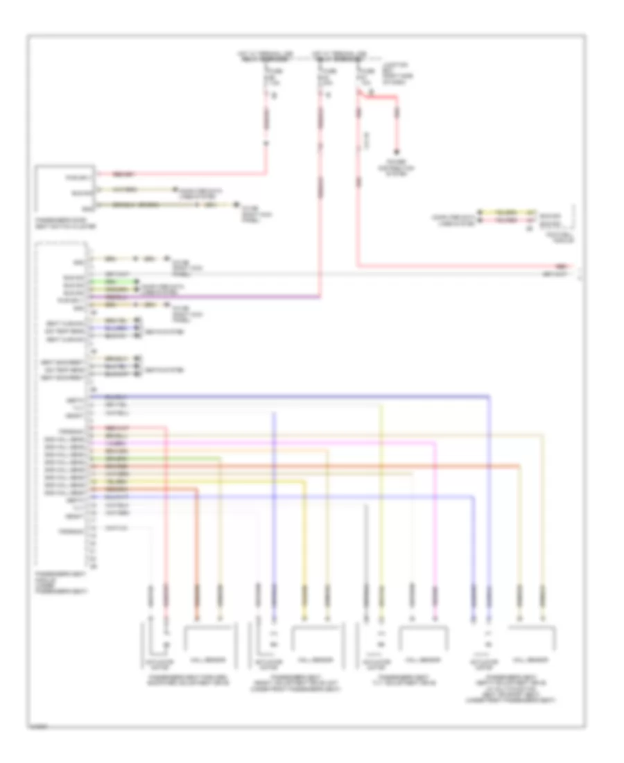
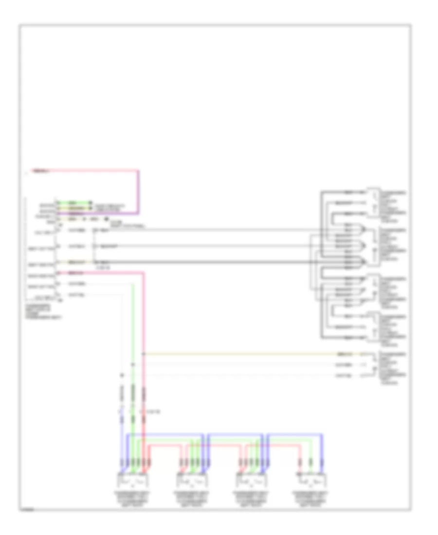
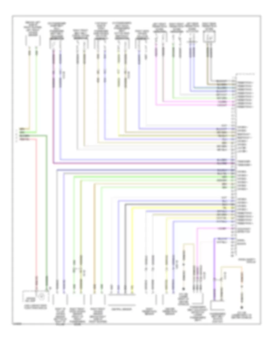
Automatic A/C Wiring Diagram, with Rear Automatic Climate Control (4 of 4) for BMW 535i GT 2010
List of elements for Automatic A/C Wiring Diagram, with Rear Automatic Climate Control (4 of 4) for BMW 535i GT 2010:
- 13b
- A/c compressor
- Auxiliary water pump (left front of engine compt)
- Blower motor
- Blower output stage
- Computer data lines system
- Control valve
- Defroster flap motor (top left side of dash)
- Driver side heat exchanger water valve
- Fresh air flap motor
- Front passenger's heat exchanger water valve
- Fuse 40a
- Hot at all times
- Junction box (right side of dash)
- Junction box electronics
- Left center ventilation flap motor
- Left front footwell flap motor
- Left front stratification flap motor
- Left outer ventilation flap motor
- Left rear compartment footwell flap motor
- Left rear stratifying air flap motor
- Magnetic clutch
- N2 1b
- Nca
- Recirculated air flap motor
- Red
- Right center ventilation flap motor
- Right front footwell flap motor
- Right front stratification flap motor
- Right outer ventilation flap motor
- Right rear compartment footwell flap motor
- Right rear stratifying air flap motor
- Water valve assembly (left side of engine compt)
- X01001
- X13 10b
- X6454 (rear of engine block)
- Z10 2b (lower left front of engine compt)
- Z10 3b (lower right front of engine compt)
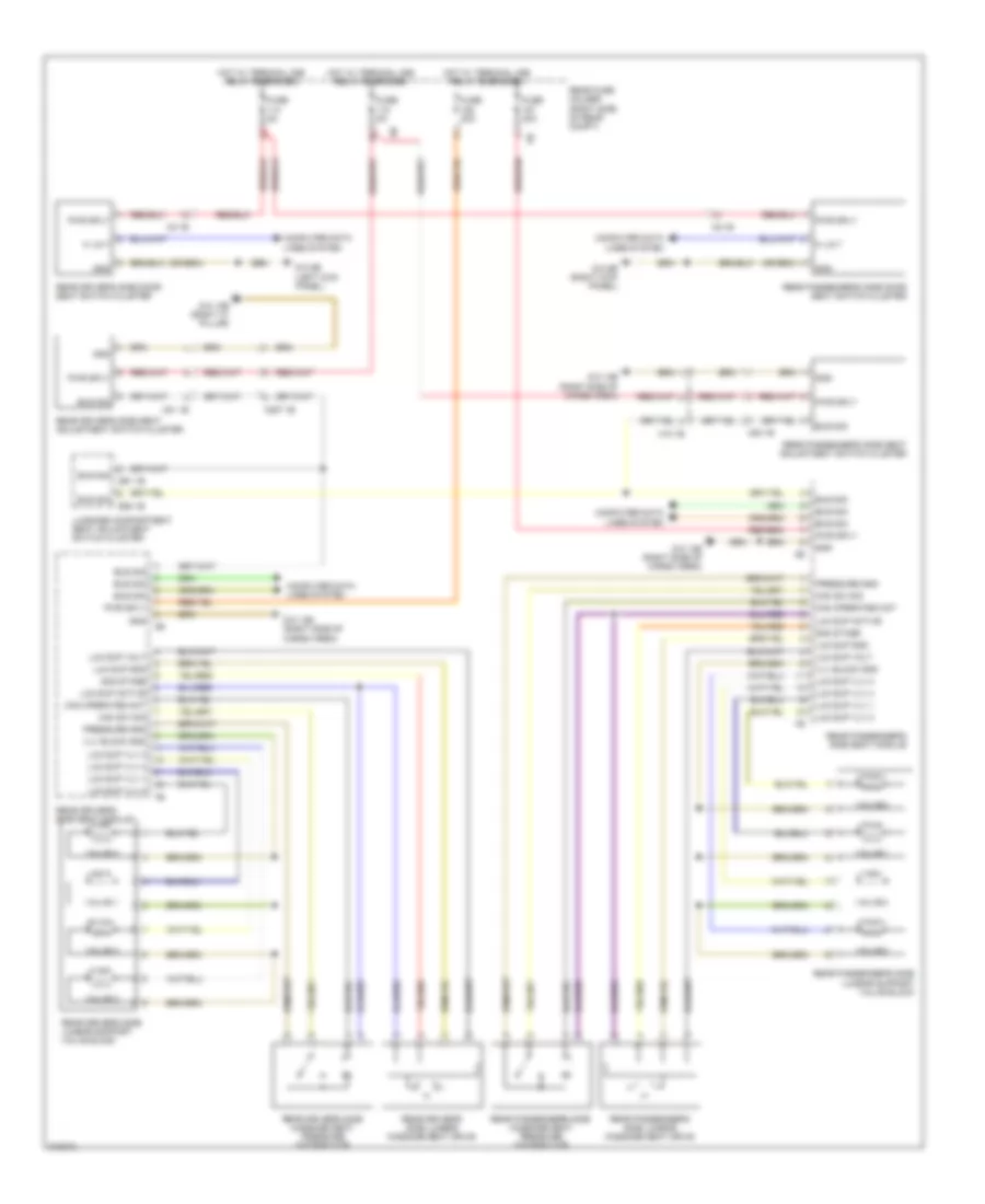
Automatic A/C Wiring Diagram, without Rear Automatic Climate Control (1 of 3) for BMW 535i GT 2010
List of elements for Automatic A/C Wiring Diagram, without Rear Automatic Climate Control (1 of 3) for BMW 535i GT 2010:
- Activation ioniser
- Basic variant roof functions module
- Computer data lines system
- Electro- chromic interior rear view 1b mirror
- Evaporator temperature sensor (top left side of dash)
- Front center ventilation grille
- Fuse 7.5a
- Gnd
- Gnd ioniser
- Heating/air conditioning system
- High variant roof functions module
- Hot w/ bi-stable relay energized
- Hot w/ terminal 30b relay energized
- Interior lights system
- Ioniser
- Junction box (right side of dash)
- Junction box electronics
- K-can bus sig
- Left front ventilation temperature sensor
- Left heater heat exchanger temperature sensor (top center of dash)
- Left stratification actuator
- Lh adjuster sw sig
- Lin bus sig
- Rain/driving lights/ condensation/ solar sensor (top center of dash)
- Red
- Right front ventilation temperature sensor (w/ 2.5 zone a/c)
- Right heater heat exchanger temperature sensor (top center of dash)
- Sens gnd
- Sens sig
- Sig evaporator temp sens
- Sply volt
- Temp sens sig
- W/ basic variant roof
- W/ high variant roof
- Wiper module
- Z10 11b (right kick panel)
Automatic A/C Wiring Diagram, without Rear Automatic Climate Control (2 of 3) for BMW 535i GT 2010
List of elements for Automatic A/C Wiring Diagram, without Rear Automatic Climate Control (2 of 3) for BMW 535i GT 2010:
- Activation
- Auc sensor
- Bsd bus sig
- Characteristic map thermostat (left front of engine)
- Computer data lines system
- Coolant pump sply
- Digital motor electronics (dme) control module (right rear engine compt)
- Ect sens
- Electric coolant pump (left side of engine)
- Electric fan
- Electric fan (right front side of engine compt)
- Electric fan cutoff relay (right side of luggage compt)
- Engine coolant temperature sensor
- Front power distribution box
- Fuse 100a
- Fuse 50a
- Fuse 5a
- Fuse 60a
- Fuse 7.5a
- Fuse box (under spare tire)
- Hot at all times
- Hot w/ terminal 15n relay energized
- Hot w/ terminal 30b relay energized
- Junction box (right side of dash)
- Lin bus sig
- Nca
- Power distri- bution
- Radiator shutter drive unit
- Rear fuse holder (right side of rear compt)
- Red
- Sply
- Temp sens sig
- W/ fan 400/600w
- W/ fan 800/1000w
- X148 1b
- X60002
- X60003
- X60183
- X60571
- X62790
- X6455
- Z10 11b (right kick panel)
- Z10 15b (left rear of engine compt)
- Z10 2b (lower left front of engine compt)
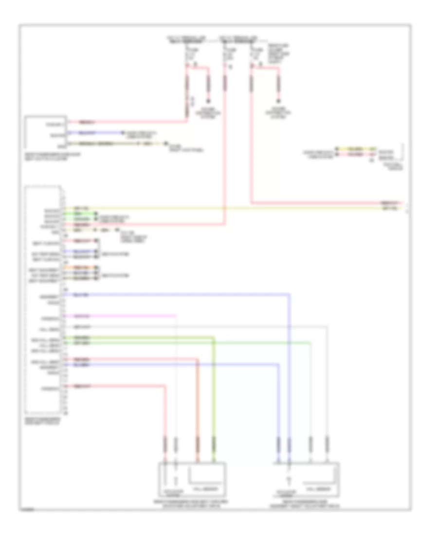
Automatic A/C Wiring Diagram, without Rear Automatic Climate Control (3 of 3) for BMW 535i GT 2010
List of elements for Automatic A/C Wiring Diagram, without Rear Automatic Climate Control (3 of 3) for BMW 535i GT 2010:
- 13b
- A/c compressor
- Auxiliary water pump (left front of engine compt)
- Blower motor
- Blower output stage
- Computer data lines system
- Control valve
- Coolant pressure sensor (behind right front wheel)
- Defroster flap motor (top left side of dash)
- Driver side heat exchanger water valve
- Fresh air flap motor
- Front passenger's heat exchanger water valve
- Fuse 40a
- Hot at all times
- Junction box (right side of dash)
- Junction box electronics
- Left front footwell flap motor
- Left front stratification flap motor
- Left ventilation flap motor (top left side of dash)
- Magnetic clutch
- N2 1b
- Nca
- Rear compartment flap motor
- Recirculated air flap motor
- Red
- Right front footwell flap motor
- Right front stratification flap motor
- Right ventilation flap motor (top right side of dash)
- Water valve assembly (left side of engine compt)
- X01001
- X13 10b
- X6454 (rear of engine block)
- Z10 2b (lower left front of engine compt)
- Z10 3b (lower right front of engine compt)
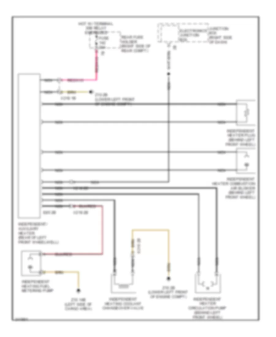
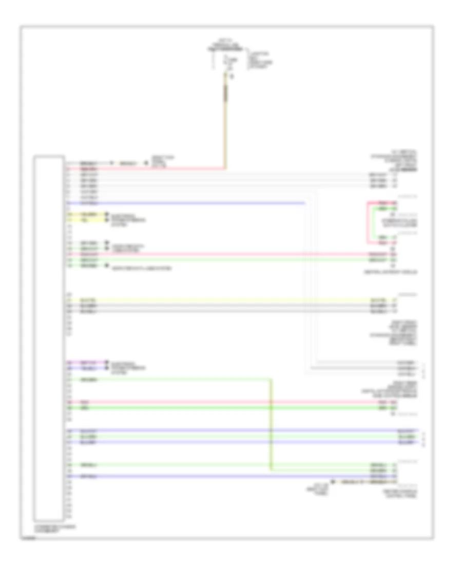
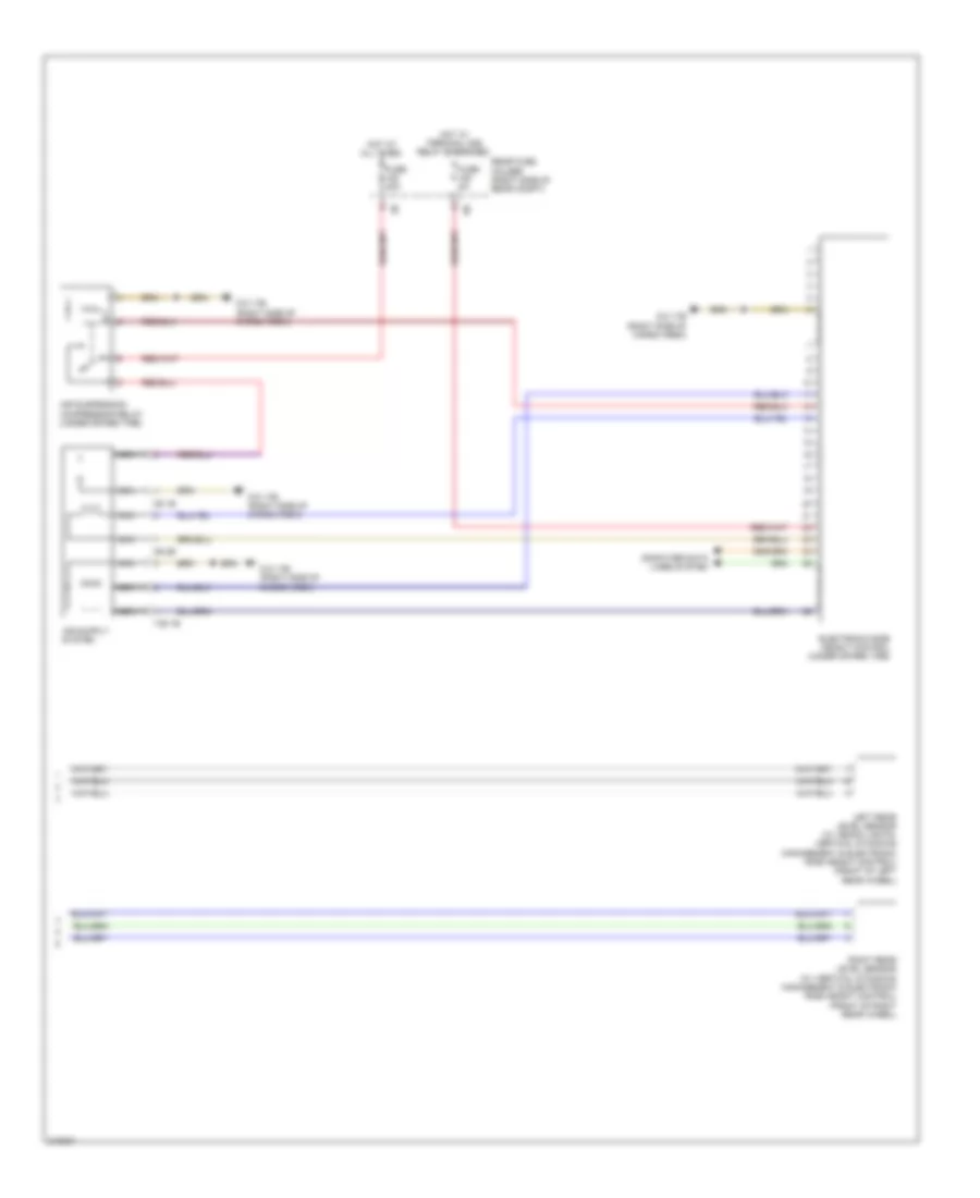
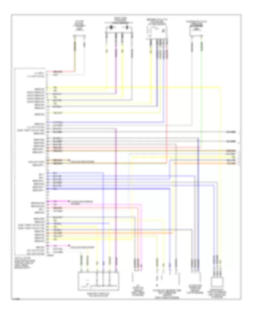
Independent Heating Wiring Diagram for BMW 535i GT 2010
List of elements for Independent Heating Wiring Diagram for BMW 535i GT 2010:
- E85 2b
- Electronics junction box
- Fuse 20a
- Hot w/ terminal 30b relay energized
- Independent heater circulation pump (behind left front wheel)
- Independent heater combustion air blower (behind left front wheel)
- Independent heater plug (behind left front wheel)
- Independent heating coolant changeover valve
- Independent heating fuel metering pump
- Independent/ auxiliary heater (rear of left front wheelwell)
- Junction box (right side of dash)
- Nca
- Rear fuse holder (right side of rear compt)
- X218 1b
- X218 2b
- Z10 14b (left side of cargo area)
- Z10 2b (lower left front of engine compt)
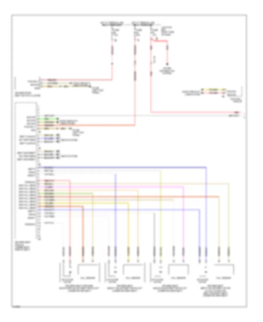
ANTI-LOCK BRAKES
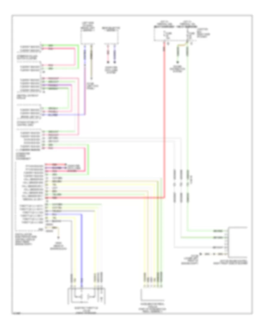
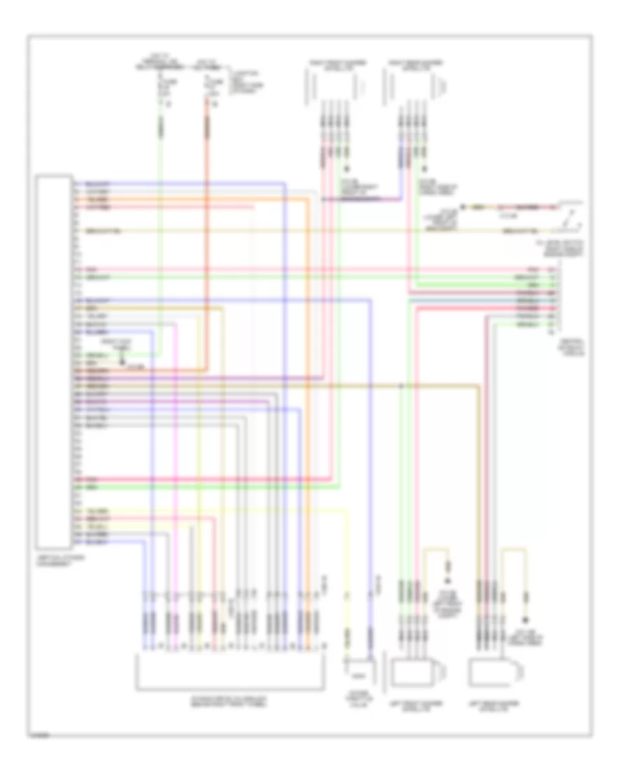
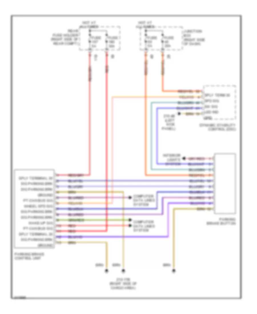
Anti-lock Brakes Wiring Diagram for BMW 535i GT 2010
List of elements for Anti-lock Brakes Wiring Diagram for BMW 535i GT 2010:
- (left rear engine compt) brake fluid level switch
- 13b
- Activation, led function ind
- Brake light switch (left side of dash)
- Brk light sw sig
- Central gateway module
- Computer data lines system
- Conditioned wheel spd sig
- Conditioned wheel speed sig
- Dynamic stability control (dsc)
- Flexray bus sig
- Fuse 30a
- Fuse 50a
- Fuse 5a
- Gnd
- Hot at all times
- Hot w/ bi-stable relay energized
- Junction box (right side of dash)
- Left front brake pad wear sensor (behind left front wheel)
- Left front wheel speed sensor (front of left front wheel)
- Left rear wheel speed sensor (front of left rear wheel)
- Nca
- Parking brake button
- Parking brake control unit
- Pnk
- Power distribution system
- Red
- Right front wheel speed sensor (behind right front wheel)
- Right rear brake pad wear sensor (behind right rear wheel)
- Right rear wheel speed sensor (front of right rear wheel)
- Sig, brk pad wear
- Sply, terminal 30
- Steering column switch cluster
- Sw sig
- Telematics control unit
- Wake-up sig, terminal 15
- Wheel spd sig
- X188 1b
- Z10 4b (left kick panel)
- Z10 9b (left kick panel)
ANTI-THEFT
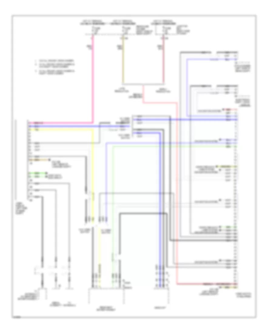
Access/Start Wiring Diagram (1 of 2) for BMW 535i GT 2010
List of elements for Access/Start Wiring Diagram (1 of 2) for BMW 535i GT 2010:
- Active starter
- Aerial sig
- Brake light switch (left side of dash)
- Brk lt sw sig
- Bumper aerial
- Car access system
- Cas bus
- Computer data lines system
- Crash safety module
- Digital motor electronics (dme) control module (right rear engine compt)
- Door locks system
- Driver's side luggage compartment aerial
- Eng strt sig
- Footwell module
- Front center console interior antenna (center of dash)
- Fuse 40a
- Fuse 5a
- Ground
- Hood contact switch
- Hot at all times
- Hot w/ bi-stable relay energized
- Junction box (right side of dash)
- Junction box electronics
- K can 2-h
- K can 2-l
- Lin bus sig
- Passenger's side luggage compartment aerial
- Power distribution system
- Rear center console interior antenna (rear of center console)
- Rear fuse holder (right side of rear compt)
- Rear window shelf interior aerial
- Red
- Sig
- Starting/charging system
- Sw sig
- Term 15 sply
- Term 15n rly
- Term 30 sply
- Term 30b
- Term 30b sply
- Terminal 15n relay
- Terminal 30b relay
- Wake up sig
- X149 1b
- Z10 2b (lower left front of engine compt)
- Z10 5b (left kick panel)
- Z10 6b (right kick panel)
- Z10 8b (right side of cargo area)
- Z10 9b (left kick panel)
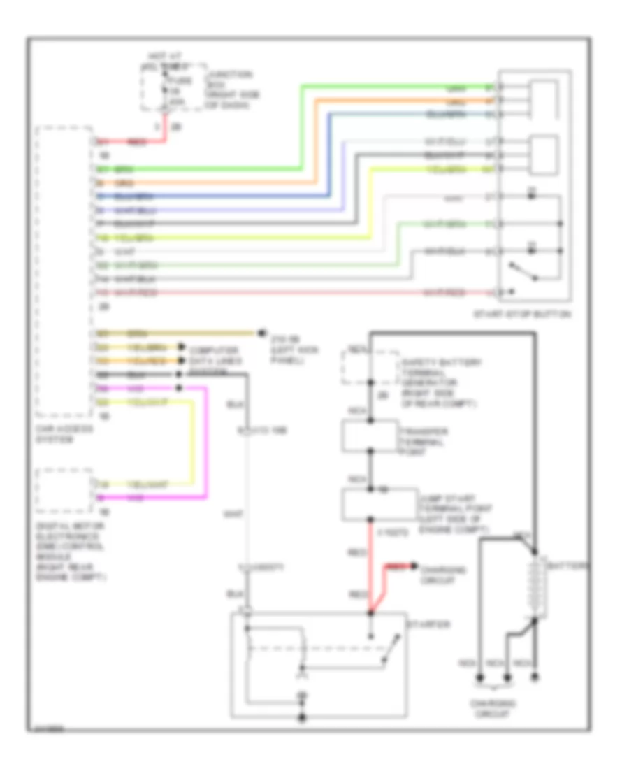
Access/Start Wiring Diagram (2 of 2) for BMW 535i GT 2010
List of elements for Access/Start Wiring Diagram (2 of 2) for BMW 535i GT 2010:
- Aerial signal
- Car access system
- Computer data lines system
- Door locks system computer data lines system
- Driver electronic outer door handle module
- Driver's side exterior aerial
- Front passenger's side exterior aerial
- Gnd
- Ground
- Hall sens sig
- Led activation
- Passenger electronic outer door handle module
- Rear driver's side outer door handle electronic module
- Rear passenger's side outer door handle electronic module
- Red
- Ring aerial
- Sig
- Signal
- Start-stop button
- Switch sig
- Term 15n rly
- Term 30b rly
- W/ automatic engine start stop function
- Wake up sig
- X28 1b
- X5 1b
- X8 1b
- X9 1b
- Z10 5b (left kick panel)
- Z10 6b (right kick panel)
Anti-theft & Central Locking Wiring Diagram (1 of 2) for BMW 535i GT 2010
List of elements for Anti-theft & Central Locking Wiring Diagram (1 of 2) for BMW 535i GT 2010:
- (left kick panel) z10 5b
- (right rear wheelwell) siren & tilt alarm sensor
- (right side of rear compt) central locking drive fuel filler flap
- Aerial diversity
- Anti- theft alarm led
- Boot lid/ tailgate lock
- Car access system
- Central locking button hazard warning switch operating unit
- Clr
- Computer data lines system
- Driver's door automatic soft-close drive
- Driver's door system lock (rear of driver's door)
- Electrochromic interior rear view mirror
- Footwell module
- Fuse 15a
- Fuse 20a
- High variant roof functions module
- Hot at all times
- Hotel position switch
- Interior lights system
- Interior rear lid button
- Junction box (right side of dash)
- Junction box electronics
- Nca
- Noise suppression filter (bottom of left "c" pillar)
- Rear lid central arrest button
- Rear lid lock 2
- X188 1b
- X28 1b
- X5 1b
- X8 1b
- X9 1b
- Z10 11b (right kick panel)
- Z10 17b (right side of cargo area)
- Z10 20b (top of right "c" pillar)
- Z10 5b (left kick panel)
Anti-theft & Central Locking Wiring Diagram (2 of 2) for BMW 535i GT 2010
List of elements for Anti-theft & Central Locking Wiring Diagram (2 of 2) for BMW 535i GT 2010:
- (left kick panel) z10 5b
- (right kick panel) z10 6b
- 11b
- Fuse 10a
- Fuse 5a
- Hot at all times
- Hot w/ terminal 30b relay energized
- Nca
- Passenger's door automatic soft-close drive
- Passenger's door system lock (rear of front passenger's seat)
- Rear driver's side automatic soft-close drive
- Rear driver's side system lock
- Rear fuse holder (right side of rear compt)
- Rear passenger's side automatic soft-close drive
- Rear passenger's side system lock
- X28 1b
- X5 1b
- X8 1b
- X9 1b
- Z10 5b (left kick panel)
- Z10 6b (right kick panel)
BODY CONTROL MODULES
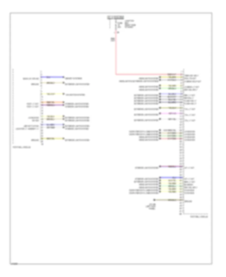
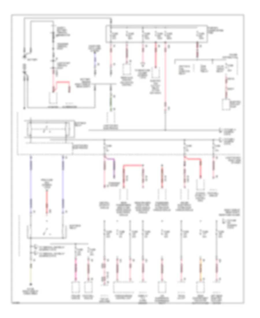
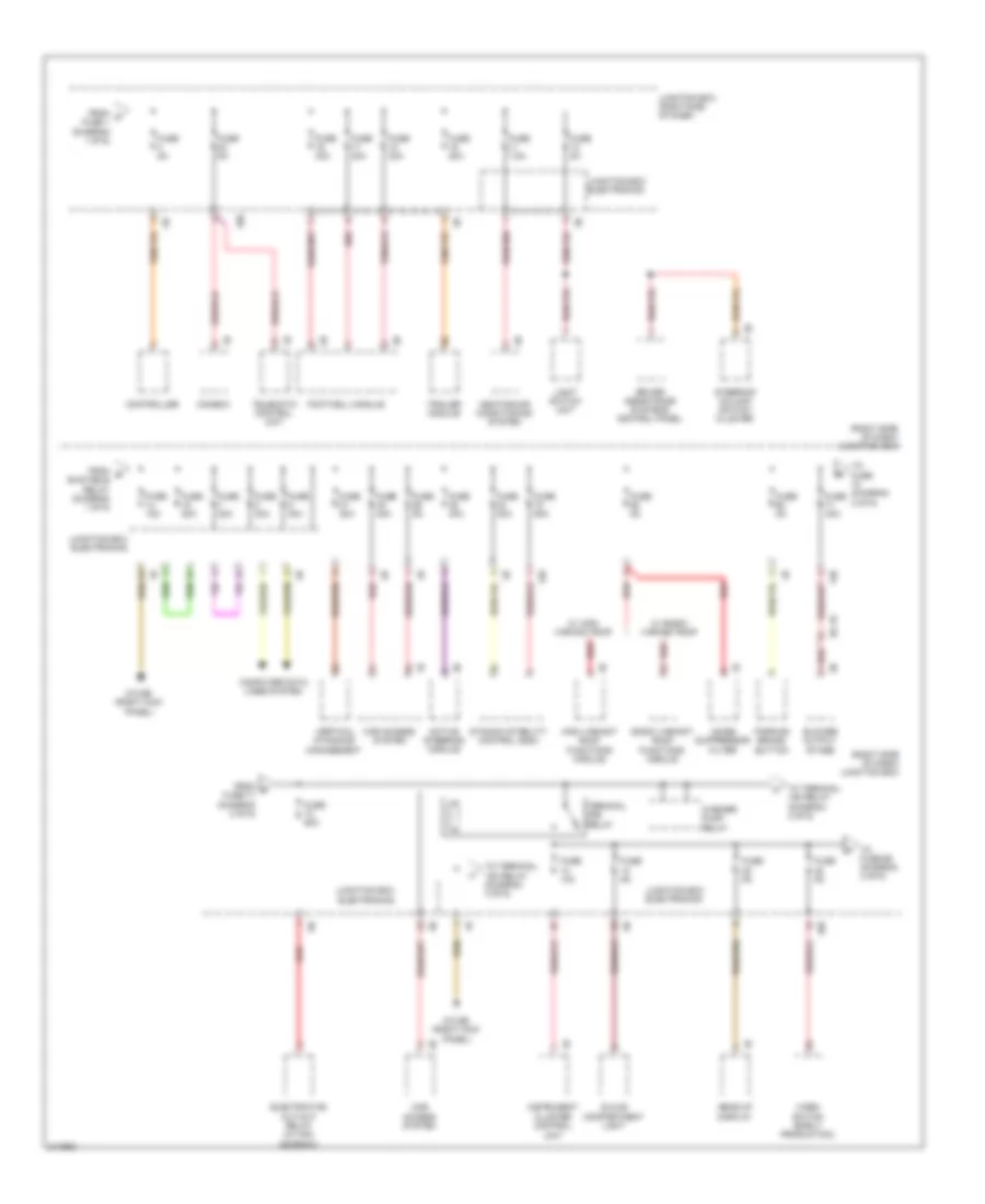
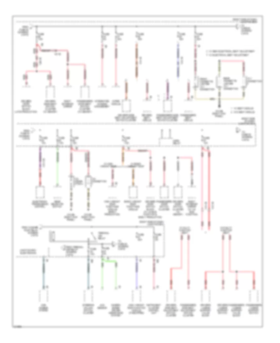
Body Control Modules Wiring Diagram (1 of 2) for BMW 535i GT 2010
List of elements for Body Control Modules Wiring Diagram (1 of 2) for BMW 535i GT 2010:
- Back up, d/r ind
- Bi-xenon
- Brk lt act
- Computer data lines system
- Drv mdl sply
- Exterior lights system
- Flash ind lt
- Fog lts act
- Foot lt act
- Footwell module
- Fuse 40a
- Ground
- Headlights & exterior lights systems
- Headlights system
- Hi beam hdlp act
- Hot w/ bi-stable relay energized
- Int lt act
- Interior lights system
- Junction box (right side of dash)
- K-can bus
- Led activation
- Lin bus sig
- Lo beam lt act
- Locator lt, ambient lt
- Memory systems
- Navigation system
- Rev lt act
- Rr fog lt
- Sw sig
- Tail lt act
- Term 30f, sply
- Z10 9b (left kick panel)
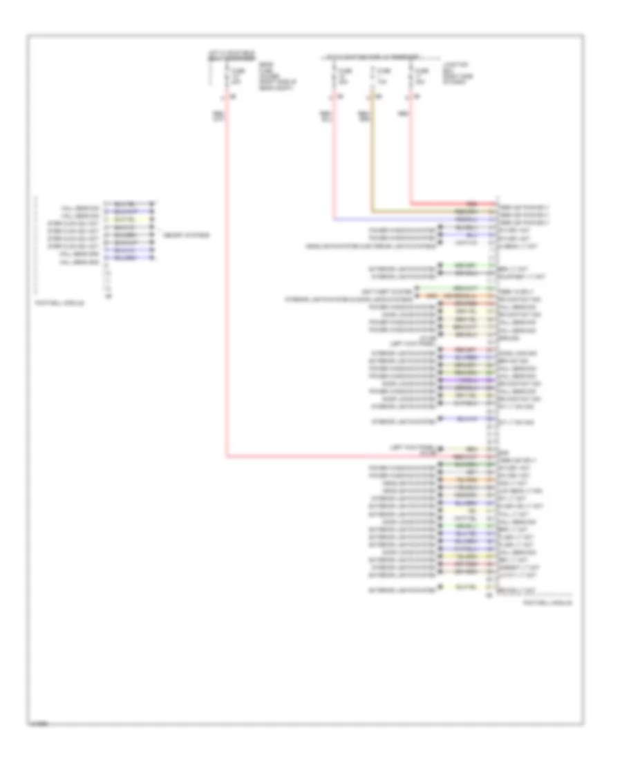
Body Control Modules Wiring Diagram (2 of 2) for BMW 535i GT 2010
List of elements for Body Control Modules Wiring Diagram (2 of 2) for BMW 535i GT 2010:
- (left kick panel) z10 5b
- Ambient lt act
- Anti-theft system
- Brk lt act
- Brk sw sig
- Cons load sig
- Courtesy lt act
- Door locks system
- Dr contact sig
- Exterior lights system
- Flash ind lt act
- Flash lt act
- Fog lt act
- Footwell module
- Fuse 10a
- Fuse 30a
- Fuse 40a
- Gnd
- Ground
- Hall sens gnd
- Hall sens sig
- Headlights system
- Headlights system & exterior lights systems
- Hi beam lt act
- Hot w/ bi-stable relay energized
- Int lt act
- Int lt sw sig
- Interior lights system
- Interior lights system & door locks systems
- Junction box (right side of dash)
- Lic plt lt act
- Low beam lt sig
- Memory systems
- Power windows system
- Pw drv act
- Rear fuse holder (right side of rear compt)
- Red
- Rev lt act
- Rr fog lt act
- Ster clmn adj act
- Tail lt act
- Term 15 sply
- Term 30f pwr sply
- Term 30f sply
- Z10 9b (left kick panel)
COMPUTER DATA LINES
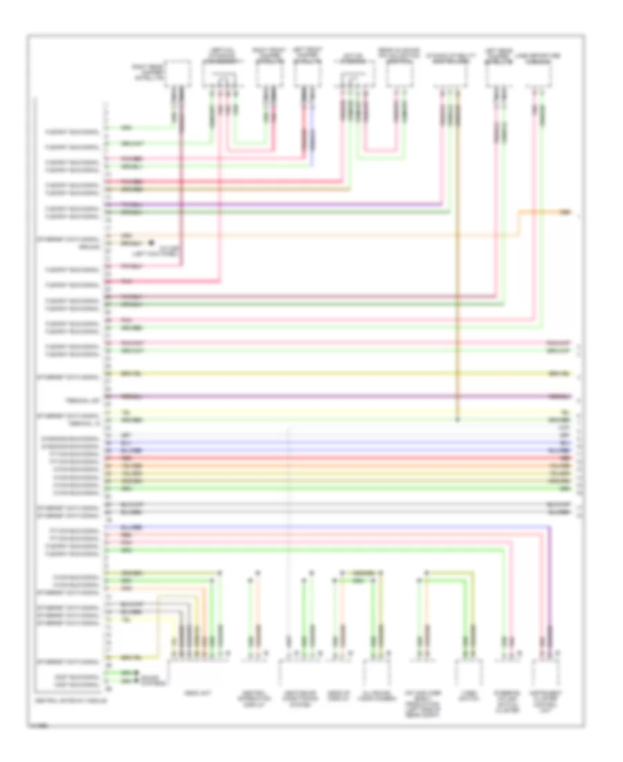
Computer Data Lines Wiring Diagram (1 of 3) for BMW 535i GT 2010
List of elements for Computer Data Lines Wiring Diagram (1 of 3) for BMW 535i GT 2010:
- Active steering
- All-round vision camera
- Central gateway module
- Central information display
- Diagnosis bus signal
- Dynamic stability control (dsc)
- Ethernet data signal
- Flexray bus signal
- Ground
- Head unit
- Head-up display
- Heating/air conditioning system
- Hifi amplifier (early production) (left side of rear compt)
- Instrument cluster control unit
- K-can bus signal
- Lane departure warning
- Left front damper satellite
- Left rear damper satellite
- Most bus signal
- Nca
- Pnk
- Pnk/red
- Pt-can bus signal
- Rear axle king pin inclination control
- Red
- Right front damper satellite
- Right rear damper satellite
- Sound systems
- Steering column switch cluster
- Terminal 15
- Terminal 30f
- Vertical dynamics management
- Video switch
- Z10 22b (left kick panel)
Computer Data Lines Wiring Diagram (2 of 3) for BMW 535i GT 2010
List of elements for Computer Data Lines Wiring Diagram (2 of 3) for BMW 535i GT 2010:
- (if equipped) high variant roof function module
- Car access system
- Controller
- Diagnosis socket
- Diagnosis socket terminating resistor
- Driver's seat module (under right side of seat)
- Electrochromic interior rear view mirror (high beam assistant w/o lane departure warning)
- Electronic ride-height control
- Footwell module
- Fuse 5a
- Hot w/ bi-stable relay energized
- Junction box (right side of dash)
- Junction box electronics
- Passenger's seat module (under passenger's seat)
- Rain/driving lights/ condensation /solar sensor
- Rear compartment air conditioning system
- Rear compartment automatic climate control
- Rear compartment controller
- Rear compartment display
- Rear compartment display 2
- Rear driver's side door seat switch cluster
- Rear driver's side power window switch
- Rear driver's side seat module
- Rear passenger's side seat module
- Red
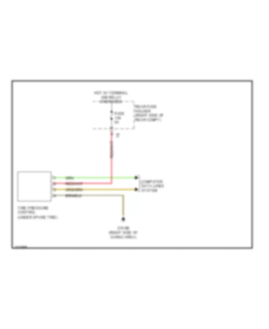
- Tire pressure control (under spare tire)
- Trailer module (under spare tire)
- Trunk lid lift
- W/ high variant roof function module
- Wiper module
- X12 1b
- X14 1b
- X200 1b
- X25 1b
- X8 1b
- Z10 22b (left kick panel)
- Z10 5b (left kick panel)
Computer Data Lines Wiring Diagram (3 of 3) for BMW 535i GT 2010
List of elements for Computer Data Lines Wiring Diagram (3 of 3) for BMW 535i GT 2010:
- (right front side of bumper) active cruise control
- Auc sensor
- Battery sensor (right side of rear compt)
- Blower output stage
- Camera based driver assistance systems
- Crash safety module
- Digital motor electronics (dme) control module (right rear engine compt)
- Driver's door seat switch cluster
- Driver's door switch block
- Driver's seat heating module
- Driver's side seat adjustment switch cluster
- Electronic transmission control (rear of transmission)
- Fuel pump control (ekps) (right rear of rear compt)
- Gear selector switch
- Integrated chassis management
- Left front footwell flap motor
- Night vision electronic module
- Parking brake control unit
- Passenger's seat heating module
- Pnk
- Radiator shutter drive unit
- Rear driver's side seat heating module
- Rear driver's side seat heating switch
- Rear passenger's side seat heating module
- Rear passenger's side seat heating switch
- Red
- Right exterior mirror
- W/o rear compartment automatic climate control
- W/o seat module
- X01001
- X12 1b
- X13 11b
- X14 1b
- X148 1b
- X28 1b
- X5 1b
COOLING FAN
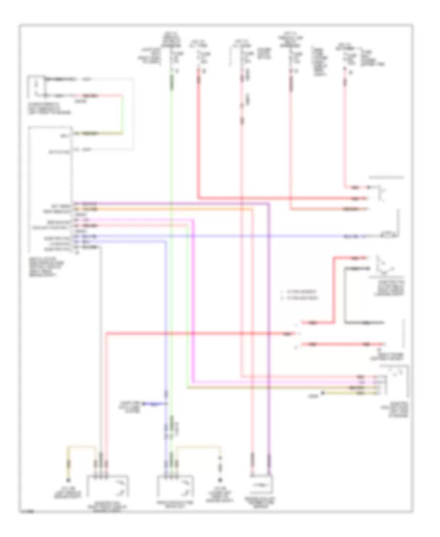
Cooling Fan Wiring Diagram for BMW 535i GT 2010
List of elements for Cooling Fan Wiring Diagram for BMW 535i GT 2010:
- Activation
- Bsd bus sig
- Characteristic map thermostat (left front of engine)
- Computer data lines system
- Coolant pump sply
- Digital motor electronics (dme) control module (right rear engine compt)
- Ect sens
- Electric coolant pump (left side of engine)
- Electric fan
- Electric fan (right front side of engine compt)
- Electric fan cutoff relay (right side of luggage compt)
- Engine coolant temperature sensor
- Front power distribution box
- Fuse 100a
- Fuse 50a
- Fuse 5a
- Fuse 60a
- Fuse 7.5a
- Fuse box (under spare tire)
- Hot at all times
- Hot w/ terminal 15n relay energized
- Hot w/ terminal 30b relay energized
- Junction box (right side of dash)
- Lin bus sig
- Nca
- Power distri- bution
- Radiator shutter drive unit
- Rear fuse holder (right side of rear compt)
- Red
- Sply
- Temp sens sig
- W/ fan 400/600w
- W/ fan 800/1000w
- X148 1b
- X60002
- X60003
- X60183
- X60571
- X62790
- X6455
- Z10 15b (left rear of engine compt)
- Z10 2b (lower left front of engine compt)
CRUISE CONTROL
Cruise Control Wiring Diagram for BMW 535i GT 2010
List of elements for Cruise Control Wiring Diagram for BMW 535i GT 2010:
- (left side of dash) brake light switch
- (rear of engine block)
- Accelerator pedal module (part of acceleration pedal assembly)
- Active cruise control (right front side of bumper)
- Brake light sw
- Central gateway module
- Computer data lines system
- Digital motor electronics (dme) control module (right rear engine compt)
- Dynamic stability control (dsc)
- Electric throttle valve (front of engine)
- Flexray bus sig
- Fuse 15a
- Fuse 5a
- Gear selector switch
- Gnd
- Hall sensor gnd
- Hall sensor sig
- Hall sensor sply
- Hot w/ terminal 15n relay energized
- Hot w/ terminal 30b relay energized
- Integrated chassis management
- Junction box (right side of dash)
- Pnk
- Power distribution system
- Pt-can bus sig
- Red
- S-can bus sig
- Steering column switch cluster
- Terminal 30, sply
- Throttle vlv activ
- Throttle vlv gnd
- Throttle vlv sig
- Throttle vlv sply
- X148 1b
- X60002
- X60005
- X6454
- Z10 2b (lower left front of engine compt)
- Z10 9b (left kick panel)
DEFOGGERS
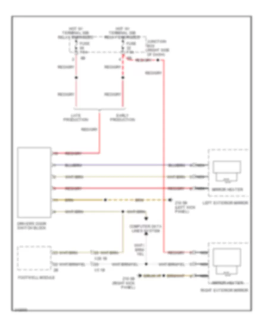
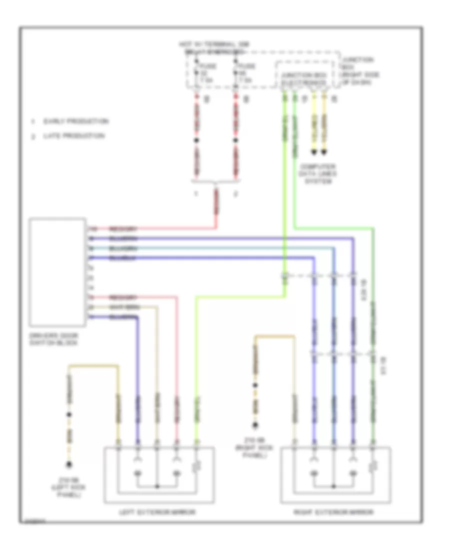
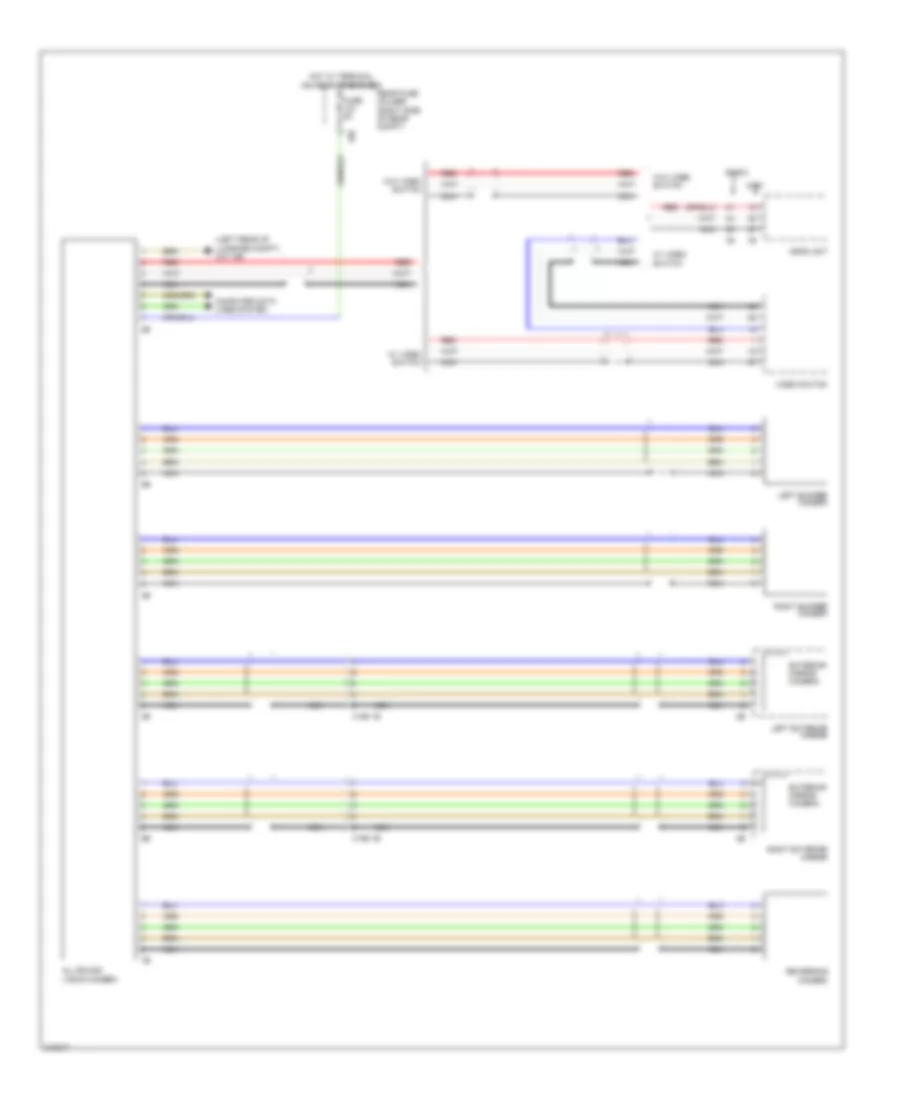
Heated Mirrors Wiring Diagram, with LIN bus Function for BMW 535i GT 2010
List of elements for Heated Mirrors Wiring Diagram, with LIN bus Function for BMW 535i GT 2010:
- Computer data lines system
- Driver's door switch block
- Early production
- Footwell module
- Fuse 7.5a
- Hot w/ terminal 30b relay energized
- Junction box (right side of dash)
- Late production
- Left exterior mirror
- Mirror heater
- Nca
- Right exterior mirror
- X28 1b
- X5 1b
- Z10 5b (left kick panel)
- Z10 6b (right kick panel)
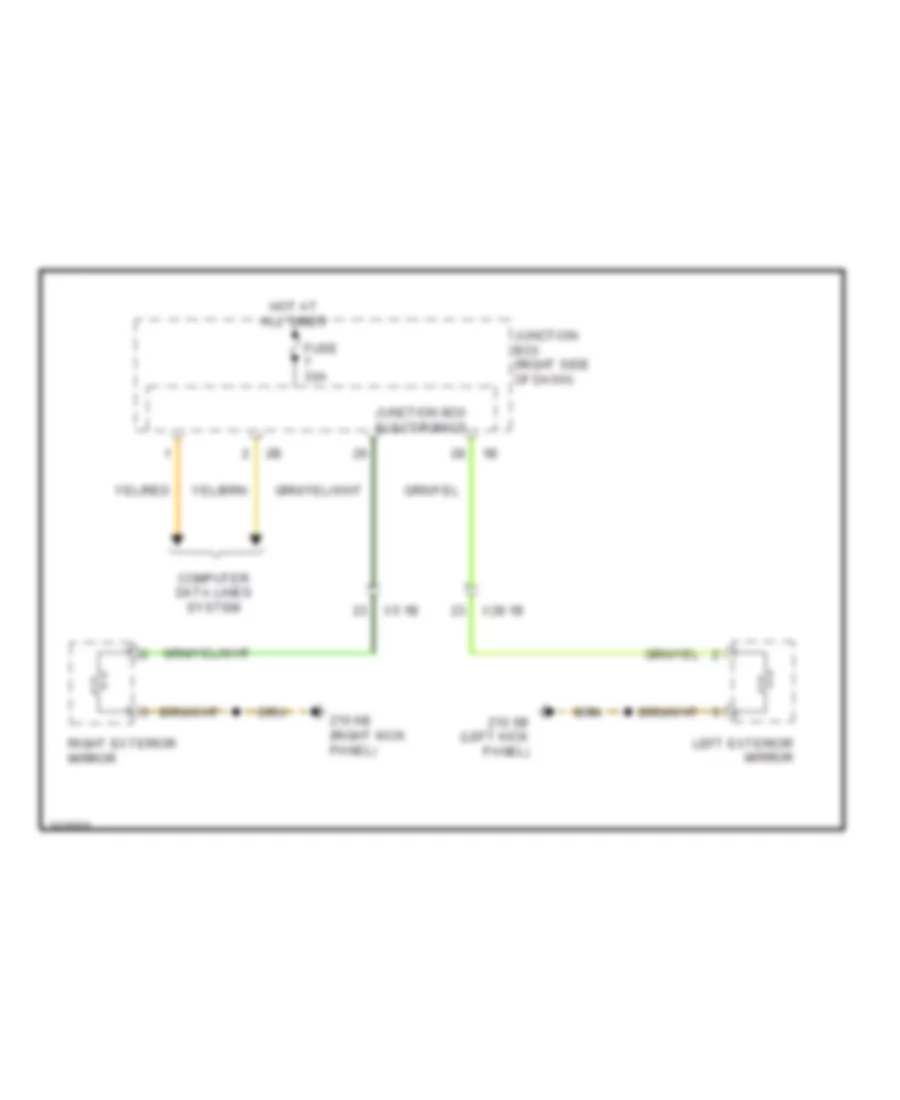
Heated Mirrors Wiring Diagram, without LIN bus Function for BMW 535i GT 2010
List of elements for Heated Mirrors Wiring Diagram, without LIN bus Function for BMW 535i GT 2010:
- Computer data lines system
- Fuse 30a
- Hot at all times
- Junction box (right side of dash)
- Junction box electronics
- Left exterior mirror
- Right exterior mirror
- X28 1b
- X5 1b
- Z10 5b (left kick panel)
- Z10 6b (right kick panel)
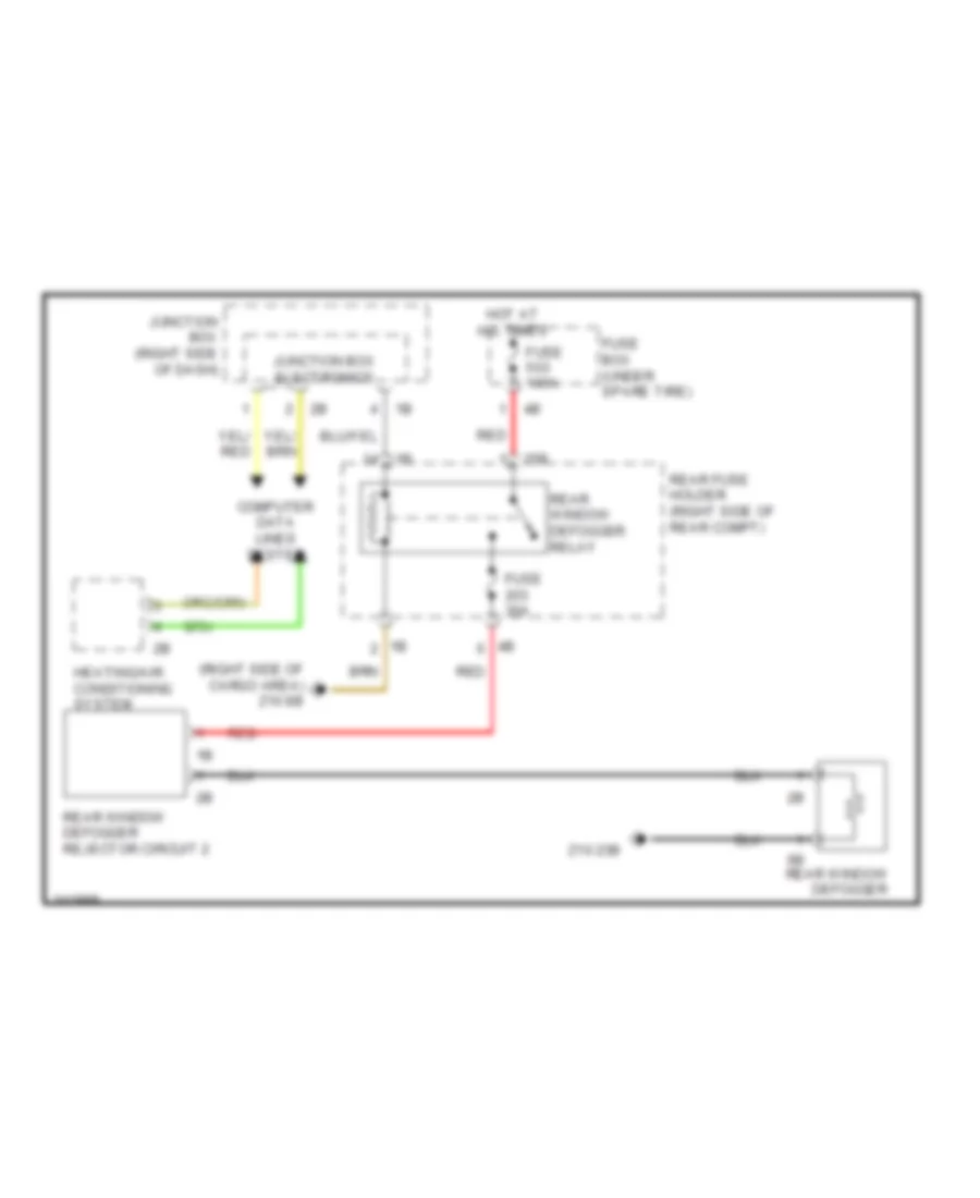
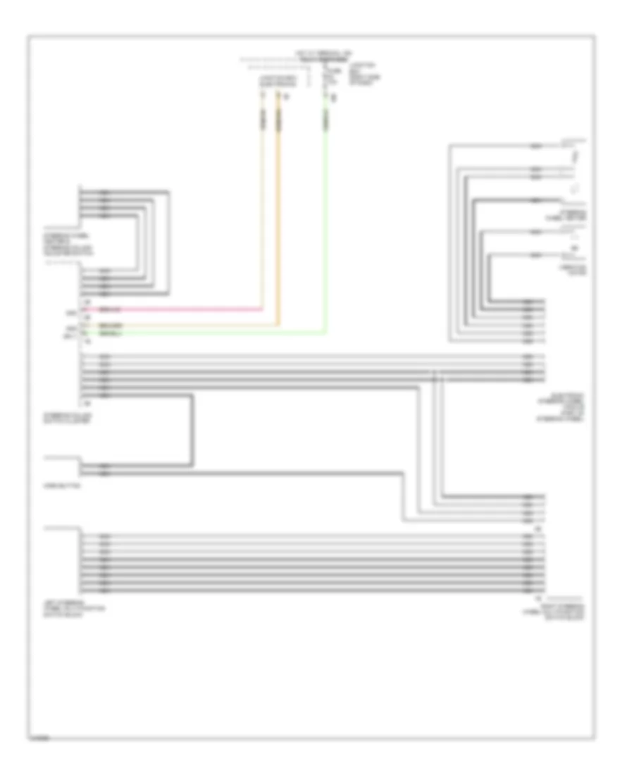
Rear Defogger Wiring Diagram for BMW 535i GT 2010
List of elements for Rear Defogger Wiring Diagram for BMW 535i GT 2010:
- (right side of cargo area) z10 8b
- 25b
- Computer data lines system
- Fuse 100a
- Fuse 30a
- Fuse box (under spare tire)
- Heating/air conditioning system
- Hot at all times
- Junction box (right side of dash)
- Junction box electronics
- Rear fuse holder (right side of rear compt)
- Rear window defogger
- Rear window defogger rejector circuit 2
- Rear window defogger relay
- Red
- Z10 23b
ELECTRONIC POWER STEERING
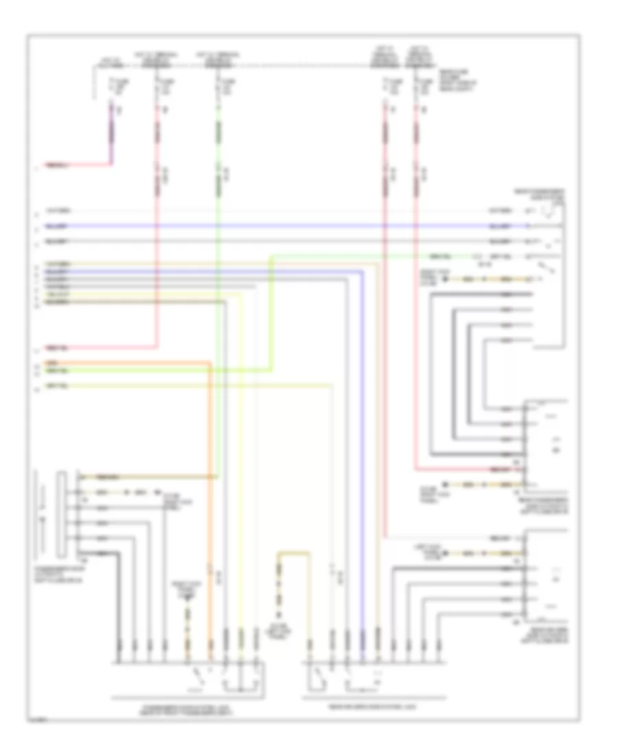
Electronic Power Steering Wiring Diagram for BMW 535i GT 2010
List of elements for Electronic Power Steering Wiring Diagram for BMW 535i GT 2010:
- (left kick panel) z10 5b
- Activation actuator
- Activation electric lock
- Active steering module (right footwell, under carpet)
- Active steering servo motor
- Actuator sig
- Actuator sply
- Central gateway module
- Eco valve
- Eco vlv
- Electric servo motor lock
- Flexray bus sig
- Fuse 40a
- Fuse 5a
- Gnd
- Hot at all times
- Hot w/ terminal 15n relay energized
- Integrated chassis management
- Junction box (right side of dash)
- Nca
- Pnk/red
- Rear axle king pin inclination control
- Servotronic valve (under vehicle, near right front wheel)
- Servotronic vlv
- Terminal 15 sply
- Terminal 30 sply
- X219 1b
- X335 1b
- X37 1b
- Z10 50b
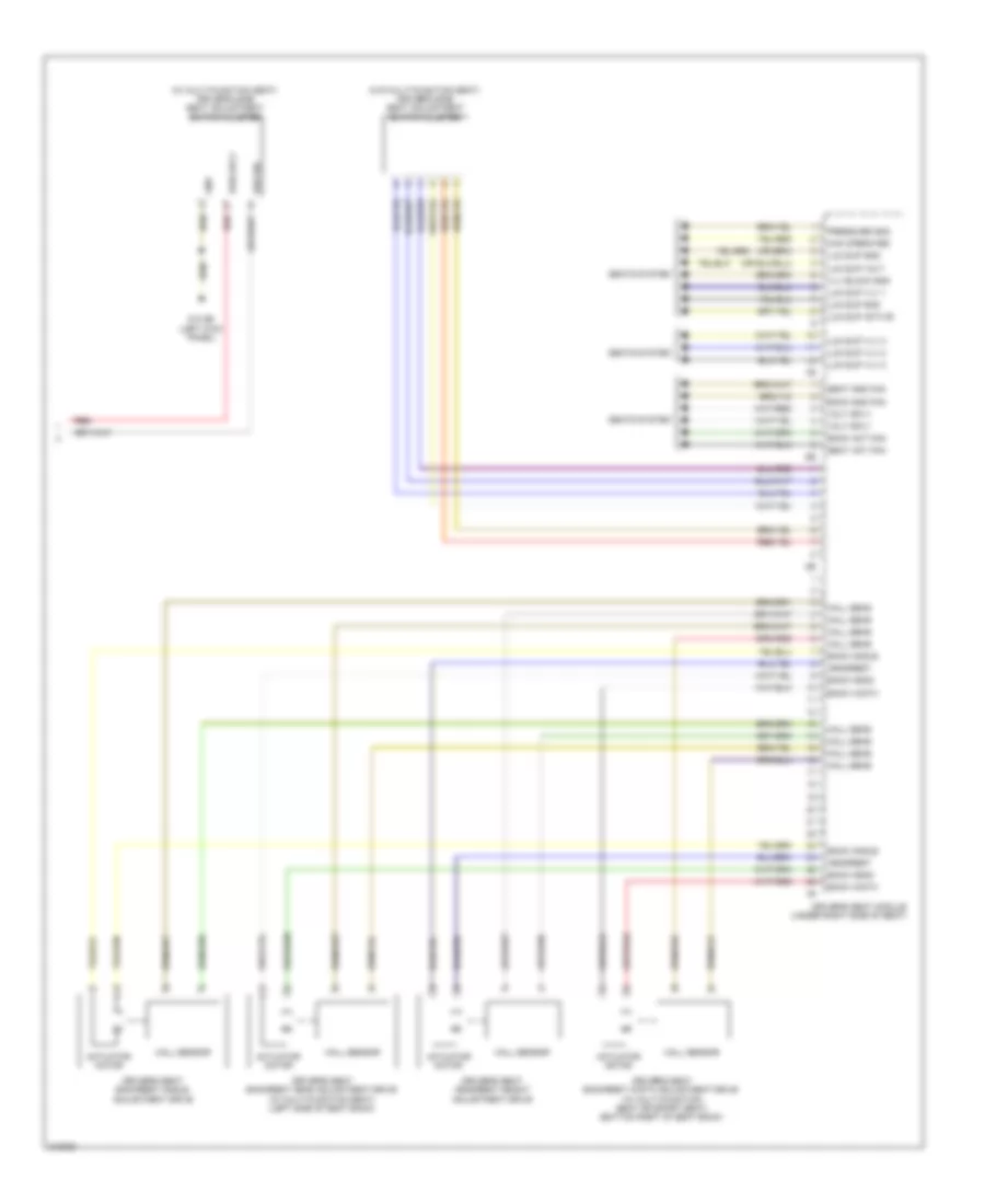
ELECTRONIC SUSPENSION
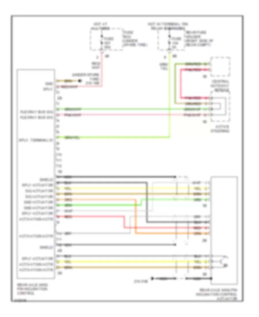
Air Suspension Wiring Diagram (1 of 2) for BMW 535i GT 2010
List of elements for Air Suspension Wiring Diagram (1 of 2) for BMW 535i GT 2010:
- (right kick panel) z10 11b
- (right rear engine compt) digital motor electronics (dme) control module
- (w/ vertical dynamics management & xenon lights)
- Center console control panel
- Central gateway module
- Computer data lines system
- Electronic power steering system
- Fuse 5a
- Hot w/ terminal 30b relay energized
- Integrated chassis management
- Junction box (right side of dash)
- Left front level sensor
- Pnk
- Right front level sensor (w/ vertical dynamics management) (behind right front wheel)
- Steering column switch cluster
- Z10 11b (right kick panel)
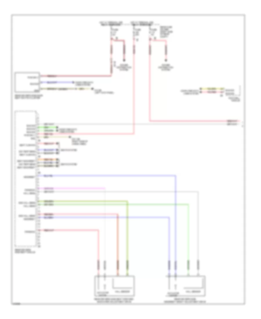
Air Suspension Wiring Diagram (2 of 2) for BMW 535i GT 2010
List of elements for Air Suspension Wiring Diagram (2 of 2) for BMW 535i GT 2010:
- Air suspension compressor relay (under spare tire)
- Computer data lines system
- Electronic ride height control (under spare tire)
- Fuse 40a
- Fuse 5a
- Hot at all times
- Hot w/ terminal 30b relay energized
- Left rear level sensor (w/ xenon lights, vertical dynamics management & electronic ride height control) (front of left rear wheel)
- M6 1b
- M6 2b
- Nca
- Rear fuse holder (right side of rear compt)
- Right rear level sensor (w/ vertical dynamics management & electronic ride height control) (front of right rear wheel)
- Y25 1b
- Z10 17b (right side of cargo area)
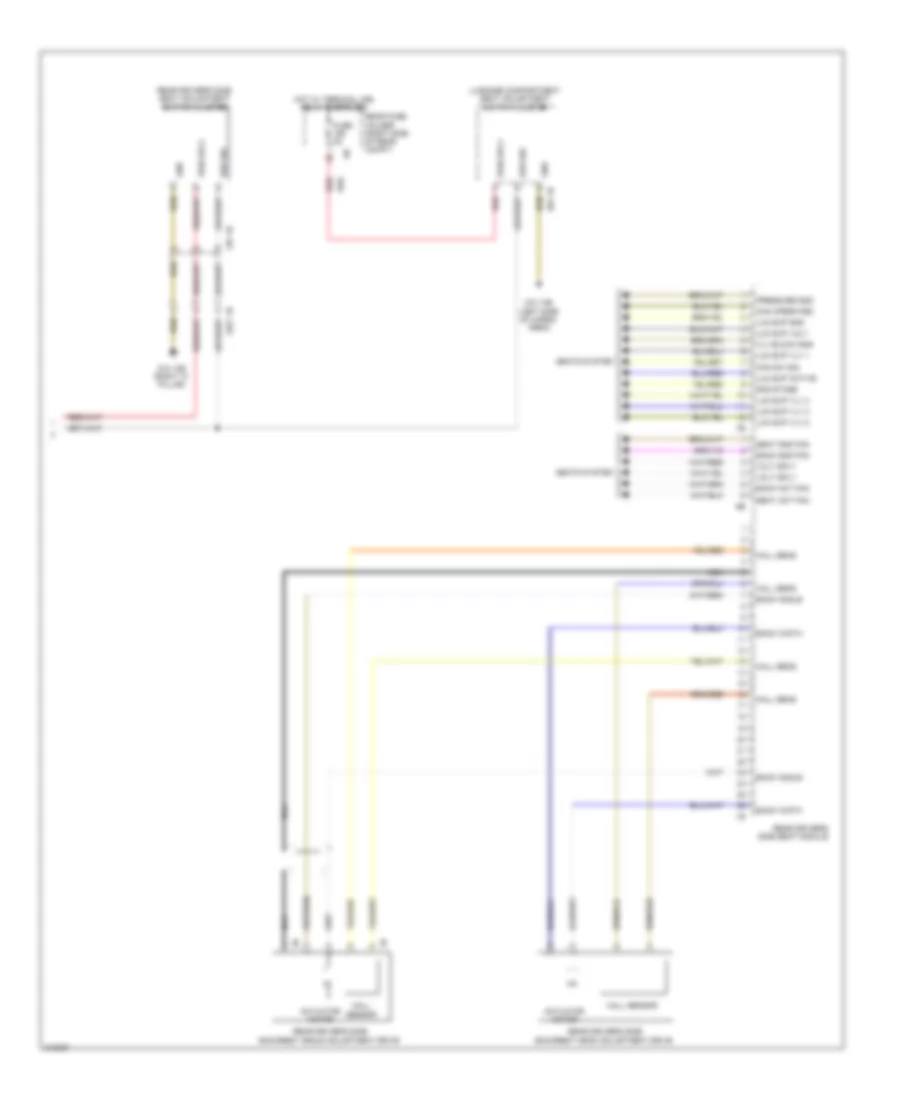
Dynamic Drive Suspension Wiring Diagram for BMW 535i GT 2010
List of elements for Dynamic Drive Suspension Wiring Diagram for BMW 535i GT 2010:
- (right kick panel)
- Central gateway module
- Dynamic drive valve block (behind right front wheel)
- Fuse 30a
- Fuse 5a
- Hot at all times
- Hot w/ terminal 15n relay energized
- Intake throttle valve
- Junction box (right side of dash)
- Left front damper satellite
- Left rear damper satellite
- Nca
- Oil level switch (right side of engine compt)
- Pnk
- Pnk/red
- Right front damper satellite
- Right rear damper satellite
- Vertical dynamic management
- X13 4b
- X158 1b
- X159 1b
- X219 1b
- Z10 14b (left side of cargo area)
- Z10 2b (lower left front of eng compt)
- Z10 2b (lower left front of engine compt)
- Z10 3b (lower right front of engine compt)
- Z10 6b
- Z10 8b (right side of cargo area)
ENGINE PERFORMANCE
3.0L TWIN TURBO
3.0L Twin Turbo, Engine Performance Wiring Diagram (1 of 5) for BMW 535i GT 2010
List of elements for 3.0L Twin Turbo, Engine Performance Wiring Diagram (1 of 5) for BMW 535i GT 2010:
- (before catalytic converter) oxygen sensor
- (right side of engine) knock sensor
- Act activation
- Bsd bus sig
- Bsd sig
- Coolant pump
- Cooling fans system
- Crankshaft position sensor (left rear side of engine)
- Digital motor electronics (dme) control module (right rear engine compt)
- Elec throttle act gnd
- Elec throttle act sig
- Electric throttle valve actuator
- Intake air temperature/ boot pressure sensor (right side of engine)
- Intake pipe pressure sensor (top of engine)
- Knock sens sig
- Nca
- Oil condition sensor (right rear of engine)
- Sens gnd
- Sens sig
- Sens sply
- Sply
- Starting/charging system
- Vlv activation
- Vlv sply
- Volume control valve
- Wastegate valve pressure converter
- X60002
3.0L Twin Turbo, Engine Performance Wiring Diagram (2 of 5) for BMW 535i GT 2010
List of elements for 3.0L Twin Turbo, Engine Performance Wiring Diagram (2 of 5) for BMW 535i GT 2010:
- (behind catalytic converter) oxygen sensor
- (top of engine) low pressure fuel sensor
- Can bus
- Characteristic map thermostat (left front of engine)
- Charcoal filter valve
- Computer data lines system
- Electric fuel pump (below right rear seat)
- Engine breather heater 1
- Exhaust camshaft sensor (rear of engine)
- Exhaust vanos solenoid valve (front of engine)
- Fuel pump
- Fuel pump control (ekps)
- Fuel tank ventilation shut-off valve
- Fuse 20a
- Fuse 5a
- Gnd
- Hot w/ terminal 30b relay energized
- Intake camshaft sensor (rear of engine)
- Intake vanos solenoid valve (front of engine)
- Junction box (right side of dash)
- Nca
- Oil pressure control valve
- Pt can
- Pwr sply
- Rear fuse holder (right side of rear compt)
- Red
- Thrust air control valve
- Wake up
- X13 10b
- X60572
- X62790
- X64553
- Z10 16b (under spare tire)
3.0L Twin Turbo, Engine Performance Wiring Diagram (3 of 5) for BMW 535i GT 2010
List of elements for 3.0L Twin Turbo, Engine Performance Wiring Diagram (3 of 5) for BMW 535i GT 2010:
- (rear of engine block) x6454
- Activation
- Car access system
- Digital motor electronics (dme) control module (right rear engine compt)
- Diverter vlv sply
- Dme main relay
- Fuse 100a
- Fuse 15a
- Fuse 20a
- Fuse 40a
- Fuse box (under spare tire)
- Gnd
- Heater sply
- Hot at all times
- Ignition & fuel injection relay
- Map activation
- Map sply
- Meter gnd
- Meter sig
- Meter sply
- Motor position sensor
- Mtr activation
- Oil press ctrl vlv sply
- Power distribution
- Pwr
- Red
- Sens gnd
- Sens sig
- Sens sply
- Valvetronic actuator motor (right side of engine)
- Valvetronic relay
- Ventilation activation
- Vlv activation
- Vlv sply
- X60003
- X60004
- X60005
- X60181
- X60182
- Z10 3b (lower right front of engine compt)
3.0L Twin Turbo, Engine Performance Wiring Diagram (4 of 5) for BMW 535i GT 2010
List of elements for 3.0L Twin Turbo, Engine Performance Wiring Diagram (4 of 5) for BMW 535i GT 2010:
- (right center side of engine) ignition coil 3
- (right center side of engine) ignition coil 4
- (right front side of engine) ignition coil 1
- (right front side of engine) ignition coil 2
- (right rear side of engine) ignition coil 5
- (right rear side of engine) ignition coil 6
- Engine coolant temperature sensor
- Engine oil pressure sensor
- Engine oil temperature sensor
- Hot film mass air flow sensor (right front side of engine)
- Nca
- Plug spark
- Rail pressure sensor (on right cylinder head fuel rail)
- Spark plug
- X60574
- X6170
- X6171
- X6172
3.0L Twin Turbo, Engine Performance Wiring Diagram (5 of 5) for BMW 535i GT 2010
List of elements for 3.0L Twin Turbo, Engine Performance Wiring Diagram (5 of 5) for BMW 535i GT 2010:
- (top of engine) fuel injectors
- Accelerator pedal module (part of acceleration pedal bracket)
- Anti-theft system
- Battery sensor (right side of rear compt)
- Car bus sig
- Computer data lines system
- Cooling fans system
- Cut-out relay
- Diagnosis socket
- Digital motor electronics (dme) control module (right rear engine compt)
- Electric fan
- Electronic suspension system
- Flexray bus sig
- Fuel inj 1 activation
- Fuel inj 1 sply
- Fuel inj 2 activation
- Fuel inj 2 sply
- Fuel inj 3 activation
- Fuel inj 3 sply
- Fuel inj 4 activation
- Fuel inj 4 sply
- Fuel inj 5 activation
- Fuel inj 5 sply
- Fuel inj 6 activation
- Fuel inj 6 sply
- Fuel tank leakage
- Fuel tank leakage diagnostic module (behind right rear wheel)
- Fuse 15a
- Fuse 5a
- Hal sens sig
- Hall sens gnd
- Hall sens sply
- Hot w/ terminal 15n relay energized
- Hot w/ terminal 30b relay energized
- Ign coil 1 activation
- Ign coil 1 sply
- Ign coil 2 activation
- Ign coil 2 sply
- Ign coil 3 activation
- Ign coil 3 sply
- Ign coil 4 activation
- Ign coil 4 sply
- Ign coil 5 activation
- Ign coil 5 sply
- Ign coil 6 activation
- Ign coil 6 sply
- Junction box (right side of dash)
- Lin bus sig
- Nca
- Pnk
- Power distribution system
- Pt-can bus sig
- Radiator shutter drive unit
- Rear fuse holder (right side of rear compt)
- Red
- Start sig
- Starting/charging system
- Term 15 sply
- Term 15 wake up sig
- Term 30 sply
- X148 1b
- X60006
- Z10 2b (lower left front of engine compt)
EXTERIOR LIGHTS
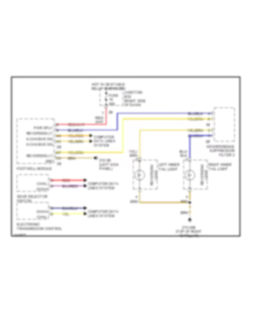
Backup Lamps Wiring Diagram for BMW 535i GT 2010
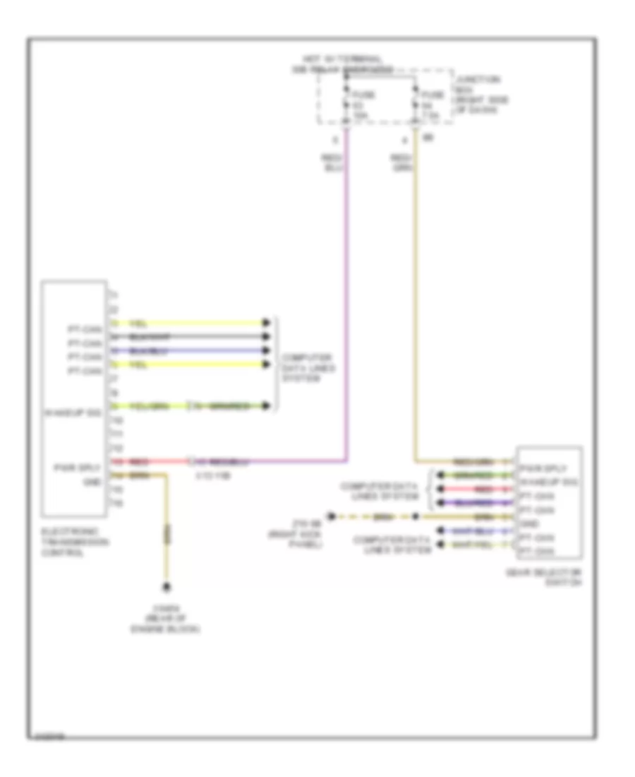
List of elements for Backup Lamps Wiring Diagram for BMW 535i GT 2010:
- Can-h
- Can-l
- Computer data lines system
- Electronic transmission control
- Footwell module
- Fuse 40a
- Gear selector switch
- Gnd
- Hot w/ bi-stable relay energized
- Interference suppressor filter 2
- Junction box (right side of dash)
- K-can bus sig
- Left inner tail light
- Light reversing
- Pwr sply
- Red
- Reversing lt
- Right inner tail light
- Z10 20b (top of right "c" pillar)
- Z10 5b (left kick panel)
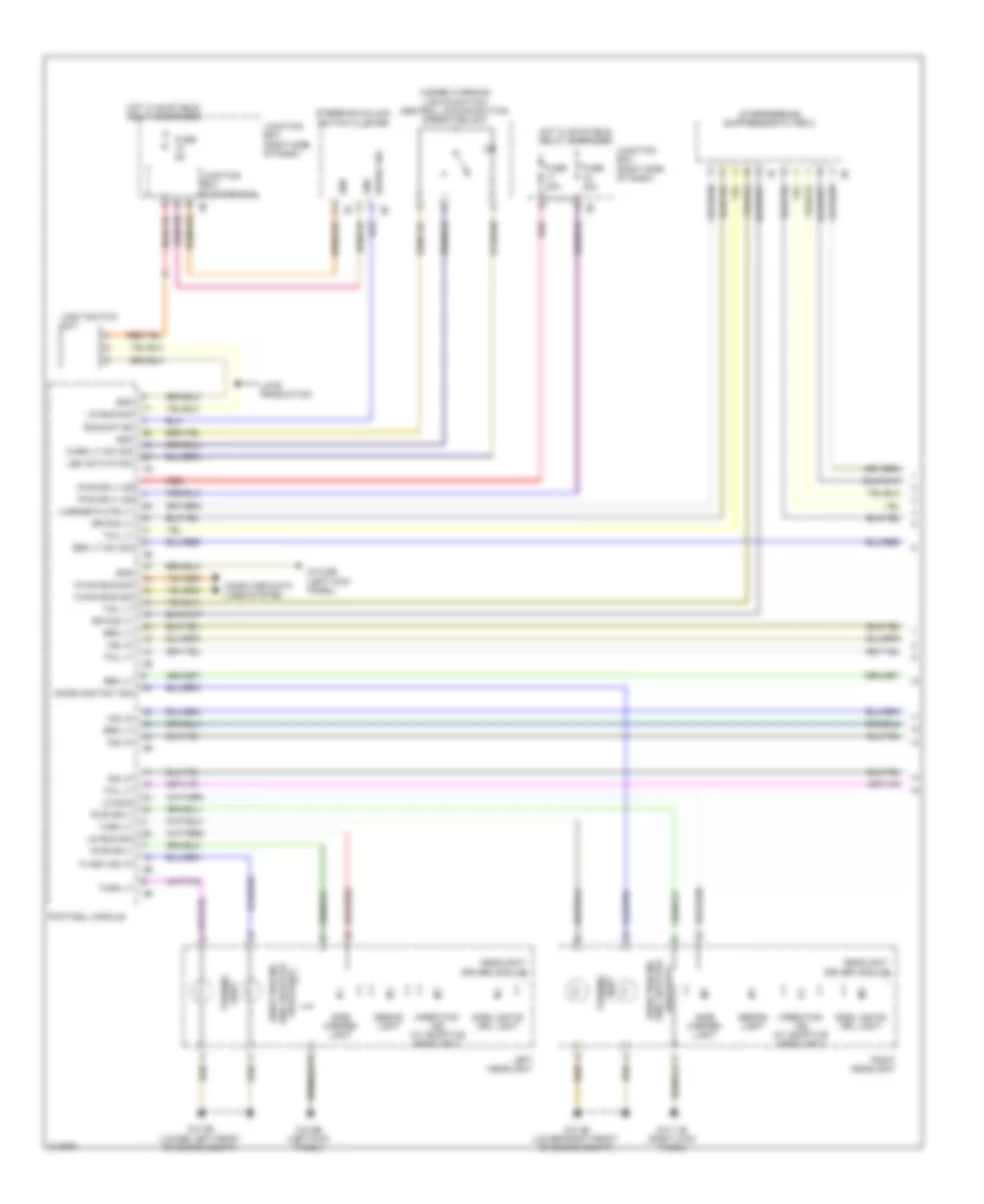
Exterior Lamps Wiring Diagram (1 of 2) for BMW 535i GT 2010
List of elements for Exterior Lamps Wiring Diagram (1 of 2) for BMW 535i GT 2010:
- (w/o adaptive headlight)
- Backup ind
- Brk lt
- Brk lt sw sig
- Computer data lines system
- Design light
- Direction ind
- Direction ind (w/ adaptive headlight)
- Direction ind (w/o adaptive headlight)
- Door contacy sig
- Flash ind lp
- Footwell module
- Fuse 30a
- Fuse 5a
- Gnd
- Hazard warning lights switch/ central locking button operating unit
- Headlight driver module
- Hot w/ bi-stable relay energized
- Ind lp
- Interference suppressor filter 2
- Junction box (right side of dash)
- Junction box electronics
- K-can bus sig
- Late production
- Led activation
- Left headlight
- License plate lt
- Light
- Light switch unit
- Light turning
- Lin bus
- Lin bus sig
- Pwr sply
- Pwr sply 30f
- Red
- Right headlight
- Rr fog lt
- Serial sig
- Side lights/ drl light
- Side marker light
- Steering column switch cluster
- Tail lt
- Turn lt
- Turning
- Warn lt sw sig
- Z10 11b (right kick panel)
- Z10 22b (left kick panel)
- Z10 2b (lower left front of engine compt)
- Z10 3b (lower right front of engine compt)
- Z10 9b (left kick panel)
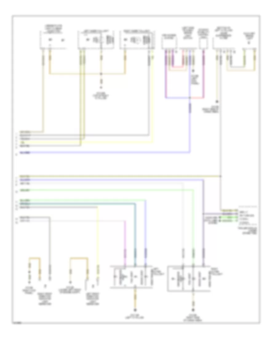
Exterior Lamps Wiring Diagram (2 of 2) for BMW 535i GT 2010
List of elements for Exterior Lamps Wiring Diagram (2 of 2) for BMW 535i GT 2010:
- (bottom of left "c" pillar) noise suppressor filter
- (left side of dash) brake light switch
- Auxiliary brake light
- Brake light
- Brk lt
- Car access system
- Computer data lines system
- Direction ind
- Dynamic brake light
- Dynamic stability control (dsc)
- K can-h
- K can-l
- Left front direction indicator light repeater
- Left inner taillight
- Left outer taillight
- License plate light w/ rear lid button
- Light side marker
- Light tail
- Rh turn sig
- Right front direction indicator light repeater
- Right inner taillight
- Right outer taillight
- Side marker light
- Tail light
- Trailer module (under spare tire)
- Z10 14b (left "c" pillar)
- Z10 20b (top of right "c" pillar)
- Z10 2b (lower left front of engine compt)
- Z10 6b (right kick panel)
- Z10 8b (right side of cargo area)
- Z10 9b (left kick panel)
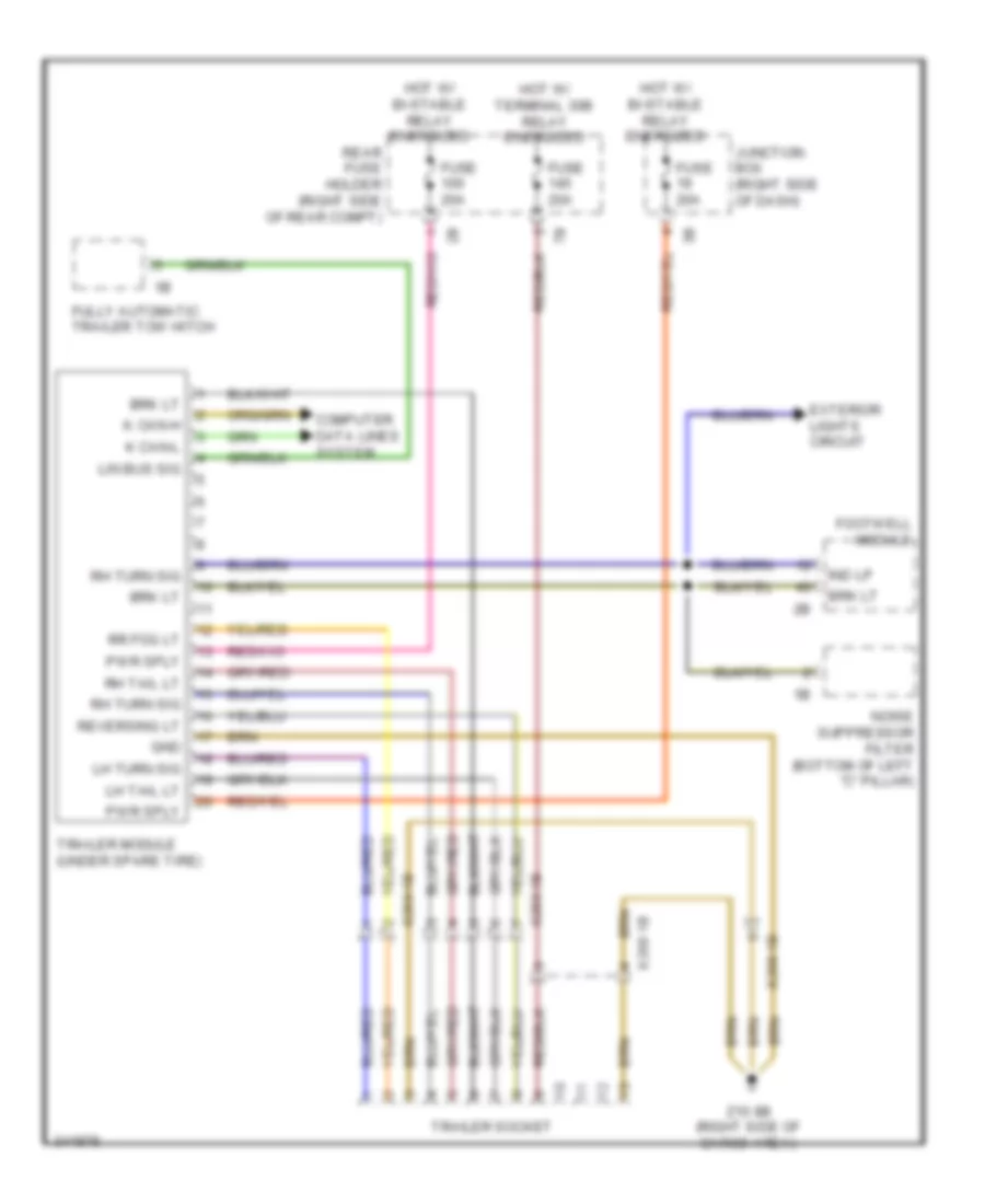
Trailer Tow Wiring Diagram for BMW 535i GT 2010
List of elements for Trailer Tow Wiring Diagram for BMW 535i GT 2010:
- Brk lt
- Computer data lines system
- Exterior lights circuit
- Footwell module
- Fully automatic trailer tow hitch
- Fuse 20a
- Gnd
- Hot w/ bi-stable relay energized
- Hot w/ terminal 30b relay energized
- Ind lp
- Junction box (right side of dash)
- K can-h
- K can-l
- Lh tail lt
- Lh turn sig
- Lin bus sig
- Noise suppressor filter (bottom of left "c" pillar)
- Pwr sply
- Rear fuse holder (right side of rear compt)
- Reversing lt
- Rh tail lt
- Rh turn sig
- Rr fog lt
- Trailer module (under spare tire)
- Trailer socket
- X268 1b
- X269 1b
- Z10 8b (right side of cargo area)
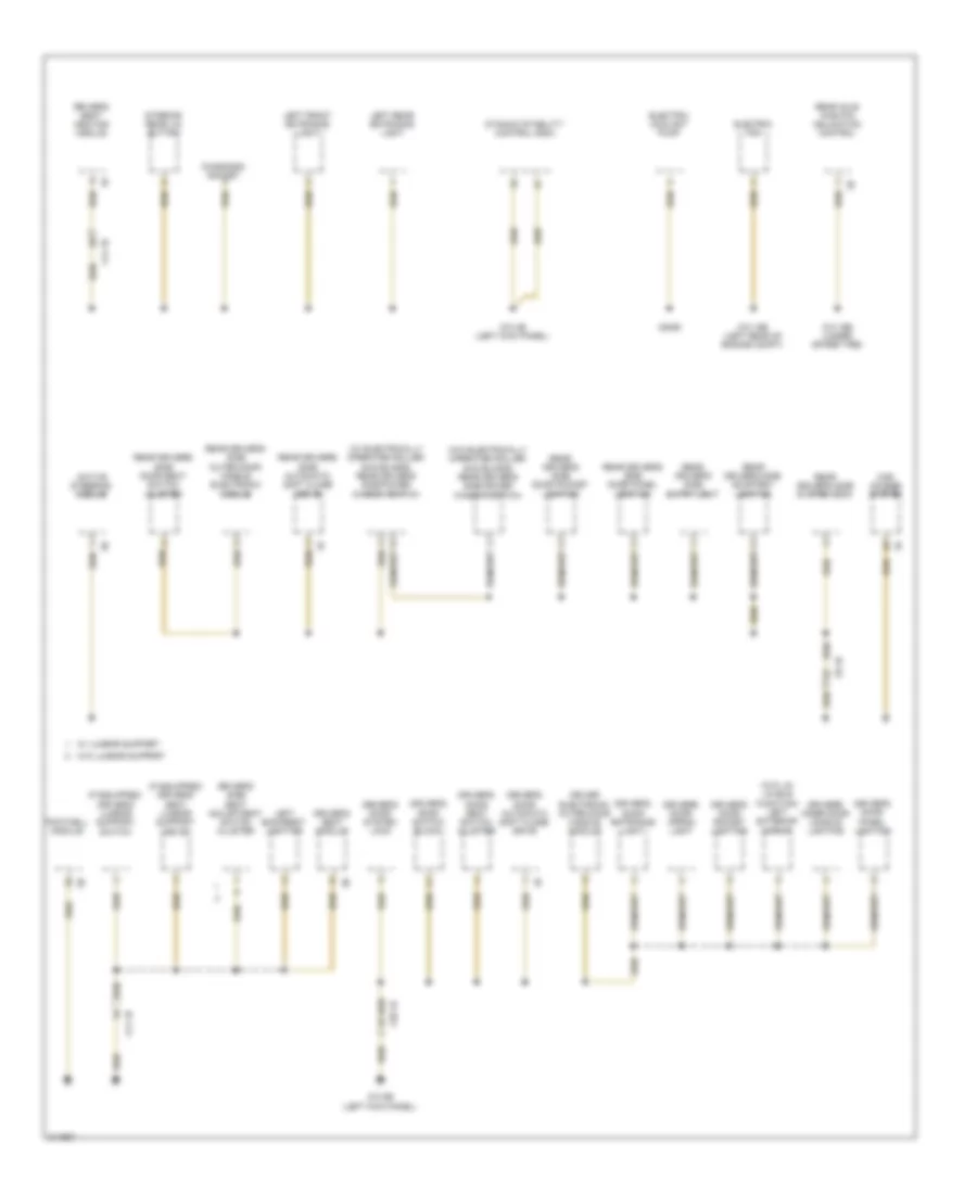
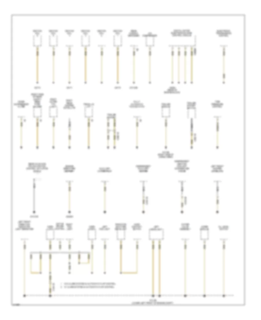
GROUND DISTRIBUTION
Ground Distribution Wiring Diagram (1 of 5) for BMW 535i GT 2010
List of elements for Ground Distribution Wiring Diagram (1 of 5) for BMW 535i GT 2010:
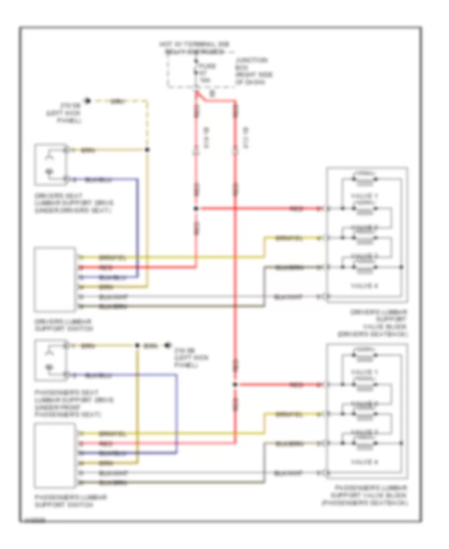
- (if equipped) driver's lumbar support switch
- (if equipped) driver's seat lumbar support drive
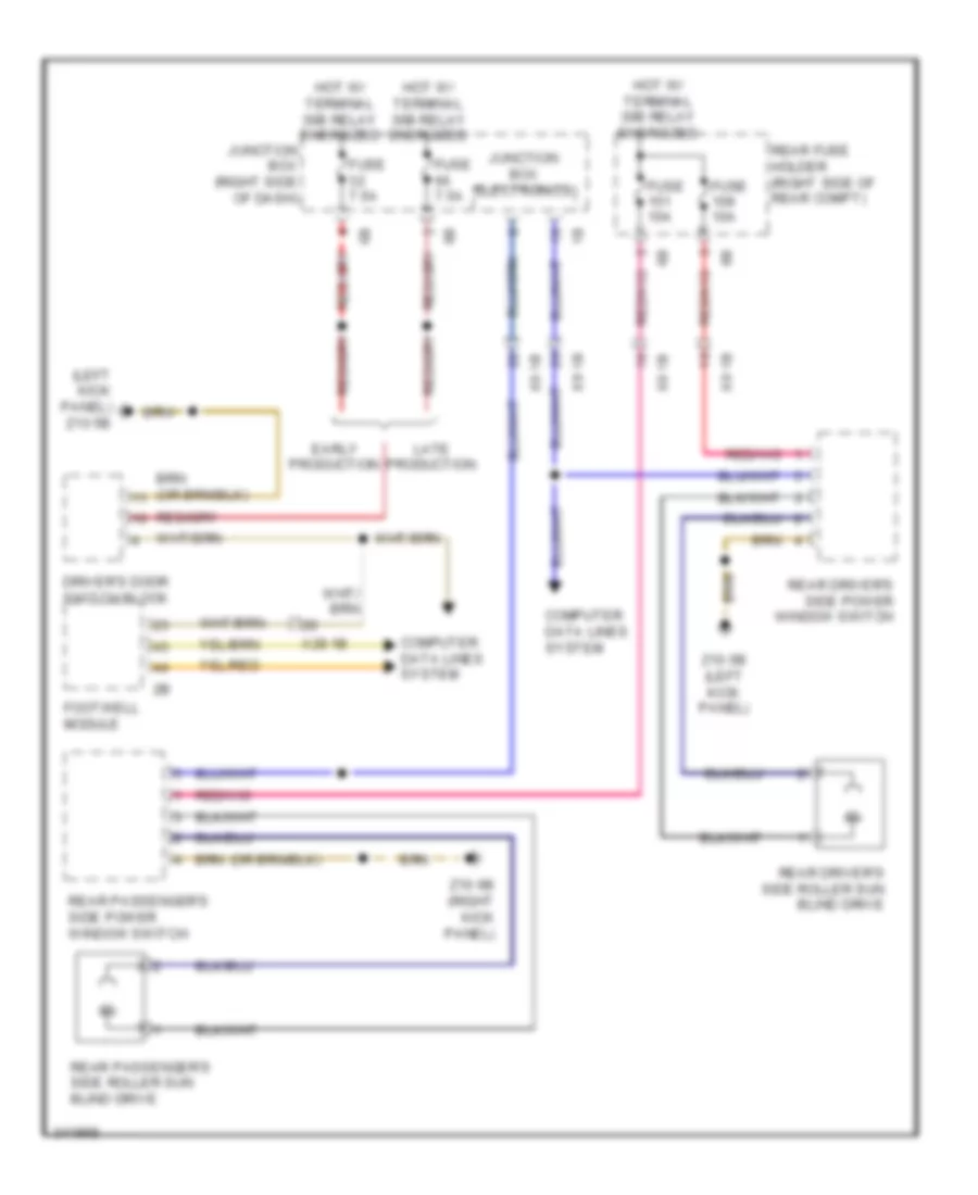
- (w/ electrically operated roller sun blinds) rear driver's side power window switch
- (w/o electrically operated roller sun blinds) rear driver's side power window switch
- (w/o lin lin bus function) left exterior mirror
- Active steering module
- Car access system
- Diagnosis socket
- Driver electronic outer door handle module
- Driver's door apron light
- Driver's door automatic soft close drive
- Driver's door entrance light
- Driver's door panel lighting
- Driver's door pocket lighting
- Driver's door seat switch cluster
- Driver's door switch block
- Driver's door system lock
- Driver's inner door handle lighting
- Driver's seat heating module
- Driver's seat module
- Driver's side seat adjustment switch cluster
- Dynamic stability control (dsc)
- Electric coolant pump
- Electric fan
- Footwell module
- Interior rear lid button
- Left backrest lighting
- Left front entrance light
- Left rear entrance light
- Rear axle king pin inclination control
- Rear driver's side automatic soft close drive
- Rear driver's side courtesy lighting
- Rear driver's side door panel lighting
- Rear driver's side door pocket lighting
- Rear driver's side door seat switch cluster
- Rear driver's side entry light
- Rear driver's side outer door handle electronic module
- Rear driver's side system lock
- W/ lumbar support
- W/o lumbar support
- X14 1b
- X28 1b
- X6455
- X8 1b
- Z10 15b (left rear of engine compt)
- Z10 16b (under spare tire)
- Z10 4b (left kick panel)
- Z10 5b (left kick panel)
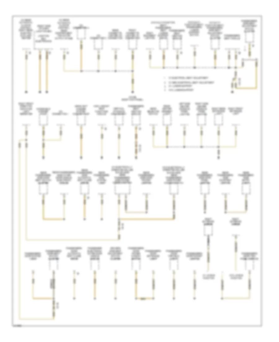
Ground Distribution Wiring Diagram (2 of 5) for BMW 535i GT 2010
List of elements for Ground Distribution Wiring Diagram (2 of 5) for BMW 535i GT 2010:
- (right side of dash) junction box
- (w/ electrically operated roller sun blinds) rear passenger's side power window switch
- (w/ multi- function seat) passenger's side seat adjustment switch cluster
- (w/ rear automatic climate control) rear compartment fan motor output stage
- (w/ rear automatic climate control) right rear electric auxiliary heater
- (w/o electrically operated roller sun blinds) rear passenger's side power window switch
- (w/o multi- function seat) passenger's lumbar support switch
- (w/o multi-function seat) passenger's seat lumbar support drive
- 12v connection 1
- 12v connection 3
- 12v connection 4
- Driver's side seat adjustment switch cluster
- Front center armrest light
- Front cigarette lighter 12v connection
- Gear selector switch
- Headlight washer system washer pump
- High variant roof functions module
- Junction box electronics
- Left side center console panel lighting
- Nca
- Passenger electronic outer door handle module
- Passenger's door automatic soft close drive
- Passenger's door entrance light
- Passenger's door far field light
- Passenger's door pocket lighting
- Passenger's door power window switch
- Passenger's door seat switch cluster
- Passenger's door system lock
- Passenger's door trim panel lighting
- Passenger's seat heating module
- Passenger's seat module
- Passenger's side seat adjustment switch cluster
- Rear cigarette lighter 12v connection
- Rear passenger's side automatic soft close drive
- Rear passenger's side courtesy lighting
- Rear passenger's side door panel lighting
- Rear passenger's side door pocket lighting
- Rear passenger's side door seat switch cluster
- Rear passenger's side entry light
- Rear passenger's side outer door handle electronic module
- Rear passenger's side system lock
- Right backrest lighting
- Right exterior mirror
- Right front direction indicator light repeater
- Right front entrance light
- Right rear entrance light
- Right side center console panel lighting
- Vertical dynamics management
- W/ electrical seat adjustment
- W/ lin bus function
- W/ lumbar support
- W/ semi electrical seat adjustment
- W/o lin bus function
- W/o lumbar support
- Windshield washer pump
- X12 1b
- X5 1b
- X9 1b
- Z10 6b (right kick panel)
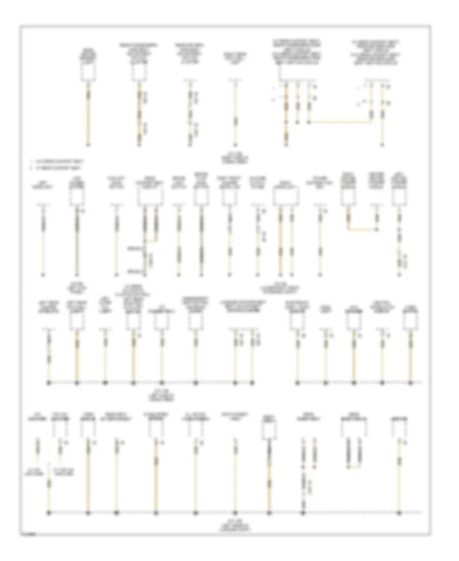
Ground Distribution Wiring Diagram (3 of 5) for BMW 535i GT 2010
List of elements for Ground Distribution Wiring Diagram (3 of 5) for BMW 535i GT 2010:
- (if equipped) combox
- (w/ rear automatic climate control) left rear electric auxiliary heater
- (w/ rear comfort seat) rear driver's side seat module (w/o rear comfort seat) rear driver's side seat heating module
- (w/ rear comfort seat) rear passenger's side seat module (w/o rear comfort seat) rear passenger's side seat heating module
- 12v connection 2
- All round vision camera
- Blower output stage
- Brake fluid level switch
- Brake light switch
- Car access system
- Center heated washer nozzle
- Central information display
- Coolant level switch
- Dvd changer
- Eject box
- Electronic night vision module
- Head unit
- Hifi amplifier
- Independent heating fuel metering pump
- Infotainment fan
- Left headlight
- Left heated washer nozzle
- Left outer tail light
- Left rear damper satellite
- Left rear footwell light
- Luggage compartment seat adjustment switch cluster
- N2 1b
- Nca
- Power distribution box
- Rear center armrest light
- Rear compartment display
- Rear driver's side seat adjustment switch cluster
- Rear eject box
- Rear eject box 2
- Rear passenger's side seat adjustment switch cluster
- Rear seat entertainment
- Right front damper satellite
- Right headlight
- Right heated washer nozzle
- Right rear footwell light
- S91 1b
- S92 1b
- Top hifi amplifier
- Usb hub
- Video module
- Video switch
- W/ hifi amplifier
- W/ rear comfort seat
- W/ top hifi amplifier
- W/o rear comfort seat
- X10 1b
- X167 1b
- X217 1b
- X230 1b
- X257 1b
- X81 1b
- X82 1b
- Z10 12b (left rear of luggage compt)
- Z10 13b (right side of cargo area)
- Z10 14b (left side of cargo area)
- Z10 3b (lower right front of engine compt)
- Z10 9b (left kick panel)
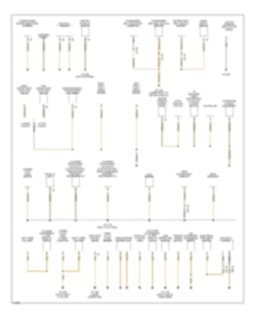
Ground Distribution Wiring Diagram (4 of 5) for BMW 535i GT 2010
List of elements for Ground Distribution Wiring Diagram (4 of 5) for BMW 535i GT 2010:
- (if equipped) rear compartment automatic climate control
- (w/ noise suppressor filter) rear lid lock 2
- (w/o noise suppressor filter) rear lid lock 2
- (w/o rear compartment automatic climate control)
- Active steering servo motor shield
- Air suspension compressor relay
- Auc sensor
- Basic variant roof functions module
- Camera-based driver assistance systems
- Center console control panel
- Central gateway module
- Controller
- Crash safety module
- Diagnosis socket
- Driver's seat belt buckle contact
- Electrochromic interior rear view mirror
- Electronic ride height control
- Footwell module
- Fuel pump control (ekps)
- High variant roof functions module
- Hotel position switch
- Integrated chassis management
- Lane departure warning
- Left front vanity mirror switch
- Left inner tail light
- License plate light w/ rear lid button
- M6 1b
- Nca
- Parking brake button
- Parking brake control unit
- Passenger's seat belt buckle contact
- Passenger's seat occupancy detection
- Rear compartment display 2
- Rear driver's side seat heating switch
- Rear passenger's side seat heating switch
- Right front vanity mirror switch
- Right headlight
- Right inner tail light
- Siren & tilt alarm sensor
- Trunk lid lift
- Trunk lid/ tailgate lock
- W/ basic variant
- W/ high variant
- Washer fluid level switch
- X12 1b
- X12 2b
- X14 1b
- X231 1b
- Y25 1b
- Z10 10b (under front of center console)
- Z10 11b (right kick panel)
- Z10 16b (under spare tire)
- Z10 17b (right side of cargo area)
- Z10 20b (top of right "c" pillar)
- Z10 22b (left kick panel)
- Z10 50b
Ground Distribution Wiring Diagram (5 of 5) for BMW 535i GT 2010
List of elements for Ground Distribution Wiring Diagram (5 of 5) for BMW 535i GT 2010:
- (right side of rear compt) rear fuse holder
- A/c compressor
- Active cruise control
- Auxiliary water pump
- Digital motor electronics (dme) control module
- Electronic transmission control
- Engine breather heater 1
- Fully automatic towing hitch
- Hood contact switch
- Horn (high)
- Horn (low)
- Ignition coil
- Independent auxiliary heater
- Independent heating coolant changeover valve
- Left fog light
- Left front damper satellite
- Left front direction indicator light repeater
- Left headlight
- Nca
- Noise suppressor filter
- Oil level switch
- Radiator shutter drive unit
- Rear axle king pin inclination control actuator shield
- Rear window defogger
- Right fog light
- Right outer tail light
- Right rear damper satellite
- Tire pressure control
- Trailer module
- Trailer socket
- Trailer socket switch
- Trunk lid lift
- W/ alarm system & automatic flap control
- W/o alarm system & automatic flap control
- Water valve assembly
- Wiper module
- X149 1b
- X218 1b
- X218 2b
- X268 1b
- X269 1b
- X60005
- X6170
- X6171
- X6172
- X6454 (rear of engine block)
- X64553
- Z10 23b
- Z10 2b (lower left front of engine compt)
- Z10 51b
- Z10 8b (right side of cargo area)
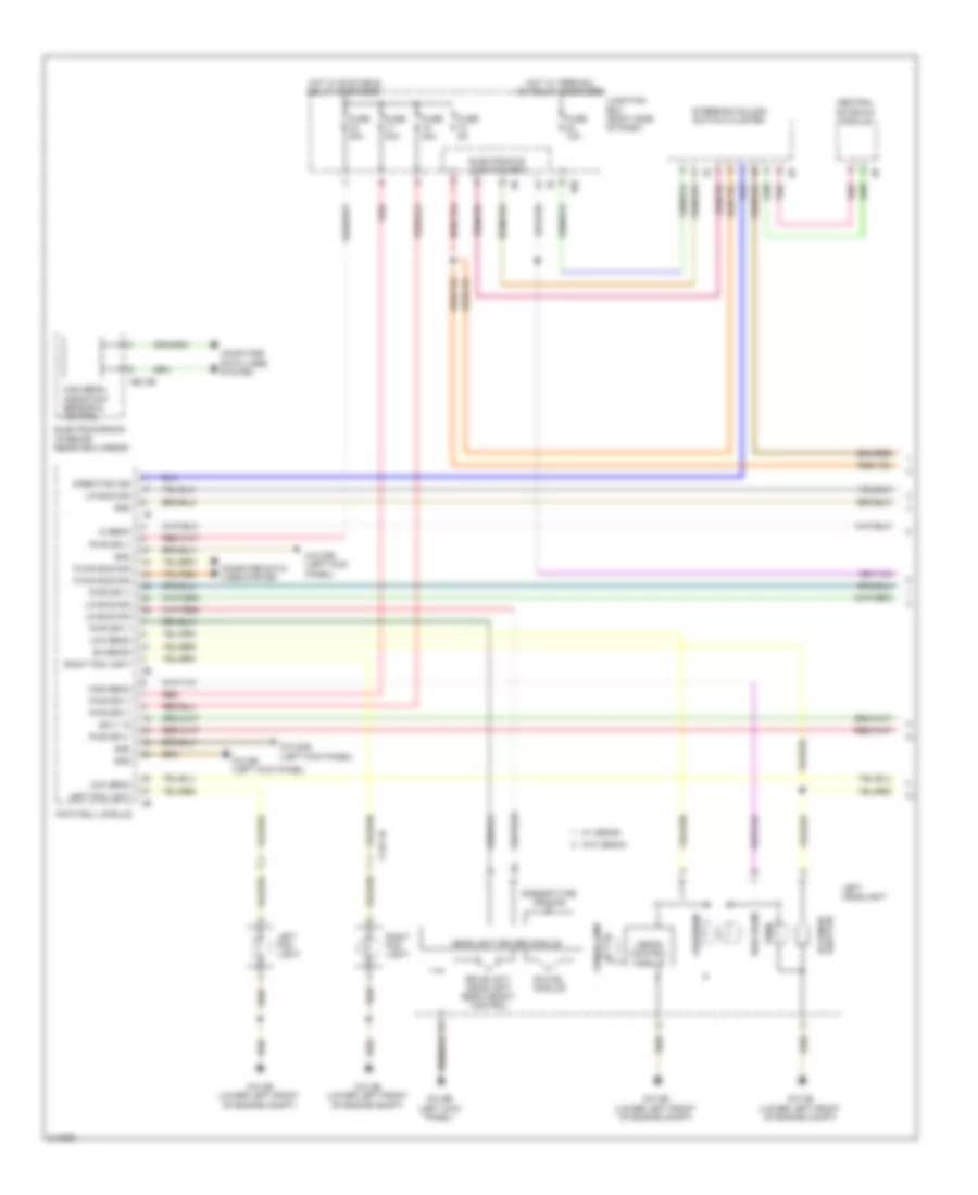
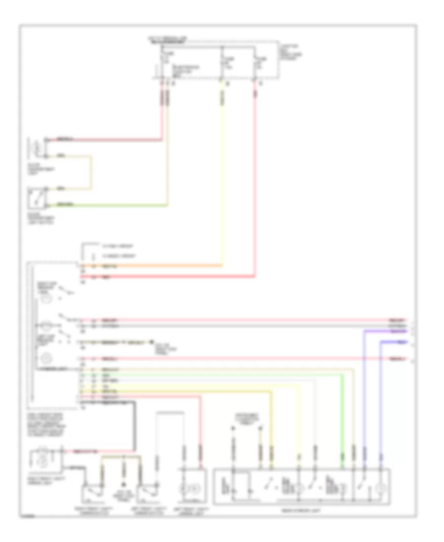
HEADLIGHTS
Headlights Wiring Diagram (1 of 2) for BMW 535i GT 2010
List of elements for Headlights Wiring Diagram (1 of 2) for BMW 535i GT 2010:
- 10b
- A60 2b
- Bi-xenon
- Central gateway module
- Computer data lines system
- Direction ind
- Drive unit, headlight beam height control
- Electrochromic interior rearview mirror
- Electronics junction box
- Footwell module
- Fuse 10a
- Fuse 30a
- Fuse 40a
- Fuse 5a
- Gnd
- Headlight driver module
- Hi beam
- High beam
- High beam assistant sensor & control
- Hot w/ bi-stable relay energized
- Hot w/ terminal 15n relay energized
- Junction box (right side of dash)
- K-can bus sig
- Left fog light
- Left headlight
- Lin bus sig
- Low beam
- Pnk
- Pwr sply
- Red
- Right fog light
- Shutter bi-xenon
- Side/daytime driving
- Sply 15
- Steering column switch cluster
- Swivel module
- Turn
- W/ xenon
- W/o xenon
- X149 1b
- Xenon control module
- Xenon lamp
- Z10 22b (left kick panel)
- Z10 2b (lower left front of engine compt)
- Z10 5b (left kick panel)
- Z10 9b (left kick panel)
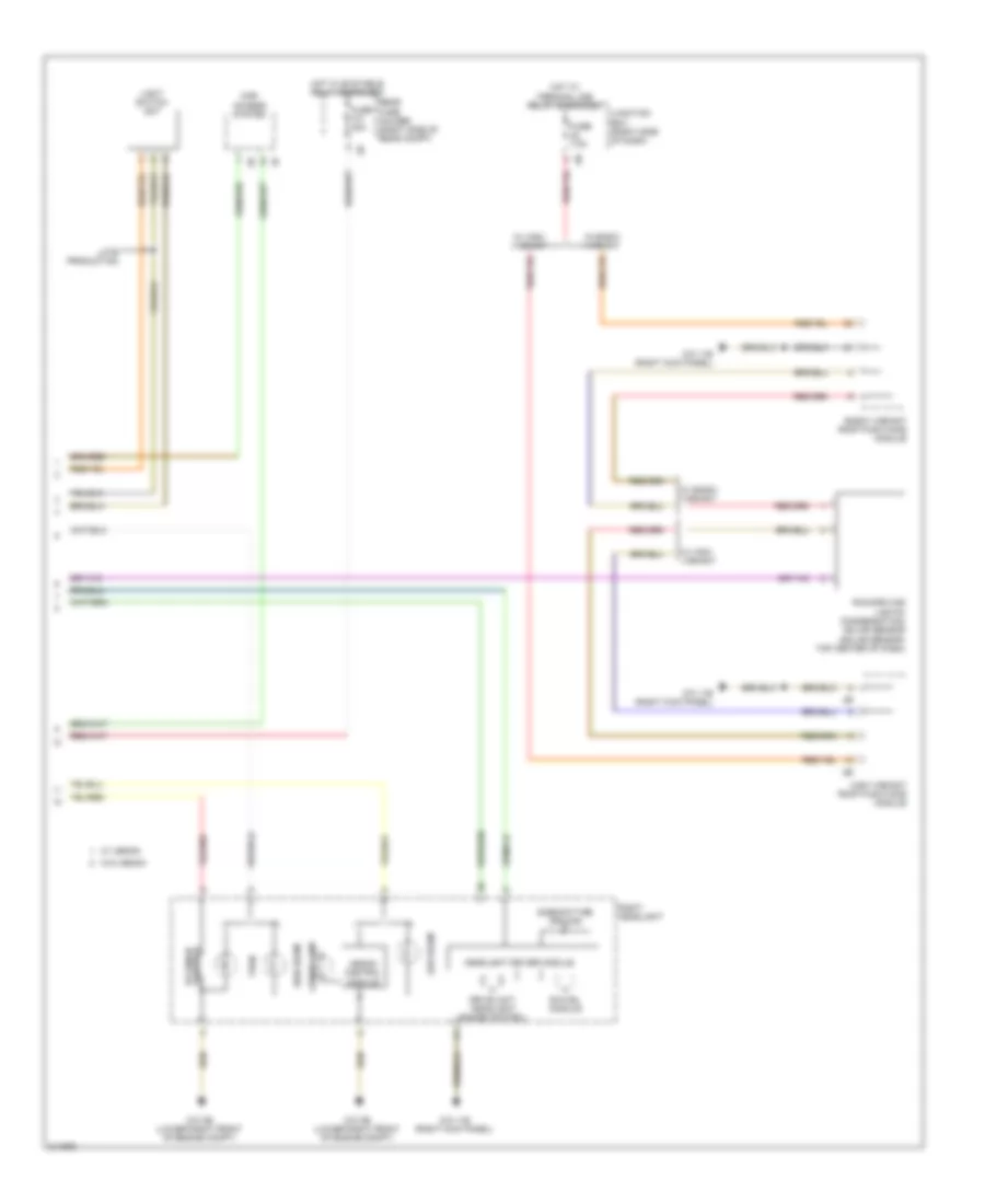
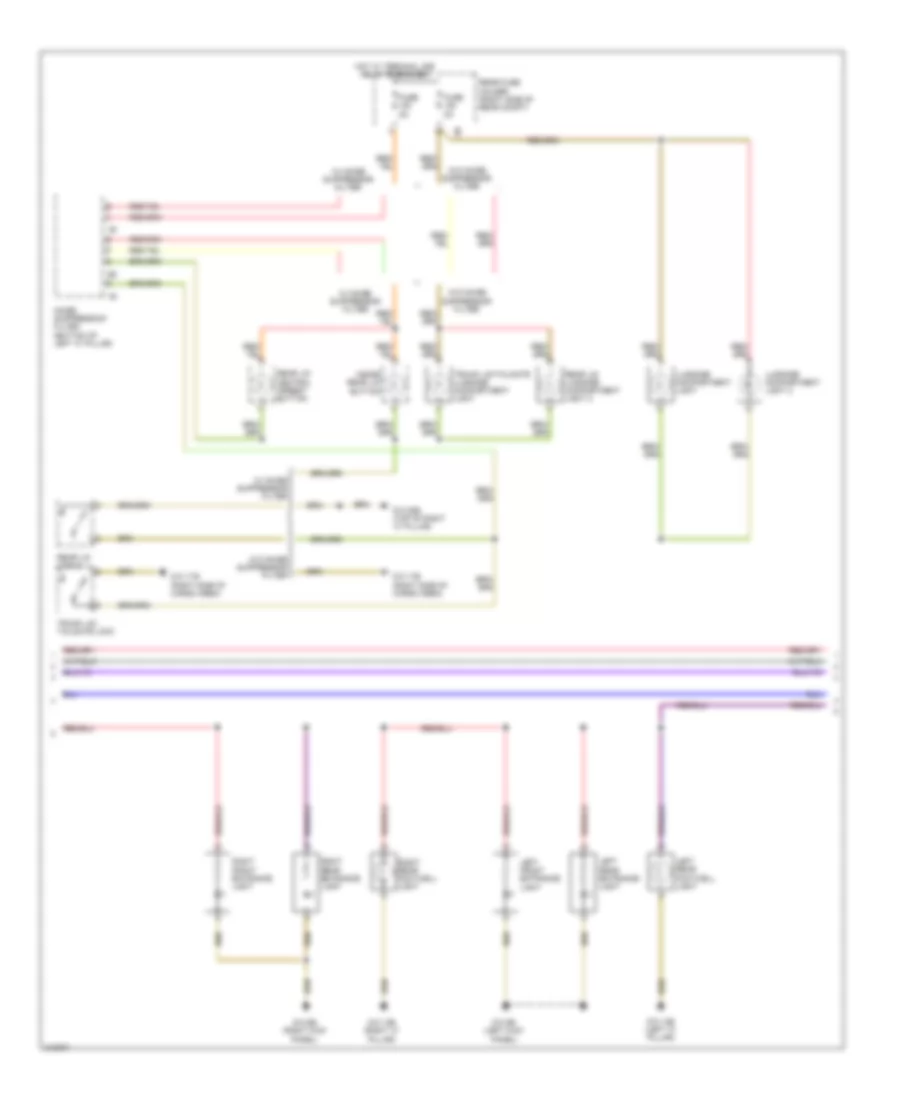
Headlights Wiring Diagram (2 of 2) for BMW 535i GT 2010
List of elements for Headlights Wiring Diagram (2 of 2) for BMW 535i GT 2010:
- Basic variant roof functions module
- Car access system
- Drive unit, headlight range control
- Fuse 40a
- Fuse 7.5a
- Headlight driver module
- High beam
- High variant roof functions module
- Hot w/ bi-stable relay energized
- Hot w/ terminal 30b relay energized
- Junction box (right side of dash)
- Late production
- Light switch unit
- Low beam
- Rain/driving lights/ condensation/ solar sensor (solar sensor: top center of dash)
- Rear fuse holder (right side of rear compt)
- Right headlight
- Shutter bi-xenon
- Side/daytime driving
- Swivel module
- Turn
- W/ basic variant
- W/ high variant
- W/ xenon
- W/o xenon
- Xenon control module
- Xenon lamp
- Z10 11b (right kick panel)
- Z10 3b (lower right front of engine compt)
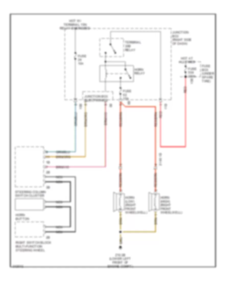
HORN
Horn Wiring Diagram for BMW 535i GT 2010
List of elements for Horn Wiring Diagram for BMW 535i GT 2010:
- 10b
- 11b
- 15b
- Fuse 10a
- Fuse 15a
- Fuse 250a
- Fuse box (under spare tire)
- Horn (high) (right front wheelwell)
- Horn (low) (right front wheelwell)
- Horn button
- Horn relay
- Hot at all times
- Hot w/ terminal 15n relay energized
- Junction box (right side of dash)
- Junction box electronics
- Nca
- Red
- Right switch block multi-function steering wheel
- Steering column switch cluster
- Terminal 30b relay
- X149 1b
- Z10 2b (lower left front of engine compt)
INSTRUMENT CLUSTER
Instrument Cluster Wiring Diagram for BMW 535i GT 2010
List of elements for Instrument Cluster Wiring Diagram for BMW 535i GT 2010:
- 10b
- Anti-theft system
- Computer data lines system
- Coolant level switch (right side of engine compt)
- Fuel level sensor 1
- Fuel level sensor 2
- Fuse 10a
- Fuse 5a
- Head-up display
- Hot at all times
- Hot w/ terminal 30b relay energized
- Instrument cluster control unit
- Junction box (right side of dash)
- Junction box electronics
- Nca
- Outside temperature sensor (under right front of vehicle)
- Red
- Sound systems
- X148 1b
- Z10 6b (right kick panel)
- Z10 9b (left kick panel)
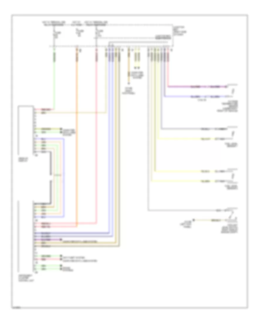
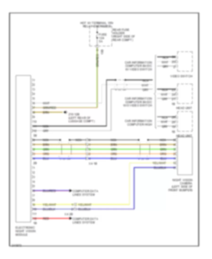
Night Vision Wiring Diagram for BMW 535i GT 2010
List of elements for Night Vision Wiring Diagram for BMW 535i GT 2010:
- 10b
- Car information computer basic w/ video switch
- Car information computer basic w/o video switch
- Car information computer high
- Computer data lines system
- Electronic night vision module
- Fuse 5a
- Head unit
- Hot w/ terminal 15n relay energized
- Nca
- Night vision camera (left side of front bumper)
- Rear fuse holder (right side of rear compt)
- Red
- Video switch
- X4 1b
- X4 2b
- Z10 12b (left rear of luggage compt)
INTERIOR LIGHTS
Courtesy Lamps Wiring Diagram (1 of 3) for BMW 535i GT 2010
List of elements for Courtesy Lamps Wiring Diagram (1 of 3) for BMW 535i GT 2010:
- Electronics junction box
- Fuse 5a
- Fuse 7.5a
- Glove compartment light
- Glove compartment light switch
- High variant roof functions module (w/ high variant) basic variant roof functions module (w/ basic variant)
- Hot w/ terminal 30b relay energized
- Instrument illumination circuit
- Interior light
- Junction box (right side of dash)
- Left front vanity mirror light
- Left front vanity mirror switch
- Left map reading light
- Rear interior light
- Red
- Right front vanity mirror light
- Right front vanity mirror switch
- Right map reading light
- W/ basic variant
- W/ high variant
- Z10 11b (right kick panel)
Courtesy Lamps Wiring Diagram (2 of 3) for BMW 535i GT 2010
List of elements for Courtesy Lamps Wiring Diagram (2 of 3) for BMW 535i GT 2010:
- Fuse 5a
- Hot w/ terminal 30b relay energized
- Inside rear lid button
- Left front entrance light
- Left rear entrance light
- Left rear footwell light
- Luggage compartment light
- Luggage compartment light 2
- Noise suppression filter (bottom of left "c" pillar)
- Rear fuse holder (right side of rear compt)
- Rear lid central arrest button
- Rear lid lock 2
- Rear lid luggage compartment light 2
- Right front entrance light
- Right rear entrance light
- Right rear footwell light
- Trunk lid/ tailgate lock
- Trunk lid/tailgate luggage compartment light
- W/ noise suppressor filter
- W/o noise suppressor filter
- Z10 13b (right "c" pillar)
- Z10 14b (left "c" pillar)
- Z10 17b (right side of cargo area)
- Z10 20b (top of right "c" pillar)
- Z10 5b (left kick panel)
- Z10 6b (right kick panel)
Courtesy Lamps Wiring Diagram (3 of 3) for BMW 535i GT 2010
List of elements for Courtesy Lamps Wiring Diagram (3 of 3) for BMW 535i GT 2010:
- (left kick panel) z10 5b
- Computer data lines system
- Courtesy lighting
- Driver's door apron light
- Driver's door entrance light
- Entrance lt
- Footwell lt
- Footwell module
- Fuse 40a
- Gnd
- Hot w/ bi-stable relay energized
- Interior lt
- Junction box (right side of dash)
- Junction box electronics
- K-can bus sig
- Left front footwell light
- Passenger's door entrance light
- Passenger's door far-field light
- Pwr sply
- Rear driver's side courtesy lighting
- Rear driver's side entry light
- Rear passenger's side courtesy lighting
- Rear passenger's side entry light
- Right front footwell light
- Signal, switch
- Switch signal
- X28 1b
- X5 1b
- X8 1b
- X9 1b
- Z10 5b (left kick panel)
- Z10 6b (right kick panel)
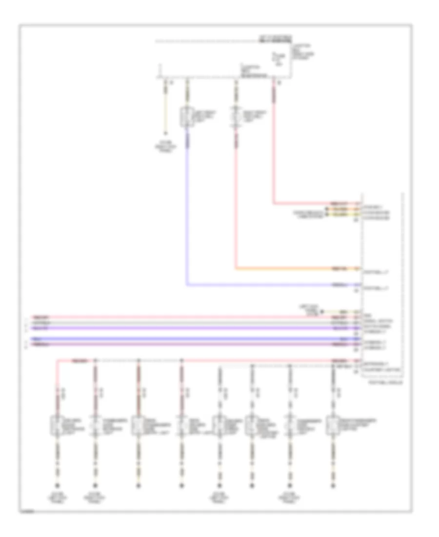
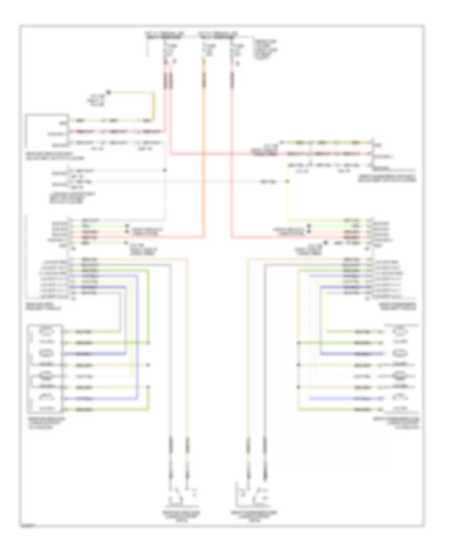
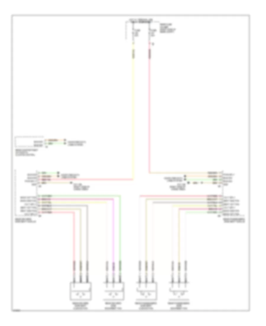
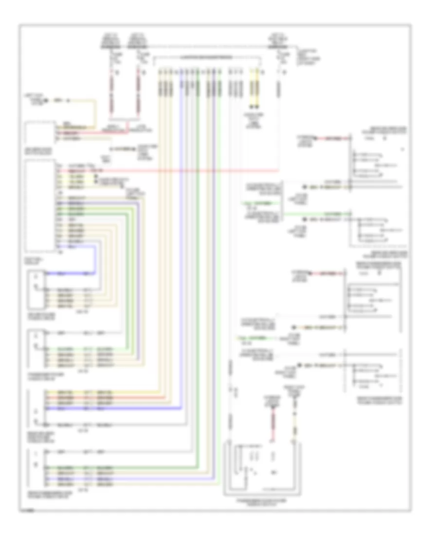
Instrument Illumination Wiring Diagram (1 of 2) for BMW 535i GT 2010
List of elements for Instrument Illumination Wiring Diagram (1 of 2) for BMW 535i GT 2010:
- Ambient light
- Ambient lt
- Basic variant roof functions module
- Center console control panel
- Center front ventilation grille
- Central locking button operating unit hazard warning switch
- Computer data lines system
- Driver's side dashboard decor strip lighting
- Dvd changer (left side of rear compt)
- Footwell module
- Fuse 10a
- Fuse 5a
- Gnd
- Ground
- Heating/air conditioning system
- High variant roof functions module
- Hot w/ bi-stable relay energized
- Interior rear lid button
- Junction box (right side of dash)
- Junction box electronics
- K-can bus sig
- Late production
- Left front ventilation grille
- Left side center console panel lighting
- Light switch unit
- Lin bus sig
- Parking brake button
- Passenger's door pocket lighting
- Passenger's door power window switch
- Passenger's door trim panel lighting
- Passenger's side dashboard decor strip lighting
- Passenger's side dashboard decor strip lighting 2
- Pwr sply
- Rear interior light
- Rear seat entertainment
- Right front ventilation grille
- Right side center console panel lighting
- W/ basic variant
- W/ high variant
- X5 1b
- X501 1b
- Z10 11b (right kick panel)
- Z10 12b (left rear of luggage compt)
- Z10 17b (right side of cargo area)
- Z10 5b (left kick panel)
- Z10 6b (right kick panel)
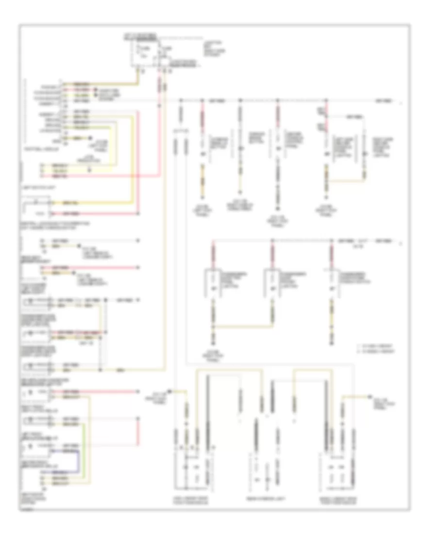
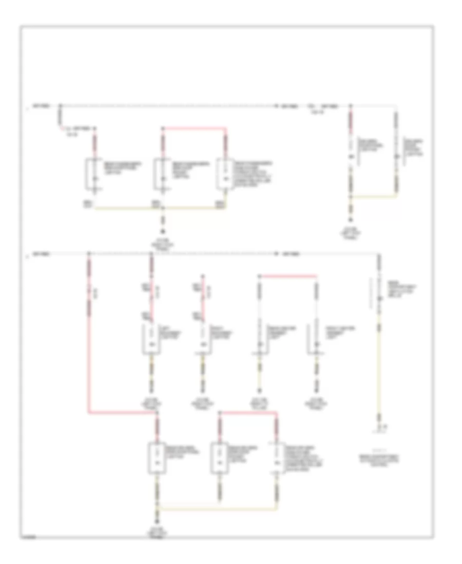
Instrument Illumination Wiring Diagram (2 of 2) for BMW 535i GT 2010
List of elements for Instrument Illumination Wiring Diagram (2 of 2) for BMW 535i GT 2010:
- Driver's door panel lighting
- Driver's door pocket lighting
- Front center armrest light
- Left backrest lighting
- Rear center armrest light
- Rear compartment automatic climate control
- Rear compartment ventilation grille
- Rear driver's side door panel lighting
- Rear driver's side door pocket lighting
- Rear driver's side power window switch (w/o electrically operated roller sun blinds)
- Rear passenger's side door panel lighting
- Rear passenger's side door pocket lighting
- Rear passenger's side power window switch (w/o electrically operated roller sun blinds)
- Right backrest lighting
- X12 1b
- X14 1b
- X28 1b
- X8 1b
- X9 1b
- Z10 13b (right "c" pillar)
- Z10 5b (left kick panel)
- Z10 6b (right kick panel)
MEMORY SYSTEMS
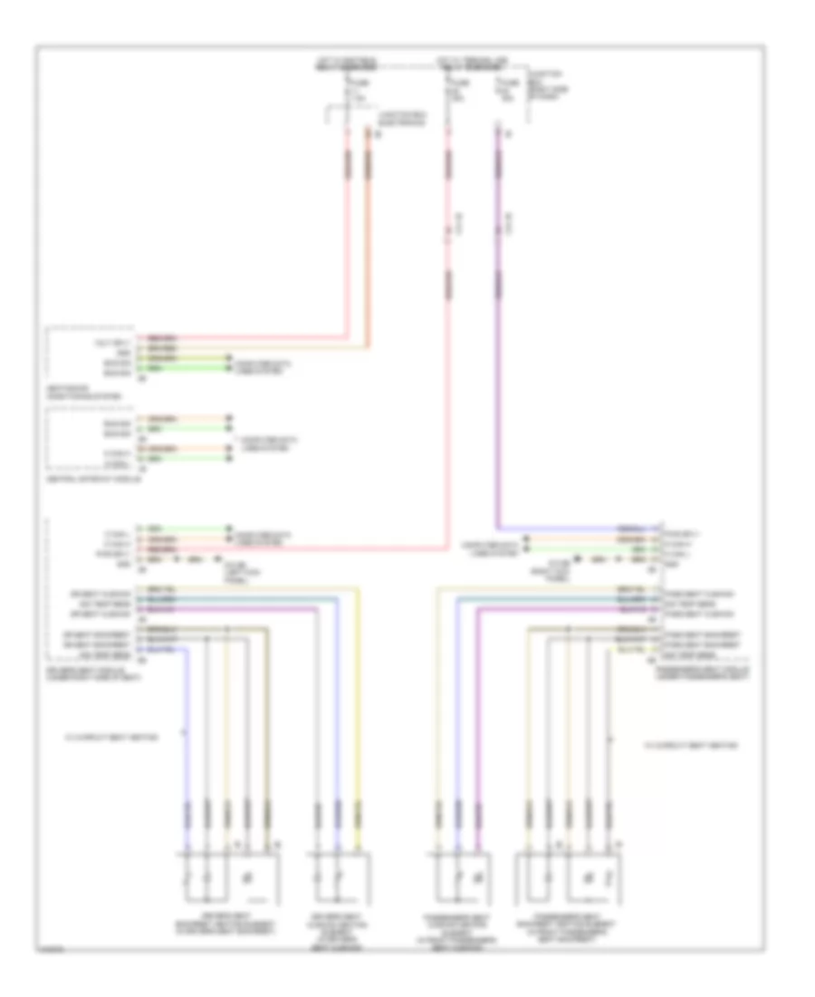
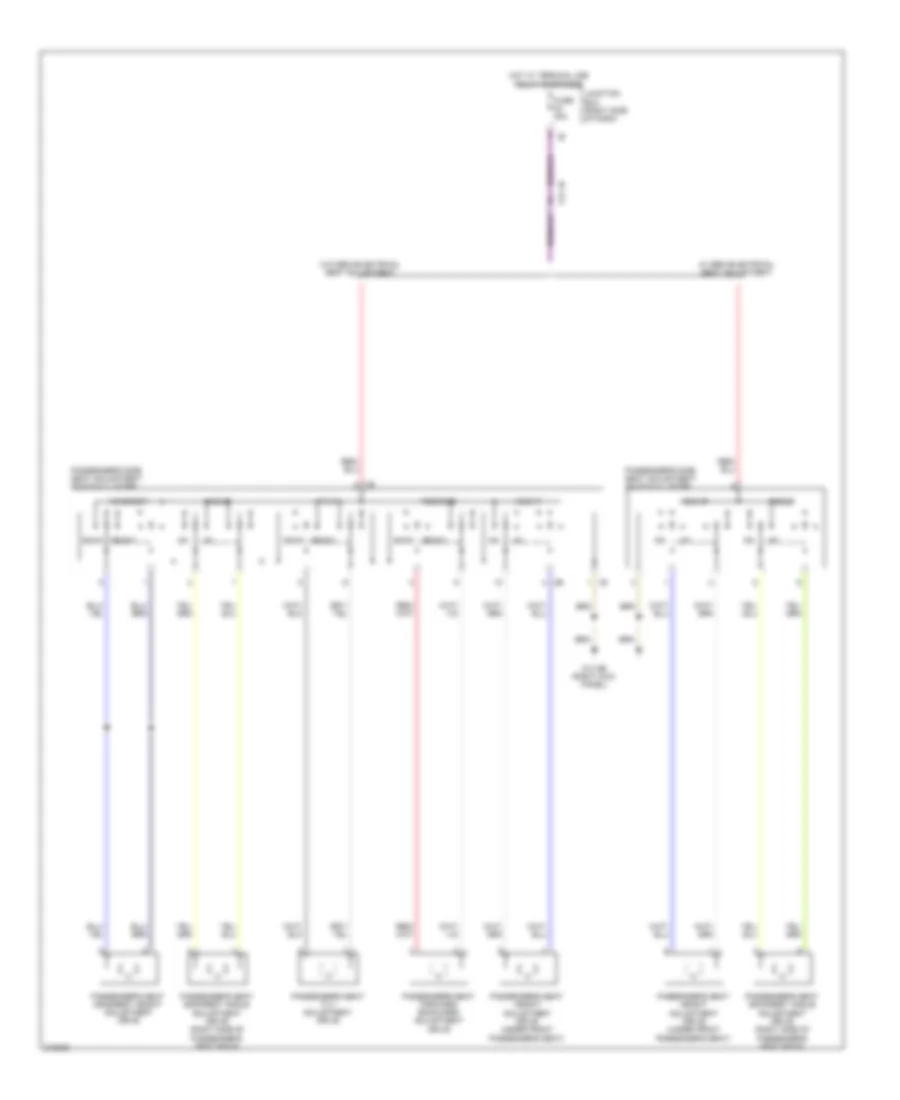
Driver"s Memory Seat Wiring Diagram (1 of 2) for BMW 535i GT 2010
List of elements for Driver"s Memory Seat Wiring Diagram (1 of 2) for BMW 535i GT 2010:
- Actuator motor
- Angle
- Bus sig
- Computer data lines system
- Depth
- Driver's door seat switch cluster
- Driver's seat angle adjustment drive unit (under driver's seat)
- Driver's seat depth adjustment motor (w/ multi-function seat or sport seat) (under driver's seat)
- Driver's seat forward/ backward adjustment drive unit (under driver seat)
- Driver's seat height adjustment drive unit (under driver's seat)
- Driver's seat module (under right side of seat)
- Footwell module
- For/back
- Fuse 10a
- Fuse 30a
- Fuse 7.5a
- Gnd
- Gnd hall sens
- Hall sensor
- Height
- Hot w/ terminal 30b relay energized
- Junction box (right side of dash)
- Power distribution system
- Pwr sply
- Red
- Seat backrest
- Seat cushion
- Seats system
- Sig temp sens
- X14 1b
- Z10 5b (left kick panel)
Driver"s Memory Seat Wiring Diagram (2 of 2) for BMW 535i GT 2010
List of elements for Driver"s Memory Seat Wiring Diagram (2 of 2) for BMW 535i GT 2010:
- (w/ multi-function seat) driver's side seat adjustment switch cluster
- (w/o multi-function seat) driver's side seat adjustment switch cluster
- Actuator motor
- Back act fan
- Back angle
- Back gnd fan
- Back head
- Back width
- Bus sig
- Cam operated
- Driver's seat backrest angle adjustment drive
- Driver's seat backrest head adjustment drive (w/ multi-function seat) (left side of seat back)
- Driver's seat backrest width adjustment drive (w/ multi-function seat or sport seat) (bottom right of seat back)
- Driver's seat headrest height adjustment drive
- Driver's seat module (under right side of seat)
- Gnd
- Hall sens
- Hall sensor
- Headrest
- Lum sup active
- Lum sup gnd
- Lum sup vlv 1
- Lum sup vlv 2
- Lum sup vlv 3
- Lum sup vlv 4
- Lum sup volt
- Pressure gnd
- Pwr sply
- Red
- Seat act fan
- Seat gnd fan
- Seats system
- Vlv block gnd
- Volt sply
- Z10 5b (left kick panel)
Left Memory Rear Seat Wiring Diagram (1 of 2) for BMW 535i GT 2010
List of elements for Left Memory Rear Seat Wiring Diagram (1 of 2) for BMW 535i GT 2010:
- Actuator motor
- Bus sig
- Computer data lines system
- Footwell module
- For/back
- Fuse 30a
- Fuse 5a
- Gnd
- Gnd hall sens
- Hall sens
- Hall sensor
- Headrest
- Hot w/ terminal 30b relay energized
- Power distribution system
- Pwr sply
- Rear driver's side door seat switch cluster
- Rear driver's side headrest height adjustment drive
- Rear driver's side seat forward/ backward adjustment drive
- Rear driver's side seat module
- Rear fuse holder (right side of rear compt)
- Seat backrest
- Seat cushion
- Seats system
- Sig temp sens
- X8 1b
- Z10 13b (right side of cargo area)
- Z10 5b (left kick panel)
Left Memory Rear Seat Wiring Diagram (2 of 2) for BMW 535i GT 2010
List of elements for Left Memory Rear Seat Wiring Diagram (2 of 2) for BMW 535i GT 2010:
- 2nd stage
- Actuator motor
- Back act fan
- Back angle
- Back gnd fan
- Back width
- Bus sig
- Cam operated
- Cam sw sig
- Fuse 5a
- Gnd
- Hall sens
- Hall sensor
- Hot w/ terminal 30b relay energized
- Luggage compartment seat adjustment switch cluster
- Lum sup active
- Lum sup gnd
- Lum sup vlv 1
- Lum sup vlv 2
- Lum sup vlv 3
- Lum sup vlv 4
- Lum sup volt
- Nca
- Pressure gnd
- Pwr sply
- Rear driver's side backrest angle adjustment drive
- Rear driver's side backrest head adjustment drive
- Rear driver's side seat adjustment switch cluster
- Rear driver's side seat module
- Rear fuse holder (right side of rear compt)
- Red
- S91 1b
- Seat act fan
- Seat gnd fan
- Seats system
- Vlv block gnd
- Volt sply
- X257 1b
- X81 1b
- Z10 13b (right "c" pillar)
- Z10 14b (left side of cargo area)
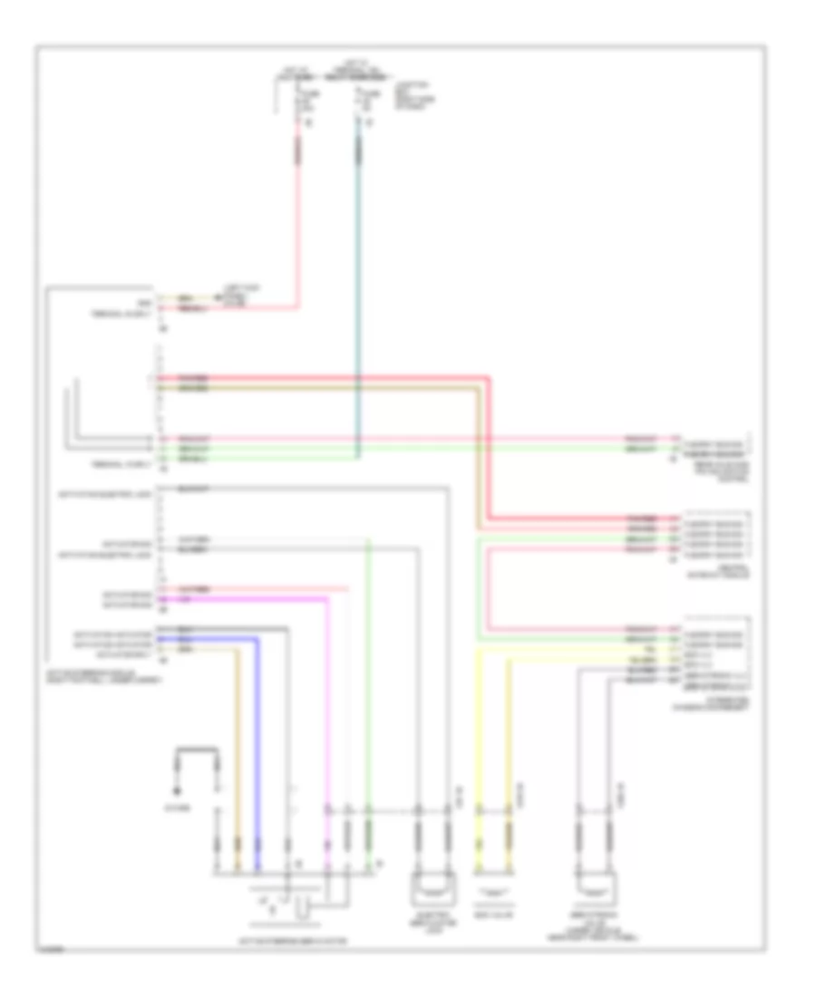
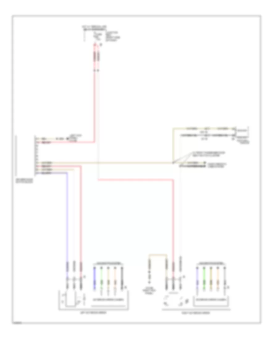
Memory Mirrors Wiring Diagram, with LIN bus Function for BMW 535i GT 2010
List of elements for Memory Mirrors Wiring Diagram, with LIN bus Function for BMW 535i GT 2010:
- (left kick panel) z10 5b
- Bus sig
- Computer data lines system
- Driver's door switch block
- Exterior mirror camera
- Footwell module
- Fuse 7.5a
- Hot w/ terminal 30b relay energized
- Junction box (right side of dash)
- Left exterior mirror
- Navigation system
- Nca
- Right exterior mirror
- W/ front passenger door seat switch cluster
- X28 1b
- X5 1b
- Z10 6b (right kick panel)
Memory Mirrors Wiring Diagram, without LIN bus Function for BMW 535i GT 2010
List of elements for Memory Mirrors Wiring Diagram, without LIN bus Function for BMW 535i GT 2010:
- Computer data lines system
- Driver's door switch block
- Early production
- Fuse 7.5a
- Hot w/ terminal 30b relay energized
- Junction box (right side of dash)
- Junction box electronics
- Late production
- Left exterior mirror
- Right exterior mirror
- X28 1b
- X5 1b
- Z10 5b (left kick panel)
- Z10 6b (right kick panel)
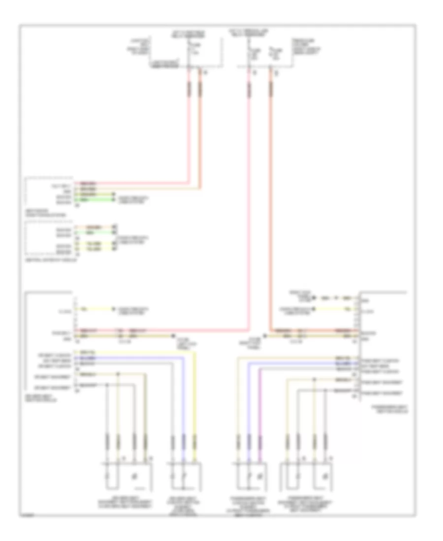
Passenger"s Memory Seat Wiring Diagram (1 of 2) for BMW 535i GT 2010
List of elements for Passenger"s Memory Seat Wiring Diagram (1 of 2) for BMW 535i GT 2010:
- Actuator motor
- Bus sig
- Computer data lines system
- Depth
- Footwell module
- For/back
- Fuse 10a
- Fuse 30a
- Fuse 7.5a
- Gnd
- Gnd hall sens
- Hall sensor
- Height
- Hot w/ terminal 30b relay energized
- Junction box (right side of dash)
- Passenger's door seat switch cluster
- Passenger's seat depth adjustment drive (w/ multi-function seat or sport seat) (under front passenger's seat)
- Passenger's seat forward/ backward adjustment drive
- Passenger's seat height adjustment drive unit (under front passenger's seat)
- Passenger's seat module (under passenger's seat)
- Passenger's seat tilt adjustment drive
- Power distribution system
- Pwr sply
- Red
- Seat backrest
- Seat cushion
- Seats system
- Sig temp sens
- Tilt
- X12 1b
- Z10 6b (right kick panel)
Passenger"s Memory Seat Wiring Diagram (2 of 2) for BMW 535i GT 2010
List of elements for Passenger"s Memory Seat Wiring Diagram (2 of 2) for BMW 535i GT 2010:
- (w/ multi-function seat) passenger's side seat adjustment switch cluster
- (w/o multi-function seat) passenger's side seat adjustment switch cluster
- Actuator motor
- Back act fan
- Back angle
- Back gnd fan
- Back head
- Back width
- Bus sig
- Cam operated
- Cam sw sig
- Gnd
- Hall sens
- Hall sensor
- Headrest
- Lum sup active
- Lum sup gnd
- Lum sup vlv 1
- Lum sup vlv 2
- Lum sup vlv 3
- Lum sup vlv 4
- Lum sup volt
- Passenger's seat backrest angle adjustment drive (right side of passenger's seat back)
- Passenger's seat backrest head adjustment drive (w/ multi-function seat) (right side of seat back)
- Passenger's seat backrest width adjustment drive (w/ multi-function seat or sport seat) (bottom left of seat back)
- Passenger's seat headrest height adjustment drive
- Passenger's seat module (under passenger's seat)
- Pressure gnd
- Pwr sply
- Red
- Seat act fan
- Seat gnd fan
- Seat sw gnd
- Seat sw sply
- Seats system
- Sw sig
- Vlv block gnd
- Volt sply
- Z10 6b (right kick panel)
Right Memory Rear Seat Wiring Diagram (1 of 2) for BMW 535i GT 2010
List of elements for Right Memory Rear Seat Wiring Diagram (1 of 2) for BMW 535i GT 2010:
- Actuator motor
- Angle
- Bus sig
- Computer data lines system
- Footwell module
- For/back
- Fuse 30a
- Fuse 5a
- Gnd
- Gnd hall sens
- Hall sens
- Hall sensor
- Headrest
- Hot w/ terminal 30b relay energized
- Power distribution system
- Pwr sply
- Rear fuse holder (right side of rear compt)
- Rear passenger's side door seat switch cluster
- Rear passenger's side headrest height adjustment drive
- Rear passenger's side seat forward/ backward adjustment drive
- Rear passenger's side seat module
- Seat backrest
- Seat cushion
- Seats system
- Sig temp sens
- X9 1b
- Z10 13b (right side of cargo area)
- Z10 6b (right kick panel)
Right Memory Rear Seat Wiring Diagram (2 of 2) for BMW 535i GT 2010
List of elements for Right Memory Rear Seat Wiring Diagram (2 of 2) for BMW 535i GT 2010:
- (right side of cargo area)
- 2nd stage
- Actuator motor
- Back act fan
- Back angle
- Back gnd fan
- Back width
- Bus sig
- Cam operated
- Cam sw sig
- Fuse 5a
- Gnd
- Hall sens
- Hall sensor
- Hot w/ terminal 30b relay energized
- Luggage compartment seat adjustment switch cluster
- Lum sup active
- Lum sup gnd
- Lum sup vlv 1
- Lum sup vlv 2
- Lum sup vlv 3
- Lum sup vlv 4
- Lum sup volt
- Nca
- Power distribution system
- Pressure gnd
- Pwr sply
- Rear fuse holder (right side of rear compt)
- Rear passenger's side backrest angle adjustment drive
- Rear passenger's side backrest head adjustment drive
- Rear passenger's side seat adjustment switch cluster
- Rear passenger's side seat module
- Red
- S92 1b
- Seat act fan
- Seat gnd fan
- Seats system
- Shield
- Vlv block gnd
- Volt sply
- X10 1b
- X28 1b
- Z10 13b
- Z10 14b (left side of cargo area)
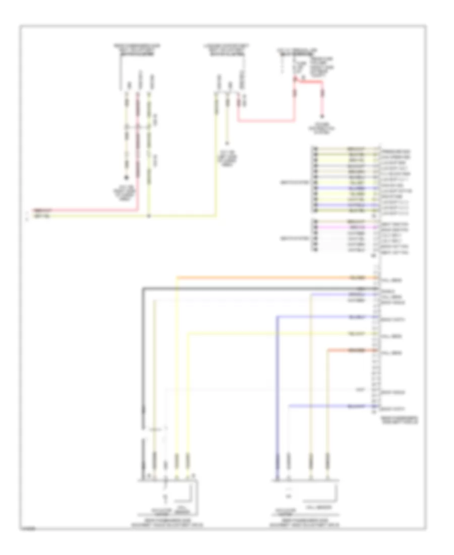
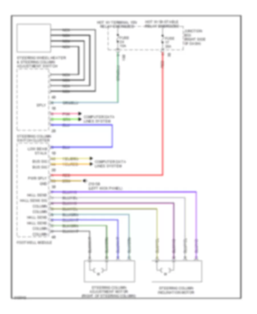
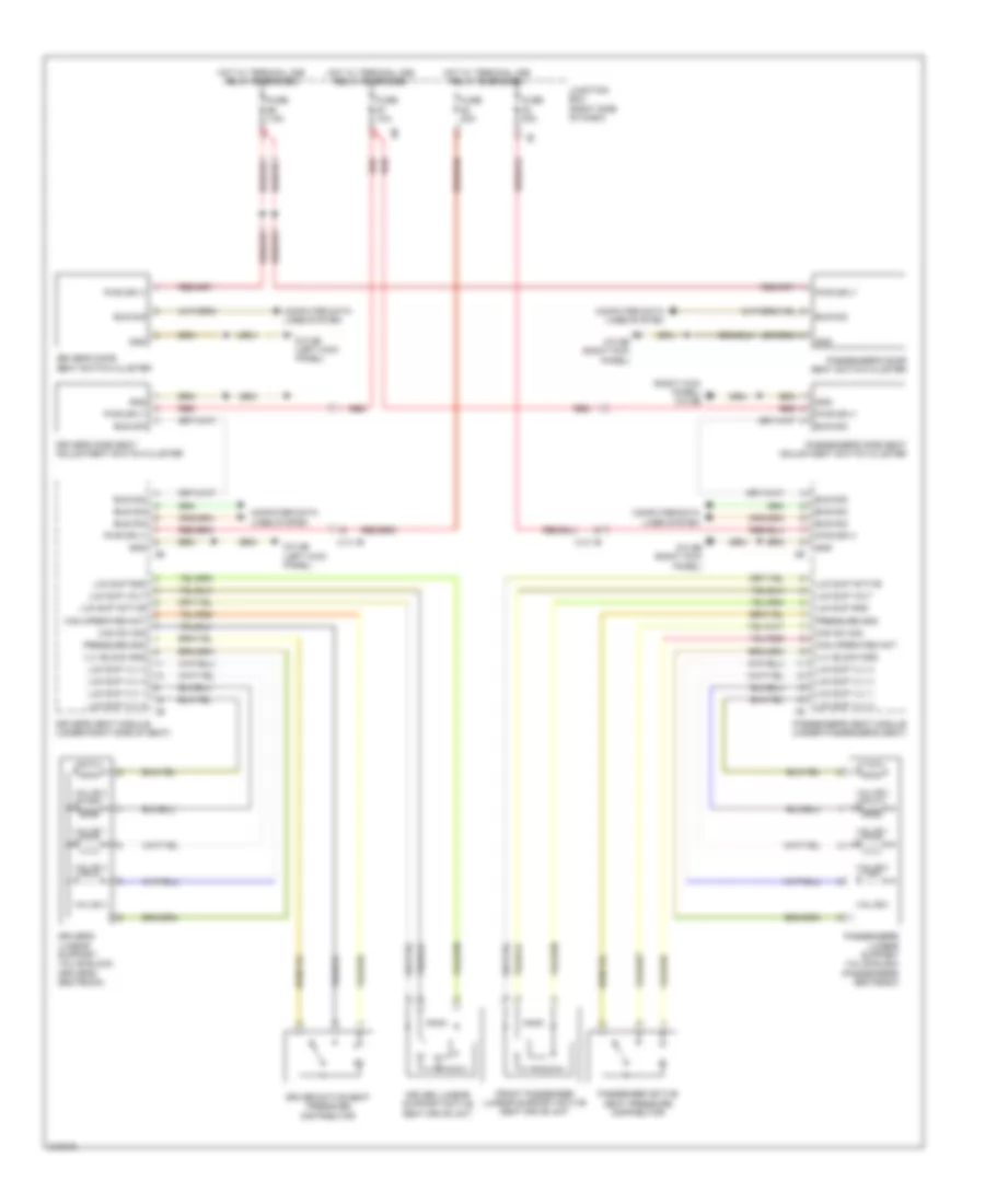
Steering Column Memory Wiring Diagram for BMW 535i GT 2010
List of elements for Steering Column Memory Wiring Diagram for BMW 535i GT 2010:
- 10b
- Bus sig
- Column
- Computer data lines system
- Footwell module
- Fuse 10a
- Fuse 30a
- Gnd
- Hall sens
- Hall sens sig
- Hot w/ bi-stable relay energized
- Hot w/ terminal 15n relay energized
- Junction box (right side of dash)
- Low beam stalk 1b
- Nca
- Pnk
- Pwr sply
- Red
- Sply
- Steering column adjustment motor (right of steering column)
- Steering column inclination motor
- Steering column switch cluster
- Steering wheel heater & steering column adjustment switch
- Z10 5b (left kick panel)
NAVIGATION
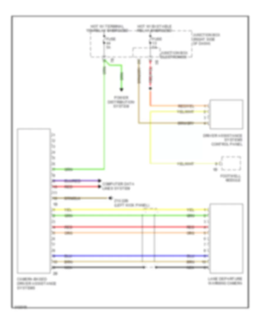
Lane Departure Warning Wiring Diagram, with Camera for BMW 535i GT 2010
List of elements for Lane Departure Warning Wiring Diagram, with Camera for BMW 535i GT 2010:
- Camera-based driver assistance systems
- Computer data lines system
- Driver assistance systems control panel
- Footwell module
- Fuse 5a
- Hot w/ bi-stable relay energized
- Hot w/ terminal 15n relay energized
- Junction box (right side of dash)
- Junction box electronics
- Lane departure warning camera
- Nca
- Power distribution system
- Red
- Z10 22b (left kick panel)
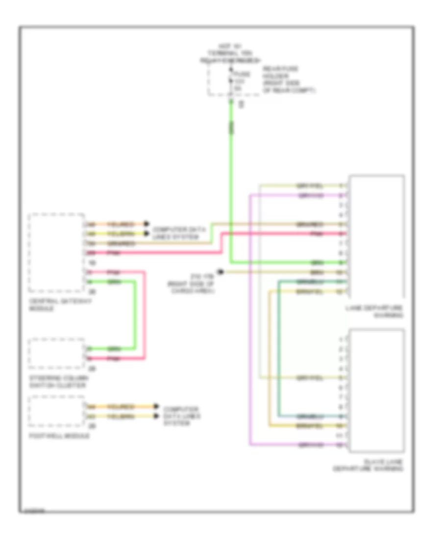
Lane Departure Warning Wiring Diagram, without Camera for BMW 535i GT 2010
List of elements for Lane Departure Warning Wiring Diagram, without Camera for BMW 535i GT 2010:
- Central gateway module
- Computer data lines system
- Footwell module
- Fuse 5a
- Hot w/ terminal 15n relay energized
- Lane departure warning
- Pnk
- Rear fuse holder (right side of rear compt)
- Slave lane departure warning
- Steering column switch cluster
- Z10 17b (right side of cargo area)
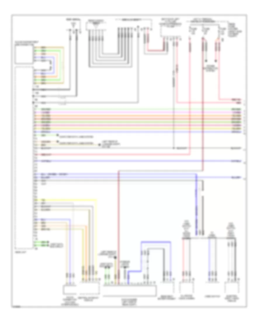
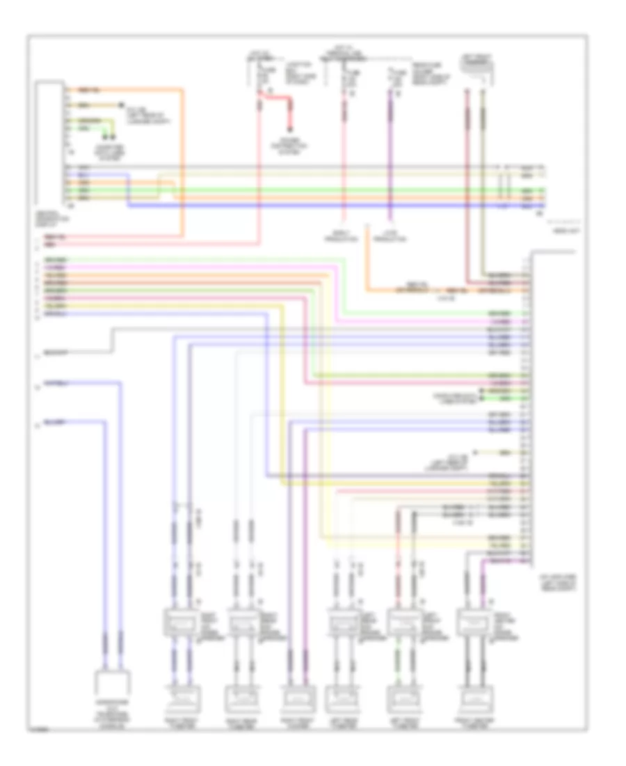
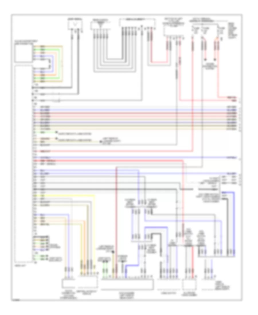
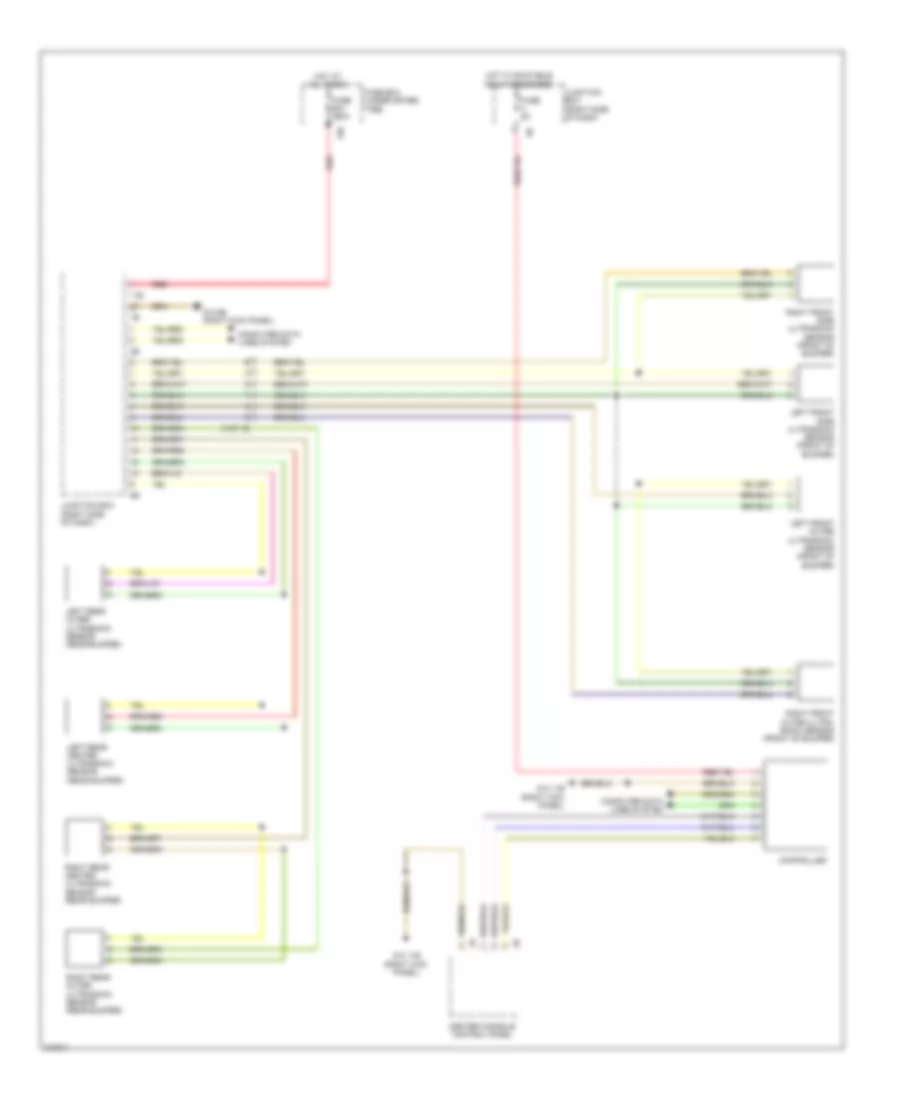
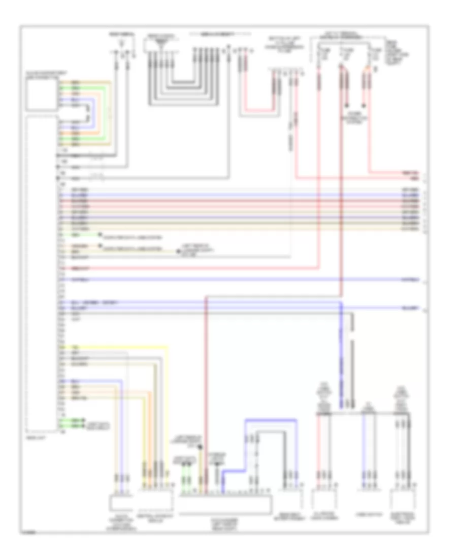
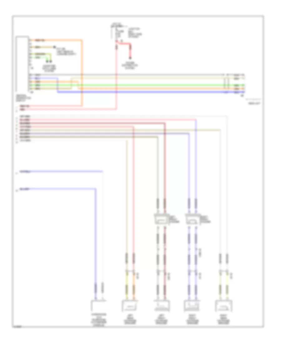
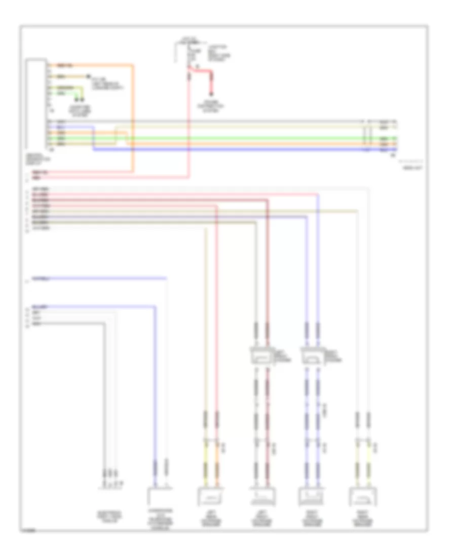
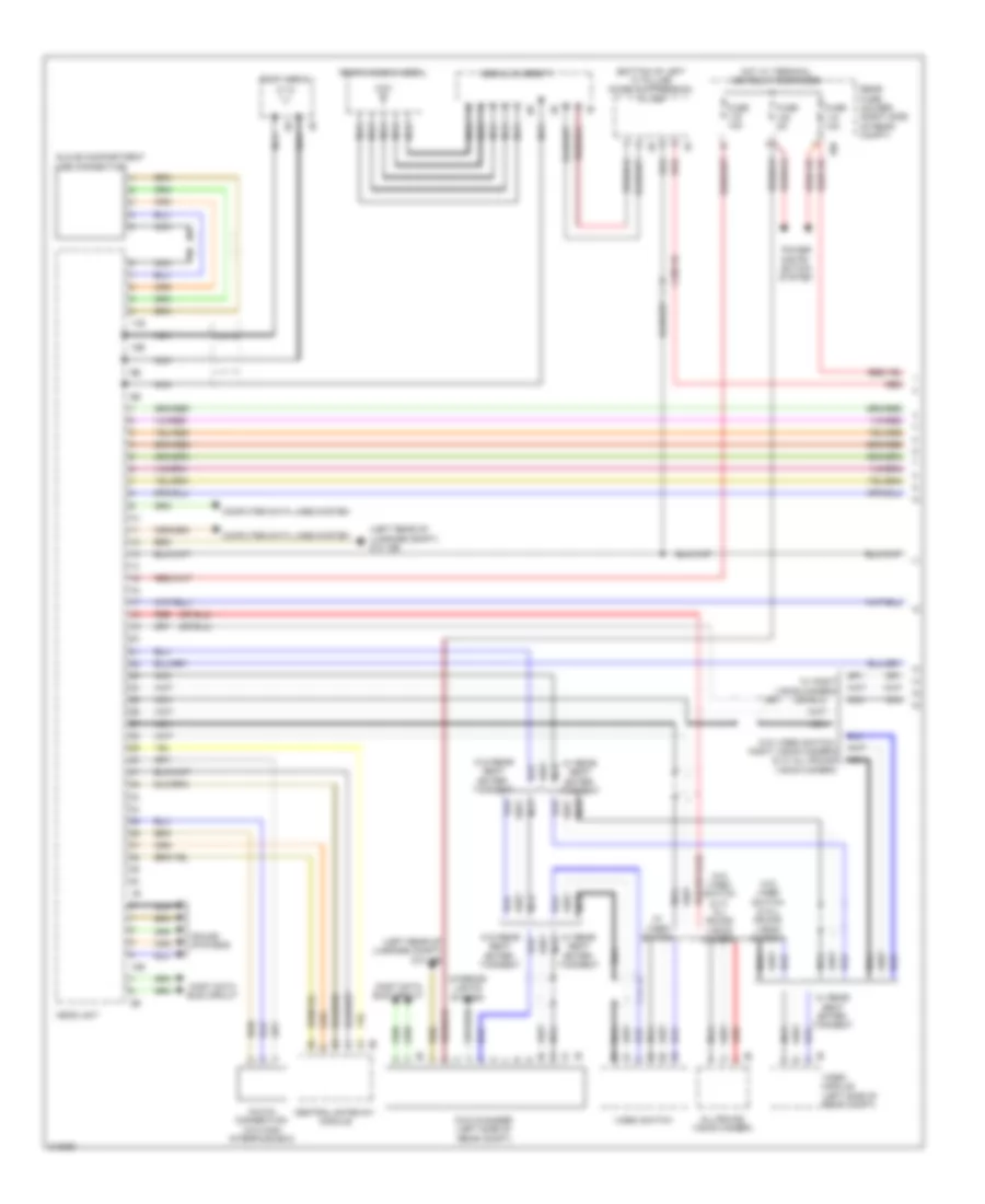
Navigation Wiring Diagram, Basic with Hifi Radio (1 of 2) for BMW 535i GT 2010
List of elements for Navigation Wiring Diagram, Basic with Hifi Radio (1 of 2) for BMW 535i GT 2010:
- (bottom of left "c" pillar) noise suppression filter
- (left rear of luggage compt) z10 12b
- (or red)
- 10b
- 11b
- 15b
- Aerial diversity
- All-round vision camera
- Aux-in connection (w/o high interface box)
- Central gateway module
- Computer data lines system
- Dvd changer (left side of rear compt)
- Electric night vision module
- Fuse 10a
- Fuse 15a
- Fuse 5a
- Glove compartment usb connection
- Head unit
- Hot w/ terminal 30b relay energized
- Interior lights system
- Most data bus circuit
- Nca
- Power distribution system
- Rear fuse holder (right side of rear compt)
- Rear seat entertainment
- Rear window aerial
- Red
- Roof aerial
- Video switch
- W/ video switch
- W/o video switch & w/ all round vision camera
- W/o video switch & w/ night vision camera
- X188 1b
Navigation Wiring Diagram, Basic with Hifi Radio (2 of 2) for BMW 535i GT 2010
List of elements for Navigation Wiring Diagram, Basic with Hifi Radio (2 of 2) for BMW 535i GT 2010:
- Central information display
- Computer data lines system
- Early production
- Front center mid- range speaker
- Front center tweeter
- Fuse 30a
- Fuse 5a
- Head unit
- Hifi amplifier (left side of rear compt)
- Hot at all times
- Hot w/ terminal 30b relay energized
- Junction box (right side of dash)
- Late production
- Left front mid- range speaker
- Left front tweeter
- Left front woofer
- Left rear mid- range speaker
- Left rear tweeter
- Microphone (w/o telephone) (in overhead console)
- Nca
- Power distribution system
- Rear fuse holder (right side of rear compt)
- Red
- Right front mid- range speaker
- Right front tweeter
- Right front woofer
- Right rear mid- range speaker
- Right rear tweeter
- X188 1b
- X19 1b
- X28 1b
- X5 1b
- X8 1b
- X9 1b
- Z10 12b (left rear of luggage compt)
Navigation Wiring Diagram, Basic without Hifi Radio (1 of 2) for BMW 535i GT 2010
List of elements for Navigation Wiring Diagram, Basic without Hifi Radio (1 of 2) for BMW 535i GT 2010:
- (bottom of left "c" pillar) noise suppression filter
- (left rear of luggage compt) z10 12b
- (or red)
- 10b
- 11b
- 15b
- Aerial diversity
- All-round vision camera
- Aux-in connection (w/o high interface box)
- Central gateway module
- Computer data lines system
- Dvd changer (left side of rear compt)
- Electronic night vision module
- Fuse 10a
- Fuse 15a
- Fuse 5a
- Glove compartment usb connection
- Head unit
- Hot w/ terminal 30b relay energized
- Interior lights system
- Most data bus circuit
- Nca
- Power distribution system
- Rear fuse holder (right side of rear compt)
- Rear seat entertainment
- Rear window aerial
- Red
- Roof aerial
- Video switch
- W/ video switch
- W/o video switch & w/ all round vision camera
- W/o video switch & w/ night vision camera
- X188 1b
Navigation Wiring Diagram, Basic without Hifi Radio (2 of 2) for BMW 535i GT 2010
List of elements for Navigation Wiring Diagram, Basic without Hifi Radio (2 of 2) for BMW 535i GT 2010:
- Central information display
- Computer data lines system
- Fuse 5a
- Head unit
- Hot at all times
- Junction box (right side of dash)
- Left front mid range speaker
- Left front woofer
- Left rear mid range speaker
- Microphone (w/o telephone) (in overhead console)
- Nca
- Power distribution system
- Red
- Right front mid range speaker
- Right front woofer
- Right rear mid range speaker
- X188 1b
- X28 1b
- X5 1b
- X8 1b
- X9 1b
- Z10 12b (left rear of luggage compt)
Navigation Wiring Diagram, High with Hifi Radio (1 of 2) for BMW 535i GT 2010
List of elements for Navigation Wiring Diagram, High with Hifi Radio (1 of 2) for BMW 535i GT 2010:
- (bottom of left "c" pillar) noise suppression filter
- (left rear of luggage compt) z10 12b
- 10b
- 11b
- 15b
- Aerial diversity
- All-round vision camera
- Aux-in connection (w/o high interface box)
- Central gateway module
- Computer data lines system
- Dvd changer (left side of rear compt)
- Fuse 10a
- Fuse 15a
- Fuse 5a
- Glove compartment usb connection
- Head unit
- Hot w/ terminal 30b relay energized
- Interior lights system
- Most data bus circuit
- Nca
- Power distri- bution system
- Rear fuse holder (right side of rear compt)
- Rear window aerial
- Red
- Roof aerial
- Sound systems
- Video module (left side of rear compt)
- Video switch
- W/ night vision camera
- W/ rear seat enter- tainment
- W/ video switch
- W/o rear seat enter- tainment
- W/o video switch & all round vision camera
- W/o video switch & w/ all round vision camera
- W/o video switch, night vision camera & w/ all round vision camera
- X188 1b
Navigation Wiring Diagram, High with Hifi Radio (2 of 2) for BMW 535i GT 2010
List of elements for Navigation Wiring Diagram, High with Hifi Radio (2 of 2) for BMW 535i GT 2010:
- (in overhead console)
- Central information display
- Computer data lines system
- Early production
- Electronic night vision module
- Front center mid- range speaker
- Front center tweeter
- Fuse 30a
- Fuse 5a
- Head unit
- Hifi amplifier (left side of rear compt)
- Hot at all times
- Hot w/ terminal 30b relay energized
- Junction box (right side of dash)
- Late production
- Left front mid- range speaker
- Left front tweeter
- Left front woofer
- Left rear mid- range speaker
- Left rear tweeter
- Microphone (w/o telephone)
- Nca
- Power distribution system
- Rear fuse holder (right side of rear compt)
- Red
- Right front mid- range speaker
- Right front tweeter
- Right front woofer
- Right rear mid- range speaker
- Right rear tweeter
- X188 1b
- X19 1b
- X28 1b
- X5 1b
- X8 1b
- X9 1b
- Z10 12b (left rear of luggage compt)
Navigation Wiring Diagram, High without Hifi Radio (1 of 2) for BMW 535i GT 2010
List of elements for Navigation Wiring Diagram, High without Hifi Radio (1 of 2) for BMW 535i GT 2010:
- (bottom of left "c" pillar) noise suppression filter
- (left rear of luggage compt) z10 12b
- 10b
- 11b
- 15b
- Aerial diversity
- All-round vision camera
- Aux-in connection (w/o high interface box)
- Central gateway module
- Computer data lines system
- Dvd changer (left side of rear compt)
- Fuse 10a
- Fuse 15a
- Fuse 5a
- Glove compartment usb connection
- Head unit
- Hot w/ terminal 30b relay energized
- Interior lights system
- Most data bus circuit
- Nca
- Power distribution system
- Rear fuse holder (right side of rear compt)
- Rear window aerial
- Red
- Roof aerial
- Sound systems
- Video module (left side of rear compt)
- Video switch
- W/ night vision camera
- W/ rear seat enter- tainment
- W/ video switch
- W/o rear seat enter- tainment
- W/o video switch & all round vision camera
- W/o video switch & w/ all round vision camera
- W/o video switch, night vision camera & w/ all round vision camera
- X188 1b
Navigation Wiring Diagram, High without Hifi Radio (2 of 2) for BMW 535i GT 2010
List of elements for Navigation Wiring Diagram, High without Hifi Radio (2 of 2) for BMW 535i GT 2010:
- Central information display
- Computer data lines system
- Electronic night vision module
- Fuse 5a
- Head unit
- Hot at all times
- Junction box (right side of dash)
- Left front mid range speaker
- Left front woofer
- Left rear mid range speaker
- Microphone (w/o telephone) (in overhead console)
- Nca
- Power distribution system
- Red
- Right front mid range speaker
- Right front woofer
- Right rear mid range speaker
- X188 1b
- X28 1b
- X5 1b
- X8 1b
- X9 1b
- Z10 12b (left rear of luggage compt)
Parking Assistant Wiring Diagram for BMW 535i GT 2010
List of elements for Parking Assistant Wiring Diagram for BMW 535i GT 2010:
- 11b
- 15b
- Center console control panel
- Computer data lines system
- Controller
- Fuse 250a
- Fuse 5a
- Fuse box (under spare tire)
- Hot at all times
- Hot w/ bi-stable relay energized
- Junction box (right side of dash)
- Left front outer ultrasonic sensor (front of bumper)
- Left front side ultrasonic sensor (front of bumper)
- Left rear center ultrasonic sensor (rear bumper)
- Left rear outer ultrasonic sensor (rear bumper)
- Red
- Right front outer ultra- sonic sensor (front of bumper)
- Right front side ultrasonic sensor (front of bumper)
- Right rear center ultrasonic sensor (rear bumper)
- Right rear outer ultrasonic sensor (rear bumper)
- X187 1b
- Z10 11b (right kick panel)
- Z10 6b (right kick panel)
Rear Camera Wiring Diagram for BMW 535i GT 2010
List of elements for Rear Camera Wiring Diagram for BMW 535i GT 2010:
- (left rear of luggage compt) z10 12b
- 10b
- All-round vision camera
- Basic
- Computer data lines system
- Exterior mirror camera
- Fuse 5a
- Head unit
- High
- Hot w/ terminal 15n relay energized
- Left bumper camera
- Left exterior mirror
- Nca
- Rear fuse holder (right side of rear compt)
- Red
- Reversing camera
- Right bumper camera
- Right exterior mirror
- Video switch
- W/ video switch
- W/o video switch
- X198 1b
- X199 1b
POWER DISTRIBUTION
Power Distribution Wiring Diagram (1 of 6) for BMW 535i GT 2010
List of elements for Power Distribution Wiring Diagram (1 of 6) for BMW 535i GT 2010:
- (right side of rear compt) rear fuse holder
- 11b
- 12b
- 15b
- 1b jump start terminal point
- 25b
- Air suspension compressor relay
- Alternator
- Battery
- Battery sensor (right side of rear compt)
- Bi-stable relay
- Central gateway module
- Computer data lines system
- Diagnosis socket
- Dme main relay
- Driver electronic outer door handle module
- Dynamic stability control (dsc)
- Electric coolant pump
- Electric fan cut-out relay (w/ fan 800/1000w)
- Footwell module
- From fuse box (diagram 1 of 6)
- Fuse 100a
- Fuse 10a
- Fuse 20a
- Fuse 250a
- Fuse 30a
- Fuse 40a
- Fuse 50a
- Fuse 5a
- Fuse 60a
- Fuse box (under spare tire)
- Fuse n/a
- Ignition & fuel injection relay
- Junction box (right side of dash)
- Junction box electronics
- Left rear electric auxiliary heater
- Nca
- Parking brake control unit
- Passenger electronic outer door handle module
- Power distribution
- Rear axle king pin inclination control
- Rear compartment fan motor output stage
- Rear driver's side outer door handle electronic module
- Rear passenger's side outer door handle electronic module
- Red
- Safety battery terminal generator 2b
- Siren w/ tilt alarm sensor
- Starter
- To fuse (diagram 4 of 6)
- To fuse 14 (diagram 2 of 6)
- To fuse 4 (diagram 2 of 6)
- To rear fuse holder (diagram 1 of 6)
- To terminal 15n relay (diagram 6 of 6)
- To terminal 30b relay (diagram 4 of 6)
- Top hifi amplifier
- Trailer module
- Transfer terminal point
- Trunk lid lift
- Valve- tronic relay
- X10272
- X19 1b
- X28 1b
- X5 1b
- X60183 red
- X60571
- X8 1b
- X9 1b
- Z10 8b (right side of cargo area)
Power Distribution Wiring Diagram (2 of 6) for BMW 535i GT 2010
List of elements for Power Distribution Wiring Diagram (2 of 6) for BMW 535i GT 2010:
- (right side of dash) junction box
- 10b
- 13b
- Active steering module
- Basic variant roof functions module
- Blower output stage
- Car access system
- Combox
- Computer data lines system
- Controller
- Driver assistance systems control panel
- Dynamic stability control (dsc)
- Electric fan cut-out relay (w/ fan 400/600w)
- Footwell module
- From b bi-stable relay (diagram 1 of 6)
- From c fuse 1 (diagram 1 of 6)
- From g fuse 71 (diagram 2 of 6)
- Fuse 10a
- Fuse 15a
- Fuse 20a
- Fuse 30a
- Fuse 40a
- Fuse 50a
- Fuse 5a
- Fuse 60a
- Fuse 7.5a
- Glove compartment light
- Head-up display
- Heating/air conditioning system
- High variant roof functions module
- Instrument cluster control
- Junction box (right side of dash)
- Junction box electronics
- Light switch unit
- N2 1b
- Noise suppressor filter
- Parking brake button
- Red
- Steering column switch cluster
- Telematic control unit
- Terminal 30b relay
- To fuse (diagram 2 of 6)
- To fuse 66 (diagram 3 of 6)
- To terminal 15n relay (diagram 3 of 6)
- Trailer module
- Unit
- Vertical dynamics management
- Video switch (early production)
- W/ basic variant roof
- W/ high variant roof
- Washer pump relay
- Z10 6b (right kick panel)
Power Distribution Wiring Diagram (3 of 6) for BMW 535i GT 2010
List of elements for Power Distribution Wiring Diagram (3 of 6) for BMW 535i GT 2010:
- (late production)
- (right side of dash) junction box
- 10b
- 12 v connection
- 12v conne- ction 4
- 12v connection
- Auc sensor
- Basic variant roof functions module
- Camera based driver assistance system
- Car access system
- Driver's door seat switch cluster (w/ memory)
- Driver's door switch block
- Driver's door switch block (w/ lin bus function & early production)
- Driver's door switch cluster (w/ memory)
- Driver's lumbar support switch
- Driver's lumbar support valve block
- Driver's seat module
- Driver's side seat adjustment switch cluster
- Electronic transmission control
- From k fuse 28 (diagram 2 of 6)
- From l fuse 54 (diagram 3 of 6)
- From terminal 30b relay (diagram 2 of 6)
- From washer h pump relay (diagram 2 of 6)
- Front cigarette lighter 12 v connection
- Fuse 10a
- Fuse 15a
- Fuse 20a
- Fuse 30a
- Fuse 5a
- Fuse 7.5a
- Gear selector switch
- High variant roof function module (if equipped)
- High variant roof functions module (early production)
- Horn relay
- Instrument cluster control unit
- Integrated chassis management
- Junction box electronics
- Nca
- Passenger's door seat switch cluster (w/ memory)
- Passenger's door switch cluster
- Passenger's lumbar support switch
- Passenger's lumbar support valve block
- Passenger's seat module
- Passenger's side seat adjustment switch cluster
- Rear cigarette lighter 12 v connection
- Red
- Right exterior mirror
- Right exterior mirror (w/ lin bus function)
- Steering column switch cluster
- Terminal 15n relay
- To fuse 35 (diagram 4 of 6)
- To fuse 45 (diagram 4 of 6)
- To fuse 63 (diagram 3 of 6)
- W/ basic variant roof
- W/ electrical seat adjustment
- W/ high variant roof
- W/ multi- function seat
- W/ seat module
- W/ semi electrical seat adjustment
- W/o multi- function seat
- W/o seat module
- Wiper module
- X12 1b
- X13 11b
- X14 1b
- X28 1b
- X5 1b
- Z10 6b (right kick panel)
Power Distribution Wiring Diagram (4 of 6) for BMW 535i GT 2010
List of elements for Power Distribution Wiring Diagram (4 of 6) for BMW 535i GT 2010:
- (right side of dash) junction box
- (right side of rear compt) rear fuse holder
- 10b
- Active cruise control
- Active steering module
- Car access system
- Charcoal filter valve
- Digital motor electronics (dme) control module
- Driver's door automatic soft close drive
- Driver's side rear power window switch
- Eject box
- Electrochromic interior rear view mirror
- From bi-stable relay (diagram 1 of 6)
- From d fuse 195 (diagram 1 of 6)
- From m fuse 67 (diagram 3 of 6)
- From o fuse 44 (diagram 3 of 6)
- Fuel tank ventilation shut-off valve
- Fuse 10a
- Fuse 15a
- Fuse 30a
- Fuse 5a
- Nca
- Radiator shutter drive unit
- Rear compartment automatic climate control
- Rear driver's side door seat switch cluster
- Rear driver's side seat adjustment switch cluster
- Rear driver's side seat heating switch
- Rear eject box
- Rear eject box 2
- Rear passenger's side door seat switch cluster
- Rear passenger's side seat adjustment switch cluster
- Rear passenger's side seat heating switch
- Red
- Right rear electric auxiliary heater
- Terminal 30b relay
- To fuse (diagram 5 of 6)
- To rear window defogger relay (diagram 6 of 6)
- Vertical dynamics management
- W/ long version
- W/ rear compartment automatic climate control
- W/ rear keypad handset
- W/o rear compartment automatic climate control
- X10 1b
- X13 10b
- X148 1b
- X167 1b
- X257 1b
- X28 1b
- X60572
- X8 1b
- X81 1b
- X82 1b
- X9 1b
Power Distribution Wiring Diagram (5 of 6) for BMW 535i GT 2010
List of elements for Power Distribution Wiring Diagram (5 of 6) for BMW 535i GT 2010:
- (right side of rear compt) rear fuse holder
- 10b
- 12 v connection 2
- 12b
- Central information display
- Driver's seat heating module
- Driver's side rear automatic soft close drive
- Dvd changer
- Electric fan cut-out relay
- Electronic ride height control
- From r fuse 114 (diagram 4 of 6)
- From s fuse 116 (diagram 5 of 6)
- From t fuse 153 (diagram 5 of 6)
- Fuel pump control (ekps)
- Fuel tank leakage diagnostic module
- Fully automatic towing hitch
- Fuse 10a
- Fuse 15a
- Fuse 20a
- Fuse 30a
- Fuse 5a
- Fuse 7.5a
- Head unit
- Infotainment fan
- Inside rear lid button
- Interference suppression filter 4
- Luggage compartment light
- Luggage compartment light 2
- Noise suppressor filter
- Passenger's door automatic soft close drive
- Passenger's seat heating module
- Passenger's side rear automatic soft close drive
- Rear compartment display
- Rear compartment display 2
- Rear lid central arrest button
- Rear lid luggage compartment light 2
- Rear seat entertainment
- Tire pressure control
- To fuse (diagram 5 of 6)
- To fuse 187 (diagram 6 of 6)
- Top-hifi amplifier
- Trailer socket
- Trunk lid lift
- Trunk lid/ tailgate lock
- Trunk lid/ tailgate luggage compartment light
- Video switch (late production)
- W/ noise suppression filter
- W/o noise suppression filter
- X12 1b
- X14 1b
- X230 1b
- X231 1b
- X268 1b
- X5 1b
- X8 1b
- X9 1b
- Z10 14b (left "c" pillar)
Power Distribution Wiring Diagram (6 of 6) for BMW 535i GT 2010
List of elements for Power Distribution Wiring Diagram (6 of 6) for BMW 535i GT 2010:
- (right side of rear compt) rear fuse holder
- 10b
- All round vision camera
- Car access system
- Combox
- Early production
- Electronic night vision module
- Exhaust flap electric changeover valve
- From bi-stable relay (diagram 1 of 6)
- From p terminal 30b relay (diagram 5 of 6)
- From u fuse 155 (diagram 5 of 6)
- From v fuse 105 (diagram 6 of 6)
- Fuse 10a
- Fuse 20a
- Fuse 30a
- Fuse 5a
- Hifi amplifier
- High interface box
- Independent auxiliary heater
- Interface box
- Lane departure warning
- Late production
- Luggage compartment seat adjustment switch cluster
- Nca
- Rear axle king pin inclination control
- Rear driver's side seat heating module
- Rear driver's side seat module
- Rear fuse holder (right side of rear compt)
- Rear passenger's side power window switch
- Rear passenger's side seat heating module
- Rear passenger's side seat module
- Rear window defogger relay
- Red
- S91 1b
- S92 1b
- Start-stop button
- Terminal 15n relay
- To fuse 142 (diagram 6 of 6)
- Usb hub
- Video module
- W/ combox
- W/ high interface box
- W/ interface box
- W/ rear basic seat
- W/ rear comfort seat
- X19 1b
- X218 1b
- X9 1b
POWER DOOR LOCKS
Power Door Locks Wiring Diagram (1 of 2) for BMW 535i GT 2010
List of elements for Power Door Locks Wiring Diagram (1 of 2) for BMW 535i GT 2010:
- (left kick panel) z10 5b
- (right rear wheelwell) siren & tilt alarm sensor
- (right side of rear compt) central locking drive fuel filler flap
- Aerial diversity
- Anti- theft alarm led
- Boot lid/ tailgate lock
- Car access system
- Central locking button hazard warning switch operating unit
- Clr
- Computer data lines system
- Driver's door automatic soft-close drive
- Driver's door system lock (rear of driver's door)
- Electrochromic interior rear view mirror
- Footwell module
- Fuse 15a
- Fuse 20a
- High variant roof functions module
- Hot at all times
- Hotel position switch
- Interior lights system
- Interior rear lid button
- Junction box (right side of dash)
- Junction box electronics
- Nca
- Noise suppression filter (bottom of left "c" pillar)
- Rear lid central arrest button
- Rear lid lock 2
- X188 1b
- X28 1b
- X5 1b
- X8 1b
- X9 1b
- Z10 11b (right kick panel)
- Z10 17b (right side of cargo area)
- Z10 20b (top of right "c" pillar)
- Z10 5b (left kick panel)
Power Door Locks Wiring Diagram (2 of 2) for BMW 535i GT 2010
List of elements for Power Door Locks Wiring Diagram (2 of 2) for BMW 535i GT 2010:
- (left kick panel) z10 5b
- (right kick panel) z10 6b
- 11b
- Fuse 10a
- Fuse 5a
- Hot at all times
- Hot w/ terminal 30b relay energized
- Nca
- Passenger's door automatic soft-close drive
- Passenger's door system lock (rear of front passenger's seat)
- Rear driver's side automatic soft-close drive
- Rear driver's side system lock
- Rear fuse holder (right side of rear compt)
- Rear passenger's side automatic soft-close drive
- Rear passenger's side system lock
- X28 1b
- X5 1b
- X8 1b
- X9 1b
- Z10 5b (left kick panel)
- Z10 6b (right kick panel)
POWER MIRRORS
Power Mirrors Wiring Diagram for BMW 535i GT 2010
List of elements for Power Mirrors Wiring Diagram for BMW 535i GT 2010:
- Anti-theft alarm system ind
- Anti-theft system
- Computer data lines system
- Electrochromic interior rearview mirror
- Fuse 5a
- High beam assistant sensor & control
- Hot w/ terminal 15n relay energized
- Junction box (right side of dash)
- Junction box electronics
- Lin bus sig
- Ter 15 sply
- Z10 11b (right kick panel)
POWER SEATS
Front Heated Seats Wiring Diagram, with Multi-Function Seats for BMW 535i GT 2010
List of elements for Front Heated Seats Wiring Diagram, with Multi-Function Seats for BMW 535i GT 2010:
- Bus sig
- Central gateway module
- Computer data lines system
- Dr seat backrest
- Dr seat cushion
- Driver's seat backrest heating element (in driver's seat backrest)
- Driver's seat cushion heating element (in driver's seat cushion)
- Driver's seat module (under right side of seat)
- Fuse 30a
- Fuse 7.5a
- Gnd
- Heating/air conditioning system
- Hot w/ bistable relay energized
- Hot w/ terminal 30b relay energized
- Junction box (right side of dash)
- Junction box electronics
- K can h
- K can l
- Pass seat backrest
- Pass seat cushion
- Passenger's seat backrest heating element (in front passenger's seat backrest)
- Passenger's seat cushion heating element (in front passenger's seat cushion)
- Passenger's seat module (under passenger's seat)
- Pwr sply
- Sig temp sens
- Volt sply
- W/ 2-circuit seat heating
- X12 1b
- X14 1b
- Z10 5b (left kick panel)
- Z10 6b (right kick panel)
Front Heated Seats Wiring Diagram, without Multi-Function Seats for BMW 535i GT 2010
List of elements for Front Heated Seats Wiring Diagram, without Multi-Function Seats for BMW 535i GT 2010:
- (right kick panel) z10 6b
- 12b
- Bus sig
- Central gateway module
- Computer data lines system
- Dr seat backrest
- Dr seat cushion
- Driver's seat backrest heating element (in driver's seat backrest)
- Driver's seat cushion heating element (in driver's seat cushion)
- Driver's seat heating module
- Fuse 30a
- Fuse 7.5a
- Gnd
- Heating/air conditioning system
- Hot w/ bistable relay energized
- Hot w/ terminal 30b relay energized
- Junction box (right side of dash)
- Junction box electronics
- K lin 6
- Pass seat backrest
- Pass seat cushion
- Passenger's seat backrest heating element (in front passenger's seat backrest)
- Passenger's seat cushion heating element (in front passenger's seat cushion)
- Passenger's seat heating module
- Pwr sply
- Rear fuse holder (right side of rear compt)
- Sig temp sens
- Volt sply
- X12 1b
- X14 1b
- Z10 5b (left kick panel)
- Z10 6b (right kick panel)
Front Lumbar Wiring Diagram, with Multi-Function Seats & Active Seats for BMW 535i GT 2010
List of elements for Front Lumbar Wiring Diagram, with Multi-Function Seats & Active Seats for BMW 535i GT 2010:
- (right kick panel) z10 6b
- Bus sig
- Cam operated mot
- Cam sw sig
- Computer data lines system
- Driver active seat pressure distributor
- Driver lumbar support-active seat drive unit
- Driver's door seat switch cluster
- Driver's lumbar support valve block (driver's seatback)
- Driver's seat module (under right side of seat)
- Driver's side seat adjustment switch cluster
- Front passenger lumbar support-active seat drive unit
- Fuse 10a
- Fuse 30a
- Fuse 7.5a
- Gnd
- Hot w/ terminal 30b relay energized
- Junction box (right side of dash)
- Lum sup active
- Lum sup gnd
- Lum sup vlv 1
- Lum sup vlv 2
- Lum sup vlv 3
- Lum sup vlv 4
- Lum sup volt
- Passenger active seat pressure distributor
- Passenger's door seat switch cluster
- Passenger's lumbar support valve block (passenger's seatback)
- Passenger's seat module (under passenger's seat)
- Passenger's side seat adjustment switch cluster
- Pressure gnd
- Pwr sply
- Red
- Valve 1
- Valve 2
- Valve 3
- Valve 4
- Vlv block gnd
- X12 1b
- X14 1b
- Z10 5b (left kick panel)
- Z10 6b (right kick panel)
Front Lumbar Wiring Diagram, with Multi-Function Seats & without Active Seats for BMW 535i GT 2010
List of elements for Front Lumbar Wiring Diagram, with Multi-Function Seats & without Active Seats for BMW 535i GT 2010:
- (left kick panel) z10 5b
- (right kick panel) z10 6b
- Bus sig
- Computer data lines system
- Driver's lumbar support valve block (driver's seatback)
- Driver's seat lumbar support drive (under driver's seat)
- Driver's seat module (under right side of seat)
- Driver's side seat adjustment switch cluster
- Fuse 10a
- Fuse 30a
- Gnd
- Hot w/ terminal 30b relay energized
- Junction box (right side of dash)
- Lum sup gnd
- Lum sup vlv 1
- Lum sup vlv 2
- Lum sup vlv 3
- Lum sup vlv 4
- Lum sup volt
- Nca
- Passenger's lumbar support valve block (passenger's seatback)
- Passenger's seat lumbar support drive (under front passenger's seat)
- Passenger's seat module (under passenger's seat)
- Passenger's side seat adjustment switch cluster
- Pwr sply
- Red
- Valve 1
- Valve 2
- Valve 3
- Valve 4
- Vlv block gnd
- X12 1b
- X14 1b
- Z10 5b (left kick panel)
- Z10 6b (right kick panel)
Front Lumbar Wiring Diagram, without Multi-Function Seats for BMW 535i GT 2010
List of elements for Front Lumbar Wiring Diagram, without Multi-Function Seats for BMW 535i GT 2010:
- Driver's lumbar support switch
- Driver's lumbar support valve block (driver's seatback)
- Driver's seat lumbar support drive (under driver's seat)
- Fuse 10a
- Hot w/ terminal 30b relay energized
- Junction box (right side of dash)
- Passenger's lumbar support switch
- Passenger's lumbar support valve block (passenger's seatback)
- Passenger's seat lumbar support drive (under front passenger's seat)
- Red
- Valve 1
- Valve 2
- Valve 3
- Valve 4
- X12 1b
- X14 1b
- Z10 5b (left kick panel)
- Z10 6b (left kick panel)
Front Seat Ventilation Wiring Diagram (1 of 2) for BMW 535i GT 2010
List of elements for Front Seat Ventilation Wiring Diagram (1 of 2) for BMW 535i GT 2010:
- Back act fan
- Back gnd fan
- Bus sig
- Central gateway module
- Computer data lines system
- Driver's seat backrest fan 1 (in driver's seat back)
- Driver's seat backrest fan 2 (in driver's seat back)
- Driver's seat backrest fan 3 (in driver's seat back)
- Driver's seat backrest fan 4 (in driver's seat back)
- Driver's seat cushion fan 1 (in driver's seat cushion)
- Driver's seat cushion fan 2 (in driver's seat cushion)
- Driver's seat cushion fan 3 (in driver's seat cushion)
- Driver's seat cushion fan 4 (in driver's seat cushion)
- Driver's seat cushion fan 5 (in driver's seat cushion)
- Driver's seat module (under right side of seat)
- Fuse 30a
- Fuse 7.5a
- Gnd
- Heating/ air conditioning system
- Hot w/ bistable relay energized
- Hot w/ terminal 30b relay energized
- Junction box (right side of dash)
- Junction box electronics
- Pwr sply
- Seat act fan
- Seat gnd fan
- Volt sply
- X12 1b
- X127 1b
- X128 1b
- X14 1b
- Z10 5b (left kick panel)
Front Seat Ventilation Wiring Diagram (2 of 2) for BMW 535i GT 2010
List of elements for Front Seat Ventilation Wiring Diagram (2 of 2) for BMW 535i GT 2010:
- Back act fan
- Back gnd fan
- Bus sig
- Computer data lines system
- Gnd
- Passenger's seat backrest fan 1 (in passenger's seat back)
- Passenger's seat backrest fan 2 (in passenger's seat back)
- Passenger's seat backrest fan 3 (in passenger's seat back)
- Passenger's seat backrest fan 4 (in passenger's seat back)
- Passenger's seat cushion fan 1 (in front passenger's seat cushion)
- Passenger's seat cushion fan 2 (in front passenger's seat cushion)
- Passenger's seat cushion fan 3 (in front passenger's seat cushion)
- Passenger's seat cushion fan 4 (in front passenger's seat cushion)
- Passenger's seat cushion fan 5 (in front passenger's seat cushion)
- Passenger's seat module (under passenger's seat)
- Pwr sply
- Red
- Seat act fan
- Seat gnd fan
- Volt sply
- X129 1b
- X130 1b
- Z10 6b (right kick panel)
Heated Steering Wheel Wiring Diagram for BMW 535i GT 2010
List of elements for Heated Steering Wheel Wiring Diagram for BMW 535i GT 2010:
- 10b
- Electronic steering wheel module (part of steering wheel)
- Fuse 10a
- Gnd
- Horn button
- Hot w/ terminal 15n relay energized
- Junction box (right side of dash)
- Junction box electronics
- Left steering wheel multi-function switch block
- Nca
- Right steering wheel multi-function switch block
- Sply
- Steering column switch cluster
- Steering wheel heater
- Steering wheel heater & steering column adjuster switch
- Vibration motor
Passenger Power Seat Wiring Diagram for BMW 535i GT 2010
List of elements for Passenger Power Seat Wiring Diagram for BMW 535i GT 2010:
- Angle
- Back
- Front
- Fuse 30a
- Fwd/bwd
- Headrest
- Height
- Hot w/ terminal 30b relay energized
- Junction box (right side of dash)
- Passenger's seat backrest angle adjustment drive (right side of passenger's seat back)
- Passenger's seat forward/ backward adjustment drive
- Passenger's seat headrest height adjustment drive
- Passenger's seat height adjustment drive (under front passenger's seat)
- Passenger's seat tilt adjustment drive
- Passenger's side seat adjustment switch cluster
- Tilt
- W/ semi-electrical seat adjustment
- W/o semi-electrical seat adjustment
- X12 1b
- Z10 6b (right kick panel)
Rear Heated Seats Wiring Diagram, with Memory for BMW 535i GT 2010
List of elements for Rear Heated Seats Wiring Diagram, with Memory for BMW 535i GT 2010:
- Bus sig
- Central gateway module
- Computer data lines system
- Dr seat backrest
- Dr seat cushion
- Fuse 30a
- Fuse 5a
- Gnd
- Hot w/ terminal 30b relay energized
- Junction box (right side of dash)
- Junction box electronics
- Pass seat backrest
- Pass seat cushion
- Pwr sply
- Rear compartment automatic climate control (if equipped)
- Rear driver's side seat backrest heating element (in left rear seat backrest)
- Rear driver's side seat cushion heating element (in left rear seat cushion)
- Rear driver's side seat heating switch (w/o rear compartment automatic climate control)
- Rear driver's side seat module
- Rear fuse holder (right side of rear compt)
- Rear passenger's side seat backrest heating element (in right rear seat backrest)
- Rear passenger's side seat cushion heating element (in right rear seat cushion)
- Rear passenger's side seat heating switch (w/o rear compartment automatic climate control)
- Rear passenger's side seat module
- Sig temp sens
- Z10 11b (right kick panel)
- Z10 13b (right side of cargo area)
Rear Heated Seats Wiring Diagram, without Memory for BMW 535i GT 2010
List of elements for Rear Heated Seats Wiring Diagram, without Memory for BMW 535i GT 2010:
- (right kick panel) z10 11b
- (right side of cargo area) z10 13b
- (w/o rear compartment automatic climate control) rear passenger's side seat heating switch
- Auc sensor
- Central gateway module
- Computer data lines system
- Fuse 30a
- Fuse 5a
- Hot w/ terminal 30b relay energized
- Junction box (right side of dash)
- Junction box electronics
- Rear compartment automatic climate control (if equipped)
- Rear driver's side seat backrest heating element (in left rear seat backrest)
- Rear driver's side seat cushion heating element (in left rear seat cushion)
- Rear driver's side seat heating module
- Rear driver's side seat heating switch (w/o rear compartment automatic climate control)
- Rear fuse holder (right side of rear compt)
- Rear passenger's side seat backrest heating element (in right rear seat backrest)
- Rear passenger's side seat cushion heating element (in right rear seat cushion)
- Rear passenger's side seat heating module
- Z10 11b (right kick panel)
- Z10 13b (right side of cargo area)
Rear Lumbar Wiring Diagram, with Massage for BMW 535i GT 2010
List of elements for Rear Lumbar Wiring Diagram, with Massage for BMW 535i GT 2010:
- 2nd stage
- Bus sig
- Cam operated mot
- Cam sw sig
- Computer data lines system
- Fuse 30a
- Fuse 5a
- Gnd
- Hot w/ terminal 30b relay energized
- K lin 7
- Luggage compartment seat adjustment switch cluster
- Lum sup active
- Lum sup gnd
- Lum sup vlv 1
- Lum sup vlv 2
- Lum sup vlv 3
- Lum sup vlv 4
- Lum sup volt
- Pressure gnd
- Pwr sply
- Rear driver's side door seat switch cluster
- Rear driver's side lumbar massage seat drive
- Rear driver's side lumbar support valve block
- Rear driver's side massage seat pressure distributor
- Rear driver's side seat adjustment switch cluster
- Rear driver's side seat module
- Rear fuse holder (right side of rear compt)
- Rear passenger's side door seat switch cluster
- Rear passenger's side lumbar massage seat drive
- Rear passenger's side lumbar support valve block
- Rear passenger's side massage seat pressure distributor
- Rear passenger's side seat adjustment switch cluster
- Rear passenger's side seat module
- S91 1b
- S92 1b
- Valve 1
- Valve 2
- Valve 3
- Valve 4
- Vlv block gnd
- X10 1b
- X257 1b
- X8 1b
- X81 1b
- X82 1b
- X9 1b
- Z10 13b (right "c" pillar)
- Z10 13b (right side of cargo area)
- Z10 5b (left kick panel)
- Z10 6b (right kick panel)
Rear Lumbar Wiring Diagram, without Massage for BMW 535i GT 2010
List of elements for Rear Lumbar Wiring Diagram, without Massage for BMW 535i GT 2010:
- Bus sig
- Computer data lines system
- Fuse 30a
- Fuse 5a
- Gnd
- Hot w/ terminal 30b relay energized
- Luggage compartment seat adjustment switch cluster
- Lum sup gnd
- Lum sup vlv 1
- Lum sup vlv 2
- Lum sup vlv 3
- Lum sup vlv 4
- Lum sup volt
- Nca
- Pwr sply
- Rear driver's side lumbar support drive
- Rear driver's side lumbar support valve block
- Rear driver's side seat adjustment switch cluster
- Rear driver's side seat module
- Rear fuse holder (right side of rear compt)
- Rear passenger's side lumbar support drive
- Rear passenger's side lumbar support valve block
- Rear passenger's side seat adjustment switch cluster
- Rear passenger's side seat module
- S91 1b
- S92 1b
- Valve 1
- Valve 2
- Valve 3
- Valve 4
- Vlv block gnd
- X10 1b
- X257 1b
- X81 1b
- X82 1b
- Z10 13b (right "c" pillar)
- Z10 13b (right side of cargo area)
Rear Seat Ventilation Wiring Diagram for BMW 535i GT 2010
List of elements for Rear Seat Ventilation Wiring Diagram for BMW 535i GT 2010:
- Back act fan
- Back gnd fan
- Bus sig
- Computer data lines system
- Fuse 30a
- Gnd
- Hot w/ terminal 30b relay energized
- Nca
- Pwr sply
- Rear compartment automatic climate control
- Rear driver's side backrest fan
- Rear driver's side seat cushion fan
- Rear driver's side seat module
- Rear fuse holder (right side of rear compt)
- Rear passenger's side backrest fan
- Rear passenger's side seat cushion fan
- Rear passenger's side seat module
- Seat act fan
- Seat gnd fan
- Volt sply
- Z10 13b (right side of cargo area)
POWER TOP/SUNROOF
Power Top/Sunroof Wiring Diagram for BMW 535i GT 2010
List of elements for Power Top/Sunroof Wiring Diagram for BMW 535i GT 2010:
- (right kick panel) z10 6b
- Computer data lines system
- Electric motor roller sunblind panorama glass roof
- Fuse 20a
- Fuse 5a
- Fuse 7.5a
- High variant roof functions module
- Hot at all times
- Hot w/ terminal 30b relay energized
- Junction box (right side of dash)
- Power distribution system
- Red
- Slide/tilt sunroof drive unit
- Z10 11b (right kick panel)
POWER WINDOWS
Power Windows Wiring Diagram for BMW 535i GT 2010
List of elements for Power Windows Wiring Diagram for BMW 535i GT 2010:
- (left kick panel) z10 5b
- (right kick panel) z10 6b
- Computer data lines system
- Driver power window drive
- Driver's door switch block
- Early production
- Footwell module
- Fuse 40a
- Fuse 7.5a
- Hot w/ bi-stable relay energized
- Hot w/ terminal 30b relay energized
- Interior lights system
- Junction box (right side of dash)
- Junction box electronics
- Late production
- Passenger power window drive
- Passenger's door power window switch
- Rear driver's side power window drive
- Rear driver's side power window switch
- Rear passenger's side power window drive
- Rear passenger's side power window switch
- W/ electrically operated roller sun blinds
- W/o electrically operated roller sun blinds
- X28 1b
- X5 1b
- X8 1b
- X9 1b
- Z10 22b (left kick panel)
- Z10 5b (left kick panel)
- Z10 6b (right kick panel)
Roller Sun Blind Wiring Diagram for BMW 535i GT 2010
List of elements for Roller Sun Blind Wiring Diagram for BMW 535i GT 2010:
- (left kick panel) z10 5b
- Computer data lines system
- Driver's door switch block
- Early production
- Footwell module
- Fuse 10a
- Fuse 7.5a
- Hot w/ terminal 30b relay energized
- Junction box (right side of dash)
- Junction box electronics
- Late production
- Rear driver's side power window switch
- Rear driver's side roller sun blind drive
- Rear fuse holder (right side of rear compt)
- Rear passenger's side power window switch
- Rear passenger's side roller sun blind drive
- X28 1b
- X8 1b
- X9 1b
- Z10 5b (left kick panel)
- Z10 6b (right kick panel)
RADIO
Base Radio Wiring Diagram, Basic (1 of 2) for BMW 535i GT 2010
List of elements for Base Radio Wiring Diagram, Basic (1 of 2) for BMW 535i GT 2010:
- (bottom of left "c" pillar) noise suppression filter
- (left rear of luggage compt) z10 12b
- (or red)
- 10b
- 11b
- 15b
- Aerial diversity
- All-round vision camera
- Aux-in connection (w/o high interface box)
- Central gateway module
- Computer data lines system
- Dvd changer (left side of rear compt)
- Electronic night vision module
- Fuse 10a
- Fuse 15a
- Fuse 5a
- Glove compartment usb connection
- Head unit
- Hot w/ terminal 30b relay energized
- Interior lights system
- Most data bus circuit
- Nca
- Power distribution system
- Rear fuse holder (right side of rear compt)
- Rear seat entertainment
- Rear window aerial
- Red
- Roof aerial
- Video switch
- W/ video switch
- W/o video switch & w/ all round vision camera
- W/o video switch & w/ night vision camera
- X188 1b
Base Radio Wiring Diagram, Basic (2 of 2) for BMW 535i GT 2010
List of elements for Base Radio Wiring Diagram, Basic (2 of 2) for BMW 535i GT 2010:
- Central information display
- Computer data lines system
- Fuse 5a
- Head unit
- Hot at all times
- Junction box (right side of dash)
- Left front mid range speaker
- Left front woofer
- Left rear mid range speaker
- Microphone (w/o telephone) (in overhead console)
- Nca
- Power distribution system
- Red
- Right front mid range speaker
- Right front woofer
- Right rear mid range speaker
- X188 1b
- X28 1b
- X5 1b
- X8 1b
- X9 1b
- Z10 12b (left rear of luggage compt)
Base Radio Wiring Diagram, High (1 of 2) for BMW 535i GT 2010
List of elements for Base Radio Wiring Diagram, High (1 of 2) for BMW 535i GT 2010:
- (bottom of left "c" pillar) noise suppression filter
- (left rear of luggage compt) z10 12b
- 10b
- 11b
- 15b
- Aerial diversity
- All-round vision camera
- Aux-in connection (w/o high interface box)
- Central gateway module
- Computer data lines system
- Dvd changer (left side of rear compt)
- Fuse 10a
- Fuse 15a
- Fuse 5a
- Glove compartment usb connection
- Head unit
- Hot w/ terminal 30b relay energized
- Interior lights system
- Most data bus circuit
- Nca
- Power distribution system
- Rear fuse holder (right side of rear compt)
- Rear window aerial
- Red
- Roof aerial
- Sound systems
- Video module (left side of rear compt)
- Video switch
- W/ night vision camera
- W/ rear seat enter- tainment
- W/ video switch
- W/o rear seat enter- tainment
- W/o video switch & all round vision camera
- W/o video switch & w/ all round vision camera
- W/o video switch, night vision camera & w/ all round vision camera
- X188 1b
Base Radio Wiring Diagram, High (2 of 2) for BMW 535i GT 2010
List of elements for Base Radio Wiring Diagram, High (2 of 2) for BMW 535i GT 2010:
- Central information display
- Computer data lines system
- Electronic night vision module
- Fuse 5a
- Head unit
- Hot at all times
- Junction box (right side of dash)
- Left front mid range speaker
- Left front woofer
- Left rear mid range speaker
- Microphone (w/o telephone) (in overhead console)
- Nca
- Power distribution system
- Red
- Right front mid range speaker
- Right front woofer
- Right rear mid range speaker
- X188 1b
- X28 1b
- X5 1b
- X8 1b
- X9 1b
- Z10 12b (left rear of luggage compt)
Hifi Radio Wiring Diagram, Basic (1 of 2) for BMW 535i GT 2010
List of elements for Hifi Radio Wiring Diagram, Basic (1 of 2) for BMW 535i GT 2010:
- (bottom of left "c" pillar) noise suppression filter
- (left rear of luggage compt) z10 12b
- (or red)
- 10b
- 11b
- 15b
- Aerial diversity
- All-round vision camera
- Aux-in connection (w/o high interface box)
- Central gateway module
- Computer data lines system
- Dvd changer (left side of rear compt)
- Electric night vision module
- Fuse 10a
- Fuse 15a
- Fuse 5a
- Glove compartment usb connection
- Head unit
- Hot w/ terminal 30b relay energized
- Interior lights system
- Most data bus circuit
- Nca
- Power distribution system
- Rear fuse holder (right side of rear compt)
- Rear seat entertainment
- Rear window aerial
- Red
- Roof aerial
- Video switch
- W/ video switch
- W/o video switch & w/ all round vision camera
- W/o video switch & w/ night vision camera
- X188 1b
Hifi Radio Wiring Diagram, Basic (2 of 2) for BMW 535i GT 2010
List of elements for Hifi Radio Wiring Diagram, Basic (2 of 2) for BMW 535i GT 2010:
- Central information display
- Computer data lines system
- Early production
- Front center mid- range speaker
- Front center tweeter
- Fuse 30a
- Fuse 5a
- Head unit
- Hifi amplifier (left side of rear compt)
- Hot at all times
- Hot w/ terminal 30b relay energized
- Junction box (right side of dash)
- Late production
- Left front mid- range speaker
- Left front tweeter
- Left front woofer
- Left rear mid- range speaker
- Left rear tweeter
- Microphone (w/o telephone) (in overhead console)
- Nca
- Power distribution system
- Rear fuse holder (right side of rear compt)
- Red
- Right front mid- range speaker
- Right front tweeter
- Right front woofer
- Right rear mid- range speaker
- Right rear tweeter
- X188 1b
- X19 1b
- X28 1b
- X5 1b
- X8 1b
- X9 1b
- Z10 12b (left rear of luggage compt)
Hifi Radio Wiring Diagram, High (1 of 2) for BMW 535i GT 2010
List of elements for Hifi Radio Wiring Diagram, High (1 of 2) for BMW 535i GT 2010:
- (bottom of left "c" pillar) noise suppression filter
- (left rear of luggage compt) z10 12b
- 10b
- 11b
- 15b
- Aerial diversity
- All-round vision camera
- Aux-in connection (w/o high interface box)
- Central gateway module
- Computer data lines system
- Dvd changer (left side of rear compt)
- Fuse 10a
- Fuse 15a
- Fuse 5a
- Glove compartment usb connection
- Head unit
- Hot w/ terminal 30b relay energized
- Interior lights system
- Most data bus circuit
- Nca
- Power distri- bution system
- Rear fuse holder (right side of rear compt)
- Rear window aerial
- Red
- Roof aerial
- Sound systems
- Video module (left side of rear compt)
- Video switch
- W/ night vision camera
- W/ rear seat enter- tainment
- W/ video switch
- W/o rear seat enter- tainment
- W/o video switch & all round vision camera
- W/o video switch & w/ all round vision camera
- W/o video switch, night vision camera & w/ all round vision camera
- X188 1b
Hifi Radio Wiring Diagram, High (2 of 2) for BMW 535i GT 2010
List of elements for Hifi Radio Wiring Diagram, High (2 of 2) for BMW 535i GT 2010:
- (in overhead console)
- Central information display
- Computer data lines system
- Early production
- Electronic night vision module
- Front center mid- range speaker
- Front center tweeter
- Fuse 30a
- Fuse 5a
- Head unit
- Hifi amplifier (left side of rear compt)
- Hot at all times
- Hot w/ terminal 30b relay energized
- Junction box (right side of dash)
- Late production
- Left front mid- range speaker
- Left front tweeter
- Left front woofer
- Left rear mid- range speaker
- Left rear tweeter
- Microphone (w/o telephone)
- Nca
- Power distribution system
- Rear fuse holder (right side of rear compt)
- Red
- Right front mid- range speaker
- Right front tweeter
- Right front woofer
- Right rear mid- range speaker
- Right rear tweeter
- X188 1b
- X19 1b
- X28 1b
- X5 1b
- X8 1b
- X9 1b
- Z10 12b (left rear of luggage compt)
MOST Data Bus Wiring Diagram for BMW 535i GT 2010
List of elements for MOST Data Bus Wiring Diagram for BMW 535i GT 2010:
- Central gateway module
- Combox
- Dvd changer (left side of rear compt)
- Head unit
- High interface box
- Instrument cluster control unit
- Interface box
- Rear seat entertainment
- Telematics control unit
- Top hifi amplifier
- Video module (left side of rear compt)
- W/ combox
- W/ telematics control unit
- W/o combox
- W/o telematics control unit
Rear Seat Entertainment Wiring Diagram for BMW 535i GT 2010
List of elements for Rear Seat Entertainment Wiring Diagram for BMW 535i GT 2010:
- (left kick panel) z10 9b
- (right kick panel) z10 11b
- 10b
- Basic w/ dvd changer
- Basic w/ video module
- Center console operating unit
- Computer data lines system
- Controller
- Dvd changer (left side of rear compt)
- Fuse 10a
- Fuse 5a
- Fuse 7.5a
- Head unit (high)
- High
- Hot w/ bi-stable relay energized
- Hot w/ terminal 30b relay energized
- Interior lights system
- Junction box (right side of dash)
- Left infrared transmitter
- Most data bus circuit
- Nca
- Rear compartment display
- Rear compartment display 2
- Rear fuse holder (right side of rear compt)
- Rear seat entertainment
- Red
- Right infrared transmitter
- Video module (left side of rear compt)
- Video switch (high)
- X188 1b
- X230 1b
- X230 2b
- X231 1b
- X231 2b
- Z10 11b (right kick panel)
- Z10 12b (left rear of luggage compt)
Top Hifi Radio Wiring Diagram for BMW 535i GT 2010
List of elements for Top Hifi Radio Wiring Diagram for BMW 535i GT 2010:
- 10b
- Front center mid- range speaker
- Front center tweeter
- Fuse 40a
- Fuse 5a
- Hot w/ bi-stable relay energized
- Hot w/ terminal 30b relay energized
- Infotainment fan
- Left front mid- range speaker
- Left front tweeter
- Left front woofer
- Left rear mid- range speaker
- Left rear mid- range speaker 2
- Left rear tweeter
- Left rear tweeter 2
- Most data bus circuit
- Nca
- Rear fuse holder (right side of rear compt)
- Right front mid- range speaker
- Right front tweeter
- Right front woofer
- Right rear mid- range speaker
- Right rear mid- range speaker 2
- Right rear tweeter
- Right rear tweeter 2
- Top-hifi amplifier
- X188 1b
- X19 1b
- X28 1b
- X5 1b
- X8 1b
- X9 1b
- Z10 12b (left rear of luggage compt)
Video System Wiring Diagram for BMW 535i GT 2010
List of elements for Video System Wiring Diagram for BMW 535i GT 2010:
- (basic) 1b
- (high) 1b
- 10b
- Aerial diversity
- Computer data lines system
- Computer data lines system navigation system
- Dvd changer (left side of rear compt)
- Early production
- Electronic night vision module
- Fuse 5a
- Head unit
- Hot w/ terminal 30b relay energized
- Junction box (right side of dash)
- Late production
- Most data bus circuit
- Navigation system
- Nca
- Rear fuse holder (right side of rear compt)
- Rear seat entertainment
- Red
- Tv antenna 2
- Tv antenna 3 (w/ rear seat entertainment)
- Video module (left side of rear compt)
- Video switch (if equipped)
- W/ all round vision camera & night vision camera
- W/ all round vision camera & w/o night vision camera
- W/ video switch
- W/o all round vision camera
- W/o video switch
- Z10 12b (left rear of luggage compt)
SHIFT INTERLOCK
Shift Interlock Wiring Diagram for BMW 535i GT 2010
List of elements for Shift Interlock Wiring Diagram for BMW 535i GT 2010:
- 11b
- Computer data lines system
- Dynamic stability control (dsc)
- Fuse 30a
- Fuse 5a
- Gnd
- Ground
- Hot at all times
- Interior lights system
- Junction box (right side of dash)
- Led ind
- Parking brake button
- Parking brake control unit
- Pt-can bus sig
- Rear fuse holder (right side of rear compt)
- Red
- Sig parking brk
- Spd sig
- Sply term 30
- Sply terminal 30
- Sw sig
- Wake-up sig
- Wheel spd sig
- Z10 17b (right side of cargo area)
- Z10 4b (left kick panel)
STARTING/CHARGING
Charging Wiring Diagram for BMW 535i GT 2010
List of elements for Charging Wiring Diagram for BMW 535i GT 2010:
- Alternator
- Battery
- Battery sensor (right side of rear compt)
- Computer data lines system
- Digital motor electronics (dme) control module (right rear engine compt)
- Fuse box (under spare tire)
- Fuse n/a
- Jump start terminal point (left side of engine compt)
- Nca
- Radiator shutter drive unit
- Red
- Safety battery terminal generator (right side of rear compt)
- Starter
- Transfer terminal point
- X10272
- X148 1b
- X60002
Starting Wiring Diagram for BMW 535i GT 2010
List of elements for Starting Wiring Diagram for BMW 535i GT 2010:
- Battery
- Car access system
- Charging circuit
- Computer data lines system
- Digital motor electronics (dme) control module (right rear engine compt)
- Fuse 40a
- Hot at all times
- Jump start terminal point (left side of engine compt)
- Junction box (right side of dash)
- Nca
- Red
- Safety battery terminal generator (right side of rear compt)
- Start-stop button
- Starter
- Transfer terminal point
- X10272
- X13 10b
- X60571
- Z10 5b (left kick panel)
SUPPLEMENTAL RESTRAINTS
Supplemental Restraints Wiring Diagram (1 of 2) for BMW 535i GT 2010
List of elements for Supplemental Restraints Wiring Diagram (1 of 2) for BMW 535i GT 2010:
- (front of driver's door) driver's side door air bag sensor
- (in driver's seat back) driver's seat active head restraint generator
- (on driver's inner seat rail) driver's seat belt tensioner generator
- (right side of rear compt) safety battery terminal generator
- (top rear of driver's door) driver side air bag inflator assembly
- (under front of center console) z10 10b
- Air bag +
- Air bag -
- Air bag wrn lp
- Car access system
- Computer data lines system
- Crash safety module
- Driver seat belt buckle contact
- Driver's air bag inflator assembly (part of steering wheel)
- Driver's knee air bag inflator assembly
- Fuse 40a
- Fuse 7.5a
- Gnd
- Hot at all times
- Hot w/ term 30b relay energized
- Junction box (right side of dash)
- Left "b" pillar air bag sensor
- Left front seat belt force limiter generator
- Left head air bag inflator assembly
- Left pedestrian sensor
- Limiter +
- Limiter -
- Nca
- Passenger's air bag inflator assemblies (top right side of dash)
- Passenger's knee air bag inflator assembly
- Pedestrian +
- Pedestrian -
- Pre tensioner +
- Pre tensioner -
- Pt-can h
- Pt-can l
- Red
- Restraint +
- Restraint -
- Sig
- Sply terminal
- Steering column switch cluster
- Telematics control unit
- Terminal (+)
- Terminal (-)
- Wake-up sig
- X14 1b
- X14 2b
- X261 1b
- X28 1b
- Z10 10b (under front of center console)
Supplemental Restraints Wiring Diagram (2 of 2) for BMW 535i GT 2010
List of elements for Supplemental Restraints Wiring Diagram (2 of 2) for BMW 535i GT 2010:
- (behind left side of front bumper) left front air bag sensor
- (in passenger's seat back) passenger's seat active head restraint generator
- (on passenger inner seat rail) passenger seat belt tensioner generator
- (top right side of dash) passenger side air bag inflator assembly
- Air bag +
- Air bag -
- Air bag ind lamp
- Bus sig
- Center pedestrian sensor
- Central sensor
- Crash safety module
- High variant roof functions module
- Left front pedestrian guard actuator
- Left rear pedestrian guard actuator
- Limiter +
- Limiter -
- Nca
- Occupancy detection
- Passenger's seat belt buckle contact
- Passenger's seat occupancy detection (under passenger's seat)
- Pedestrian +
- Pedestrian -
- Restraint +
- Restraint -
- Right "b" pillar air bag sensor (bottom of right "b" pillar)
- Right front air bag sensor (behind right side of front bumper)
- Right front door air bag sensor (front of front passenger's door)
- Right front pedestrian guard actuator
- Right front seat belt force limiter generator
- Right head air bag inflator assembly
- Right pedestrian sensor
- Right rear pedestrian guard actuator
- Signal
- Tensioner +
- Tensioner -
- X12 1b
- X12 2b
- X261 1b
- X5 1b
- Z10 10b (under front of center console)
TRANSMISSION
A/T Wiring Diagram for BMW 535i GT 2010
List of elements for A/T Wiring Diagram for BMW 535i GT 2010:
- Computer data lines system
- Electronic transmission control
- Fuse 10a
- Fuse 7.5a
- Gear selector switch
- Gnd
- Hot w/ terminal 30b relay energized
- Junction box (right side of dash)
- Pt-can
- Pwr sply
- Red
- Wakeup sig
- X13 11b
- X6454 (rear of engine block)
- Z10 6b (right kick panel)
Rear Axle Wiring Diagram for BMW 535i GT 2010
List of elements for Rear Axle Wiring Diagram for BMW 535i GT 2010:
- (under spare tire) z10 16b
- Activation actr
- Active steering
- Central gateway module
- Flexray bus sig
- Fuse 5a
- Fuse 60a
- Fuse box (under spare tire)
- Gnd
- Gnd actuator
- Hot at all times
- Hot w/ terminal 15n relay energized
- Nca
- Pnk/red
- Rear axle king pin inclination control
- Rear axle king pin inclination control actuator
- Rear fuse holder (right side of rear compt)
- Red
- Shield
- Sig actuator
- Sply
- Sply actuator
- Sply, terminal15
- Z10 51b
TRUNK, TAILGATE, FUEL DOOR
Trunk & Fuel Door Release Wiring Diagram (1 of 2) for BMW 535i GT 2010
List of elements for Trunk & Fuel Door Release Wiring Diagram (1 of 2) for BMW 535i GT 2010:
- (right side of cargo area) z10 8b
- Boot lid lift
- Computer data lines system
- Fuse 15a
- Fuse 40a
- Fuse 5a
- Gnd
- Hall sens sig
- Hall sens sply
- Hot at all times
- Hot w/ terminal 30b relay energized
- Interference suppressor filter 2
- Interior lights system
- K-can bus sig
- Left rear lid lift drive
- Lr lid lift drive
- Nca
- Pwr sply term 30
- Pwr sply term 30b
- Rear fuse holder (right side of rear compt)
- Rear lid button on inside of rear lid
- Right rear lid lift drive
- Rr lid lift drive
- Shield
- Sw sig
- Z10 11b (right kick panel)
Trunk & Fuel Door Release Wiring Diagram (2 of 2) for BMW 535i GT 2010
List of elements for Trunk & Fuel Door Release Wiring Diagram (2 of 2) for BMW 535i GT 2010:
- (right side of cargo area) z10 17b
- (top of right "c" pillar) z10 20b
- Car access system
- Central arrest button rear lid
- Computer data lines system
- Exterior lights system
- Fuel filler flap central locking drive (right side of rear compt)
- Hotel position switch
- Interference suppression filter 4
- Interior lights system
- Interior rear lid button
- Junction box (right side of dash)
- Junction box electronics
- License plate light w/ rear lid button
- Nca
- Noise suppression filter (bottom of left "c" pillar)
- Rear lid 2 automatic soft-close drive
- Rear lid lock 2
- Trunk lid automatic soft-close drive
- Trunk lid/ tailgate lock
- W/ noise filter
- W/o noise filter
- Z10 11b (right kick panel)
- Z10 20b (top of right "c" pillar)
- Z10 5b (left kick panel)
WARNING SYSTEMS
Warning Systems Wiring Diagram for BMW 535i GT 2010
List of elements for Warning Systems Wiring Diagram for BMW 535i GT 2010:
- (under spare tire)
- Computer data lines system
- Fuse 5a
- Hot w/ terminal 30b relay energized
- Rear fuse holder (right side of rear compt)
- Tire pressure control
- Z10 8b (right side of cargo area)
WIPER/WASHER
Wiper/Washer Wiring Diagram for BMW 535i GT 2010
List of elements for Wiper/Washer Wiring Diagram for BMW 535i GT 2010:
- 11b
- 15b
- Basic variant roof functions module
- Center heated washer nozzle
- Central gateway module
- Computer data lines system
- Fuse 250a
- Fuse 30a
- Fuse 7.5a
- Fuse box (under spare tire)
- Gnd
- Headlight washer system washer pump (front of left front wheel)
- High variant roof functions module
- Hot at all times
- Hot w/ terminal 30b relay energized
- Instrument cluster control unit
- Junction box (right side of dash)
- Junction box electronics
- K-can sig
- Left heated washer nozzle (left side of windshield)
- Lines system computer data
- Outside temperature sensor (under right front of vehicle)
- Pt-can sig
- Pwr suply
- Rain/driving lights/ condensation/solar sensor (solar sensor: top cener of dash)
- Red
- Right heated washer nozzle (right side of windshield)
- W/ basic variant
- W/ high variant
- Washer fluid level switch (front of left front wheel)
- Washer pump relay
- Windshield washer pump
- Wiper module
- X148 1b
- X217 1b
- Z10 11b (right kick panel)
- Z10 2b (lower left front of engine compt)
- Z10 3b (lower right front of engine compt)
- Z10 6b (right kick panel)

 Čeština
 Dansk
Dansk Deutsch
 Ελληνικά
 English
 English
 Español
 Suomi
Suomi Français
 Français
 עברית
עברית Hrvatski
 Magyar
 日本語
日本語 한국어
한국어 Nederlands
 Polski
 Português
 Português
 Română
 Русский
 Slovenčina
 Slovenščina
 Svenska
 Türkçe
 中文 (中国)