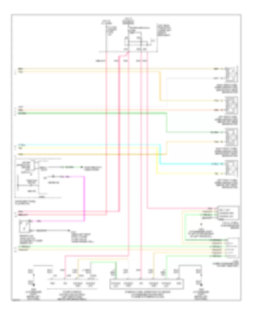
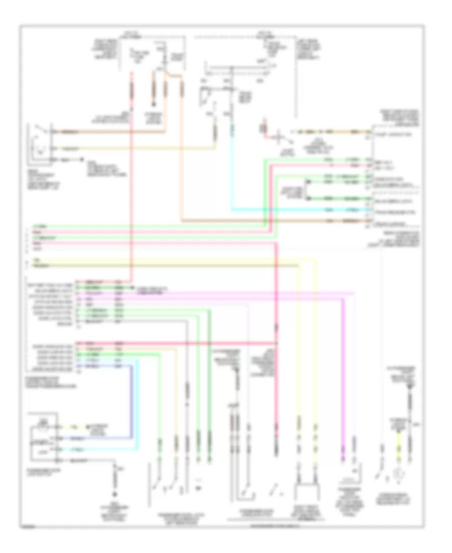
AIR CONDITIONING
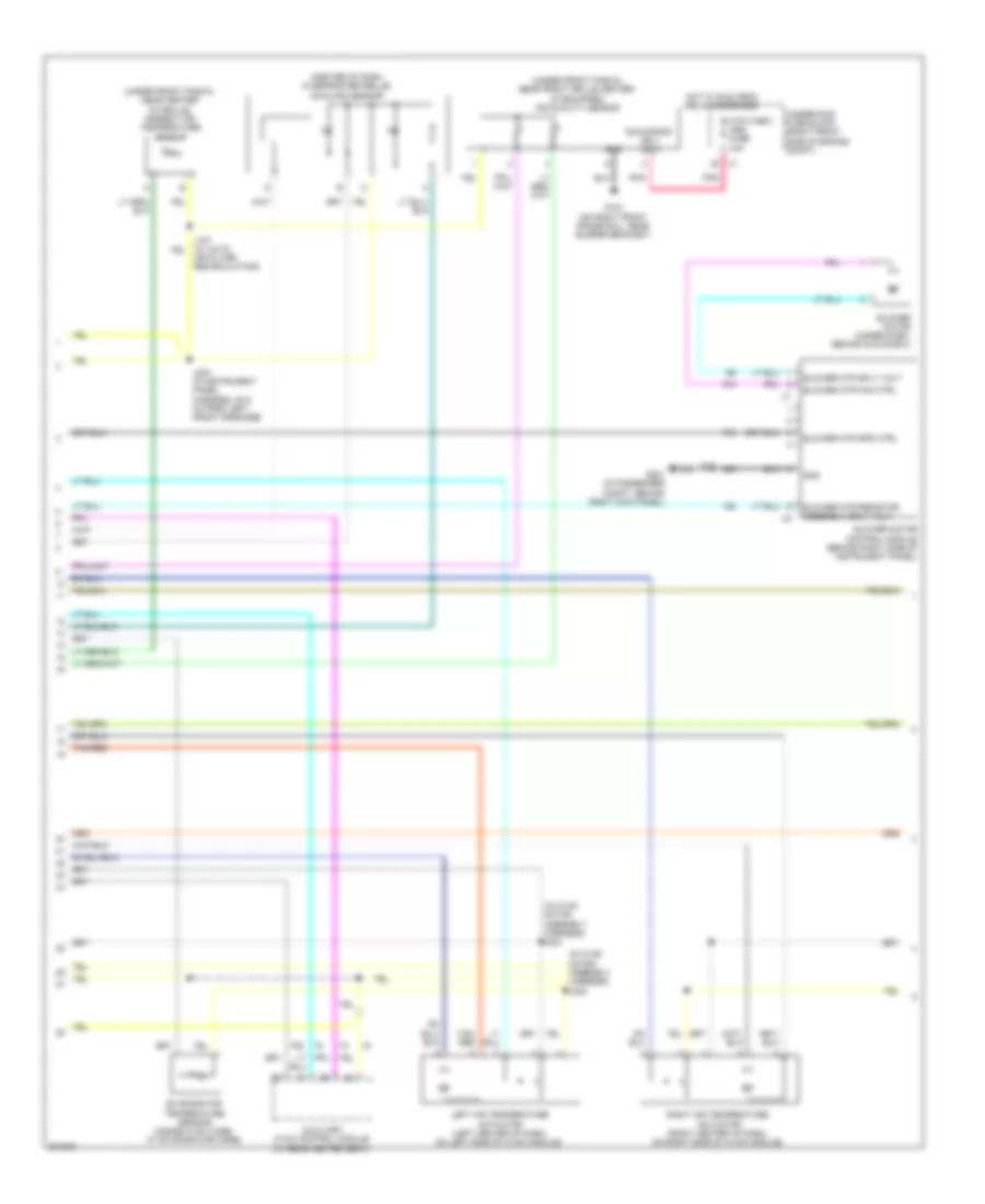
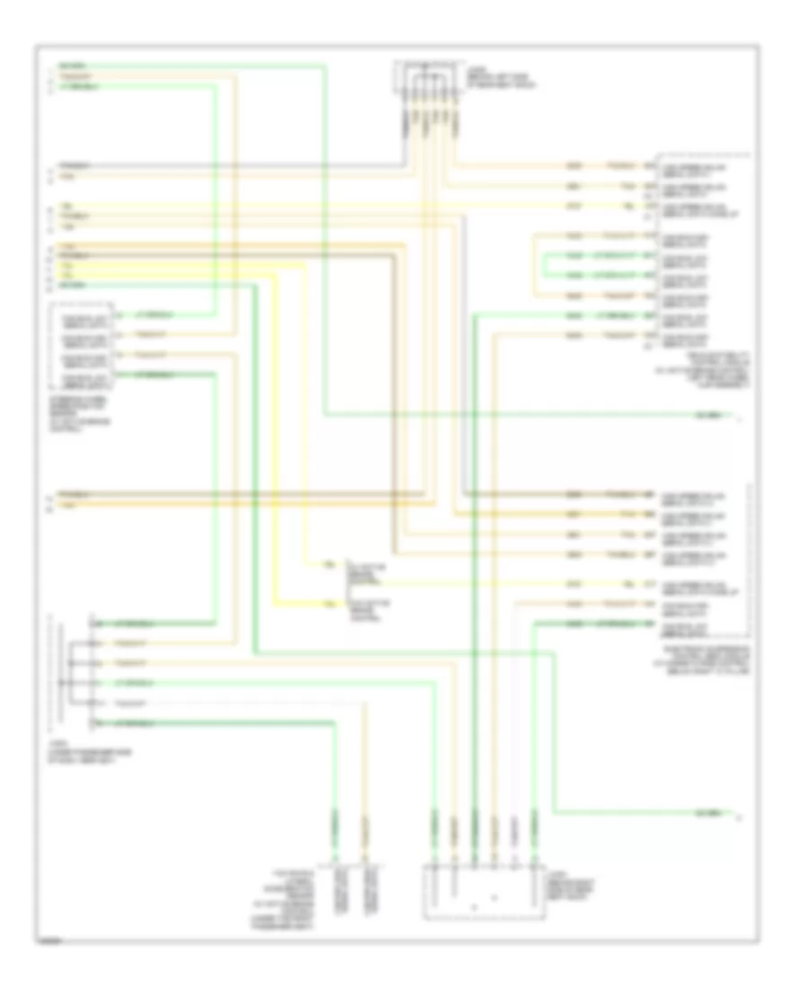
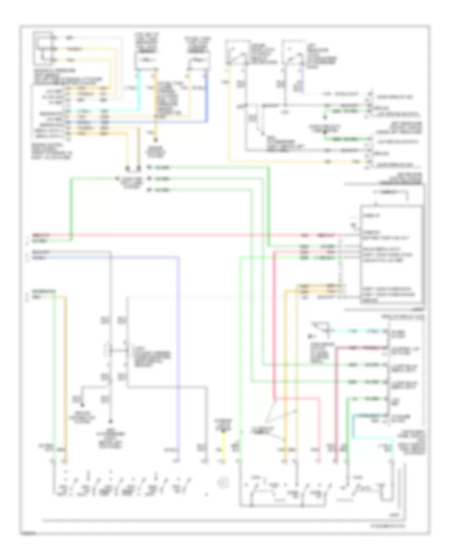
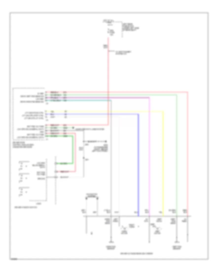
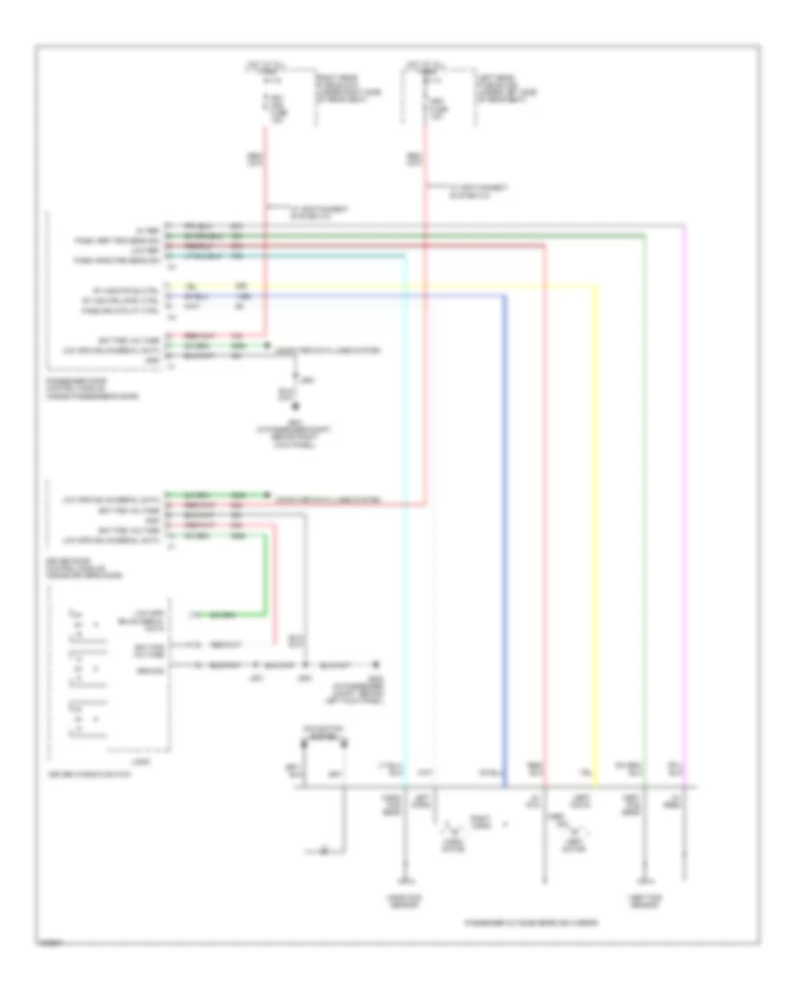
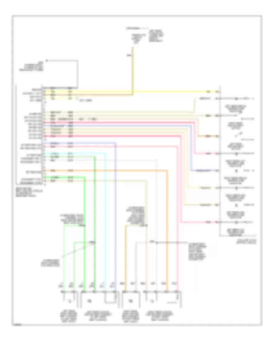
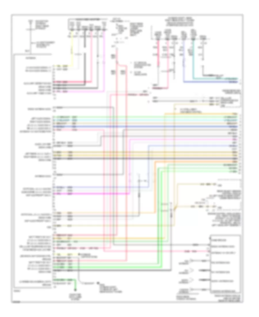
Automatic A/C Wiring Diagram (1 of 3) for Cadillac STS V 2009
 https://portal-diagnostov.com/license.html
Automotive Electricians Portal FZCO
Automotive Electricians Portal FZCO
https://portal-diagnostov.com/license.html
https://portal-diagnostov.com/license.html
Automotive Electricians Portal FZCO
Automotive Electricians Portal FZCO
List of elements for Automatic A/C Wiring Diagram (1 of 3) for Cadillac STS V 2009:
- (on dash right of steering column) inside air temperature (iat) sensor
- 5v ref
- A/c refrigerant low temp sens sig
- Air quality hc sens sig
- Air quality nox sens sig
- Air temp dr ctrl
- Ambient air temp sens sig
- Ambient light sens sig
- Auxiliary air temp dr ctrl
- Auxiliary air temp dr position sig
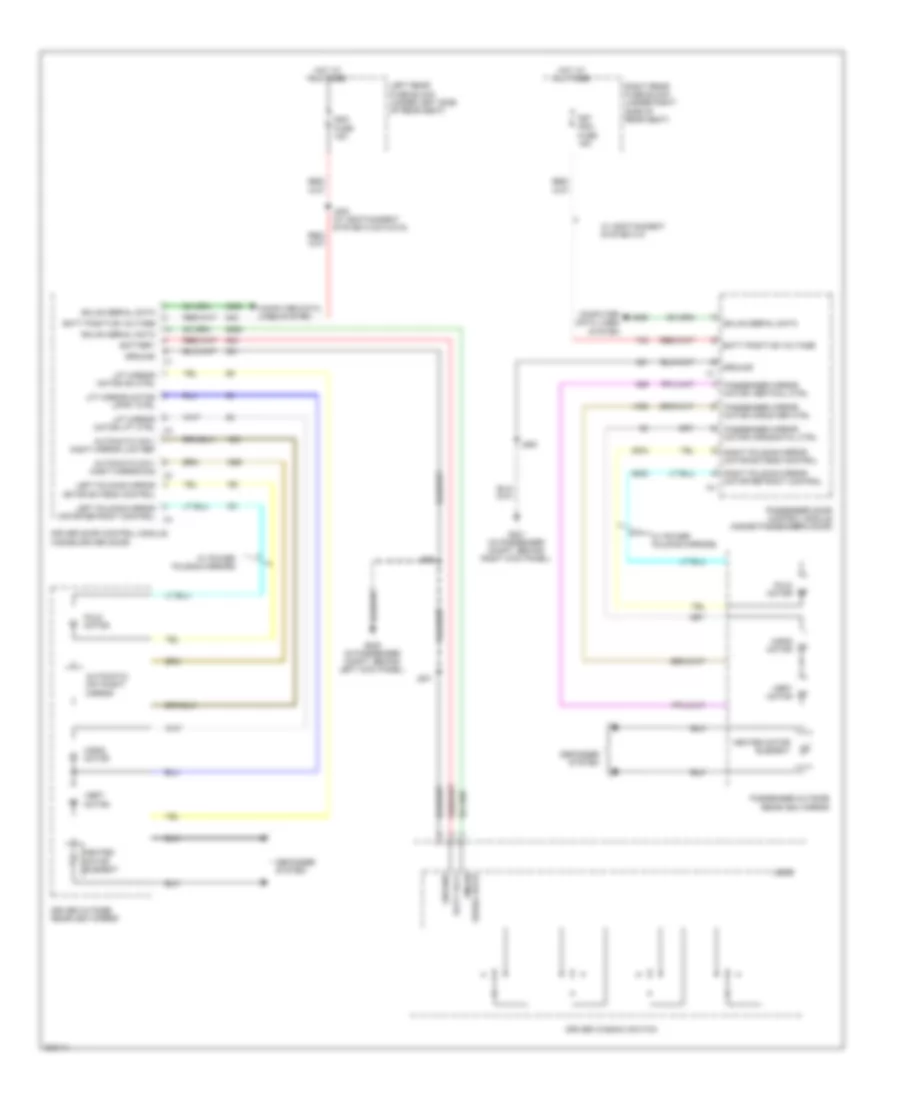
- Auxiliary air temperature actuator (left center of dash, on lower left side of hvac module)
- Auxiliary mode actuator (inside center console, on right rear side)
- Auxiliary mode dr position sig
- Batt positive volt
- Blower mtr spd ctrl
- Blwr fuse 40a
- Ccp fuse 10a
- Ccp/ rly coils fuse 10a
- Computer data lines system
- Drv air temp dr position sig
- Drv sunload sens sig
- Frt blwr relay
- G201 (in passenger compt, behind right kick panel)
- Gnd
- Hot at all times
- Hot w/ run crnk relay energized
- Hvac control module (center of dash, below radio)
- Ign 3 vlot
- Inside air temp sens assembly ctrl
- Inside air temp sens sig
- Interior lights system
- J210
- J211 (in dash harness, 28 cm from x214)
- Led backlight dimming ctrl
- Low ref
- Low spd gmlan serial data
- Medium 2 blower mtr ctrl
- Medium 3 blower mtr ctrl
- Medium blower mtr ctrl
- Mode dr ctrl
- Nca
- Pass air temp dr position sig
- Pass sunload sens sig
- Pnk
- Rear mode dr ctrl a
- Rear mode mtr low ref
- Recirculation actuator (on hvac module, left of blower motor)
- Recirculation door ctrl
- Recirculation door position sig
- Right air temp dr ctrl a
- Run/crank ign 1 volt
- Tan
- Tan/red
- Underhood fuse block (right front side of engine compt)
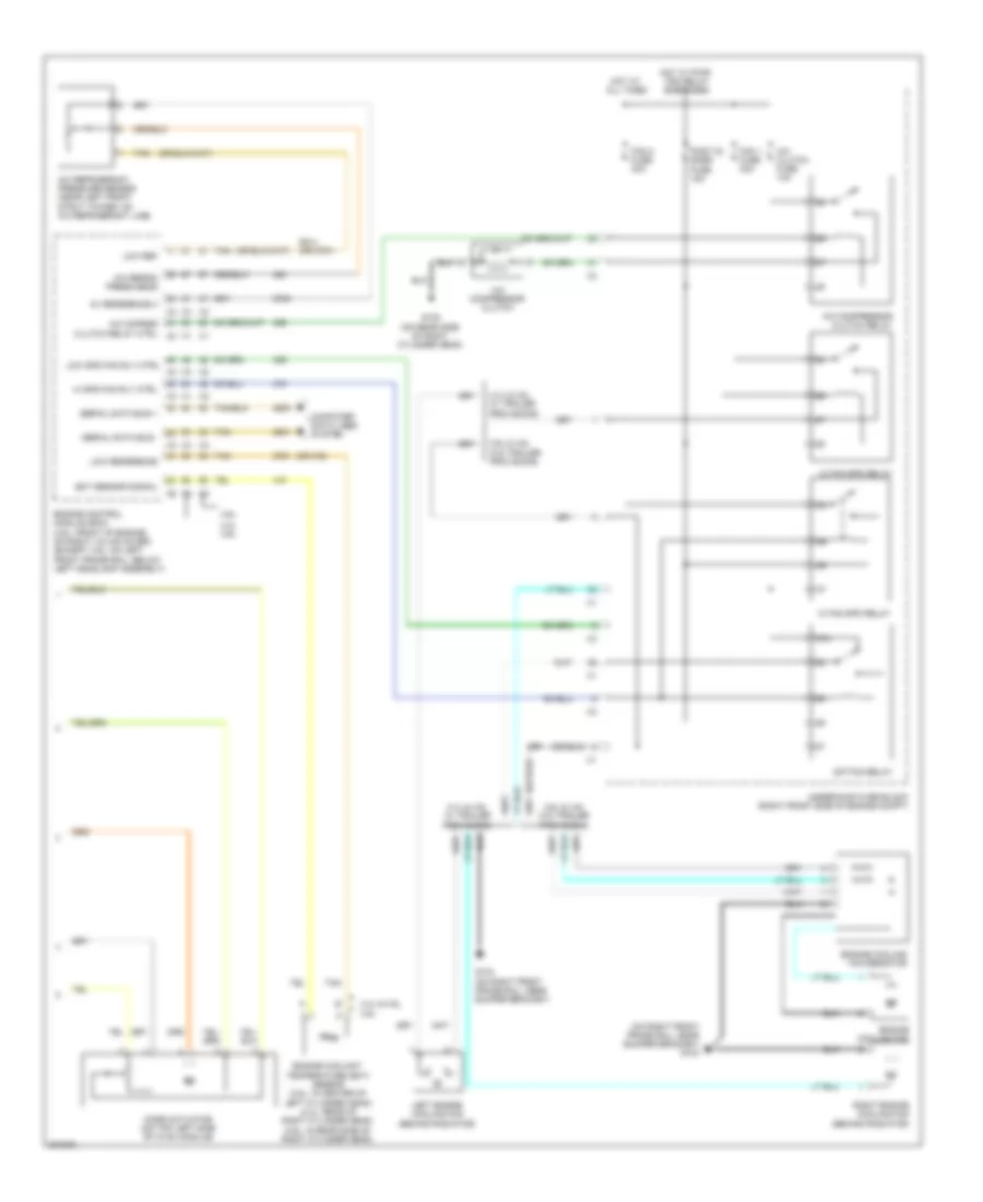
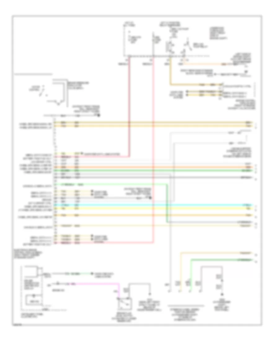
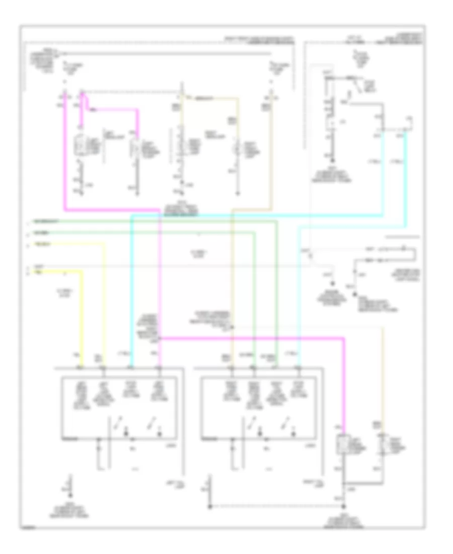
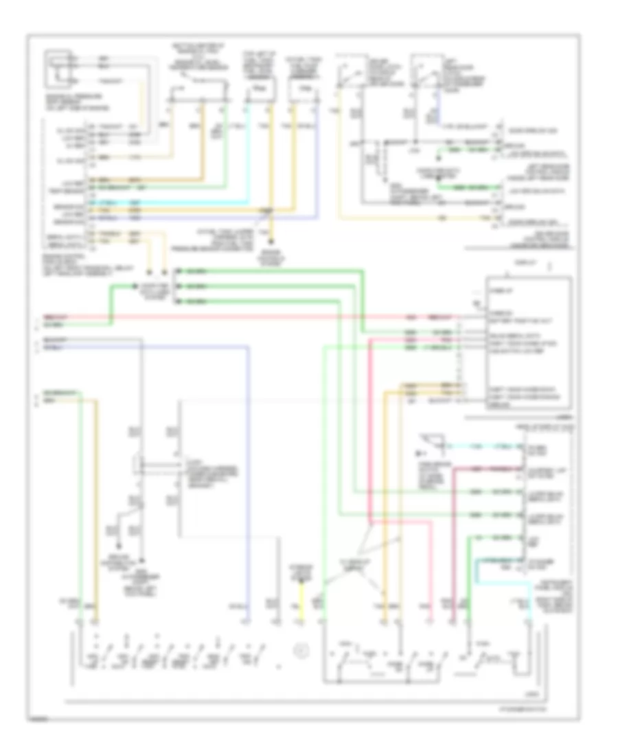
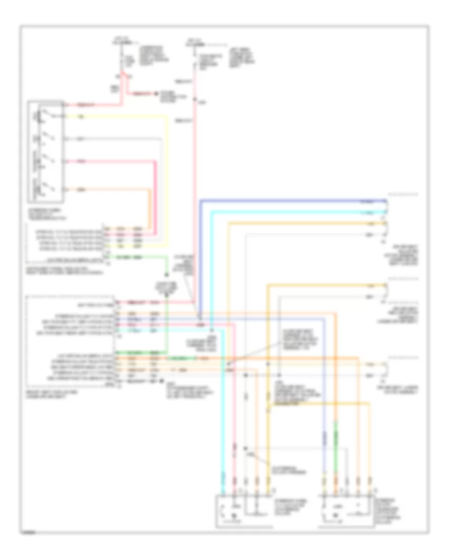
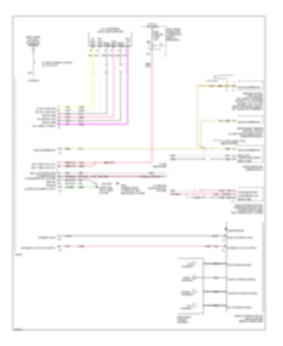
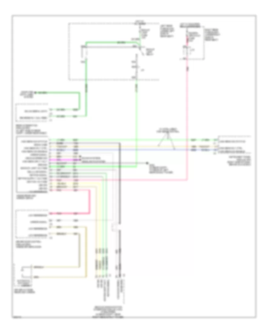
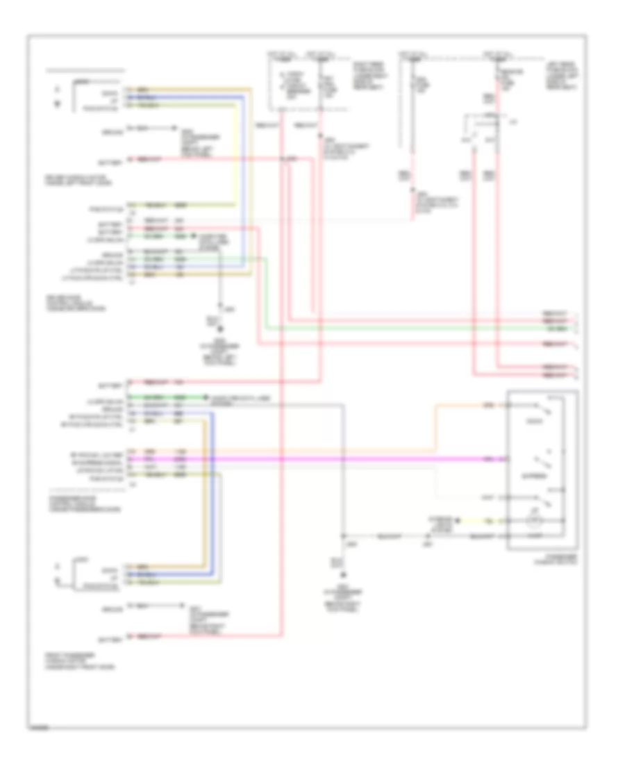
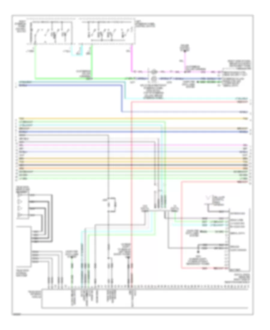
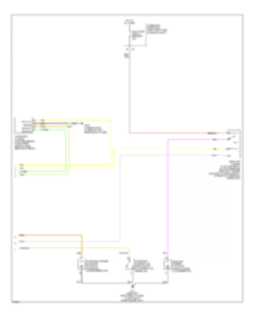
Automatic A/C Wiring Diagram (2 of 3) for Cadillac STS V 2009
List of elements for Automatic A/C Wiring Diagram (2 of 3) for Cadillac STS V 2009:
- (center of dash, in defroster grille) sunload sensor
- (in hvac motor assembly harness) j222
- (in hvac motor assembly harness) j223
- (under front fascia, near center of grille) ambient air temperature sensor
- (under front fascia, near front grille center) (if equipped) air quality sensor
- Air filter recirculating)
- Auxiliary hvac control module (w/ rear heated seat)
- Blower motor (under dash, behind glove box)
- Blower motor control module (behind right side of instrument panel)
- Blower mtr fan ctrl
- Blower mtr resistor assembly sply volt
- Blower mtr spd ctrl
- Blower mtr sply volt
- Evaporator temperature sensor (inside hvac case, at evaporator core)
- G104 (on right front frame rail, near bumper bracket)
- G201 (in passenger compt, behind right kick panel)
- Gnd
- Hot w/ run crnk relay energized
- Htd wash/ aqs fuse 10a
- J202 (in instrument panel harness, 50.5 cm from left front speaker)
- J212
- Left air temperature actuator (left center of dash, on left side of hvac module)
- Pnk
- Right air temperature actuator (right center of dash, on right side of hvac module)
- Run/crank ign 1 volt
- Tan/ red
- Tan/red
- Underhood fuse block (right front side of engine compt)
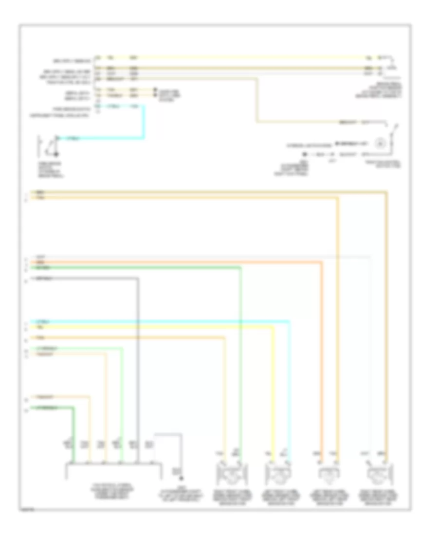
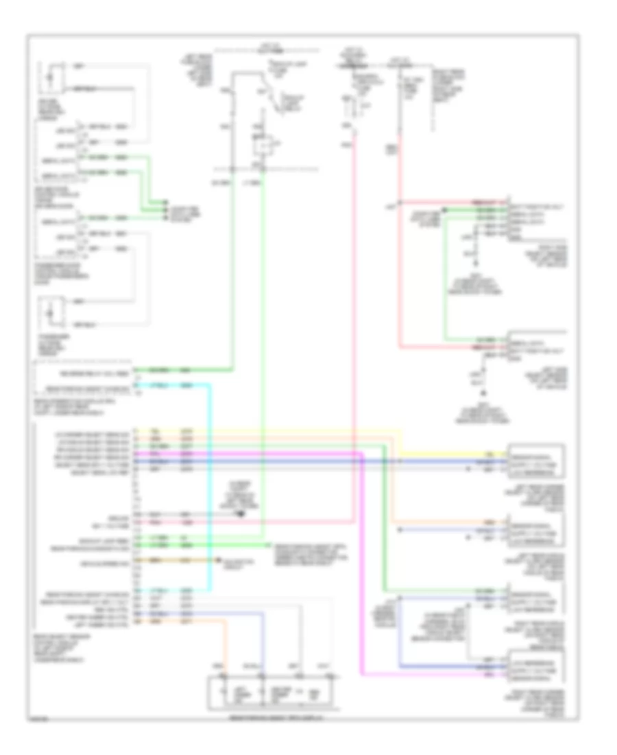
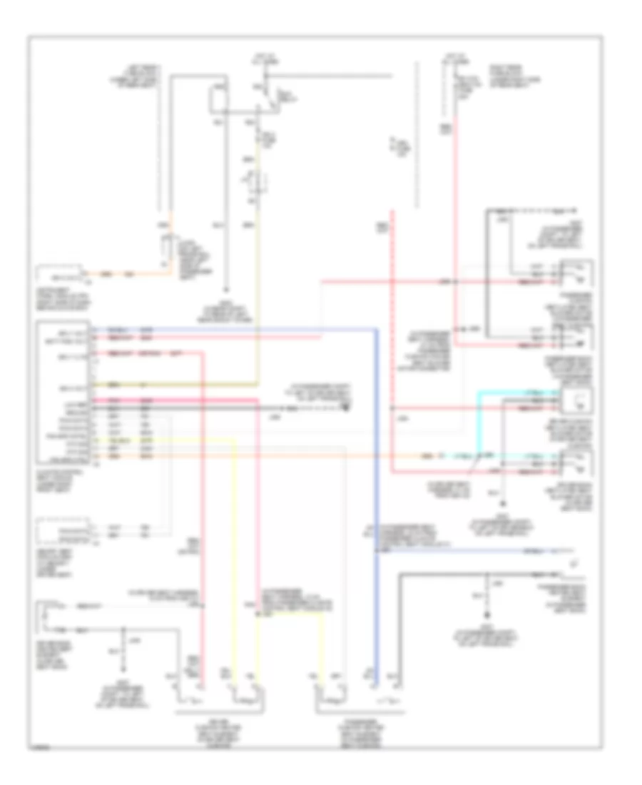
Automatic A/C Wiring Diagram (3 of 3) for Cadillac STS V 2009
List of elements for Automatic A/C Wiring Diagram (3 of 3) for Cadillac STS V 2009:
- (on right front frame rail, near bumper bracket) g104
- (or 2751)
- (or 476)
- 3.6l
- 3.6l & 4.6l w/o trailer provisions
- 4.4l & 4.6l
- 4.4l & 4.6l w/ trailer provisions
- 4.4l 3.6l
- 4.6l
- 5v reference 3
- 87a
- A/c clutch fuse 10a
- A/c cmprsr
- A/c compressor clutch
- A/c compressor clutch relay
- A/c refrig press sens
- A/c refrigerant pressure sensor (near left front strut tower, on a/c refrigerant line)
- Clutch relay ctrl x2
- Computer data lines system
- Ect sensor signal
- Engine control module (ecm) (3.6l: front of engine, on right valve cover) (except 3.6l: on left front frame rail, below left headlamp assembly)
- Engine coolant temperature (ect) sensor (3.6l: in center of left cylinder head) (4.4l: rear of right cylinder head) (4.6l: in rear side of right cylinder head)
- Engine cooling fan
- Engine cooling fan resistor
- Fan 1 fuse 30a
- Fan 2 fuse 30a
- G100 (on rear side of right cylinder head)
- G104 (on right front frame rail, near bumper bracket)
- Hi fan spd relay
- Hi spd fan rly ctrl
- Hot at all times
- Hot w/ pwr/ trn relay energized
- Left engine cooling fan (behind radiator)
- Lo fan spd relay
- Low ref
- Low reference
- Low spd fan rly ctrl
- Mode actuator (on top left side of hvac module)
- Post 02 snsr fuse 15a
- Right engine cooling fan (behind radiator)
- S/p fan relay
- Serial data bus +
- Serial data bus -
- Tan
- Underhood fuse block (right front side of engine compt)
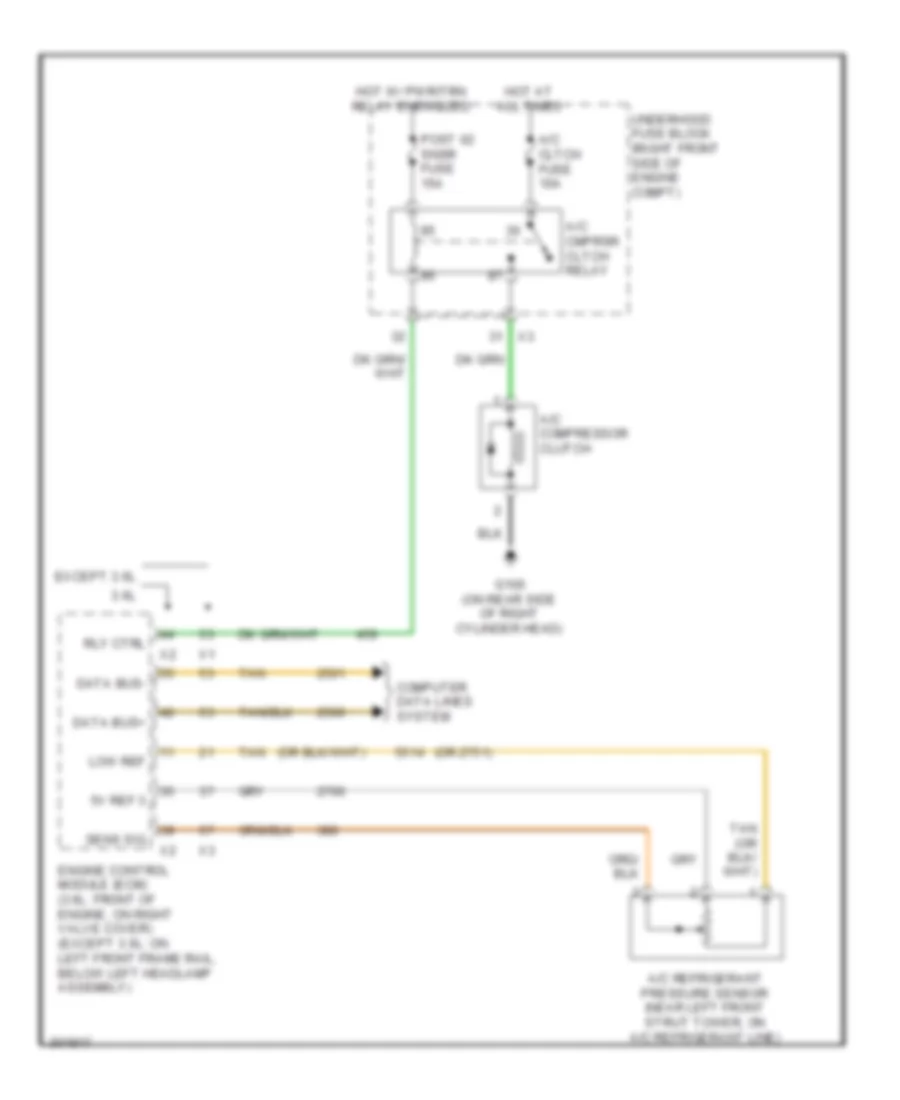
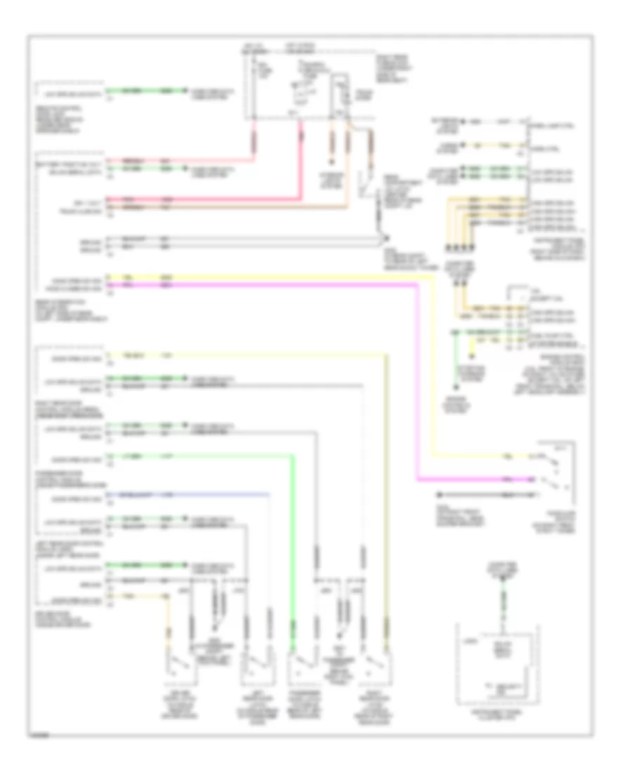
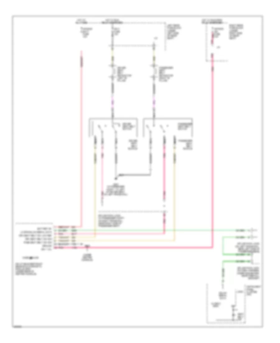
Compressor Wiring Diagram for Cadillac STS V 2009
List of elements for Compressor Wiring Diagram for Cadillac STS V 2009:
- (or 2751)
- 3.6l
- 5v ref 3
- A/c cltch fuse 10a
- A/c cmprsr cltch relay
- A/c compressor clutch
- A/c refrigerant pressure sensor (near left front strut tower, on a/c refrigerant line)
- Computer data lines system
- Data bus+
- Data bus-
- Engine control module (ecm) (3.6l: front of engine, on right valve cover) (except 3.6l: on left front frame rail, below left headlamp assembly)
- Except 3.6l
- G100 (on rear side of right cylinder head)
- Hot at all times
- Hot w/ pwr/trn relay energized
- Low ref
- Post 02 snsr fuse 15a
- Rly ctrl
- Sens sig
- Tan
- Underhood fuse block (right front side of engine compt)
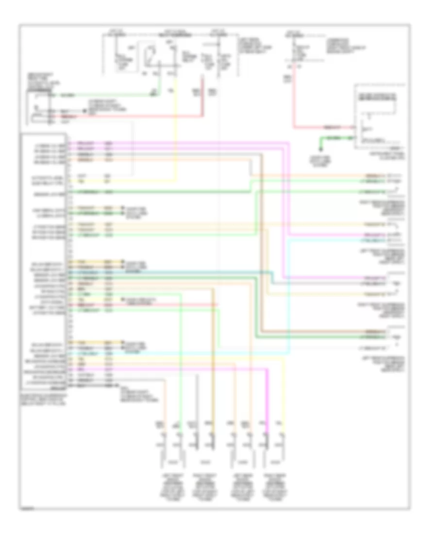
ANTI-LOCK BRAKES
Anti-lock Brakes Wiring Diagram, with VSC (1 of 2) for Cadillac STS V 2009
List of elements for Anti-lock Brakes Wiring Diagram, with VSC (1 of 2) for Cadillac STS V 2009:
- (left side of engine compt) auxiliary brake pump booster
- (not used)
- (on right front frame rail, near right front strut tower) g110
- 1-17
- 1-32
- 21-56
- 34-46
- 48-50
- 54-69
- Abs fuse 25a
- Abs mtr fuse 50a
- Batt positive volt
- Brake pressure modulator valve (bpmv)
- Brk vac pump fuse 15a (3.6l)
- Brk vac pump relay
- Can bus high serial data
- Can bus low serial data
- Computer data lines system
- Electronic brake control module (ebcm) (right front corner of engine compt)
- Electronic suspension control (esc) module (below right "c" pillar)
- Engine control module (ecm) (front of engine, on right valve cover)
- G110 (on right front frame rail, near right front strut tower)
- G201 (in passenger compt, behind right kick panel)
- G402 (in rear compt, to rear of left rear shock tower)
- Gnd
- Hi spd gmlan serial data (+)
- Hi spd gmlan serial data (-)
- Hot at all times
- Hot w/ pwr/trn relay energized
- Ign 1
- Instrument panel module (ipm)
- Interior lights system
- J311
- Jx404 (behind right side of rear seat back)
- Lf wheel spd sens low ref
- Lf wheel spd sens sig
- Lo spd gmlan serial data
- Lr wheel spd sens low ref
- Lr wheel spd sens sig
- Nca
- Pnk
- Rf wheel spd sens low ref
- Rf wheel spd sens sig
- Rr wheel spd sens low ref
- Rr wheel spd sens sig
- Serial data bus (+)
- Serial data bus (-)
- Serial data wake up
- Serial data wakeup
- Steering actr hi effort ctrl
- Steering actr lo effort ctrl
- Tan
- Traction control ind
- Traction control switch (tcs)
- Traction ctrl sw sig 2 x3
- Underhood fuse block (right front side of engine compt)
- Vacuum pump rly ctrl
- Variable effort steering actuator (in left rear engine compt, on steering rack)
- Vehicle stability control module (left rear wheel hub assembly)
Anti-lock Brakes Wiring Diagram, with VSC (2 of 2) for Cadillac STS V 2009
List of elements for Anti-lock Brakes Wiring Diagram, with VSC (2 of 2) for Cadillac STS V 2009:
- (near left front strut tower, at bottom of inside fender well)
- Abs ind
- Brake fluid level switch (in master cylinder reservoir)
- Brake ind
- Can bus high
- Can bus low
- Computer data lines system
- Driver information center (dic) display
- G101
- G200 (in passenger compt, behind left kick panel)
- G307 (in passenger compt, to left of driver seat, on left frame rail)
- Gnd
- Hot at all times
- Hot w/ run relay energized
- Ign
- Ign 1 volt
- Instrument panel cluster (ipc)
- J/c
- Jx204 (under passenger side of dash, near g201)
- Left front wheel speed sensor (wss) (behind left front brake rotor)
- Left rear fuse block (under left side of rear seat)
- Left rear wheel speed sensor (wss) (behind left rear brake rotor)
- Logic
- Pnk
- Power steering control module (pscm) (left side of dash, above park brake pedal)
- Right front wheel speed sensor (wss) (behind right front brake rotor)
- Right rear wheel speed sensor (wss) (behind right rear brake rotor)
- Rim/rpa/isrvm/clm fuse 10a
- S10
- S22
- S23
- S24
- Serial data
- Steering wheel speed/position sensor (in passenger compartment, at base of steering column)
- Tan
- Traction off ind
- Tv/vics/ afs/scm fuse 10a
- Yaw & lateral accelerometer sensor
Anti-lock Brakes Wiring Diagram, without VSC (1 of 2) for Cadillac STS V 2009
List of elements for Anti-lock Brakes Wiring Diagram, without VSC (1 of 2) for Cadillac STS V 2009:
- (left side of engine compt) auxiliary brake booster pump
- (on right front frame rail, near right front strut tower) g110
- (right rear side of engine block, near starter) g112
- Abs fuse 25a
- Abs ind
- Abs mtr fuse 50a
- Act hi effort ctrl
- Battery positive volt
- Brake fluid level switch (in master cylinder reservoir)
- Brake ind
- Brake pressure modulator valve (bpmv)
- Brk vac pump fuse 15a (3.6l)
- Brk vac pump relay
- Can bus hi serial data
- Can bus lo serial data
- Computer data lines system
- Driver information center (dic) display
- Electronic brake control module (ebcm) (right front corner of engine compt)
- Engine control module (ecm) (front of engine, on right valve cover)
- G101 (near left front strut tower, at behind of inside fender well)
- G200 (in passenger compt, behind left kick panel)
- Ground
- Hot at all times
- Hot w/ pwr/trn relay energized
- Ign
- Instrument panel cluster (ipc)
- Lf wheel spd sens low ref
- Logic
- Low effort ctrl
- Motor control
- Nca
- Serial data
- Serial data (+) (1)
- Serial data (-) (1)
- Serial data bus (+)
- Serial data bus (-)
- Serial data wake up
- Steering wheel speed/ position sensor (in passenger compt, at base of steering column)
- Tan
- Underhood fuse block (right front side of engine compt)
- Vacuum pump rly ctrl
- Variable effort steering actuator (on left side of power steering gear)
- Wheel spd sens lo ref lr
- Wheel spd sens lo ref rr
- Wheel spd sens low ref rf
- Wheel spd sens sig lf
- Wheel spd sens sig rf
- Wheel spd sens signal lr
- Wheel spd sens signal rr
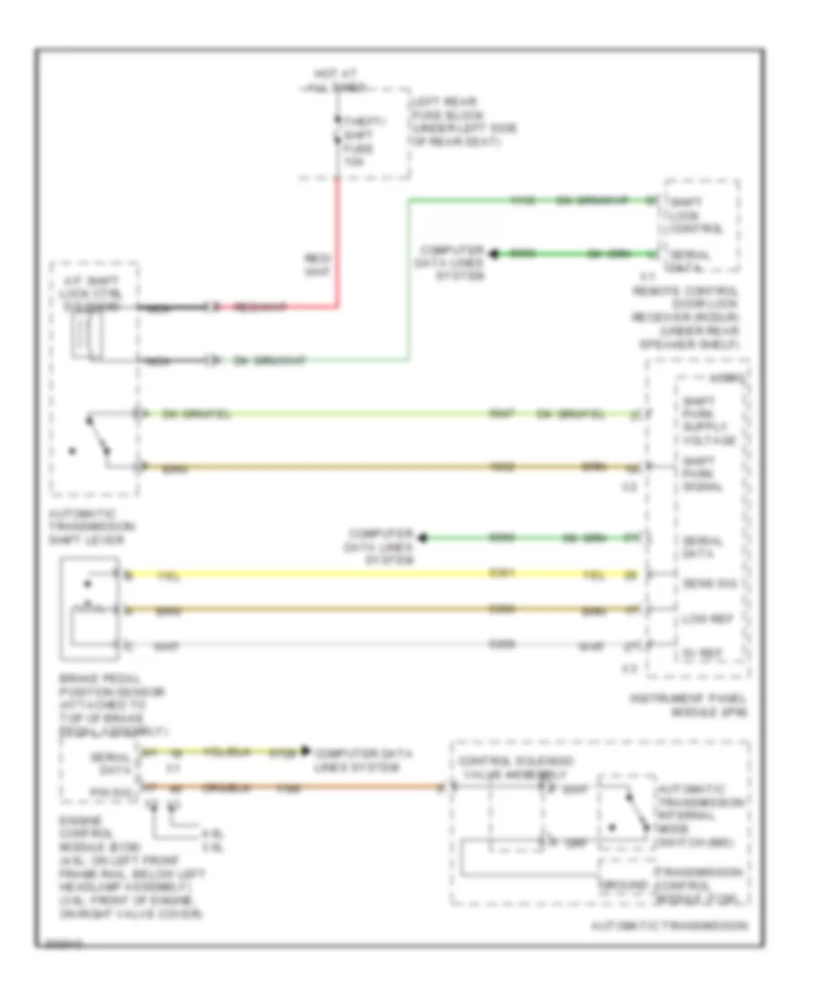
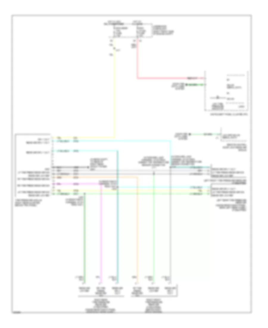
Anti-lock Brakes Wiring Diagram, without VSC (2 of 2) for Cadillac STS V 2009
List of elements for Anti-lock Brakes Wiring Diagram, without VSC (2 of 2) for Cadillac STS V 2009:
- Brake pedal position sensor (attached to top of brake pedal assembly)
- Computer data lines system
- G201 (in passenger compt, behind right kick panel)
- G307 (in passenger compt, to left of driver seat, on left frame rail)
- Instrument panel module (ipm)
- Interior lights system
- J311
- Left front wheel speed sensor (wss) (behind left front brake rotor)
- Left rear wheel speed sensor (wss) (behind left rear brake rotor)
- Park brake switch
- Park brake switch (at base of brake pedal)
- Right front wheel speed sensor (wss) (behind right front brake rotor)
- Right rear wheel speed sensor (wss) (behind right rear brake rotor)
- Serial data +
- Serial data -
- Tan
- Traction control switch (tcs)
- Traction ctrl sw sig 2
- Yaw rate & lateral acceleration sensor (under the front passenger seat)
ANTI-THEFT
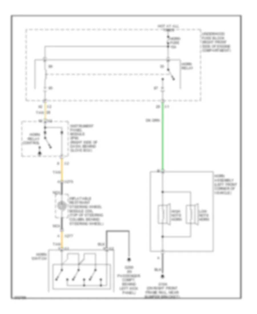
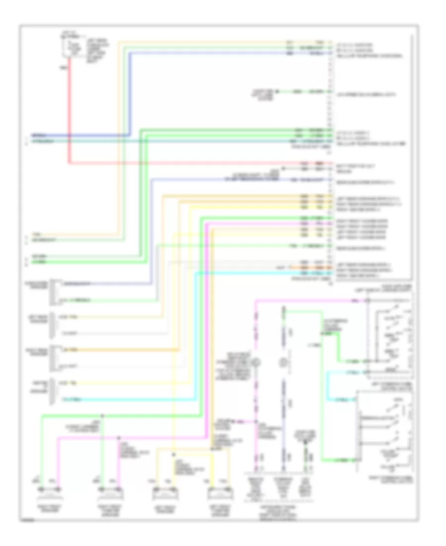
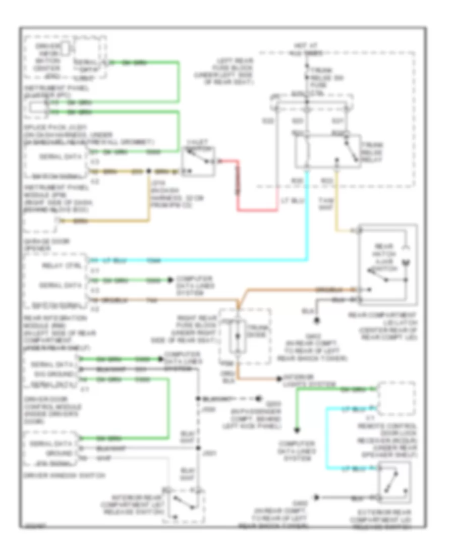
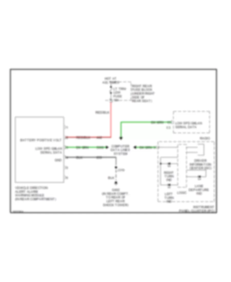
Anti-theft Wiring Diagram for Cadillac STS V 2009
List of elements for Anti-theft Wiring Diagram for Cadillac STS V 2009:
- 3.6l
- Battery positive volt
- Computer data lines system
- Door open sw sig
- Driver door control module (inside driver door)
- Driver door latch (in middle rear of driver door)
- Engine control module (ecm) (3.6l: front of engine, on right valve cover) (except 3.6l: on left front frame rail, below left headlamp assembly)
- Engine controls system
- Except 3.6l
- Exterior lights system
- Fd1
- Fd2
- Fuel pump ctrl
- G104 (on right front frame rail, near bumper bracket)
- G200 (in passenger compt, behind left kick panel)
- G201 (in passenger compt, behind right kick panel)
- G402 (in rear compt, to rear of left rear shock tower)
- Gmlan serial data
- Ground
- High spd gmlan+
- High spd gmlan-
- Hood ajar switch (on right front strut tower)
- Hood closed sw sig
- Hood open sw sig
- Horn ctrl
- Horns system
- Hot at all times
- Hot in run or crank
- Ign 1 volt
- Instrument panel cluster (ipc)
- Instrument panel module (ipm) (right side of dash, behind glove box)
- Interior lights system
- J/c
- J500
- J600
- J700
- J800
- Left rear door control module (lrdm) (inside left rear door)
- Left rear door latch (in middle rear of passenger door)
- Logic
- Low spd gmlan
- Low spd gmlan data
- Park lamp ctrl
- Passenger door control module (inside passenger's door)
- Passenger door latch (in middle rear of left rear door)
- Pnk
- Rear compartment lid latch (center rear of rear compt lid)
- Rear integration module (rim) (in left side of rear compt, under rear shelf)
- Remote control door lock receiver (rcdlr) (under rear speaker shelf)
- Right rear door control module (rrdm) (inside right rear door)
- Right rear door latch (in middle rear of right rear door)
- Right rear fuse block (under right side of rear seat)
- Rim fuse 10a
- Rim/rpa/ isrvm/clm fuse 10a s8
- S11
- Security ind
- Starter enable
- Starting/ charging system
- Tan
- Trunk ajar sig
- Trunk diode
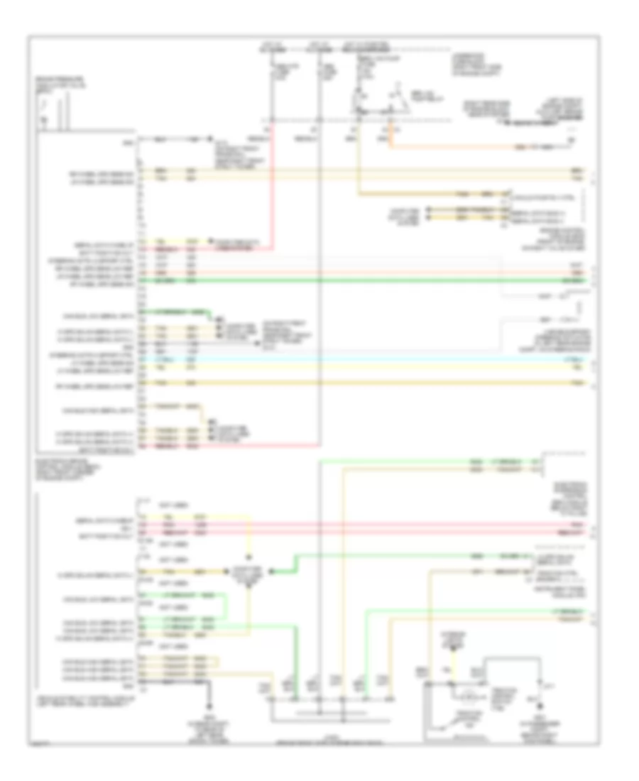
BODY CONTROL MODULES
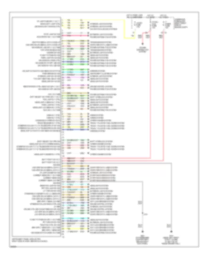
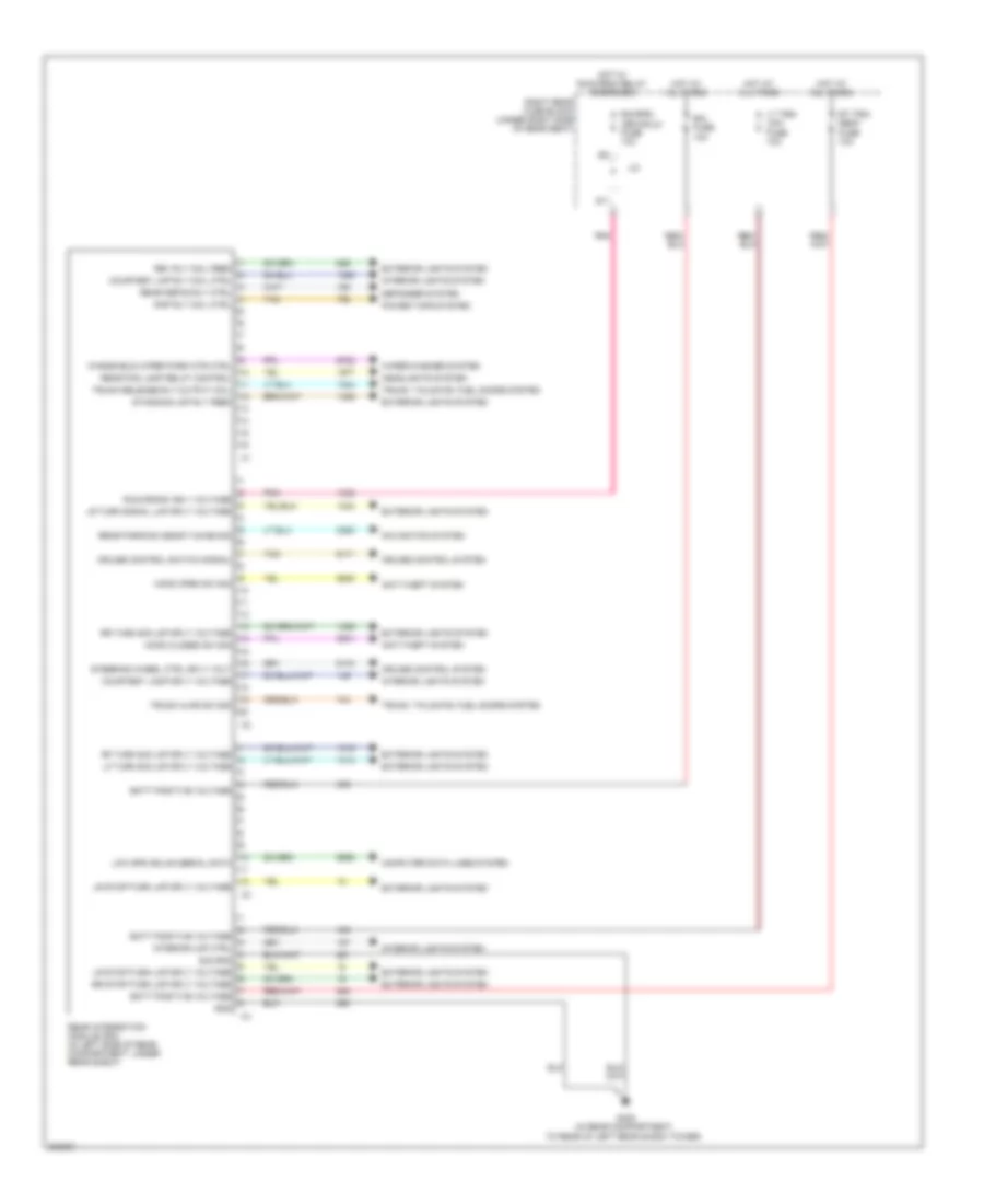
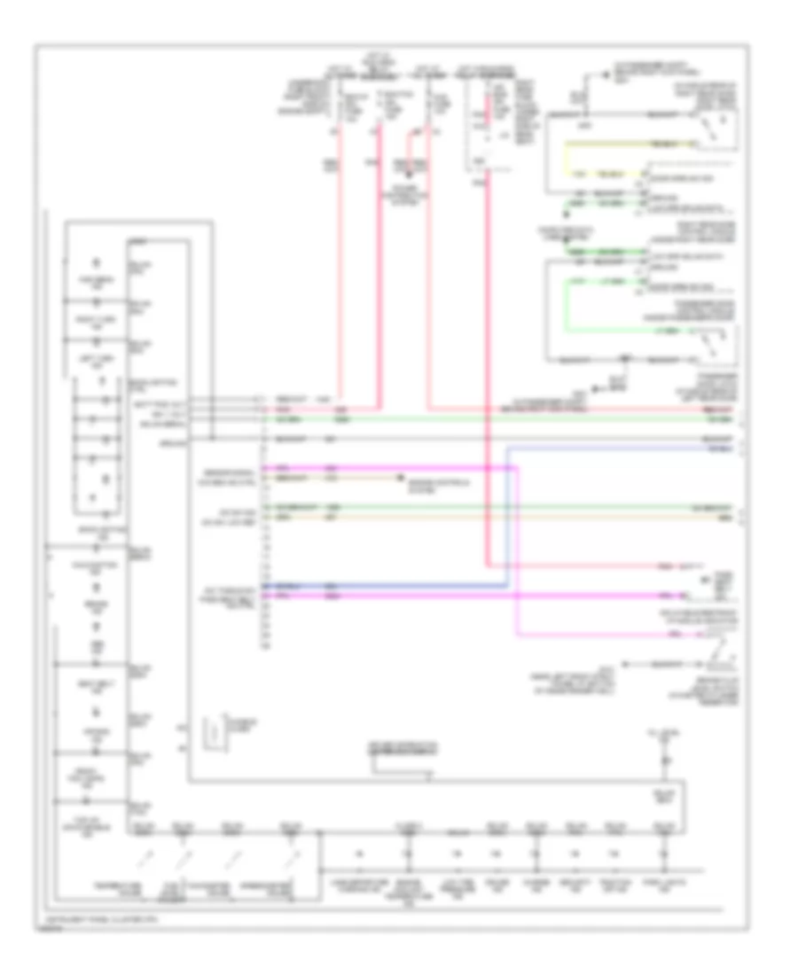
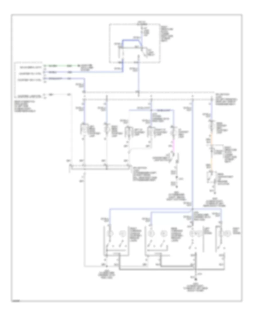
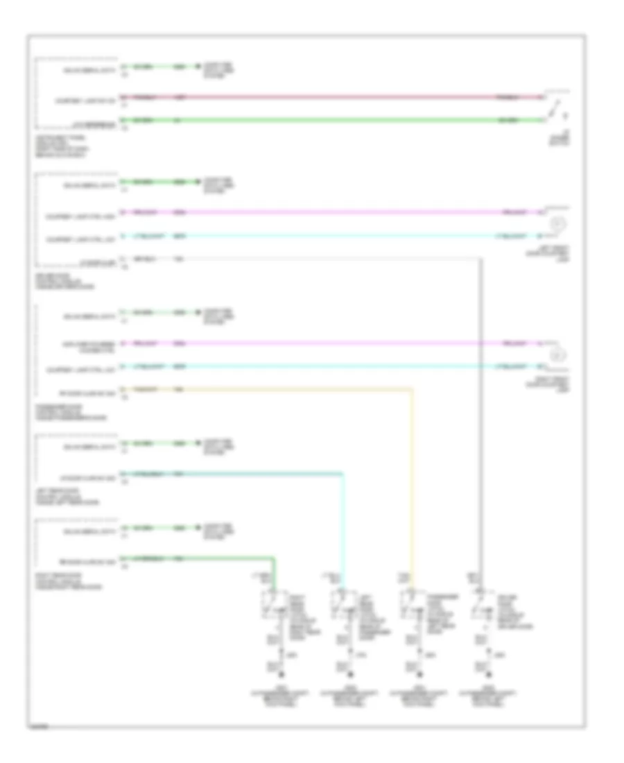
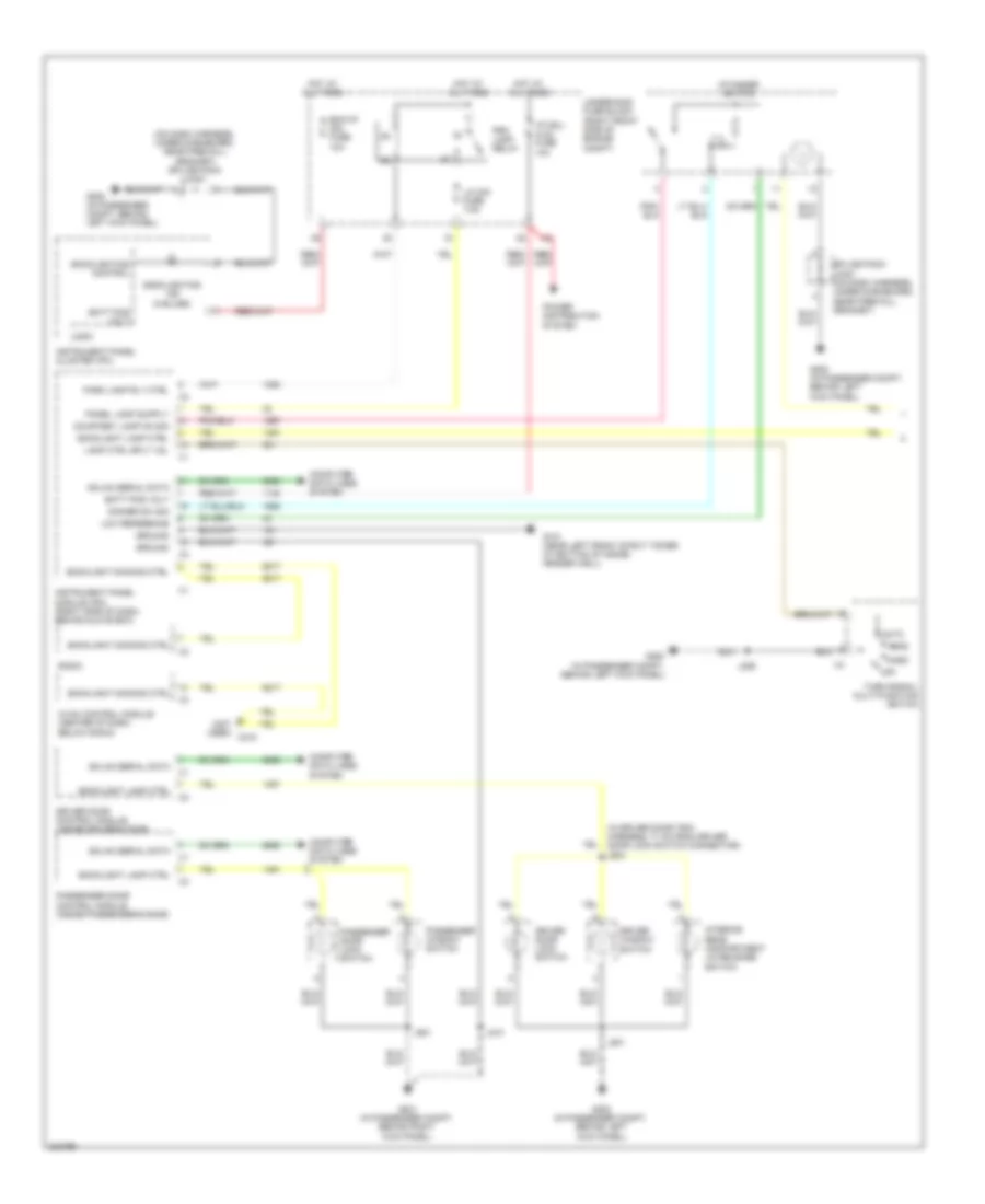
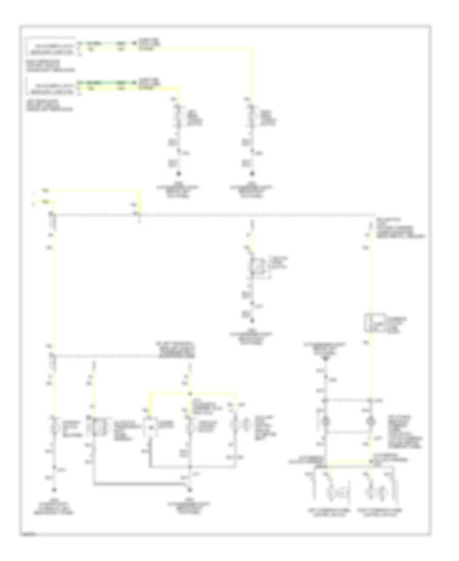
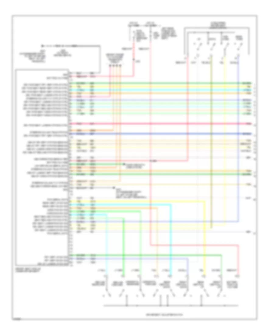
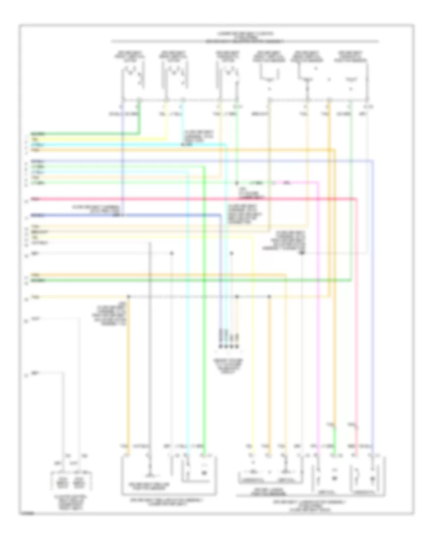
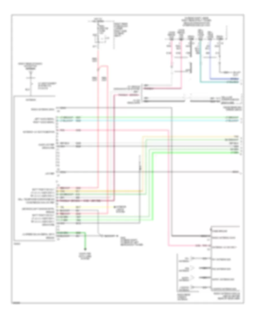
Instrument Panel Module Wiring Diagram for Cadillac STS V 2009
List of elements for Instrument Panel Module Wiring Diagram for Cadillac STS V 2009:
- 5v ref
- Acc voltage
- Anti-lock brakes system
- Backlight lamp ctrl
- Batt positive volt
- Computer data lines system
- Cruise control system
- Cruise ctrl set/coast/res/acc sw sig
- Current sens low ref
- Current sens sig
- Current sens sply voltage
- Ecm/tcm serial data wake up
- Exterior lights system
- Flash to pass sw sig
- Flash to pass sw sply voltage
- Fog lamp rly ctrl
- Frt fog lamp sw sig
- G101 (near left front strut tower, at bottom of inside fender well)
- G201 (in passenger compartment, behind right kick panel)
- Hazard sw sig
- Hdlamp automatic high beam dim status
- Headlamp automatic high beam dim enable
- Headlamp hi beam rly ctrl
- Headlamp low beam rly ctrl
- Headlamp on with wipers signal
- Headlamp sw on sig
- Headlamp washer rly ctrl
- Headlights system
- High spd gmlan serial data (+)
- High spd gmlan serial data (-)
- High spd gmlan serial data wake up
- Horn rly ctrl
- Horns system
- Hot at all times
- Hot w/ park lamp relay energized
- I/p lamp dimmer sw sig
- I/p lamp fuse sply volt 1
- I/p mdl/ aldl fuse 10a
- Ign mode sw acc led sig
- Ign mode sw led sply voltage
- Ign mode sw mode ctrl
- Ign mode sw off led sig
- Ign mode sw start led sig
- Ign mode switch mode voltage
- Instrument cluster system
- Instrument panel module (ipm) (right side of dash, behind glove box)
- Interior lamp sw on sig
- Interior lights system
- J210
- Led backlight dimming ctrl
- Lf turn sig sw sig
- Lic/dim fuse 7.5a
- Low spd gmlan serial data
- Mirrors system
- Navigation & sound systems
- Park brake sw sig
- Park lamp rly ctrl
- Park lamp sw on sig
- Pnk
- Power distribution system
- Rear fog lamp sw sig
- Remote radio ctrl head acc sply volt
- Rf turn sig sw sig
- Run ign 3 voltage
- Run/crank ign 1 voltage
- Shft select sw park sply volt
- Shift interlock system
- Shift select sw prk sig
- Sig gnd
- Starting/charging system
- Steering column radio ctrl sig
- Steering column tilt & telescope dn sw sig
- Steering column tilt & telescope fwd sw sig
- Steering column tilt & telescope rwd sw sig
- Steering column tilt & telescope up sw sig
- Stop lamp sw sig
- Tan
- Tap up/dn enable sig
- Traction ctrl sw sig
- Transmissions system
- Trunk release rly ctrl
- Trunk, tailgate, fuel doors system
- Twilight sentinel delay sig
- Underhood fuse block (right front side of engine compt)
- V/ check fuse 10a
- Windshield washer fluid lvl sens sig
- Windshield wiper sw sig 2
- Wiper/washer system
Rear Integration Module Wiring Diagram for Cadillac STS V 2009
List of elements for Rear Integration Module Wiring Diagram for Cadillac STS V 2009:
- Anti-theft system
- Batt positive voltage
- Computer data lines system
- Courtesy lamp sply voltage
- Courtesy lmp rly coil ctrl
- Cruise control switch signal
- Cruise control system
- Defogger system
- Exterior lights system
- G402 (in rear compartment, to rear of left rear shock tower)
- Gnd
- Headlights system
- Hood closed sw sig
- Hood open sw sig
- Hot at all times
- Hot w/ run/crnk relay energized
- Interior lights system
- Interior lmp ctrl
- J/c
- Lf turn sig lmp sply voltage
- Low spd gmlan serial data
- Lr stop/turn lmp sply voltage
- Lr turn signal lmp sply voltage
- Lt trn/ ldw fuse 10a
- Navigation system
- Pnk
- Power tops system
- Rap rly coil ctrl
- Rear defog rly ctrl
- Rear fog lamp relay control
- Rear integration module (rim) (in left side of rear compartment, under rear shelf)
- Rear parking assist chime sig
- Rev rly coil feed
- Rf turn sig lmp sply voltage
- Right rear fuse block (under right side of rear seat)
- Rim fuse 10a
- Rim/rpa/ isrvm/clm fuse 10a
- Rr stop/turn lmp sply voltage
- Rr turn sig lmp sply voltage
- Rt trn/ sbza fuse 10a
- Run/crank ign 1 voltage
- S11
- Sig gnd
- Standing lmp rly feed
- Steering wheel ctrl sply volt
- Tan
- Trunk ajar sw sig
- Trunk release rly output coil
- Trunk, tailgate, fuel doors system
- Windshield wiper park mtr ctrl
- Wiper/washer system
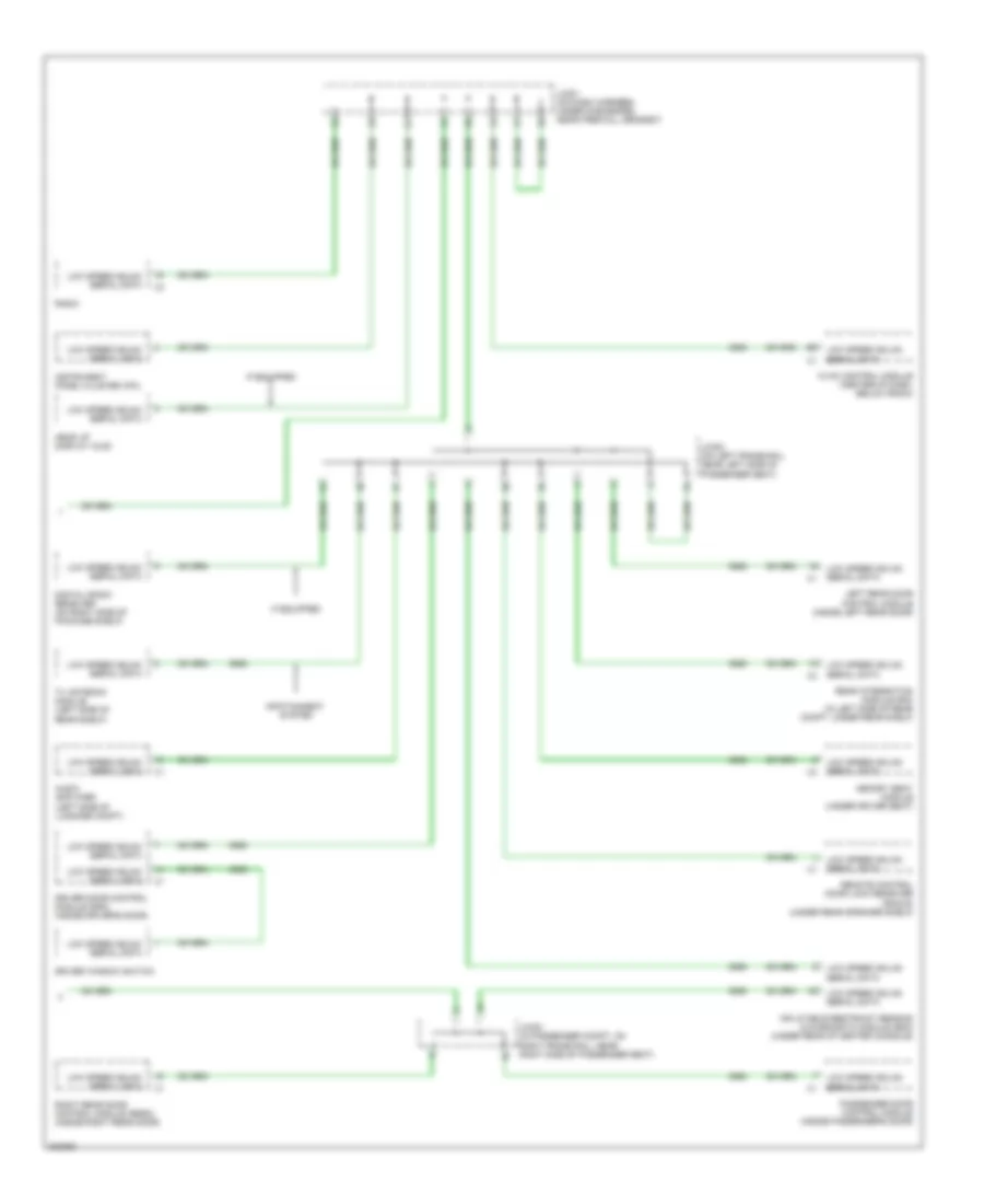
COMPUTER DATA LINES
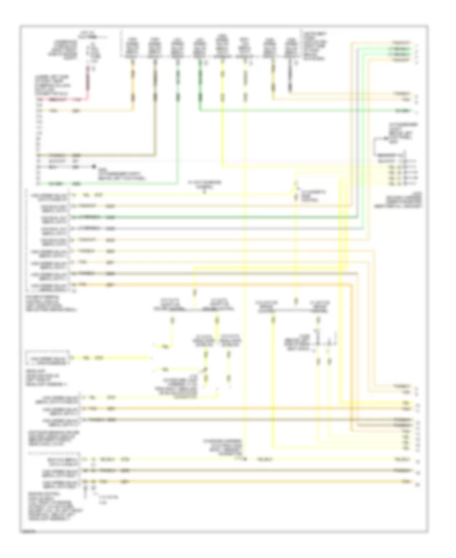
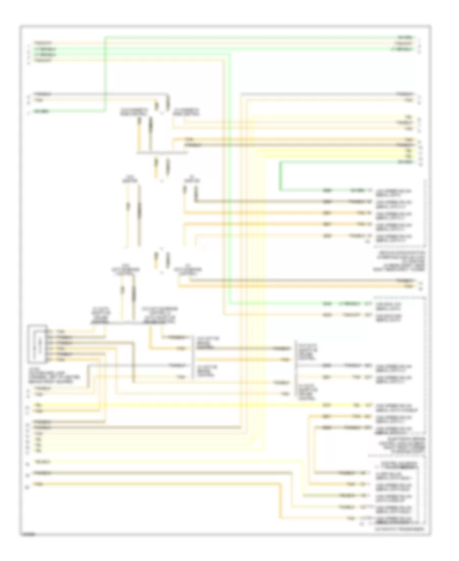
Computer Data Lines Wiring Diagram (1 of 4) for Cadillac STS V 2009
List of elements for Computer Data Lines Wiring Diagram (1 of 4) for Cadillac STS V 2009:
- (in engine harness, 19 cm from ho2s bank 1 sensor 1 connector) j113
- (in passenger compt, behind left kick panel) g200
- (under left side of dash, near steering column) data link connector (dlc)
- 3.6l
- 4.4l & 4.6l
- Can bus high serial data
- Can bus low serial data
- Distance sensing cruise control (dscc) module (behind front fascia, near hood latch)
- Ecm/ tcm serial data wake up
- Ecm/tcm serial data wake up
- Engine control module (ecm) (3.6l: front of engine, on right valve cover) (except 3.6l: on left front frame rail, below left headlamp assembly)
- G200 (in passenger compt, behind left kick panel)
- Headlamp leveling module (left side of headlamp assembly)
- High speed gmlan data wake up
- High speed gmlan serial data (+)
- High speed gmlan serial data (-)
- High speed gmlan serial data +
- High speed gmlan serial data -
- High speed gmlan serial data bus +
- High speed gmlan serial data bus -
- High speed gmlan serial data wake up
- Hot at all times
- Instrument panel module (ipm) (right side of dash, behind glove box)
- Ip/ mdl/ aldl fuse 10a
- J116 (in forward lamp harness, 31 cm from right headlamp leveling actuator connector)
- Jx201 (on dash harness, under dashboard, near firewall grommet)
- Jx405 (behind left side of rear seat back)
- Low speed gmlan serial data
- Power steering control module (left side of dash, above park brake pedal)
- Tan
- Underhood fuse block (right front side of engine compt)
- W/ active brake control
- W/ auto adaptive cruise control
- W/ auto headlamps leveling
- W/ magnetic ride control
- W/o active brake control
- W/o auto adaptive cruise control
- W/o auto headlamps leveling
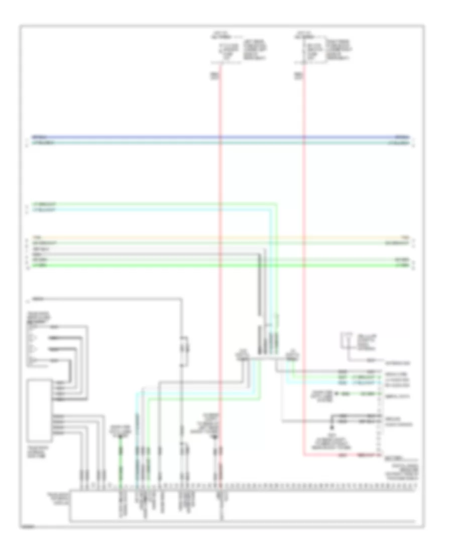
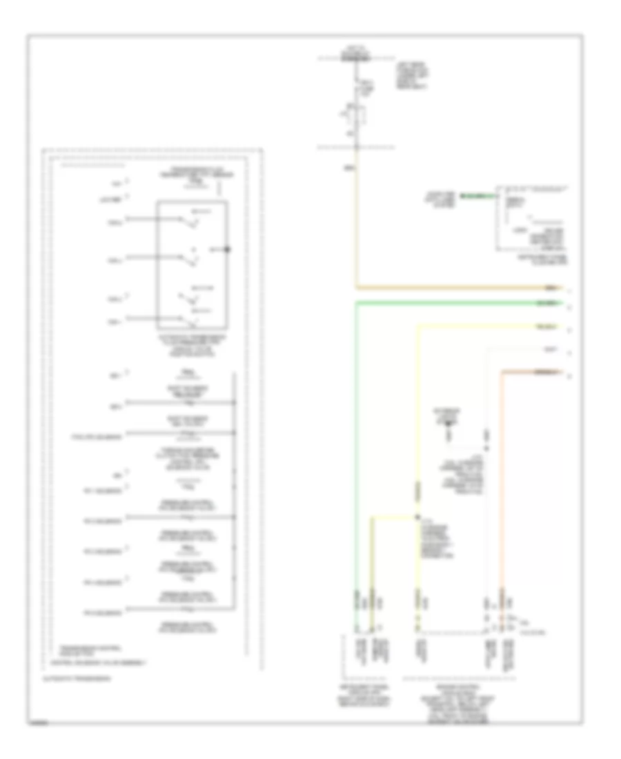
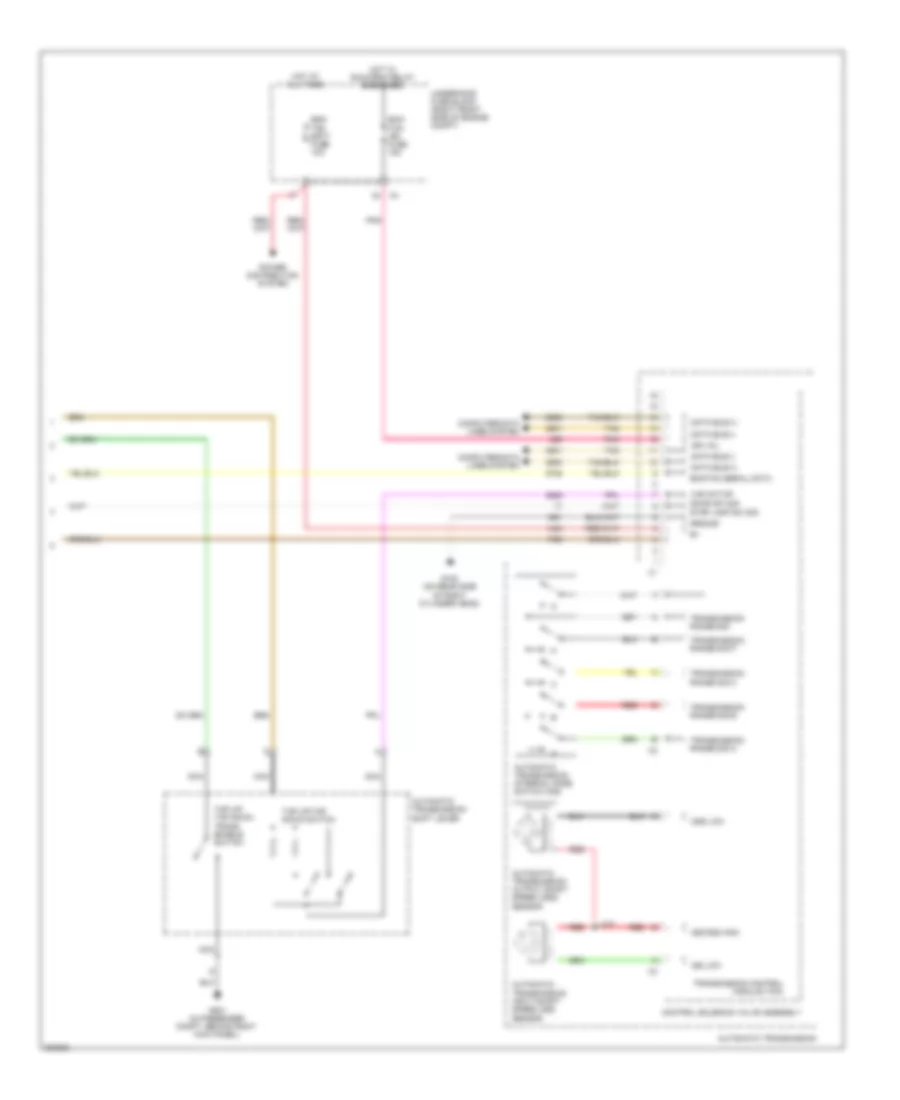
Computer Data Lines Wiring Diagram (2 of 4) for Cadillac STS V 2009
List of elements for Computer Data Lines Wiring Diagram (2 of 4) for Cadillac STS V 2009:
- Automatic transmission
- Can bus high serial data
- Can bus low serial data
- Control solenoid valve assembly
- Electronic brake control module (ebcm) (right front corner of engine compt)
- Hi spd gmlan serial data bus +
- High speed gmlan data wake up
- High speed gmlan serial data (+)
- High speed gmlan serial data (-)
- High speed gmlan serial data bus +
- High speed gmlan serial data bus -
- High speed gmlan serial data wakeup
- Jx100 (on forward lamp harness, left of center, behind front bumper)
- Low speed gmlan serial data
- Tan
- Vehicle communication interface module (vcim) (w/ onstar) (in rear compt, near right rear strut tower)
- W/ active brake control
- W/ auto adaptive cruise control
- W/ magnetic ride control
- W/ onstar
- W/o active brake control
- W/o active brake control & auto adaptive cruise control
- W/o auto adaptive cruise control
- W/o magnetic ride control
- W/o onstar
Computer Data Lines Wiring Diagram (3 of 4) for Cadillac STS V 2009
List of elements for Computer Data Lines Wiring Diagram (3 of 4) for Cadillac STS V 2009:
- (under passenger side
- Can bus high serial data
- Can bus low serial data
- Electronic suspension control (esc) module (w/ magnetic ride control) (below right "c" pillar)
- High speed gmlan serial data (+)
- High speed gmlan serial data (-)
- High speed gmlan serial data +
- High speed gmlan serial data -
- High speed gmlan serial data wake up
- Jx204
- Jx404 (behind right side of rear seat back)
- Jx405 (behind left side of rear seat back)
- Of dash, near g201)
- Serial data can bus high
- Steering wheel speed/position sensor (w/ active brake control)
- Tan
- Vehicle stability control module (w/ active brake control) (left rear wheel hub assembly)
- W/ active brake control
- W/o active brake control
- Yaw rate & lateral acceleration sensor (w/ active brake control) (under the front passenger seat)
Computer Data Lines Wiring Diagram (4 of 4) for Cadillac STS V 2009
List of elements for Computer Data Lines Wiring Diagram (4 of 4) for Cadillac STS V 2009:
- Audio amplifier (left side of luggage compt)
- B5 low speed gmlan serial data x1
- Digital radio receiver (on right side of package shelf)
- Driver door control module (ddm) (inside driver's door)
- Driver window switch
- Head up display (hud)
- Hvac control module (center of dash, below radio)
- If equipped
- Inflatable restraint sensing & diagnostic module (sdm) (under rear of center console)
- Infotainment system
- Instrument panel cluster (ipc)
- Jx201 (on dash harness, under dashboard, near firewall grommet)
- Jx300 (on left frame rail, near left side of passenger seat)
- Jx303 (in passenger compt, on right frame rail, near right side of passenger seat)
- L low speed gmlan serial data x1
- Left rear door control module (inside left rear door)
- Low speed gmlan serial data
- Low speed gmlan serial data x1
- Low speed gmlan serial data x3
- Memory seat module (under driver seat)
- Passenger door control module (inside passenger's door)
- Radio
- Rear integration module (rim) (in left side of rear compt, under rear shelf)
- Remote control door lock receiver (rcdlr) (under rear speaker shelf)
- Right rear door control module (rrdm) (inside right rear door)
- Tv antenna module (left side of rear shelf)
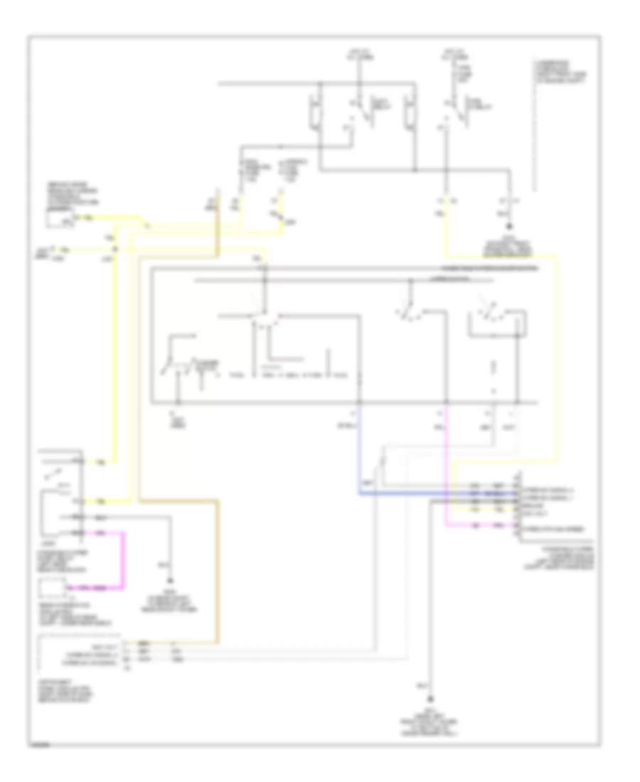
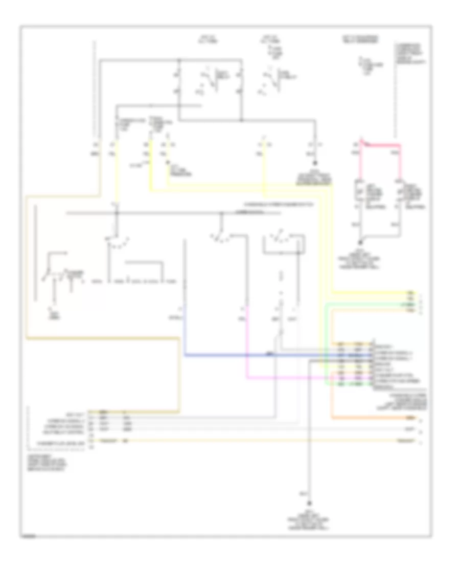
COOLING FAN
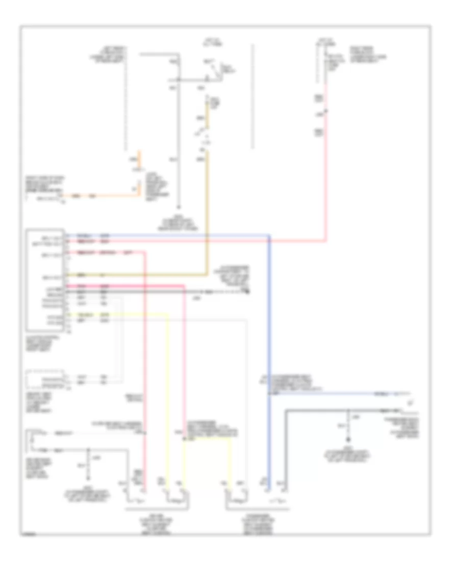
Cooling Fan Wiring Diagram for Cadillac STS V 2009
List of elements for Cooling Fan Wiring Diagram for Cadillac STS V 2009:
- (on right front frame rail, near bumper bracket) g104
- (or 476)
- 3.6l
- 3.6l & 4.6l w/o trailer provisions
- 4.4l & 4.6l
- 4.4l & 4.6l w/ trailer provisions
- 4.6l 4.4l 3.6l
- 87a
- Computer data lines system
- Ect sensor signal
- Engine control module (ecm) (3.6l: front of engine, on right valve cover) (except 3.6l: on left front frame rail, below left headlamp assembly)
- Engine coolant temperature (ect) sensor (3.6l: in center of left cylinder head) (4.4l: rear of right cylinder head) (4.6l: in rear side of right cylinder head)
- Engine cooling fan
- Engine cooling fan resistor
- Fan 1 fuse 30a
- Fan 2 fuse 30a
- G104 (on right front frame rail, near bumper bracket)
- Hi fan spd relay
- Hi spd fan rly ctrl
- Hot at all times
- Hot w/ pwr/ trn relay energized
- Left engine cooling fan (behind radiator)
- Lo fan spd relay
- Low reference
- Low spd fan rly ctrl
- Post 02 snsr fuse 15a
- Right engine cooling fan (behind radiator)
- S/p fan relay
- Serial data bus +
- Serial data bus -
- Tan
- Underhood fuse block (right front side of engine compt)
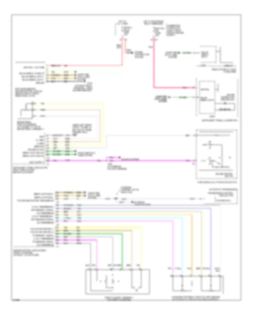
CRUISE CONTROL
3.6L VIN V
3.6L VIN V, Cruise Control Wiring Diagram for Cadillac STS V 2009
List of elements for 3.6L VIN V, Cruise Control Wiring Diagram for Cadillac STS V 2009:
- (n engine harness, 387 cm from x102)
- (near left front strut tower, at bottom of inside fender well) g101
- 5 v ref
- 5 volt reference
- 5 volt reference 1
- 5 volt reference 2
- Accelerator pedal position (app) sensor (attached to top of accelerator pedal)
- App sensor 1 signal
- App sensor 2 signal
- Automatic transmission
- Brake pedal position sensor (attached to top of brake pedal assembly)
- Ccp/rly coils fuse 10a
- Computer computer data lines data lines system system
- Computer data lines system
- Cruise control switch
- Cruise ind
- Cruise sw sig
- Display
- Distance sensing cruise control module (behind front fascia, near hood latch)
- Driver information center (dic)
- Ecm/tcm ign fuse 15a
- Engine control module (ecm) (front of engine, on right valve cover)
- Exterior lights system
- G104 (on right front frame rail, near bumper bracket)
- Gmlan serial data
- Gmlan serial data +
- Gmlan serial data -
- Gmlan serial wake up
- Gnd
- Ground
- Head up display (hud) (if equiped)
- Hot at all times
- Hot w/ run/crank relay energized
- Ignition
- Ignition 1 voltage
- Instrument panel cluster (ipc)
- Instrument panel module (ipm) (right side of dash, behind glove box)
- J147
- J225 (in steering column harness)
- Lo ref
- Logic
- Low reference
- Pnk
- Power distribution system
- Sens sig
- Serial data bus +
- Serial data bus -
- Serial data gmlan
- Sound systems
- Tac motor control-1
- Tac motor control-2
- Tan
- Tcc/crs cntl
- Tcc/cruise control release sig
- Throttle body assembly (top front of engine)
- Tp sensor 1 signal
- Tp sensor 2 signal
- Transmission control module (tcm)
- Turn signal/multi-function switch
- Underhood fuse block (right front side of engine compt)
4.4L VIN D
4.4L VIN D, Cruise Control Wiring Diagram for Cadillac STS V 2009
List of elements for 4.4L VIN D, Cruise Control Wiring Diagram for Cadillac STS V 2009:
- (4.6l: in engine harness, 24 cm from x102)
- (near left front strut tower, at bottom of inside fender well) g101
- 4.4l
- 4.6l
- 5 v ref
- 5 volt reference
- 5 volt reference 1
- 5 volt reference 2
- Accelerator pedal position (app) sensor (attached to top of accelerator pedal)
- App sensor 1 signal
- App sensor 2 signal
- Automatic transmission
- Brake pedal position sensor (attached to top of brake pedal assembly)
- Ccp/rly coils fuse 10a
- Computer data lines system
- Cruise control switch
- Cruise ind
- Cruise sw sig
- Display
- Distance sensing cruise control module (behind front fascia, near hood latch)
- Driver information center (dic)
- Ecm/tcm ign fuse 15a
- Engine control module (ecm) (on left front frame rail, below left headlamp assembly)
- Exterior lights system
- G104 (on right front frame rail, near bumper bracket)
- Gmlan serial data
- Gmlan serial data +
- Gmlan serial data -
- Gmlan serial wake up
- Gnd
- Ground
- Head up display (hud) (if equiped)
- Hot at all times
- Hot w/ run/crank relay energized
- Ignition
- Ignition 1 voltage
- Instrument panel cluster (ipc)
- Instrument panel module (ipm) (right side of dash, behind glove box)
- J147
- J225 (in steering column harness)
- Lo ref
- Logic
- Low reference
- Pnk
- Power distribution system
- Sens sig
- Serial data bus +
- Serial data bus -
- Serial data gmlan
- Sound systems
- Tac motor control-1
- Tac motor control-2
- Tan
- Tcc/crs cntl
- Tcc/cruise cntl rel sig
- Throttle body assembly (top front of engine)
- Tp sensor 1 signal
- Tp sensor 2 signal
- Transmission control module (tcm)
- Turn signal/multi-function switch
- Underhood fuse block (right front side of engine compt)
4.6L VIN A
4.6L VIN A, Cruise Control Wiring Diagram for Cadillac STS V 2009
List of elements for 4.6L VIN A, Cruise Control Wiring Diagram for Cadillac STS V 2009:
- (4.6l: in engine harness, 24 cm from x102)
- (near left front strut tower, at bottom of inside fender well) g101
- 4.4l
- 4.6l
- 5 v ref
- 5 volt reference
- 5 volt reference 1
- 5 volt reference 2
- Accelerator pedal position (app) sensor (attached to top of accelerator pedal)
- App sensor 1 signal
- App sensor 2 signal
- Automatic transmission
- Brake pedal position sensor (attached to top of brake pedal assembly)
- Ccp/rly coils fuse 10a
- Computer data lines system
- Cruise control switch
- Cruise ind
- Cruise sw sig
- Display
- Distance sensing cruise control module (behind front fascia, near hood latch)
- Driver information center (dic)
- Ecm/tcm ign fuse 15a
- Engine control module (ecm) (on left front frame rail, below left headlamp assembly)
- Exterior lights system
- G104 (on right front frame rail, near bumper bracket)
- Gmlan serial data
- Gmlan serial data +
- Gmlan serial data -
- Gmlan serial wake up
- Gnd
- Ground
- Head up display (hud) (if equiped)
- Hot at all times
- Hot w/ run/crank relay energized
- Ignition
- Ignition 1 voltage
- Instrument panel cluster (ipc)
- Instrument panel module (ipm) (right side of dash, behind glove box)
- J147
- J225 (in steering column harness)
- Lo ref
- Logic
- Low reference
- Pnk
- Power distribution system
- Sens sig
- Serial data bus +
- Serial data bus -
- Serial data gmlan
- Sound systems
- Tac motor control-1
- Tac motor control-2
- Tan
- Tcc/crs cntl
- Tcc/cruise cntl rel sig
- Throttle body assembly (top front of engine)
- Tp sensor 1 signal
- Tp sensor 2 signal
- Transmission control module (tcm)
- Turn signal/multi-function switch
- Underhood fuse block (right front side of engine compt)
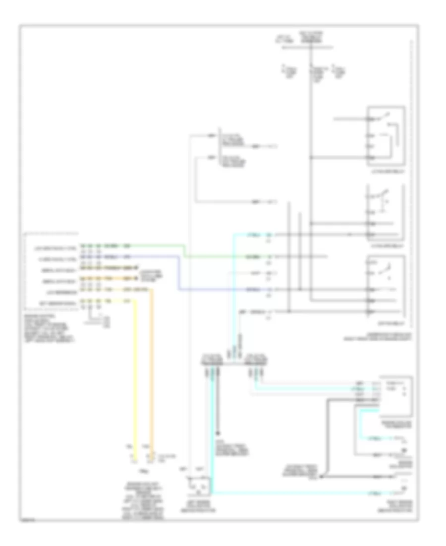
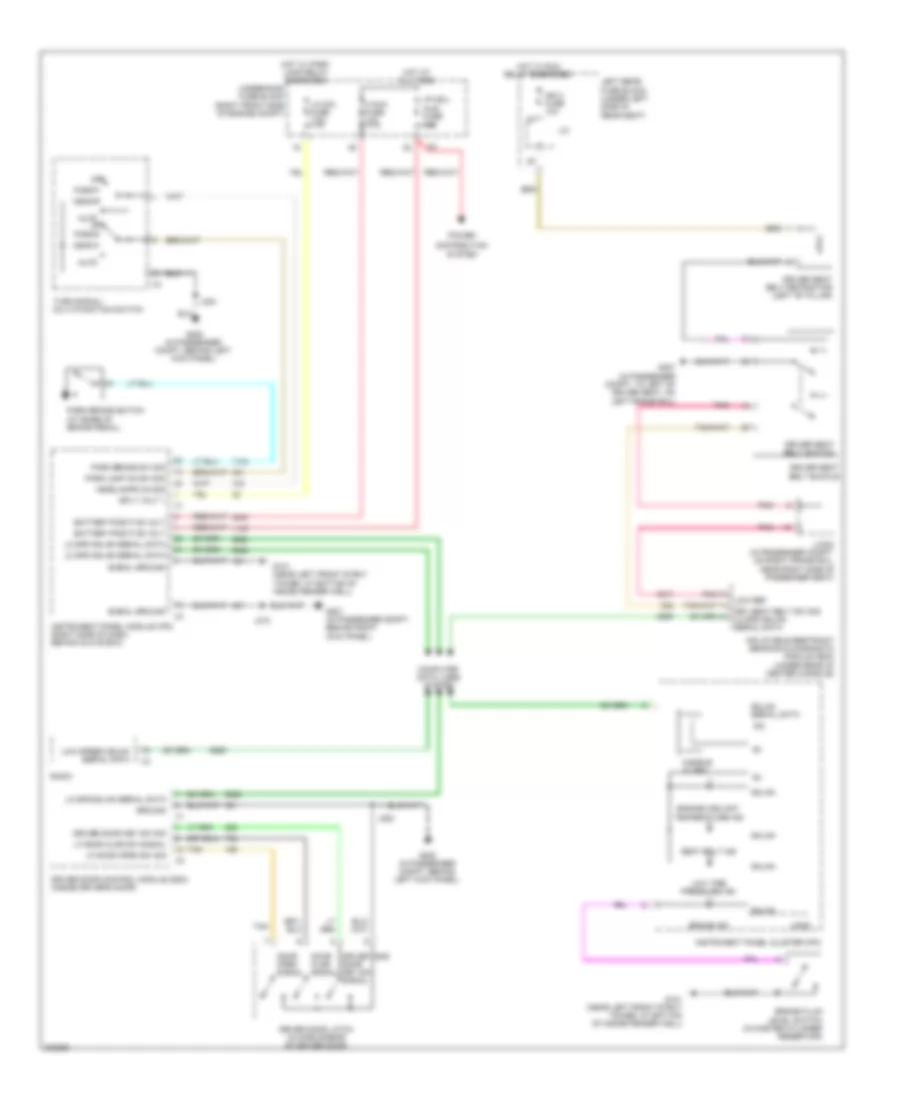
DEFOGGERS
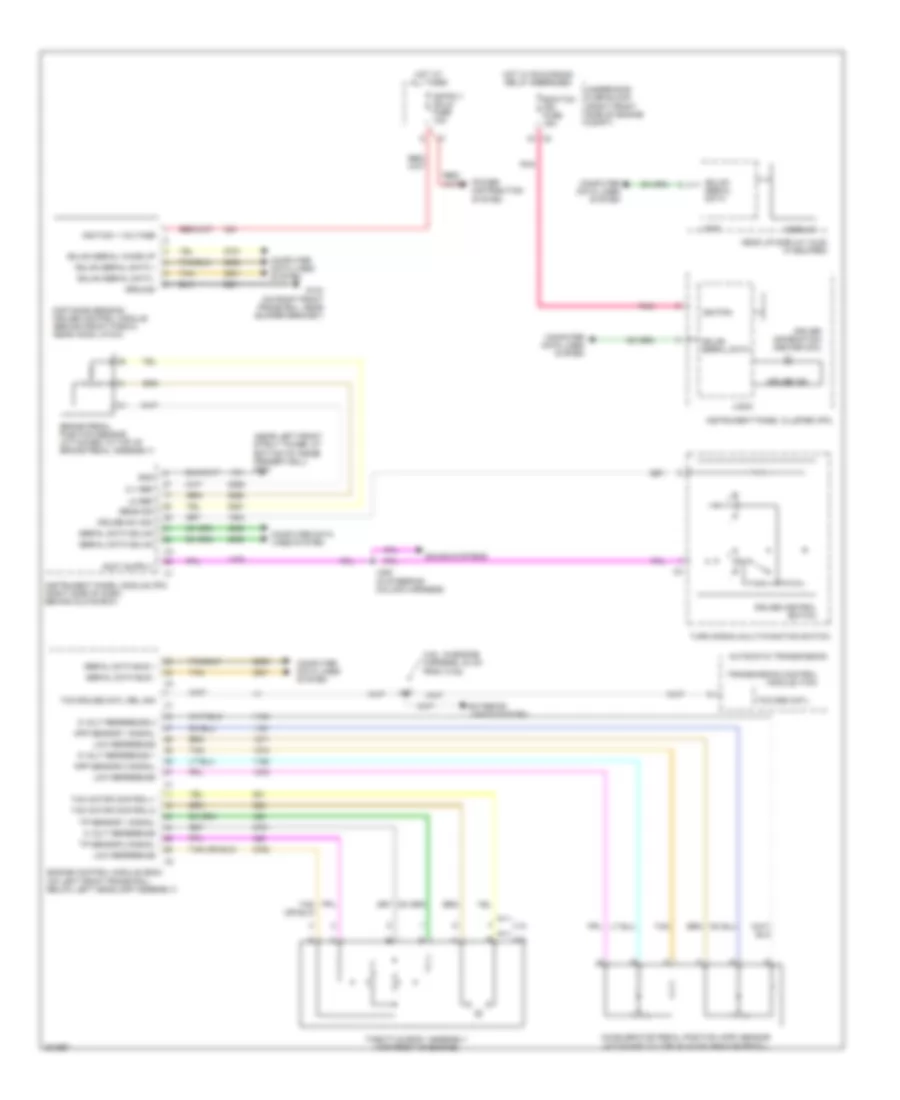
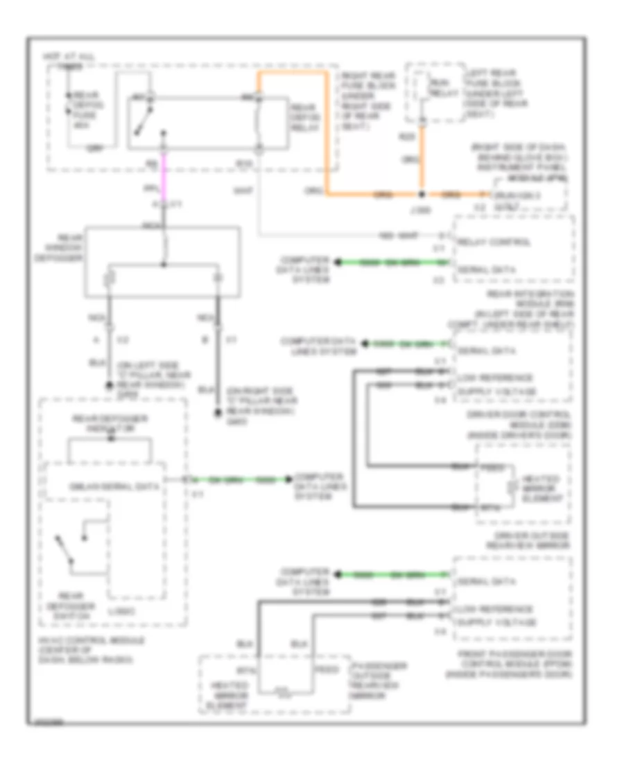
Defoggers Wiring Diagram for Cadillac STS V 2009
List of elements for Defoggers Wiring Diagram for Cadillac STS V 2009:
- (right side of dash, behind glove box) instrument panel module (ipm)
- Computer data lines system
- Driver door control module (ddm) (inside driver's door)
- Driver outside rearview mirror
- Feed
- Front passenger door control module (fpdm) (inside passenger's door)
- Gmlan serial data
- Heated mirror element
- Hot at all times
- Hvac control module (center of dash, below radio)
- J300
- Left rear fuse block (under left side of rear seat)
- Logic
- Low reference
- Nca
- Passenger outside rearview mirror
- R10
- R25
- Rear defog fuse 40a
- Rear defog relay
- Rear defogger indicator
- Rear defogger switch
- Rear integration module (rim) (in left side of rear compt, under rear shelf)
- Rear window defogger
- Relay control
- Right rear fuse block (under right side of rear seat)
- Rtn
- Run ign 3 volt
- Run relay
- Serial data
ELECTRONIC POWER STEERING
Electronic Power Steering Wiring Diagram, with Active Brake for Cadillac STS V 2009
List of elements for Electronic Power Steering Wiring Diagram, with Active Brake for Cadillac STS V 2009:
- (near left front strut tower, at bottom of inside fender well) g101
- Actr frt active sig gnd
- Actr frt active sig mtr u
- Actr frt active sig mtr w
- Actr frt active sig u
- Actr frt active sig v
- Actr frt active sig w
- Afs fuse 30a
- Batt positive volt
- Can bus high serial data
- Can bus low serial data
- Computer data lines system
- Electronic brake control module (ebcm) (right front corner of engine compt)
- G200 (in passenger compt, behind left kick panel)
- Gnd
- Hot at all times
- Hot w/ run relay energized
- Ign
- Ign 3 fuse 10a
- J/c
- Left rear fuse block (under left side of rear seat)
- Pnk
- Power steering control module (pscm) (left side of dash, above park brake pedal)
- Serial data +
- Serial data -
- Serial data wakeup
- Steering angle sensor
- Tan
- Tan/
- Underhood fuse block (right front side of engine compt)
- Upper intermediate steering shaft
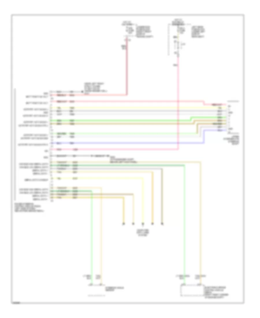
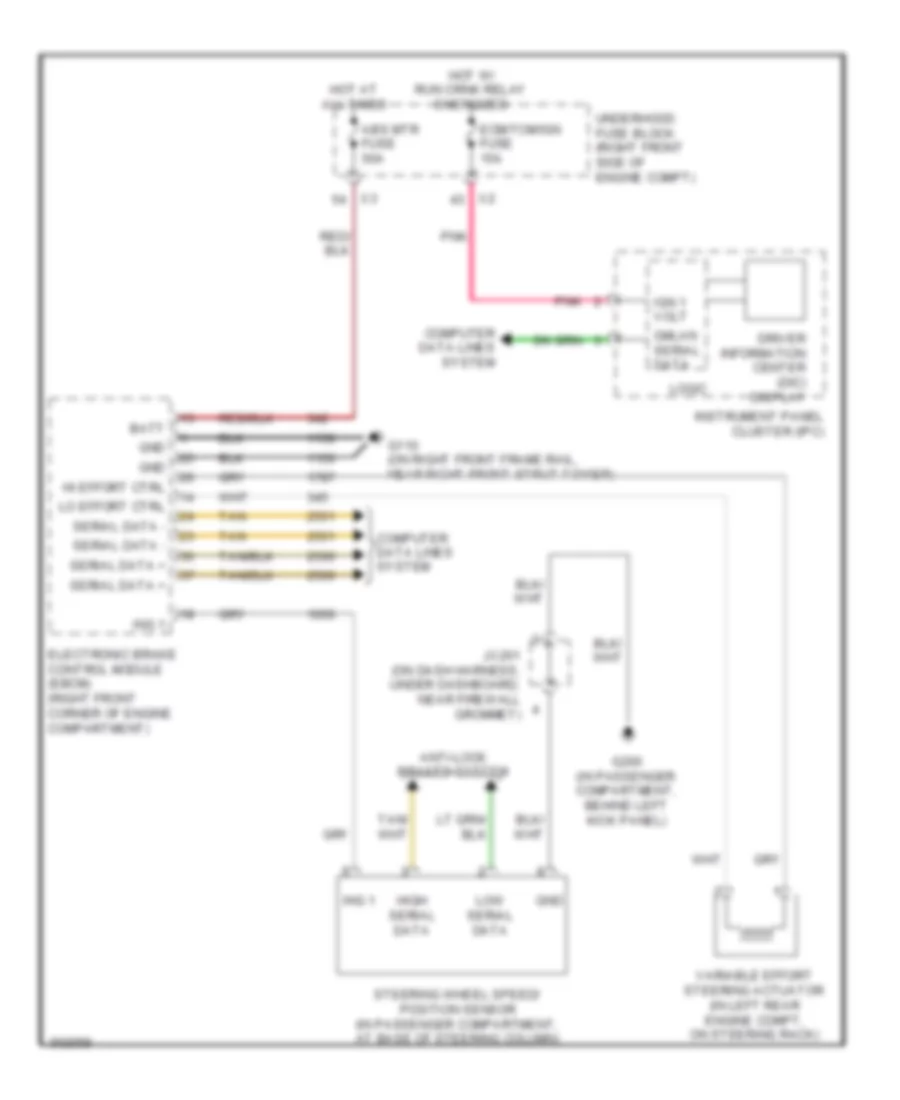
Electronic Power Steering Wiring Diagram, without Active Brake for Cadillac STS V 2009
List of elements for Electronic Power Steering Wiring Diagram, without Active Brake for Cadillac STS V 2009:
- Abs mtr fuse 50a
- Anti-lock brakes system
- Batt
- Computer data lines system
- Driver information center (dic) display
- Ecm/tcm/ign fuse 15a
- Electronic brake control module (ebcm) (right front corner of engine compartment)
- G110 (on right front frame rail, near right front strut tower)
- G200 (in passenger compartment, behind left kick panel)
- Gmlan serial data
- Gnd
- Hi effort ctrl
- High serial data
- Hot at all times
- Hot w/ run crnk relay energized
- Ign 1 volt
- Ing 1
- Instrument panel cluster (ipc)
- Jx201 (on dash harness, under dashboard, near firewall grommet)
- Lo effort ctrl
- Logic
- Low serial data
- Pnk
- Serial data +
- Serial data -
- Steering wheel speed/ position sensor (in passenger compartment, at base of steering column)
- Tan
- Underhood fuse block (right front side of engine compt)
- Variable effort steering actuator (in left rear engine compt, on steering rack)
ELECTRONIC SUSPENSION
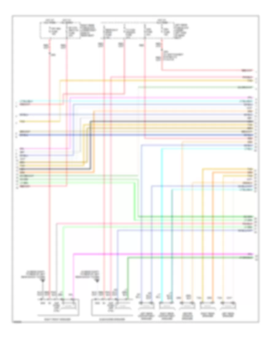
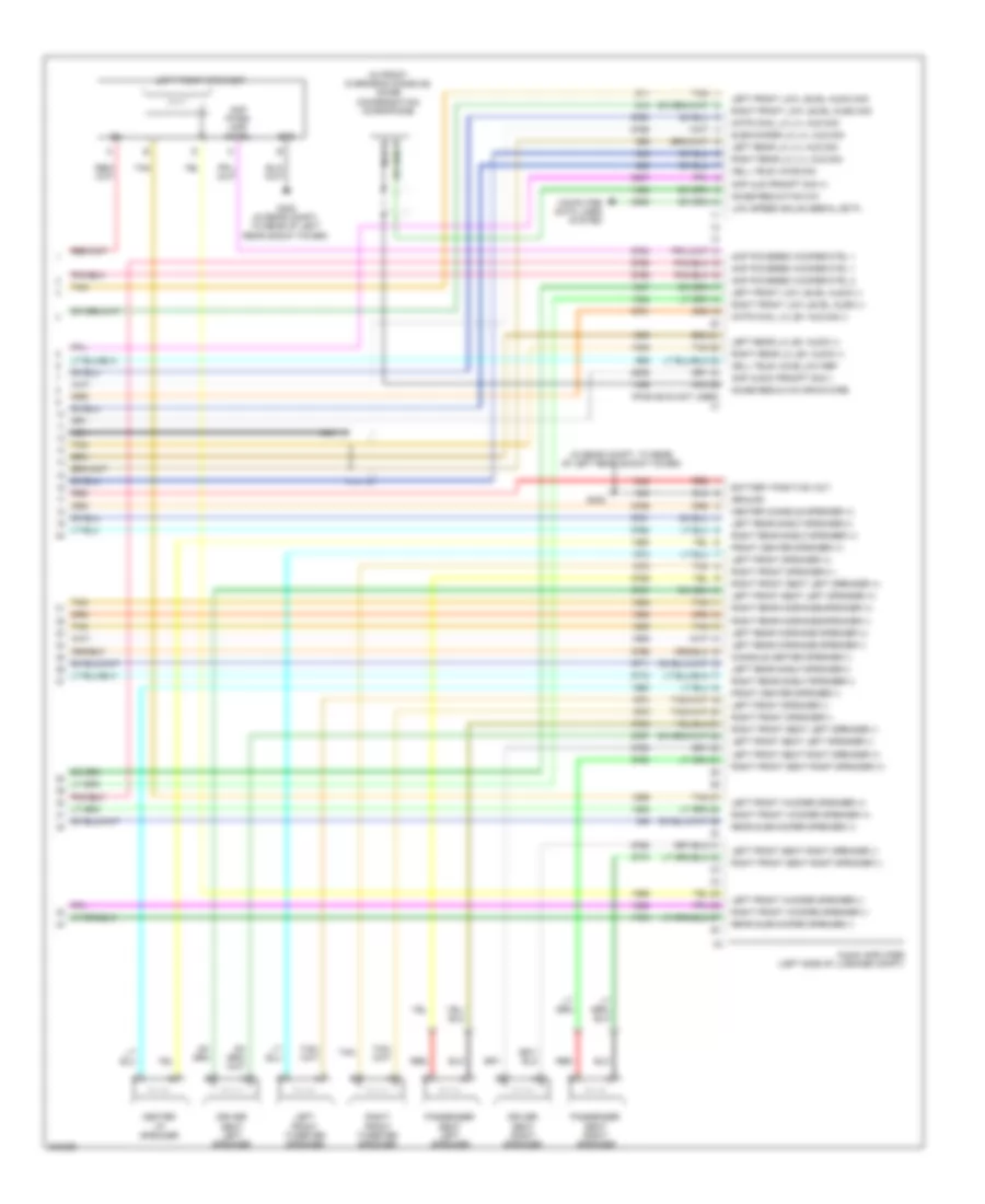
Electronic Suspension Wiring Diagram for Cadillac STS V 2009
List of elements for Electronic Suspension Wiring Diagram for Cadillac STS V 2009:
- (behind right rear tire) automatic level control (alc) compressor
- (in rear compt, to rear of right rear shock tower) g401
- Automatic level
- Batt
- Battery voltage
- Computer data lines system
- Data signal
- Driver information center (dic) display
- Ekm/i/p mdl fuse 10a
- Elc cmprsr fuse 30a
- Elc cmprsr relay
- Elc exh fuse 10a
- Elec relay ctrl
- Electronic suspension control (esc) module (below right "c" pillar)
- G401 (in rear compt, to rear of right rear shock tower)
- Gmlan ser data +
- Gmlan ser data -
- Ground
- High serial data
- Hot at all times
- Hot w/ run relay energized
- Instrument panel cluster (ipc)
- Ipc class 2
- Left front shock absorber actuator (top of left front strut tower)
- Left front suspension position sensor (near left front strut)
- Left rear fuse block (under left side of rear seat)
- Left rear shock absorber actuator (top of left rear strut tower)
- Left rear suspension position sensor (near left rear strut)
- Lf damping ctrl
- Lf damping increase
- Lf position sens
- Lf sens vol ref
- Lo serial data
- Logic
- Lr damping ctrl
- Lr position sens
- Lr sens vol ref
- Mrtd mdl fuse 25a
- Nca
- R10
- Rf damping ctrl
- Rf position sens
- Rf raid ctrl
- Rf sens vol ref
- Right front shock absorber actuator (top of right front strut tower)
- Right front suspension position sensor (near right front strut)
- Right rear shock absorber actuator (top of right rear strut tower)
- Right rear suspension position sensor (near right rear strut)
- Rr damping decrease
- Rr damping increase
- Rr position sens
- Rr sens vol ref
- Sensor low ref
- Tan
- Underhood fuse block (right front side of engine compt)
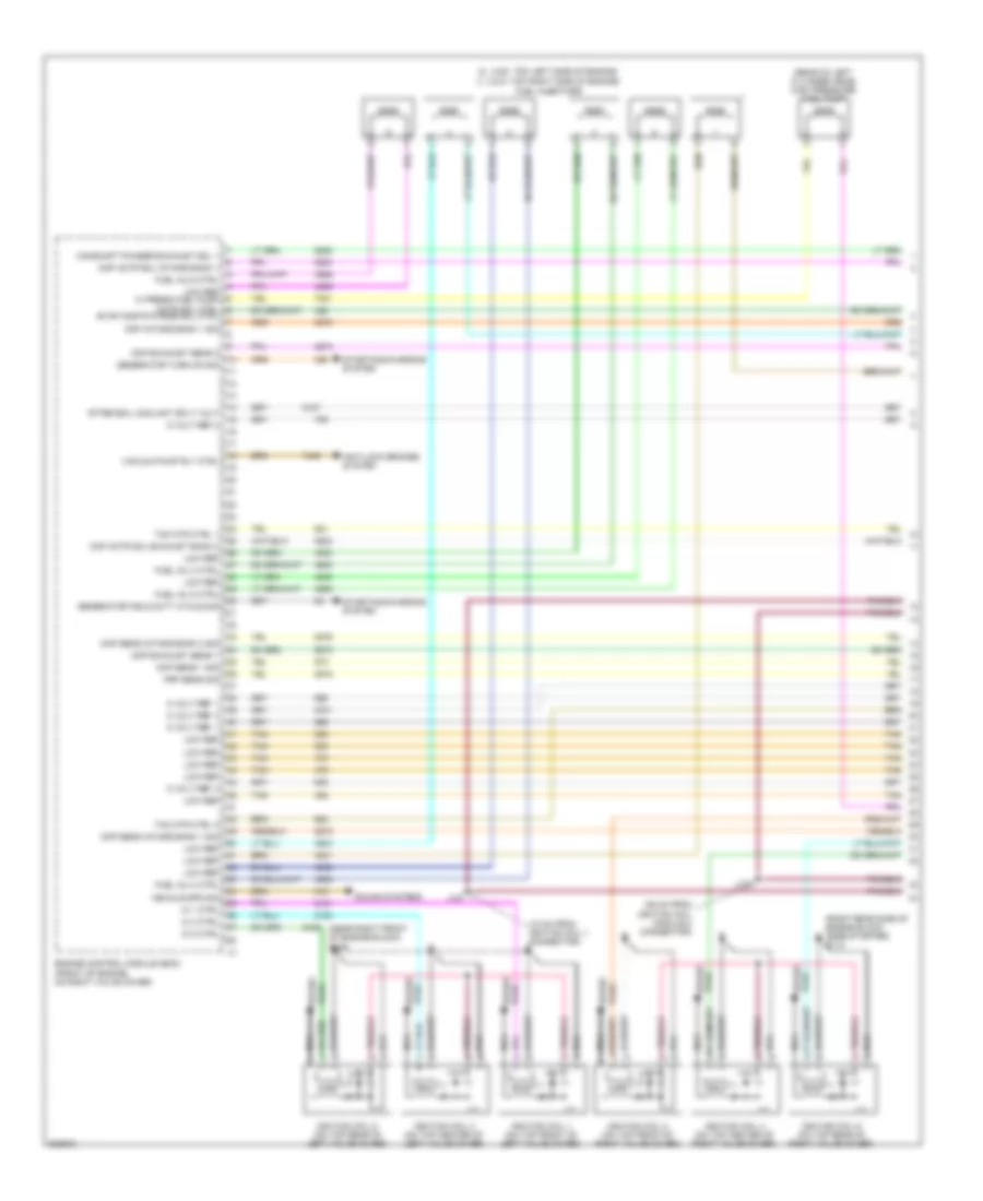
ENGINE PERFORMANCE
3.6L VIN V
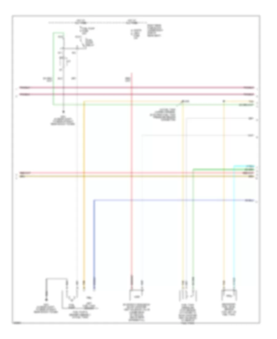
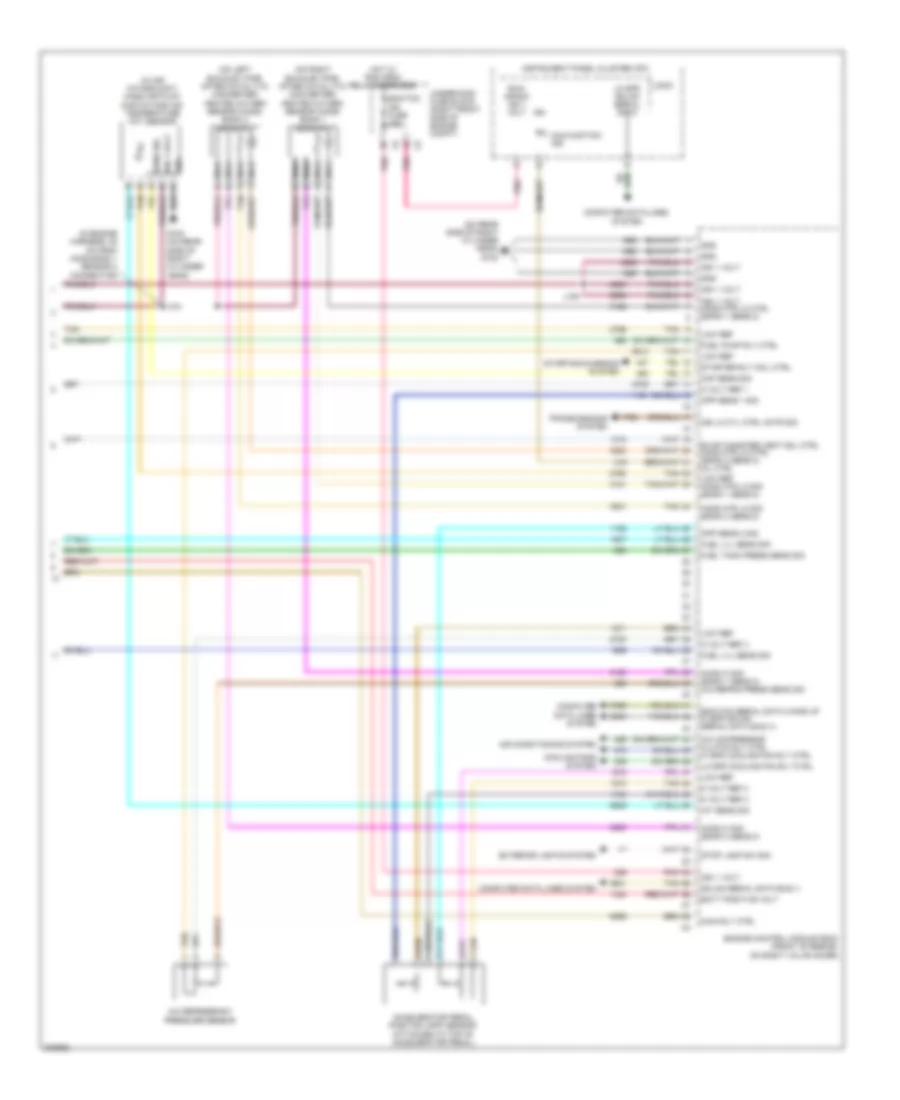
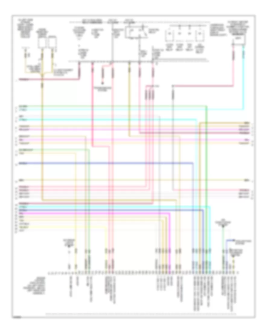
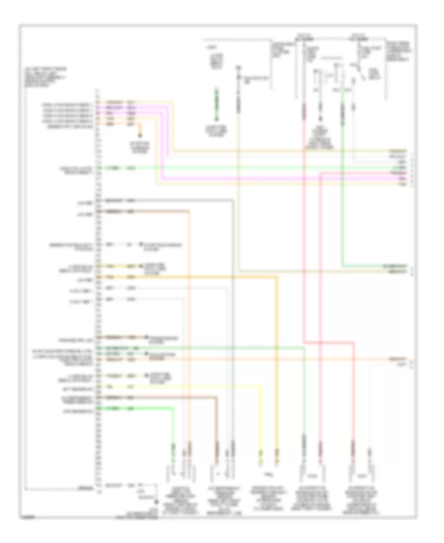
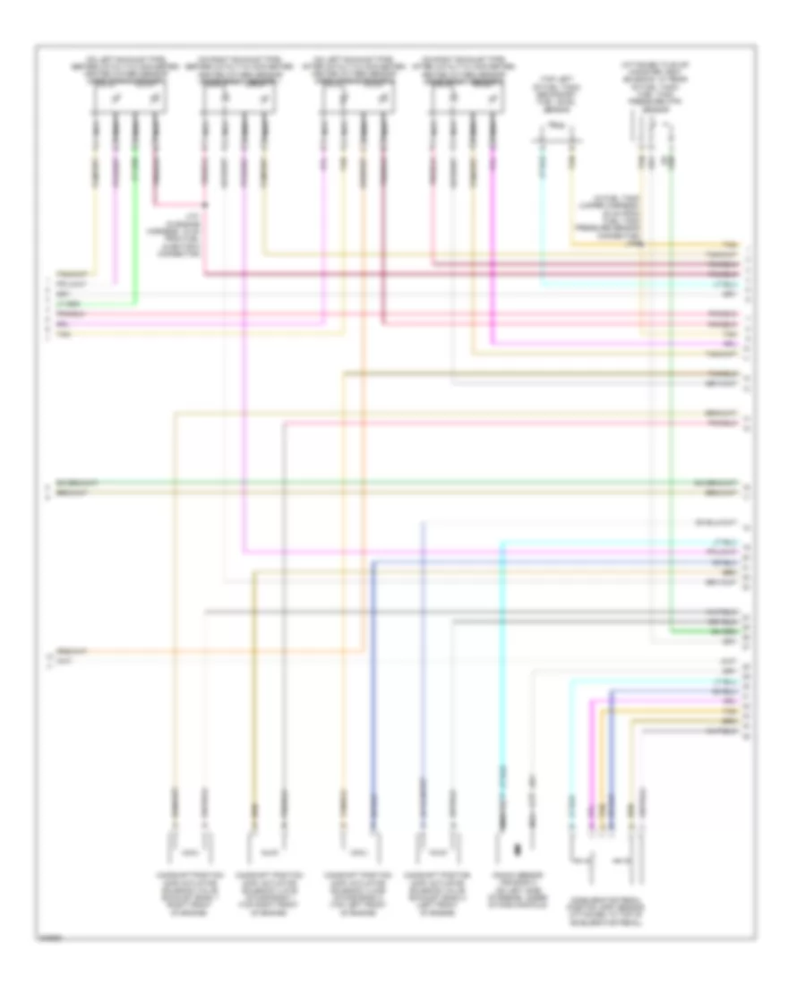
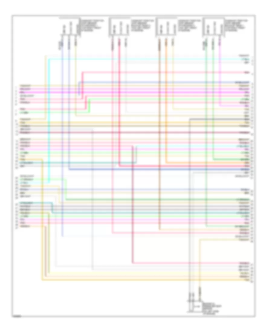
3.6L VIN V, Engine Performance Wiring Diagram (1 of 5) for Cadillac STS V 2009
List of elements for 3.6L VIN V, Engine Performance Wiring Diagram (1 of 5) for Cadillac STS V 2009:
- (1, 3 & 5: top right side of engine) fuel injectors
- (18 cm from ignition coil 1 connector)
- (2, 4 & 6: top left side of engine)
- (36 cm from ignition coil module 2 connector)
- (near right front of engine block) g109
- (rear of left cylinder head) high pressure fuel pump
- (right rear side of engine block, near starter) g112
- 5 volt ref 1
- 5 volt ref 2
- 5 volt ref 3
- After boil coolant sply volt
- Anti-lock brakes system
- Camshaft phaser exhaust sol 1
- Ckp sens 1 sig
- Cmp actr sol exhaust bank 2
- Cmp actr sol intake bank 1
- Cmp exhaust sens 1
- Cmp exhaust sens 2
- Cmp intake bank 1 sig
- Cmp sens intake bank 1 sig
- Cmp sens intake bank 2 sig
- Engine control module (ecm) (front of engine, on right valve cover)
- Evap cnstr purge sol ctrl
- Frp sens sig
- Fuel inj 2 ctrl
- Fuel inj 3 ctrl
- Fuel inj 5 ctrl
- Fuel inj 6 ctrl
- Generator field duty cycle sig
- Generator turn on sig
- Ic 1 ctrl
- Ic 3 ctrl
- Ic 5 ctrl
- Ignition coil 1 (on top front of left valve cover)
- Ignition coil 2 (on top front of right valve cover)
- Ignition coil 3 (on top center of left valve cover)
- Ignition coil 4 (on top center of right valve cover)
- Ignition coil 5 (on top rear of left valve cover)
- Ignition coil 6 (on top rear of right valve cover)
- J127
- J131
- Low ref
- Low ref hi press fuel pump actr sol ctrl
- Nca
- Plug spark
- Sound systems
- Spark plug
- Starting/charging system
- Tac mtr ctrl 1
- Tac mtr ctrl 2
- Tan
- Vacuum pump rly ctrl
- Vehicle spd sig
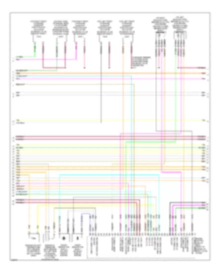
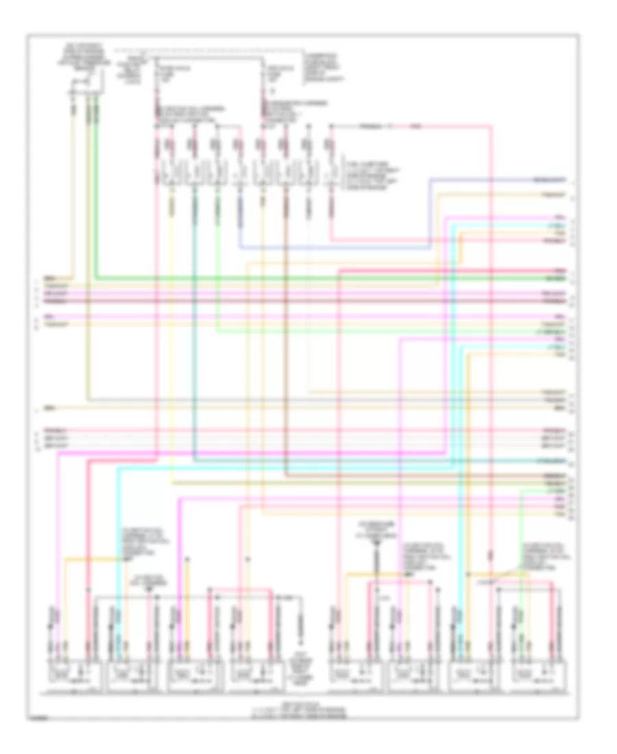
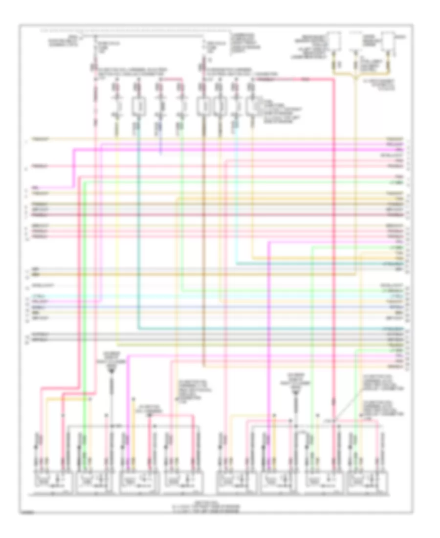
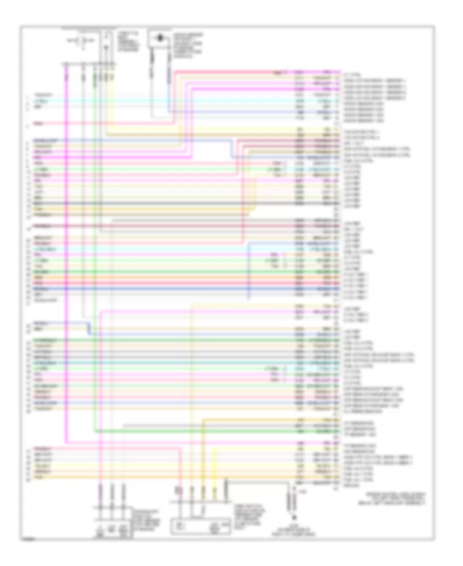
3.6L VIN V, Engine Performance Wiring Diagram (2 of 5) for Cadillac STS V 2009
List of elements for 3.6L VIN V, Engine Performance Wiring Diagram (2 of 5) for Cadillac STS V 2009:
- (bank 1 sens 1) ho2s lo sig
- (bank 1 sens 1) ho2s low ref
- (bank 2 sens 1)
- (bank 2 sens 1) ho2s ref volt
- (bank 2 sens 1) low ref
- (in engine harness, 27 cm from evap canister purge solenoid valve connector) j101
- (on left exhaust pipe, before catalytic converter) heated oxygen sensor (ho2s) bank 2 sensor 1
- (on right exhaust pipe, before catalytic converter) heated oxygen sensor (ho2s) bank 1 sensor 1
- (on right side of engine, near valve cover) evaporative emissions (evap) canister purge solenoid valve
- (top left front of engine) camshaft position (cmp) actuator solenoid valve exhaust bank 2
- (top left front of engine) camshaft position (cmp) actuator solenoid valve intake bank 2
- (top right front of engine) camshaft position (cmp) actuator solenoid valve exhaust bank 1
- (top right front of engine) camshaft position (cmp) actuator solenoid valve intake bank 1
- Ect sens sig
- Engine control module (ecm) (front of engine, on right valve cover)
- Engine coolant temperature (ect) sensor (in center of left cylinder head)
- Engine oil pressure (eop) sensor (on left side of engine, attached to oil filter adapter housing)
- Fuel inj 1 ctrl
- Fuel inj 4 ctrl
- Ho2s hi sig
- Ho2s htr lo ctrl
- Ic 2 ctrl
- Ic 4 ctrl
- Ic 6 ctrl
- Ign 1 volt
- Knock sens 1 sig
- Knock sens 2 sig
- Knock sensor (ks) bank 1 (on right side of engine)
- Knock sensor (ks) bank 2 (on left side of engine)
- Low ref
- Nca
- Oil press sens sig
- Tan
- Tp sens 1 sig
- Tp sens 2 sig
- X1 (bank 1 sens 1) ho2s htr lo ctrl
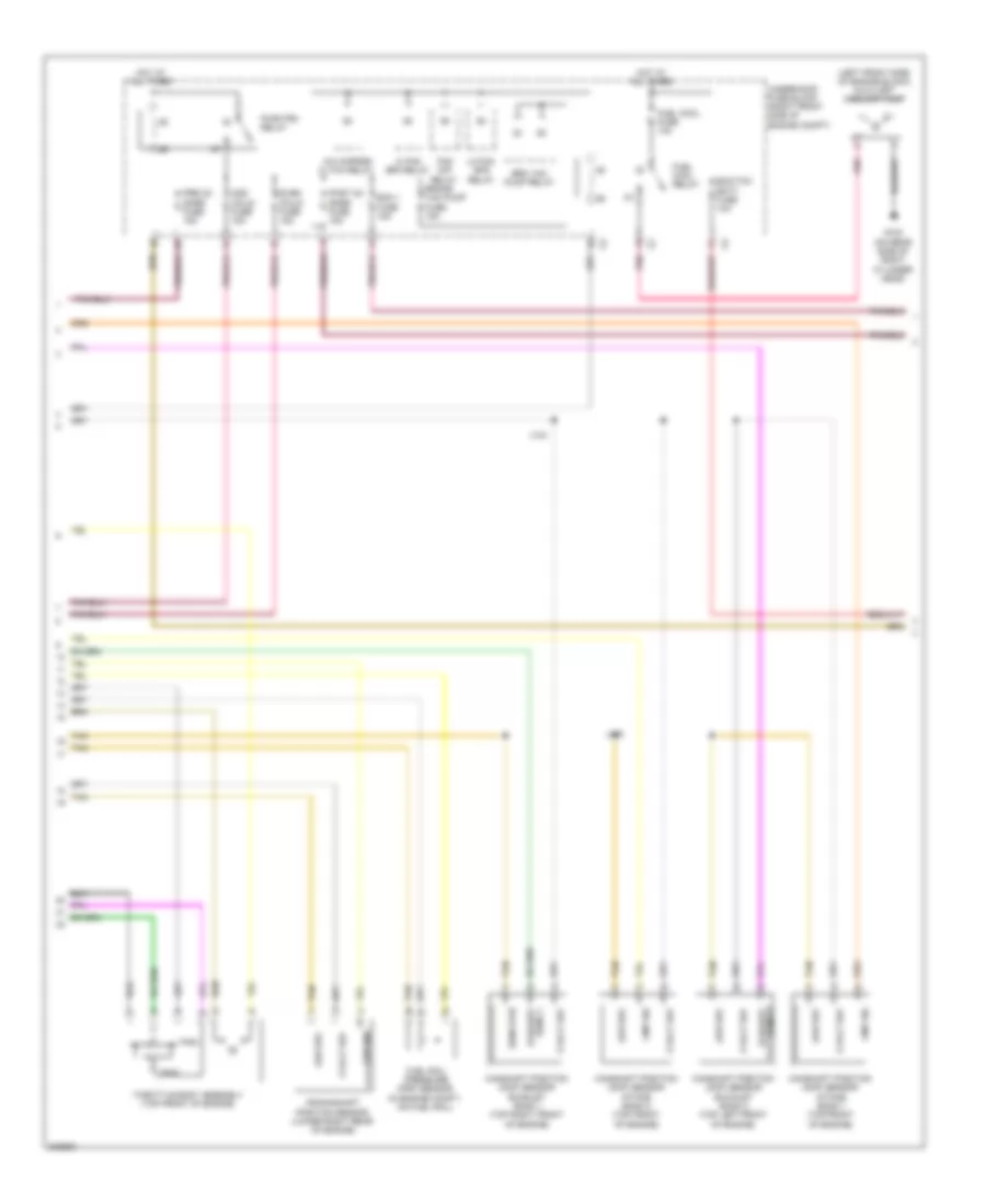
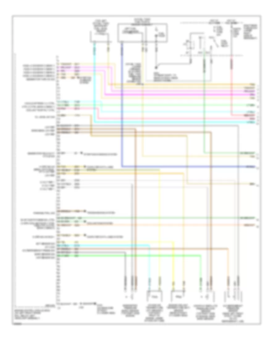
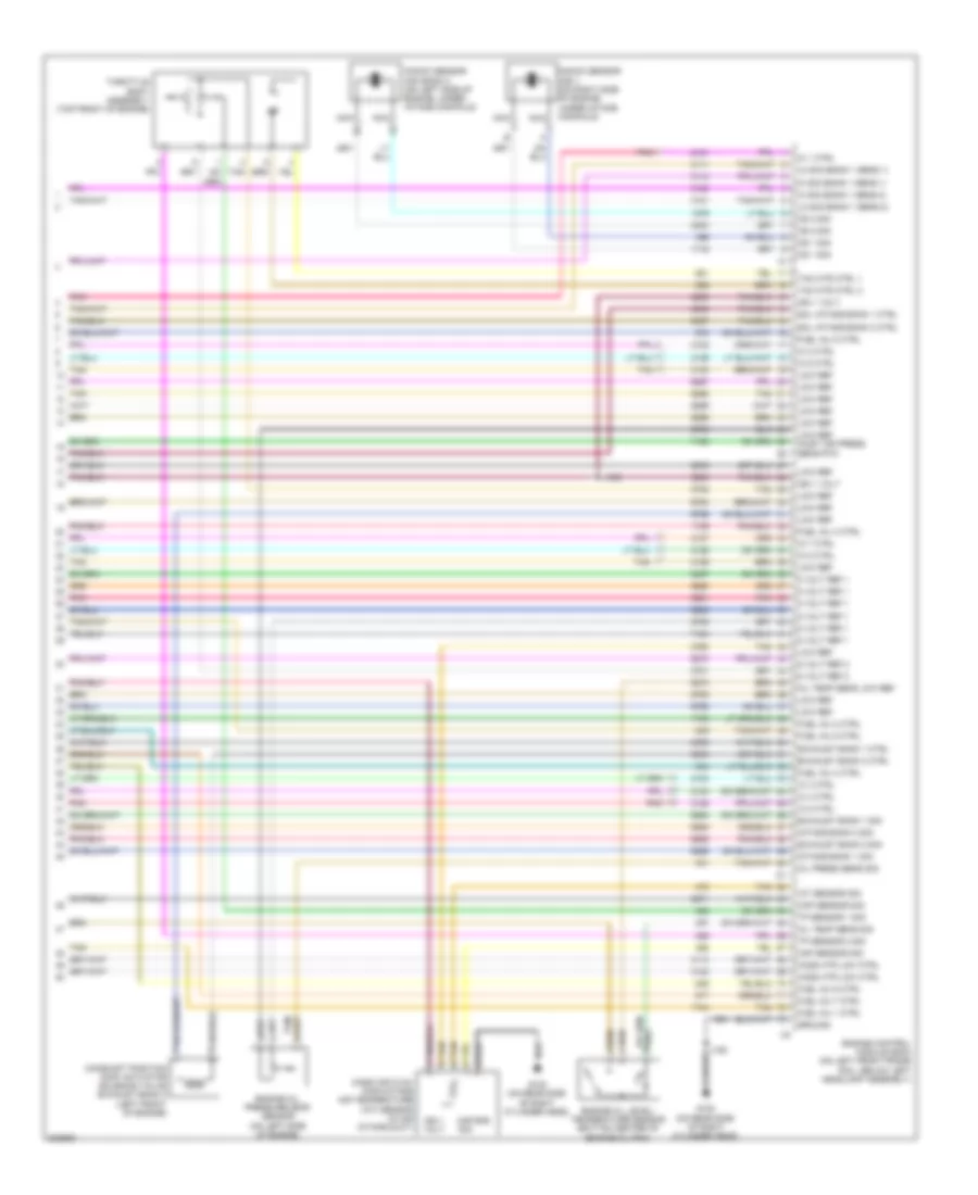
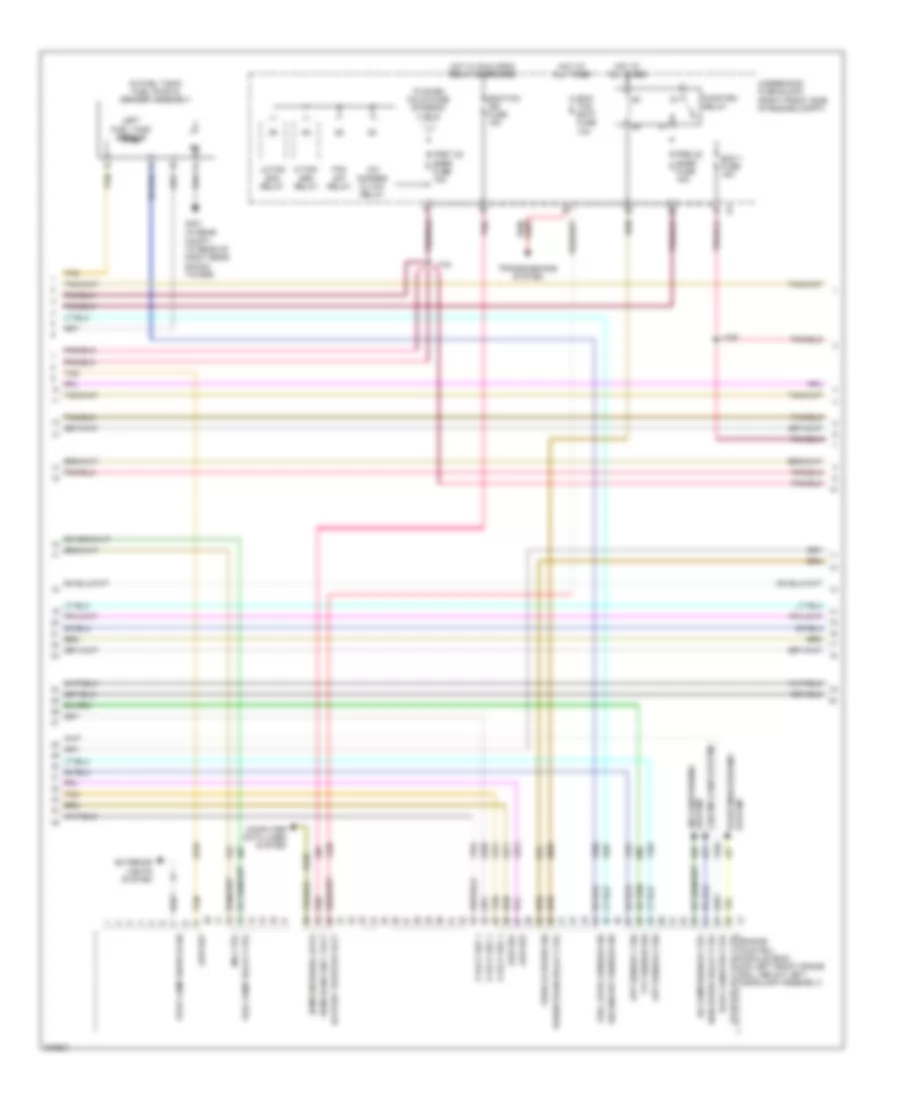
3.6L VIN V, Engine Performance Wiring Diagram (3 of 5) for Cadillac STS V 2009
List of elements for 3.6L VIN V, Engine Performance Wiring Diagram (3 of 5) for Cadillac STS V 2009:
- (in engine compt, on fuel rail)
- (left front side of engine block) auxiliary coolant pump
- 5 volt ref
- A/c cmprsr cltch relay
- Brake vac pump fuse 15a
- Brk vac pump relay
- Camshaft position (cmp) sensor exhaust bank 1 (top right front of engine)
- Camshaft position (cmp) sensor exhaust bank 2 (top left front of engine)
- Camshaft position (cmp) sensor intake bank 1 (top front of engine)
- Camshaft position (cmp) sensor intake bank 2 (top front of engine)
- Ckp sig
- Cmp sig
- Crankshaft position sensor (lower right rear of engine)
- Ecm 1 fuse 15a
- Ecm/tcm batt fuse 10a
- Even coils fuse 15a
- Fan s/p relay
- Fuel cool fuse 10a
- Fuel cool relay
- Fuel rail pressure (frp) sensor
- G100 (on rear side of right cylinder head)
- Hi fan spd relay
- Hot at all times
- J124
- J160
- Lo fan spd relay
- Low ref
- Odd coils fuse 15a
- Pnk
- Post o2 snsr fuse 15a
- Pre o2 snsr fuse 15a
- Pwr/trn relay
- Sens 1 exhaust
- Sens 2 exhaust
- Sens rtn
- Tan
- Throttle body assembly (top front of engine)
- Tps1
- Tps2
- Underhood fuse block (right front side of engine compt)
3.6L VIN V, Engine Performance Wiring Diagram (4 of 5) for Cadillac STS V 2009
List of elements for 3.6L VIN V, Engine Performance Wiring Diagram (4 of 5) for Cadillac STS V 2009:
- (in fuel tank jumper harness, 28 cm from fuel tank pressure sensor connector)
- Cnstr vent fuse 10a
- Evaporative emission (evap) canister vent solenoid valve (under rear of vehicle, above rear differential)
- Fuel pump
- Fuel pump & sender assembly (in fuel tank)
- Fuel pump fuse 20a
- Fuel pump relay
- Fuel tank pressure (ftp) sensor (attached to evap canister vent solenoid, at rear of fuel tank)
- G401 (in rear compt, to rear of right rear shock tower)
- Hot at all times
- J/c
- J406
- Left fuel tank sensor
- R11
- R12
- R13
- R15
- Right rear fuse block (under right side of rear seat)
- Secondary fuel level sensor (top left of fuel tank)
- Tan
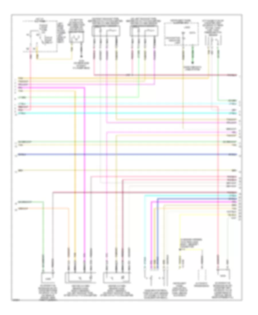
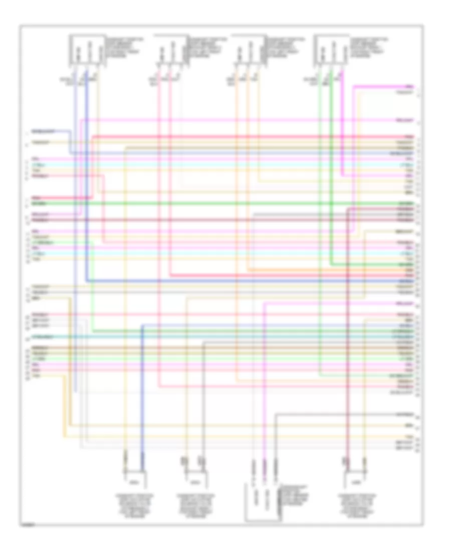
3.6L VIN V, Engine Performance Wiring Diagram (5 of 5) for Cadillac STS V 2009
List of elements for 3.6L VIN V, Engine Performance Wiring Diagram (5 of 5) for Cadillac STS V 2009:
- (in air intake duct) mass air flow (maf)/intake air temperature (iat) sensor
- (in engine harness, 52 cm from ho2s bank 1 sensor 2 connector)
- (on left exhaust pipe, after catalytic converter) heated oxygen sensor (ho2s) bank 2 sensor 2
- (on rear side of right cylinder head) g100
- (on right exhaust pipe, after catalytic converter) heated oxygen sensor (ho2s) bank 1 sensor 2
- 5 volt ref 1
- 5 volt ref 2
- 5 volt ref 3
- A/c compressor clutch rly ctrl hi spd cooling fan rly ctrl
- A/c refrigerant pressure sensor
- Accelerator pedal position (app) sensor (attached to top of accelerator pedal)
- Air conditioning system
- App sens 1 sig
- App sens 2 sig
- Batt positive volt
- Computer data lines system
- Cooling fans system
- Ecm/tcm ign fuse 15a
- Ecm/tcm serial data wake up hi spd gmlan serial data bus (+)
- Engine control module (ecm) (front of engine, on right valve cover)
- Evap canister vent sol ctrl ho2s htr lo ctrl (bank 2 sens 2) mil ctrl
- Exterior lights system
- Fuel lvl sens sig
- Fuel pump rly ctrl
- Fuel tank press sens sig
- G100 (on rear side of right cylinder head)
- Gmlan serial data bus (-)
- Gnd
- Ho2s hi sig (bank 1 sens 2) a/c refrig press sens sig
- Ho2s hi sig (bank 2 sens 2)
- Ho2s htr lo sig (bank 2 sens 2)
- Hot w/ run crnk relay energized
- Iat sens sig
- Ign
- Ign 1 volt
- Ign 1 volt ho2s htr lo ctrl (bank 1 sens 2)
- Ign lk cyl ctrl actr sig
- Instrument panel cluster (ipc)
- J104
- J109
- Lo spd cooling fan rly ctrl
- Lo spd gmlan serial data
- Logic
- Low ref
- Low ref ho2s htr lo sig (bank 1 sens 2)
- Maf sens sig
- Main rly ctrl
- Malfunction ind
- Nca
- Pnk
- Run/ crank ign 1 volt
- Sens sig
- Starter rly coil ctrl
- Starting/charging system
- Stop lamp sw sig
- Tan
- Tan c
- Transmissions system
- Underhood fuse block (right front side of engine compt)
4.4L VIN D
4.4L VIN D, Engine Performance Wiring Diagram (1 of 6) for Cadillac STS V 2009
List of elements for 4.4L VIN D, Engine Performance Wiring Diagram (1 of 6) for Cadillac STS V 2009:
- (in fuel tank jumper harness, 28 cm from fuel tank pressure sensor connector) j406
- (in fuel tank) fuel pump & sender assembly
- (top left of fuel tank) secondary fuel level sensor
- 5 volt ref
- 5 volt ref 1
- A/c refrigerant press sig
- A/c refrigerant pressure sensor (near left front strut tower, on a/c refrigerant line)
- Baro sens low ref
- Baro sensor sig
- Barometric pressure (baro) sensor (top right side engine)
- Cnstr vent fuse 10a
- Computer data lines system
- Coolant pump rly ctrl
- Cooling fans system
- Ect sensor sig
- Engine control module (ecm) (on left front frame rail, below left headlamp assembly)
- Engine coolant temperature (ect) sensor (rear of right cylinder head)
- Evap cnstr purge sol ctrl
- Fuel pump
- Fuel pump fuse 20a
- Fuel pump relay
- G100 (on rear side of right cylinder head)
- G401 (in rear compt, to rear of right rear shock tower)
- Generator field duty cycle sig
- Generator turn on sig
- Ground
- Hi spd gmlan bus +
- Hi spd gmlan serial data bus -
- Ho2s hi sig (bank 2 sens 1)
- Ho2s hi sig (bank 2 sens 2)
- Ho2s lo sig (bank 2 sens 1)
- Ho2s lo sig (bank 2 sens 2)
- Hot at all times
- Htr lo ctrl (bank 2 sens 1)
- Iat 2 low ref
- Iat 2 sig
- Intake air temperature (iat) sensor 2 (top right front of engine, under intake air tube)
- J/c
- J152
- Left fuel tank sensor
- Lo spd cooling fan rly ctrl ho2s htr lo ctrl (bank 2 sens 2)
- Low ref
- Manifold absolute pressure (map) sensor (top right side of engine, near baro sensor)
- Map sensor sig
- Oil level sw sig
- Park/neutral sig
- Pnk
- R11
- R12
- R13
- R15
- Right rear fuse block (under right side of rear seat)
- Starting/ charging system
- Starting/charging system
- Tan
- Transmissions system
- Vacuum bypass vlv ctrl
4.4L VIN D, Engine Performance Wiring Diagram (2 of 6) for Cadillac STS V 2009
List of elements for 4.4L VIN D, Engine Performance Wiring Diagram (2 of 6) for Cadillac STS V 2009:
- (at bottom of radiator, between fans) charge air cooler (cac) coolant pump
- (attached to evap canister vent solenoid, at rear of fuel tank) fuel tank pressure (ftp) sensor
- (in engine harness, 19 cm from ho2s bank 1 sensor 1 connector) j113
- (on left exhaust pipe, before catalytic converter) heated oxygen sensor (ho2s) bank 2 sensor 1
- (on right exhaust pipe, before catalytic converter) heated oxygen sensor (ho2s) bank 1 sensor 1
- Accelerator pedal position (app) sensor (attached to top of accelerator pedal)
- Automatic transmission
- Computer data lines system
- Data
- Evaporative emissions (evap) canister purge solenoid valve (on rear of engine, near throttle body)
- Evaporative emissions (evap) canister vent solenoid valve (under rear of vehicle, above rear differential)
- G100 (on rear side of right cylinder head)
- Heated oxygen sensor (ho2s) bank 1 sensor 2 (on right exhaust pipe, after catalytic converter)
- Heated oxygen sensor (ho2s) bank 2 sensor 2 (on left exhaust pipe, after catalytic converter)
- Hot at all times
- Ign
- Inclr pump fuse 10a
- Inclr pump relay
- Instrument panel cluster (ipc)
- Instrument panel module (ipm) (right side of dash, behind glove box)
- J101
- Left rear fuse block (under left side of rear seat)
- Logic
- Malfunction indicator lamp
- Nca
- Pnk
- Tan
4.4L VIN D, Engine Performance Wiring Diagram (3 of 6) for Cadillac STS V 2009
List of elements for 4.4L VIN D, Engine Performance Wiring Diagram (3 of 6) for Cadillac STS V 2009:
- (in front center of engine,at number 2 injector) supercharger bypass valve solenoid
- (in left side of rear compt, under rear shelf) rear object sensor control module
- 5 volt ref 1
- A/c cmprsr cltch relay
- A/c compressor
- Air conditioning system
- App sensor 1 sig
- App sensor 2 sig
- Battery positive volt
- Clutch rly ctrl
- Cooling fans system
- Data wake up ecm/tcm serial
- Ecm 1 fuse 15a
- Ecm/tcm batt fuse 10a
- Ecm/tcm ign fuse 15a
- Engine control module (ecm) (on left front frame rail, below left headlamp assembly)
- Evap canister vent sol ctrl
- Exterior lights system
- Fan s/p relay
- Fuel pump relay ctrl
- Fuel tank press sens sig
- Hi fan spd relay
- Hi spd cooling fan rly ctrl
- Hot at all times
- Hot w/ run crnk relay energized
- Inlet air press sens sig
- Inside rearview mirror (isrvm)
- J104
- Lo fan spd relay
- Low ref
- Mil ctrl
- Pnk
- Post o2 snsr fuse 15a
- Powertrain rly ctrl
- Pre o2 snsr fuse 15a
- Pwr/trn relay
- Radio
- Run/crank ign 1 volt
- Secondary fuel lvl sens sig
- Starter rly coil ctrl
- Starting/ charging system
- Stop lamp sw sig
- Tan
- To even coils fuse (diagram 4 of 6)
- Transmissions system
- Underhood fuse block (right front side of engine compt)
- Vehicle speed sig
- W/ infotainment system 012, 014 & 015
- W/ intelligent high beam control
4.4L VIN D, Engine Performance Wiring Diagram (4 of 6) for Cadillac STS V 2009
List of elements for 4.4L VIN D, Engine Performance Wiring Diagram (4 of 6) for Cadillac STS V 2009:
- (in ignition coil harness) j137
- (in ignition coil harness, 30 cm from ignition coil module 1 connector)
- (in ignition coil harness, 30 cm from ignition coil module 7 connector) j146
- (in ignition coil harness, 31 cm from ignition coil module 8 connector) j135
- (in ignition coil harness, 36 cm from ignition module 2 connector) j131
- (on rear side of right cylinder head) g107
- (on top right side of engine) supercharger air inlet pressure sensor
- Even coils fuse 15a
- From a pwr/trn relay (diagram 3 of 6)
- Fuel injectors (1, 3, 5 & 7: top right side of engine) (2, 4, 6 & 8: top left side of engine)
- G107 (on rear side of right cylinder head)
- Ignition coils (1, 3, 5 & 7: top left side of engine) (2, 4, 6 & 8: top right side of engine)
- J127
- J133
- J142
- J144
- Nca
- Odd coils fuse 15a
- Pnk
- Pnk a
- Pnk b
- Spark plug
- Tan
- Tan c
- Underhood fuse block (right front side of engine compt)
4.4L VIN D, Engine Performance Wiring Diagram (5 of 6) for Cadillac STS V 2009
List of elements for 4.4L VIN D, Engine Performance Wiring Diagram (5 of 6) for Cadillac STS V 2009:
- 5 volt ref
- Camshaft position (cmp) actuator solenoid valve exhaust bank 1 (top right front of engine)
- Camshaft position (cmp) actuator solenoid valve intake bank 1 (top right front of engine)
- Camshaft position (cmp) actuator solenoid valve intake bank 2 (top left front of engine)
- Camshaft position (cmp) sensor exhaust bank 1 (top right front of engine)
- Camshaft position (cmp) sensor exhaust bank 2 (top left front of engine)
- Camshaft position (cmp) sensor intake bank 1 (top right front of engine)
- Camshaft position (cmp) sensor intake bank 2 (top left front of engine)
- Ckp sens sig
- Cmp sig
- Crankshaft position (ckp) sensor (top center of engine)
- Low ref
- Pnk
- Tan
4.4L VIN D, Engine Performance Wiring Diagram (6 of 6) for Cadillac STS V 2009
List of elements for 4.4L VIN D, Engine Performance Wiring Diagram (6 of 6) for Cadillac STS V 2009:
- 5 volt ref 1
- 5 volt ref 2
- Camshaft position (cmp) actuator solenoid valve exhaust bank 2 (left front of engine)
- Ckp sensor sig
- Engine control module (ecm) (on left front frame rail, below left headlamp assembly)
- Engine oil level/ temperature sensor (bottom center of engine oil pan)
- Engine oil pressure (eop) sensor (on left side of engine)
- Exhaust bank 1 ctrl
- Exhaust bank 1 sig
- Exhaust bank 2 ctrl
- Exhaust bank 2 sig
- Fuel inj 1 ctrl
- Fuel inj 2 ctrl
- Fuel inj 3 ctrl
- Fuel inj 4 ctrl
- Fuel inj 5 ctrl
- Fuel inj 6 ctrl
- Fuel inj 7 ctrl
- Fuel inj 8 ctrl
- G100 (on rear side of right cylinder head)
- Gnd
- Ground
- Hi sig (bank 1 sens 1)
- Hi sig (bank 1 sens 2)
- Ho2s htr low ctrl
- Iat sensor sig
- Ic 1 ctrl
- Ic 2 ctrl
- Ic 3 ctrl
- Ic 4 ctrl
- Ic 5 ctrl
- Ic 6 ctrl
- Ic 7 ctrl
- Ic 8 ctrl
- Ign 1 volt
- Intake bank 1 sig
- Intake bank 2 sig
- J109
- J152
- Knock sensor (ks) 1 (on right side of engine, under intake manifold)
- Knock sensor (ks) bank 2 (on left side of engine, under intake manifold)
- Ks 1 sig
- Ks 2 sig
- Lo sig (bank 1 sens 1)
- Lo sig (bank 1 sens 2)
- Low ref
- Low ref inlet air press sens rtn
- Maf sensor sig
- Maf sig
- Mass air flow (maf)/intake air temperature (iat) sensor (in air intake duct)
- Nca
- Oil press sens sig
- Oil temp sens low ref
- Oil temp sens sig
- Pnk
- Sol intake bank 1 ctrl
- Sol intake bank 2 ctrl
- Tac mtr ctrl 1
- Tac mtr ctrl 2
- Tan
- Tan d
- Tan e
- Throttle body assembly (top front of engine)
- Tp sensor 1 sig
- Tp sensor 2 sig
4.6L VIN A
4.6L VIN A, Engine Performance Wiring Diagram (1 of 6) for Cadillac STS V 2009
List of elements for 4.6L VIN A, Engine Performance Wiring Diagram (1 of 6) for Cadillac STS V 2009:
- (on left front frame rail, below left headlamp assembly) engine control module (ecm)
- 5 volt ref 1
- A/c refrigerant press sens sig
- A/c refrigerant pressure sensor (near left front strut tower, on a/c refrigerant line)
- Cnstr vent fuse 10a
- Computer data lines system
- Cooling fans system
- Ect sensor sig
- Engine coolant temperature (ect) sensor (in rear side of right cylinder head)
- Evap canister purge sol ctrl
- Evaporative emissions (evap) canister purge solenoid valve (on rear of engine, near throttle body)
- Evaporative emissions (evap) canister vent solenoid (under rear of vehicle, above rear differential)
- Fuel pump fuse 20a
- Fuel pump relay
- G100 (on rear side of right cylinder head)
- G401 (in rear compt, to rear of right rear shock tower)
- Generator field duty cycle sig
- Generator turn on sig
- Ground
- Hi spd gmlan serial data bus +
- Hi spd gmlan serial data bus -
- Ho2s hi sig (bank 2 sens 1)
- Ho2s hi sig (bank 2 sens 2)
- Ho2s htr lo ctrl (bank 2 sens 1)
- Ho2s lo sig (bank 2 sens 1)
- Ho2s lo sig (bank 2 sens 2)
- Hot at all times
- Ign
- Instrument panel cluster (ipc)
- J/c
- J152
- Lo spd cooling fan relay ctrl ho2s htr lo ctrl (bank 2 sens 2)
- Lo spd gmlan serial data
- Logic
- Low ref
- Malfunction ind
- Manifold absolute pressure (map) sensor (front center of engine, in back of throttle body)
- Map sensor sig
- Park/neutral sig
- R11
- R12
- R13
- R15
- Right rear fuse block (under right side of rear seat)
- Starting/ charging system
- Starting/charging system
- Tan
- Transmissions system
4.6L VIN A, Engine Performance Wiring Diagram (2 of 6) for Cadillac STS V 2009
List of elements for 4.6L VIN A, Engine Performance Wiring Diagram (2 of 6) for Cadillac STS V 2009:
- (attached to evap canister vent solenoid, at rear of fuel tank) fuel tank pressure (ftp) sensor
- (in fuel tank jumper harness, 28 cm from fuel tank pressure sensor connector) j406
- (on left exhaust pipe, after catalytic converter) heated oxygen sensor (ho2s) bank 2 sensor 2
- (on left exhaust pipe, before catalytic converter) heated oxygen sensor (ho2s) bank 2 sensor 1
- (on right exhaust pipe, after catalytic converter) heated oxygen sensor (ho2s) bank 1 sensor 2
- (on right exhaust pipe, before catalytic converter) heated oxygen sensor (ho2s) bank 1 sensor 1
- (top left of fuel tank) secondary fuel level sensor
- Accelerator pedal position (app) sensor (attached to top of accelerator pedal)
- Camshaft position (cmp) actuator solenoid valve exhaust bank 1 (right front of engine)
- Camshaft position (cmp) actuator solenoid valve exhaust bank 2 (left front of engine)
- Camshaft position (cmp) actuator solenoid vlave intake bank 1 (top right front of engine)
- Camshaft position (cmp) actuator solenoid vlave intake bank 2 (top left front of engine)
- J101 (in engine harness, 15 cm from fuel injector 5 connector)
- Knock sensor (ks) bank 2 (on left side of engine, under intake manifold)
- Nca
- Tan
4.6L VIN A, Engine Performance Wiring Diagram (3 of 6) for Cadillac STS V 2009
List of elements for 4.6L VIN A, Engine Performance Wiring Diagram (3 of 6) for Cadillac STS V 2009:
- (in fuel tank) fuel pump & sender assembly
- (in rear compt, to rear of right rear shock tower)
- 5 volt ref 1
- A/c cmprsr cltch relay
- A/c compressor ctrl
- Air conditioning system
- App sensor 1 sig
- App sensor 2 sig
- Battery positive volt
- Computer data lines system
- Cooling fans system
- Ecm 1 fuse 15a
- Ecm/ tcm batt fuse 10a
- Ecm/tcm ign fuse 15a
- Ecm/tcm serial data
- Engine control module (ecm) (on left front frame rail, below left headlamp assembly)
- Evap canister ctrl
- Exterior lights system
- Fan s/p relay
- Ftp sensor sig
- Fuel level sensor sig
- Fuel pump relay ctrl
- G401
- Hi fan spd relay
- High speed relay ctrl
- Hot at all times
- Hot w/ run crnk relay energized
- J104
- J109
- Left fuel tank sensor
- Lo fan spd relay
- Low ref
- Mil ctrl
- Pnk
- Post o2 snsr fuse 15a
- Powertrain relay ctrl
- Pre o2 snsr fuse 15a
- Pwr/trn relay
- Run/crank ign 1 volt
- Secondary sensor sig
- Starter rly coil ctrl
- Starting/charging system
- Stop lamp switch sig
- Tan
- To even coils fuse (diagram 4 of 6)
- Transmissions system
- Underhood fuse block (right front side of engine compt)
- Vehicle speed sig
4.6L VIN A, Engine Performance Wiring Diagram (4 of 6) for Cadillac STS V 2009
List of elements for 4.6L VIN A, Engine Performance Wiring Diagram (4 of 6) for Cadillac STS V 2009:
- (in engine poa harness, 18 cm from ignition coil 1 connector)
- (in ignition coil harness) j137
- (in ignition coil harness, 30 cm from ignition coil module 1 connector)
- (in ignition coil harness, 30 cm from ignition coil module 7 connector) j146
- (in ignition coil harness, 31 cm from ignition coil module 8 connector) j135
- (in ignition coil harness, 36 cm from ignition coil module 2 connector) j131
- (on rear side of right cylinder head) g107
- B tan
- Even coils fuse 15a
- From a pwr/trn relay (diagram 3 of 6)
- Fuel injectors (1, 3, 5 & 7: top right side of engine) (2, 4, 6 & 8: top left side of engine)
- Ignition coil (2, 4, 6 & 8: top right side of engine) (1, 3, 5 & 7: top left side of engine)
- Inside rearview mirror
- J127
- J133
- J142
- Nca
- Odd coils fuse 15a
- Plug spark
- Pnk
- Pnk a
- Pnk b
- Radio
- Rear object sensor control module (in left side of rear compt, under rear shelf)
- Spark plug
- Tan
- Tan c
- Underhood fuse block (right front side of engine compt)
- W/ infotainment system 012, 014 & 015
- W/ intelligent high beam control
4.6L VIN A, Engine Performance Wiring Diagram (5 of 6) for Cadillac STS V 2009
List of elements for 4.6L VIN A, Engine Performance Wiring Diagram (5 of 6) for Cadillac STS V 2009:
- 5 volt ref
- A pnk
- B tan
- Camshaft position (cmp) sensor exhaust bank 1 (top right front of engine)
- Camshaft position (cmp) sensor exhaust bank 2 (top left front of engine)
- Camshaft position (cmp) sensor intake bank 1 (top right front of engine)
- Camshaft position (cmp) sensor intake bank 2 (top left front of engine)
- Cmp sig
- Engine oil pressure (eop) sensor (on left side of engine)
- Low ref
- Pnk
- Tan
4.6L VIN A, Engine Performance Wiring Diagram (6 of 6) for Cadillac STS V 2009
List of elements for 4.6L VIN A, Engine Performance Wiring Diagram (6 of 6) for Cadillac STS V 2009:
- 5 volt ref 1
- 5 volt ref 2
- Ckp sens sig
- Ckp sensor sig
- Cmp actr sol exhaust bank 1 ctrl
- Cmp actr sol exhaust bank 2 ctrl
- Cmp actr sol intake bank 1 ctrl
- Cmp actr sol intake bank 2 ctrl
- Cmp sens exhaust bank 1 sig
- Cmp sens exhaust bank 2 sig
- Cmp sens intake bank 1 sig
- Cmp sens intake bank 2 sig
- Crankshaft position (ckp) sensor (top center of engine)
- Engine control module (ecm) (on left front frame rail, below left headlamp assembly)
- Fuel inj 1 ctrl
- Fuel inj 2 ctrl
- Fuel inj 3 ctrl
- Fuel inj 4 ctrl
- Fuel inj 5 ctrl
- Fuel inj 6 ctrl
- Fuel inj 7 ctrl
- Fuel inj 8 ctrl
- G100 (on rear side of right cylinder head)
- Gnd
- Ground
- Ho2s high sig (bank 1 sensor 1)
- Ho2s high sig (bank 1 sensor 2)
- Ho2s htr low ctrl (bank 1 sens 1)
- Ho2s htr low ctrl (bank 2 sens 1)
- Ho2s low sig (bank 1 sensor 1)
- Ho2s low sig (bank 1 sensor 2)
- Iat sensor sig
- Ic 1 ctrl
- Ic 2 ctrl
- Ic 3 ctrl
- Ic 4 ctrl
- Ic 5 ctrl
- Ic 6 ctrl
- Ic 7 ctrl
- Ic 8 ctrl
- Ign 1 volt
- J152
- Knock sensor (ks) bank 1 (on right side of engine, under intake manifold)
- Knock sensor 1 sig
- Knock sensor 2 sig
- Low ref
- Maf sens sig
- Maf sensor sig
- Mass air flow (maf)/intake air temperature (iat) sensor (in air intake duct)
- Nca
- Oil press sens sig
- Pnk
- Tac motor ctrl 1
- Tac motor ctrl 2
- Tan
- Tan d
- Tan e
- Throttle body assembly (top front of engine)
- Tp sensor 1 sig
- Tp sensor 2 sig
- Volt ref
EXTERIOR LIGHTS
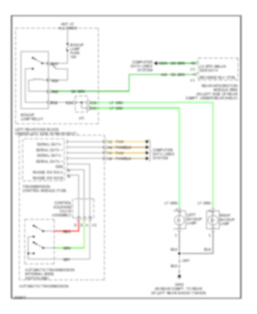
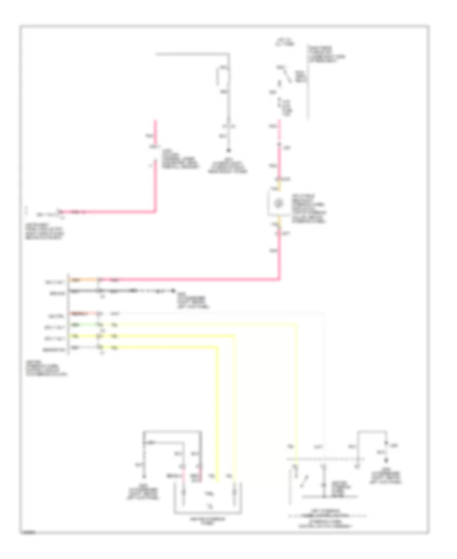
Backup Lamps Wiring Diagram for Cadillac STS V 2009
List of elements for Backup Lamps Wiring Diagram for Cadillac STS V 2009:
- A x2
- Automatic transmission
- Automatic transmission internal mode switch (ims)
- Bck/up lamp fuse 10a
- Bck/up lamp relay
- Computer data lines system
- Control solenoid valve assembly
- G402 (in rear compt, to rear of left rear shock tower)
- Gnd
- Hot at all times
- J/c
- J401
- Left backup lamp
- Left rear fuse block (under left side of rear seat)
- Lo spd gmlan ser data
- R36
- R37
- R38
- R40
- Range sw sig a
- Range sw sig b
- Rear integration module (rim) (in left side of rear compt, under rear shelf)
- Red
- Reverse rly ctrl
- Right backup lamp
- S24
- S25
- S28
- Serial data +
- Serial data -
- Tan
- Transmission control module (tcm)
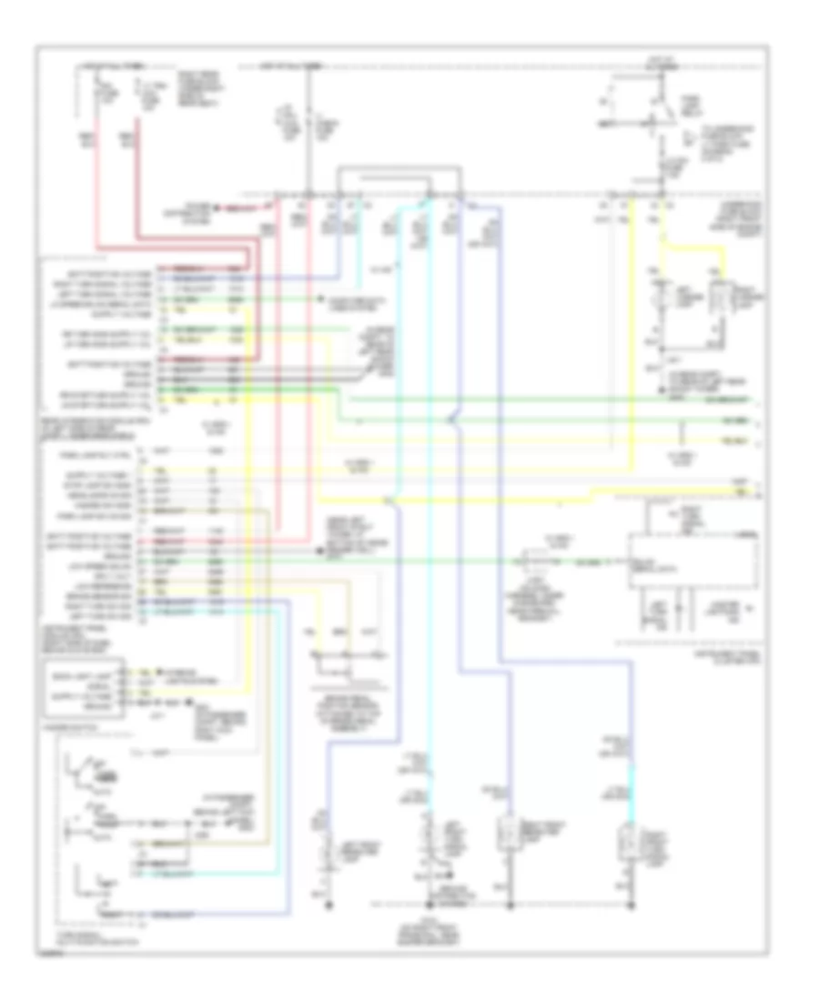
Exterior Lamps Wiring Diagram (1 of 2) for Cadillac STS V 2009
List of elements for Exterior Lamps Wiring Diagram (1 of 2) for Cadillac STS V 2009:
- (in passenger compt, behind left kick panel) g200
- (in rear compt, to rear of left rear shock tower) g402
- (near left front strut tower, at bottom of inside fender well) g101
- Auto
- Back light lamp
- Batt positive voltage
- Brake pedal position sensor (attached to top of brake pedal assembly)
- Brake sensor sig
- Computer data lines system
- G104 (on right front frame rail, near bumper bracket)
- G201 (in passenger compt, behind right kick panel)
- Gmlan serial data
- Ground
- Ground distribution system
- Hazard sw sign
- Hazard switch
- Headlamps on sig
- Hot at all times
- I/p mdl/ aldl fuse 10a
- Instrument panel cluster (ipc)
- Instrument panel module (ipm) (right side of dash, behind glove box)
- Interior lights system
- J226
- J311
- J401
- Jx201 (on dash harness, under dashboard, near firewall grommet)
- Left
- Left front repeater lamp
- Left front turn signal lamp
- Left license lamp
- Left turn signal ind
- Left turn signal voltage
- Left turn sw sig
- Lic dim fuse 7.5a
- Lo speed gmlan serial data
- Logic
- Low reference
- Low speed gmlan
- Lt trn/ ldw fuse 10a
- Master lightning ind
- Off
- Park head
- Park lamp relay
- Park lamp rly ctrl
- Park lamp sw on sig
- Power distribution system
- Rear integration module (rim) (in left side of rear compt, under rear shelf)
- Right
- Right front repeater lamp
- Right front turn signal lamp
- Right license lamp
- Right rear fuse block (under right side of rear seat)
- Right turn signal ind
- Right turn signal voltage
- Right turn sw sig
- Rim fuse 10a
- Signal
- Sply volt
- Stop lamp sw sign
- To underhood fuse block lt park fuse, (diagram 2 of 2)
- Turn signal/ multi-function switch
- Underhood fuse block (right front side of engine compt)
- V/ check fuse 10a
- W/ gps 1 & hid
- W/ hid
Exterior Lamps Wiring Diagram (2 of 2) for Cadillac STS V 2009
List of elements for Exterior Lamps Wiring Diagram (2 of 2) for Cadillac STS V 2009:
- (in body harness, 58 cm from right rear fuse block c1) j306
- (in body harness, 72 cm from right rear fuse block c1) (w/ gps 1) j317
- (right front side of engine compt) underhood fuse block
- (under right side of rear seat) right rear fuse block
- Center high mounted stop lamp (chmsl)
- Engine controls & transmissions systems
- From underhood a fuse block lic dim fuse (diagram 1 of 2)
- G104 (on right front frame rail, near bumper bracket)
- G401 (in rear compt, to rear of right rear shock tower)
- G402 (in rear compt, to rear of left rear shock tower)
- Ground
- Hot at all times
- J/c
- J108
- J109
- J401
- J409
- Left front marker lamp
- Left front park lamp
- Left headlamp
- Left rear marker lamp
- Left tail lamp
- Left tail lamp outage detection signal
- Logic
- Lt park fuse 10a
- R36
- R37
- R38
- R40
- Right front marker lamp
- Right front park lamp
- Right headlamp
- Right rear marker lamp
- Right tail lamp
- Right tail lamp outage detection signal
- Rt park fuse 10a
- S12
- S13
- S14
- Stop lamp relay
- Stop lamps fuse 10a
- W/ gps 1 & hid
GROUND DISTRIBUTION
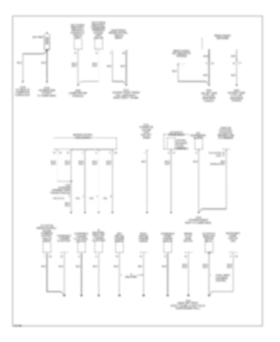
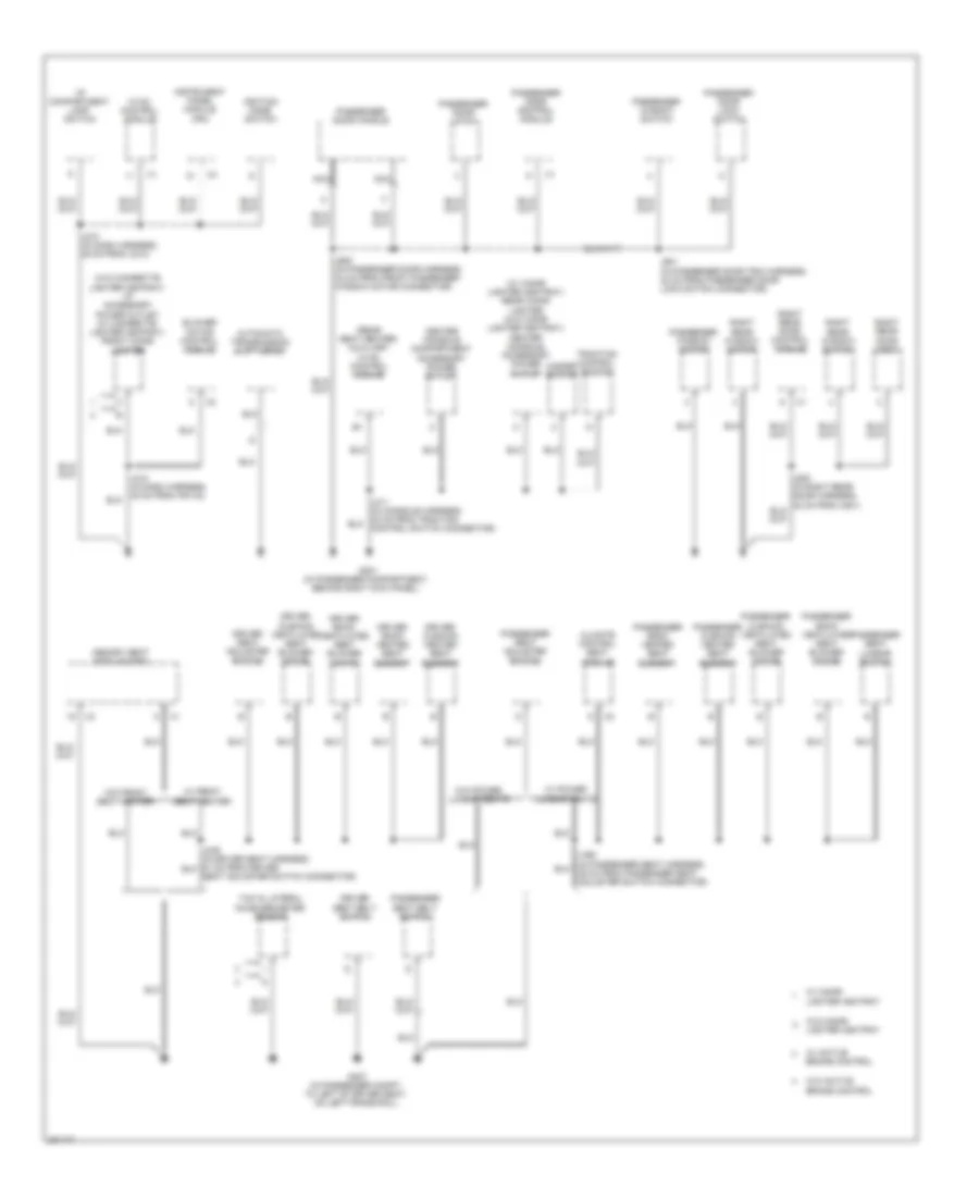
Ground Distribution Wiring Diagram (1 of 5) for Cadillac STS V 2009
List of elements for Ground Distribution Wiring Diagram (1 of 5) for Cadillac STS V 2009:
- (4.4l & 4.6l) (3.6l)
- (4.4l) charge air cooler (cac) coolant pump
- (if equipped) headlamp washer fluid pump
- (w/ active brake control) power steering control module (pscm)
- 3.6l
- 4.6l & 4.4l
- A/c compressor clutch
- Automatic headlamp dimming relay
- Automatic transmission
- B c
- Battery
- Brake fluid level switch
- Control solenoid valve assembly
- Electronic brake control module (ebcm)
- Engine control module (ecm)
- G100 (on rear side of right cylinder head)
- G101 (near left front strut tower, at bottom of inside fender well)
- G105 (at back of underhood fuse block)
- G106 (on rear side of right cylinder head)
- G110 (on right front frame rail, near right front strut tower)
- G306 (under center console)
- G403 (on right side "c" pillar, near rear window)
- G404 (on left side "c" pillar, near rear window)
- If equipped
- Inflatable restraint passenger presence system (pps) module
- Inflatable restraint sensing & diagnostic module (sdm)
- Instrument panel module (ipm)
- Intelligent high beam control
- J152 (in engine harness, near the ecm module)
- Left heated washer nozzle
- Mass air flow (maf)/ intake air temperature (iat) sensor
- Nca
- Rear window defogger
- Rear window keyless entry antenna
- Right heated washer nozzle
- Windshield washer fluid level switch
- Windshield washer fluid pump
- Windshield wiper/ washer module
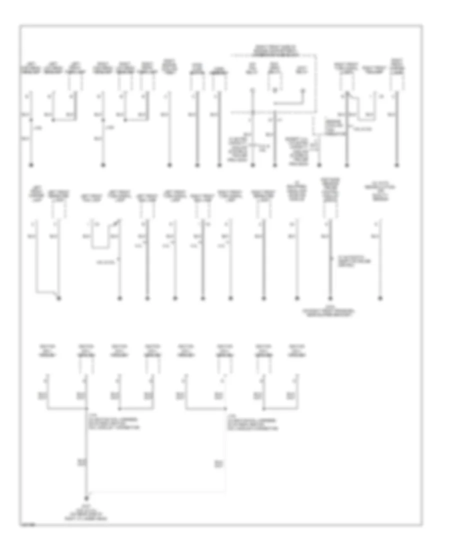
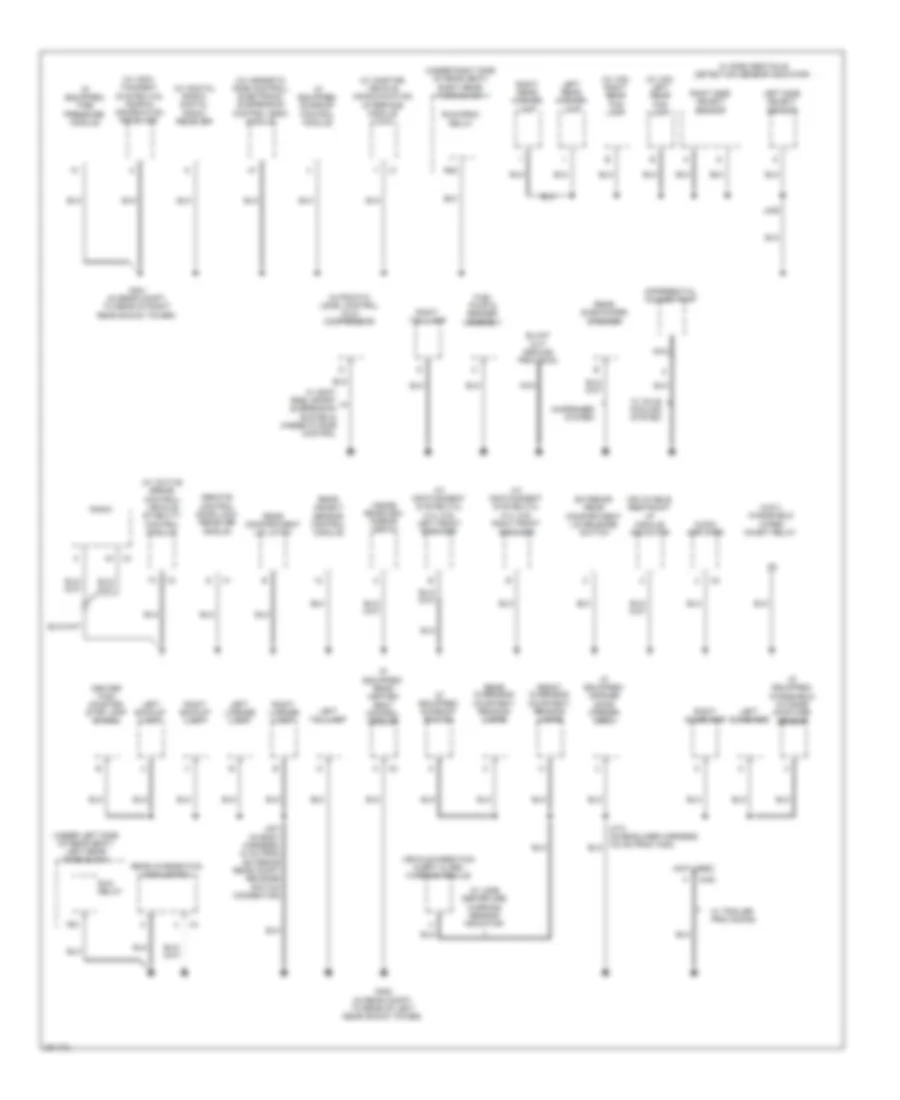
Ground Distribution Wiring Diagram (2 of 5) for Cadillac STS V 2009
List of elements for Ground Distribution Wiring Diagram (2 of 5) for Cadillac STS V 2009:
- (if equipped)
- (right front side of engine compartment) underhood fuse block
- (w/ auto recirculating) air quality sensor
- 4.4l
- 4.4l & 4.6l
- 4.6l & 3.6l
- Accy relay
- Distance sensing cruise control module (dscc)
- Engine cooling fan resistor
- Except 4.4l w/0 extra capacity cooling system & trailer provision
- G104 (on right front frame rail, near bumper bracket)
- G107 (4.6l & 4.4l) (on rear side of right cylinder head)
- Headlamp leveling module
- Hood ajar switch
- Horn assembly
- Ignition coil/ module 1
- Ignition coil/ module 2
- Ignition coil/ module 3
- Ignition coil/ module 4
- Ignition coil/ module 5
- Ignition coil/ module 6
- Ignition coil/ module 7
- Ignition coil/ module 8
- J108
- J109
- J133 (in ignition coil harness, 30 cm from ignition coil module 2 connector)
- J144 (in ignition coil harness, 39 cm from ignition coil module 1 connector)
- Left front fog lamp
- Left front marker lamp
- Left front park lamp
- Left front repeater lamp
- Left front turn signal lamp
- Left high beam headlamp
- Left low beam headlamp
- Right engine cooling fan
- Right front fog lamp
- Right front marker lamp
- Right front park lamp
- Right front repeater lamp
- Right front turn signal lamp
- Right high beam headlamp
- Right low beam headlamp
- Run crnk relay
- S/p fan relay
- W/ automatic adaptive cruise control
- W/ extra capacity cooling system & trailer provision
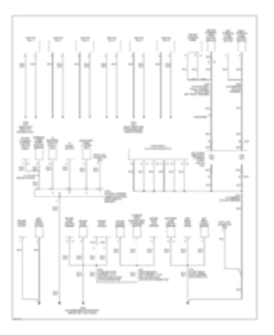
Ground Distribution Wiring Diagram (3 of 5) for Cadillac STS V 2009
List of elements for Ground Distribution Wiring Diagram (3 of 5) for Cadillac STS V 2009:
- (if equipped) head up display (hud)
- Data link connector (dlc)
- Driver door control module
- Driver door handle
- Driver door latch
- Driver door lock switch
- Driver window motor
- Driver window switch
- G109 (3.6l) (near right front of engine block)
- G112 (3.6l) (right rear side of engine block, near starter)
- G200 (in passenger compartment, behind left kick panel)
- Heated steering wheel
- Heated steering wheel control module
- I/p dimmer switch
- If equipped
- Ignition coil 1
- Ignition coil 2
- Ignition coil 3
- Ignition coil 4
- Ignition coil 5
- Ignition coil 6
- Inflatable restraint steering wheel module coil
- Instrument panel cluster (ipc)
- Interior rear compartment lid release switch
- J201
- J202 (in instrument panel harness, 50.5 cm from left front speaker)
- J224 (in steering column harness)
- J228 (in steering column harness)
- J500 (in driver door harness, 32 cm from driver window motor connector)
- J501 (in driver door trim harness, 47 cm from driver door lock switch connector)
- J700 (in left rear door harness, 32 cm from x701)
- Jx201 (on dash harness, under dashboard, near firewall grommet)
- Left rear door control module
- Left rear door latch
- Left rear window motor
- Left rear window switch
- Left steering wheel control switch
- Nca
- Power steering control module (pscm)
- Right steering wheel control switch
- Steering wheel speed/ position sensor
- Turn signal/ multifunction switch
- W/ active brake control
- X276
- X277
Ground Distribution Wiring Diagram (4 of 5) for Cadillac STS V 2009
List of elements for Ground Distribution Wiring Diagram (4 of 5) for Cadillac STS V 2009:
- (rear seat heater) auxiliary hvac control module
- (w/ cigar lighter ashtray) rear cigar lighter (w/o cigar lighter ashtray) center console accessory power outlet
- (w/o cigarette lighter ashtray) i/p accessory power outlet (w/ cigarette lighter ashtray) front cigar lighter
- Automatic transmission shift lever
- Blower motor control module
- Center console compartment accessory power outlet
- Climate control seat module
- Driver back heated seat element
- Driver back ventilated seat blower motor
- Driver cushion heated seat element
- Driver cushion ventilated seat blower motor
- Driver seat adjuster switch
- Driver seat belt switch
- G201 (in passenger compartment, behind right kick panel)
- G307 (in passenger compt, to left of driver seat, on left frame rail)
- Hazard switch
- Hvac control module
- I/p compartment lamp switch
- Ignition mode switch
- Instrument panel module (ipm)
- J210 (in dash harness, 35 cm from x214)
- J600 (in passenger door harness, 32 cm from front passenger window motor connector)
- J601 (in passenger door trim harness, 42 cm from passenger door lock switch connector)
- Memory seat module (msm)
- Nca
- Passenger back heated seat element
- Passenger back ventilated seat blower motor
- Passenger cushion heated seat element
- Passenger cushion ventilated seat blower motor
- Passenger door control module
- Passenger door handle
- Passenger door latch
- Passenger door lock switch
- Passenger seat adjuster switch
- Passenger seat belt switch
- Passenger seat lumbar switch
- Passenger window motor
- Passenger window switch
- Right rear door control module
- Right rear door lock
- Right rear window motor
- Right rear window switch
- Seat adjuster switch connector)
- Traction control switch
- W/ active brake control
- W/ cigar lighter ashtray
- W/ front seat heater
- W/ power lumbar seats
- W/o active brake control
- W/o cigar lighter ashtray
- W/o front seat heater
- W/o power lumbar seats
- Yaw & lateral accelerometer sensor
Ground Distribution Wiring Diagram (5 of 5) for Cadillac STS V 2009
List of elements for Ground Distribution Wiring Diagram (5 of 5) for Cadillac STS V 2009:
- (if equipped) garage door opener (gdo)
- (if equipped) rear heated seat control module
- (if equipped) sunroof control module
- (if equipped) sunroof switch
- (if equipped) tire pressure module
- (if equipped) windshield outside moisture sensor
- (not used)
- (under left side of rear seat) left rear fuse block
- (under right side of rear seat) right rear fuse block
- (w/ active brake control) vehicle stability control module
- (w/ digital radio) digital radio receiver
- (w/ hid) left rear fog lamp
- (w/ hid) right rear fog lamp
- (w/ info- tainment system 015) traffic information receiver
- (w/ infotainment system 012, 014, 015) left front speaker
- (w/ infotainment system 012, 014, 015) right front speaker
- (w/ magnetic ride control) electronic suspension control (esc) module
- (w/ onstar) vehicle communication interface module (vcim)
- (wcv) windshield wiper inhibit relay
- 15-speaker system
- Audio amplifier
- Automatic level control (alc) compressor
- Center high mounted stop lamp (chmsl)
- Differential cooler pump
- Exterior rear compartment lid release switch
- Front overhead courtesy/ reading lamps
- Fuel pump & sender assembly
- G401 (in rear compt, to rear of right rear shock tower)
- G402 (in rear compt, to rear of left rear shock tower)
- Inflatable restraint i/p module indicator
- Inside rearview mirror (isrvm)
- J401 (in body harness, 15 cm from exterior rear compt release switch connector)
- J409
- Left backup lamp
- Left license lamp
- Left rear marker lamp
- Left side object sensor
- Left sunshade
- Left tail lamp
- Nca
- R21
- R25
- Radio
- Rear compartment lid latch
- Rear integration module (rim)
- Rear object sensor control module
- Rear overhead courtesy/ reading lamps
- Rear subwoofer speaker
- Remote control door lock receiver (rcdlr)
- Right backup lamp
- Right license lamp
- Right rear marker lamp
- Right side object sensor
- Right sunshade
- Right tail lamp
- Run relay
- Run/crnk relay
- Vehicle direction alert alarm warning module
- W/ axle cooling system
- W/ lane departure warning sensor indicator
- W/ side obstacle detection sensor indicator
- W/ soft ride, sport suspension system & magnetic ride control
- W/ trailer provisions
- X402
HEADLIGHTS
Headlamps Wiring Diagram (1 of 2) for Cadillac STS V 2009
List of elements for Headlamps Wiring Diagram (1 of 2) for Cadillac STS V 2009:
- (in dash harness, 51 cm from left front dash speaker connector) j202
- Air conditioning system
- Auto
- Automatic headlamp dimming relay (w/ intelligent high beam) (on underhood fuse block)
- C (not used)
- Computer data lines system
- Flash to pass sw sig
- Fog lamp rly ctrl
- Fog lamp sw sig
- Fog lamps ind
- Front fog lamp switch
- Ftp
- G101 (near left front strut tower, at bottom of inside fender well)
- G200 (in passenger compt, behind left kick panel)
- Gmlan
- Gmlan ser data
- Head
- Headlamp on sig
- Hi beam relay
- Hi beam sw sig
- High
- High beam ind
- High beam rly ctrl
- Hot at all times
- Hvac control module (center of dash, below radio)
- I/beam fuse 15a
- Inside rearview mirror (isrvm)
- Instrument panel cluster (ipc)
- Instrument panel module (ipm) (right side of dash, behind glove box)
- J114
- Jx201 (on dash harness, under dashboard, near firewall grommet)
- Lo beam relay
- Logic
- Low
- Low beam rly ctrl
- Low ref
- Lt hi beam fuse 10a
- Lt lo beam fuse 20a
- Off
- Park
- Pwm sig
- Rly ctrl
- Rt hi beam fuse 10a
- Rt lo beam fuse 20a
- Sensor sig
- Sentinel display
- Ser data
- Serial data x1
- Sply voltage
- Sunload sensor (center of dash, in defroster grille)
- Turn signal/ multi-function switch
- Underhood fuse block (right front side of engine compt)
- W/ high intensity discharge
- W/ intelligent high beam control
- W/o high intensity discharge
- W/o intelligent high beam control
- Wiper sw on signal
- Wiper sw signal 2
- Wiper/washer system
Headlamps Wiring Diagram (2 of 2) for Cadillac STS V 2009
List of elements for Headlamps Wiring Diagram (2 of 2) for Cadillac STS V 2009:
- 4.4l
- Except 4.4l
- Fog lamp fuse 15a
- Fog lamp relay
- G104 (on right front frame rail, near bumper bracket)
- Hot at all times
- Left front fog lamp
- Left front turn signal lamp
- Left headlamp
- Left headlamp ballast
- Left high beam headlamp
- Right front fog lamp
- Right front turn signal lamp
- Right headlamp
- Right headlamp ballast
- Right high beam headlamp
- Underhood fuse block (right front side of engine compt)
HORN
Horn Wiring Diagram for Cadillac STS V 2009
List of elements for Horn Wiring Diagram for Cadillac STS V 2009:
- G104 (on right front frame rail, near bumper bracket)
- G200 (in passenger compt, behind left kick panel)
- High note horn
- Horn assembly (left front corner of vehicle)
- Horn fuse 15a
- Horn relay
- Horn relay control
- Horn switch
- Hot at all times
- Inflatable restraint steering wheel module coil (top of steering column, behind steering wheel)
- Instrument panel module (ipm) (right side of dash, behind glove box)
- Low note horn
- Nca
- Tan
- Underhood fuse block (right front side of engine compartment)
- X276
- X277
INSTRUMENT CLUSTER
3.6L VIN V
3.6L VIN V, Instrument Cluster Wiring Diagram (1 of 2) for Cadillac STS V 2009
List of elements for 3.6L VIN V, Instrument Cluster Wiring Diagram (1 of 2) for Cadillac STS V 2009:
- (in middle rear of right rear door) right rear door latch
- (in passenger compt, behind right kick panel) g201
- Abs ind
- Air bag ind
- Air bag/ ign fuse 10a
- Audible alarm
- Backlighting ctrl
- Backlighting ind
- Batt pos volt
- Brake fluid level switch (in master cylinder reservoir)
- Brake ind
- Charge ind
- Chk eng ind ctrl
- Class 2 (ecm)
- Computer data lines system
- Cruise ind
- Dic sw low ref
- Dic sw sig
- Dic toggle sw
- Door open sw sig
- Driver information center (dic) display
- Ecm/tcm ign fuse 15a
- Ekm/i/p mdl fuse 10a
- Engine controls system
- Engine coolant temperature ind
- Front fog lamps ind
- Fuel level gauge
- G101 (near left front strut tower, at bottom of inside fender well)
- G201 (in passenger compt, behind right kick panel)
- Gmlan
- Gmlan (ebcm)
- Gmlan (ecm)
- Gmlan (ipm)
- Gmlan (rim)
- Gmlan (sdm)
- Gmlan (tcm)
- Gmlan serial
- Ground
- High beam ind
- Hot at all times
- Hot w/ run crnk relay energized
- Hot w/run/crnk relay energized
- Hud fuse 10a
- Ign 1 volt
- Inflatable restraint i/p module indicator
- Instrument panel cluster (ipc)
- Ipc
- J/c
- J600
- J800
- Lane departure warning ind
- Left turn ind
- Logic
- Low spd gmlan data
- Low tire pressure ind
- Malfunction ind
- Oil level ind
- Park lights ind
- Pass seat belt ind
- Pass seat belt ind ctrl
- Passenger door control module (inside passenger's door)
- Passenger door latch (in middle rear of left rear door)
- Pnk
- Power distribution system
- Right rear door control module (inside right rear door)
- Right rear fuse block (under right side of rear seat)
- Right turn ind
- S18
- S20
- Seat belt ind
- Security ind
- Sensor signal
- Speedometer gauge
- Tachometer gauge
- Tap up/ down enable ind
- Temperature gauge
- Traction off ind
- Underhood fuse block (right front side of engine compt)
3.6L VIN V, Instrument Cluster Wiring Diagram (2 of 2) for Cadillac STS V 2009
List of elements for 3.6L VIN V, Instrument Cluster Wiring Diagram (2 of 2) for Cadillac STS V 2009:
- (in fuel tank jumper tan
- (in fuel tank) fuel pump & sender assembly
- (top left of fuel tank) secondary fuel level sensor
- 5v ref
- Auto
- Battery positive volt
- Computer data lines system
- Courtesy lmp sw on sig
- Display
- Door open sw sig
- Driver door control module (inside driver's door)
- Driver door latch (in middle rear of driver door)
- Eng/ met
- Engine control module (ecm) (front of engine, on right valve cover)
- Engine controls system
- Engine oil pressure (eop) sensor (on left side of engine, attached to oil filter adapter housing)
- G200 (in passenger compt, behind left kick panel)
- Gmlan serial data
- Ground
- Ground distribution system
- Harness, 28 cm from fuel tank pressure sensor connector) j406
- Head up display (hud)
- Hud switch low ref
- I/p dimmer sw sig
- I/p dimmer switch
- Image dn
- Image up
- Info dn
- Info reset
- Info up
- Instrument panel module (ipm) (right side of dash, behind glove box)
- Interior lights system
- J500
- J700
- Jx201 (on dash harness, under dashboard, near firewall grommet)
- Left rear door control module (inside left rear door)
- Left rear door latch (in middle rear of passenger door)
- Lo spd gmlan serial data
- Logic
- Low ref
- Low spd gmlan data
- Night vision image dimming
- Night vision image down
- Night vision image up sig
- Oil sw sig
- Park brake switch (at base of brake pedal)
- Pk brk sw sig
- Pnk
- Sensor sig
- Serial data +
- Serial data -
- Tan
- Trip a/b
- Trip reset
- W/ head-up display
4.4L VIN D
4.4L VIN D, Instrument Cluster Wiring Diagram (1 of 2) for Cadillac STS V 2009
List of elements for 4.4L VIN D, Instrument Cluster Wiring Diagram (1 of 2) for Cadillac STS V 2009:
- (in middle rear of right rear door) right rear door latch
- (in passenger compt, behind right kick panel) g201
- Abs ind
- Air bag ind
- Air bag/ ign fuse 10a
- Audible alarm
- Backlighting ctrl
- Backlighting ind
- Batt pos volt
- Brake fluid level switch (in master cylinder reservoir)
- Brake ind
- Charge ind
- Chk eng ind ctrl
- Class 2 (ecm)
- Computer data lines system
- Cruise ind
- Dic sw low ref
- Dic sw sig
- Dic toggle sw
- Door open sw sig
- Driver information center (dic) display
- Ecm/tcm ign fuse 15a
- Ekm/i/p mdl fuse 10a
- Engine controls system
- Engine coolant temperature ind
- Front fog lamps ind
- Fuel level gauge
- G101 (near left front strut tower, at bottom of inside fender well)
- G201 (in passenger compt, behind right kick panel)
- Gmlan
- Gmlan (ebcm)
- Gmlan (ecm)
- Gmlan (ipm)
- Gmlan (rim)
- Gmlan (sdm)
- Gmlan (tcm)
- Gmlan serial
- Ground
- High beam ind
- Hot at all times
- Hot w/ run crnk relay energized
- Hot w/run/crnk relay energized
- Hud fuse 10a
- Ign 1 volt
- Inflatable restraint i/p module indicator
- Instrument panel cluster (ipc)
- Ipc
- J/c
- J600
- J800
- Lane departure warning ind
- Left turn ind
- Logic
- Low spd gmlan data
- Low tire pressure ind
- Malfunction ind
- Oil level ind
- Park lights ind
- Pass seat belt ind
- Pass seat belt ind ctrl
- Passenger door control module (inside passenger's door)
- Passenger door latch (in middle rear of left rear door)
- Pnk
- Power distribution system
- Right rear door control module (inside right rear door)
- Right rear fuse block (under right side of rear seat)
- Right turn ind
- S18
- S20
- Seat belt ind
- Security ind
- Sensor signal
- Speedometer gauge
- Tachometer gauge
- Tap up/ down enable ind
- Temperature gauge
- Traction off ind
- Underhood fuse block (right front side of engine compt)
4.4L VIN D, Instrument Cluster Wiring Diagram (2 of 2) for Cadillac STS V 2009
List of elements for 4.4L VIN D, Instrument Cluster Wiring Diagram (2 of 2) for Cadillac STS V 2009:
- (bottom center of engine oil pan) (4.4l) engine oil level/ temperature sensor
- (in fuel tank jumper harness, 28 cm from fuel tank pressure sensor connector)
- (in fuel tank) fuel pump & sender assembly
- (top left of fuel tank) secondary fuel level sensor
- 5v ref
- Auto
- Battery positive volt
- Computer data lines system
- Courtesy lmp sw on sig
- Display
- Door open sw sig
- Driver door control module (inside driver's door)
- Driver door latch (in middle rear of driver door)
- Eng/ met
- Engine control module (ecm) (on left front frame rail, below left headlamp assembly)
- Engine controls system
- Engine oil pressure (eop) sensor (on left side of engine)
- G200 (in passenger compt, behind left kick panel)
- Gmlan serial data
- Ground
- Ground distribution system
- Head up display (hud)
- Hud switch low ref
- I/p dimmer sw sig
- I/p dimmer switch
- Image dn
- Image up
- Info dn
- Info reset
- Info up
- Instrument panel module (ipm) (right side of dash, behind glove box)
- Interior lights system
- J406
- J500
- J700
- Jx201 (on dash harness, under dashboard, near firewall grommet)
- Left rear door control module (inside left rear door)
- Left rear door latch (in middle rear of passenger door)
- Lo spd gmlan serial data
- Logic
- Low ref
- Low spd gmlan data
- Night vision image dimming
- Night vision image down
- Night vision image up sig
- Oil sw sig
- Park brake switch (at base of brake pedal)
- Pk brk sw sig
- Pnk
- Sensor sig
- Serial data +
- Serial data -
- Tan
- Temp sensor
- Trip a/b
- Trip reset
- W/ head-up display
4.6L VIN A
4.6L VIN A, Instrument Cluster Wiring Diagram (1 of 2) for Cadillac STS V 2009
List of elements for 4.6L VIN A, Instrument Cluster Wiring Diagram (1 of 2) for Cadillac STS V 2009:
- (in middle rear of right rear door) right rear door latch
- (in passenger compt, behind right kick panel) g201
- Abs ind
- Air bag ind
- Air bag/ ign fuse 10a
- Audible alarm
- Backlighting ctrl
- Backlighting ind
- Batt pos volt
- Brake fluid level switch (in master cylinder reservoir)
- Brake ind
- Charge ind
- Chk eng ind ctrl
- Class 2 (ecm)
- Computer data lines system
- Cruise ind
- Dic sw low ref
- Dic sw sig
- Dic toggle sw
- Door open sw sig
- Driver information center (dic) display
- Ecm/tcm ign fuse 15a
- Ekm/i/p mdl fuse 10a
- Engine controls system
- Engine coolant temperature ind
- Front fog lamps ind
- Fuel level gauge
- G101 (near left front strut tower, at bottom of inside fender well)
- G201 (in passenger compt, behind right kick panel)
- Gmlan
- Gmlan (ebcm)
- Gmlan (ecm)
- Gmlan (ipm)
- Gmlan (rim)
- Gmlan (sdm)
- Gmlan (tcm)
- Gmlan serial
- Ground
- High beam ind
- Hot at all times
- Hot w/ run crnk relay energized
- Hot w/run/crnk relay energized
- Hud fuse 10a
- Ign 1 volt
- Inflatable restraint i/p module indicator
- Instrument panel cluster (ipc)
- Ipc
- J/c
- J600
- J800
- Lane departure warning ind
- Left turn ind
- Logic
- Low spd gmlan data
- Low tire pressure ind
- Malfunction ind
- Oil level ind
- Park lights ind
- Pass seat belt ind
- Pass seat belt ind ctrl
- Passenger door control module (inside passenger's door)
- Passenger door latch (in middle rear of left rear door)
- Pnk
- Power distribution system
- Right rear door control module (inside right rear door)
- Right rear fuse block (under right side of rear seat)
- Right turn ind
- S18
- S20
- Seat belt ind
- Security ind
- Sensor signal
- Speedometer gauge
- Tachometer gauge
- Tap up/ down enable ind
- Temperature gauge
- Traction off ind
- Underhood fuse block (right front side of engine compt)
4.6L VIN A, Instrument Cluster Wiring Diagram (2 of 2) for Cadillac STS V 2009
List of elements for 4.6L VIN A, Instrument Cluster Wiring Diagram (2 of 2) for Cadillac STS V 2009:
- (bottom center of engine oil pan) (4.4l) engine oil level/ temperature sensor
- (in fuel tank jumper harness, 28 cm from fuel tank pressure sensor connector)
- (in fuel tank) fuel pump & sender assembly
- (top left of fuel tank) secondary fuel level sensor
- 5v ref
- Auto
- Battery positive volt
- Computer data lines system
- Courtesy lmp sw on sig
- Display
- Door open sw sig
- Driver door control module (inside driver's door)
- Driver door latch (in middle rear of driver door)
- Eng/ met
- Engine control module (ecm) (on left front frame rail, below left headlamp assembly)
- Engine controls system
- Engine oil pressure (eop) sensor (on left side of engine)
- G200 (in passenger compt, behind left kick panel)
- Gmlan serial data
- Ground
- Ground distribution system
- Head up display (hud)
- Hud switch low ref
- I/p dimmer sw sig
- I/p dimmer switch
- Image dn
- Image up
- Info dn
- Info reset
- Info up
- Instrument panel module (ipm) (right side of dash, behind glove box)
- Interior lights system
- J406
- J500
- J700
- Jx201 (on dash harness, under dashboard, near firewall grommet)
- Left rear door control module (inside left rear door)
- Left rear door latch (in middle rear of passenger door)
- Lo spd gmlan serial data
- Logic
- Low ref
- Low spd gmlan data
- Night vision image dimming
- Night vision image down
- Night vision image up sig
- Oil sw sig
- Park brake switch (at base of brake pedal)
- Pk brk sw sig
- Pnk
- Sensor sig
- Serial data +
- Serial data -
- Tan
- Temp sensor
- Trip a/b
- Trip reset
- W/ head-up display
INTERIOR LIGHTS
Courtesy Lamps Wiring Diagram (1 of 2) for Cadillac STS V 2009
List of elements for Courtesy Lamps Wiring Diagram (1 of 2) for Cadillac STS V 2009:
- Computer data lines system
- Courtesy lamp ctrl
- Courtesy rly ctrl
- Courtesy sply ctrl
- Front overhead console courtesy/ reading lamps
- G201 (in passenger compt, behind right kick panel)
- G402 (in rear compt, to rear of left rear shock tower)
- Gmlan serial data
- Hot at all times
- I/p compart- ment lamp
- I/p compartment lamp switch
- Int lamp fuse 10a
- Int lamp relay
- J210
- J215 (in dash harness, 65 cm from x200)
- J308 (in headliner harness, 82 cm from x308)
- J309 (in headliner harness, 92 cm from x308)
- J310
- Left i/p courtesy lamp
- Left rear door courtesy lamp
- Left sun- shade
- Nca
- R17
- R18
- R19
- R20
- Rear compart- ment courtesy lamp
- Rear compartment lid release actuator
- Rear integration module (rim) (in left side of rear compt, under rear shelf)
- Rear overhead console courtesy/ reading lamps
- Right i/p courtesy lamp
- Right rear door courtesy lamp
- Right rear fuse block (under right side of rear seat)
- Right sun- shade
- Splice pack jx300 (on left frame rail, near left side of passenger seat)
- Splice pack jx303 (in passenger compt, on right frame rail, near right side of passenger seat)
- Trunk diode
Courtesy Lamps Wiring Diagram (2 of 2) for Cadillac STS V 2009
List of elements for Courtesy Lamps Wiring Diagram (2 of 2) for Cadillac STS V 2009:
- Ajar
- Amplifier powered woofer ctrl
- Computer data lines system
- Courtesy lamp ctrl high
- Courtesy lamp ctrl low
- Courtesy lamp sw on
- Driver door control module (inside driver's door)
- Driver door latch (in middle rear of driver door)
- G200 (in passenger compt, behind left kick panel)
- G201 (in passenger compt, behind right kick panel)
- Gmlan serial data
- I/p dimmer switch
- Instrument panel module (ipm) (right side of dash, behind glove box)
- J500
- J600
- J700
- J800
- Left front door courtesy lamp
- Left rear door control module (inside left rear door)
- Left rear door latch (in middle rear of passenger door)
- Lf door ajar
- Low reference
- Lr door ajar sw sig
- Passenger door control module (inside passenger's door)
- Passenger door latch (in middle rear of left rear door)
- Rf door ajar sw sig
- Right front door courtesy lamp
- Right rear door control module (inside right rear door)
- Right rear door latch (in middle rear of right rear door)
- Rr door ajar sw sig
Instrument Illumination Wiring Diagram (1 of 2) for Cadillac STS V 2009
List of elements for Instrument Illumination Wiring Diagram (1 of 2) for Cadillac STS V 2009:
- (in driver door trim harness, 71 cm from driver door lock switch connector) j504
- (on dash harness, under dashboard, near firewall grommet) splice pack jx201
- Auto
- B (not used) x215
- Backlight dimming ctrl
- Backlight lamp ctrl
- Backlighting control
- Backlighting ind (8 bulbs)
- Batt pos volt
- Computer data lines system
- Courtesy lamp on sig
- Dimmer sw sig
- Driver door control module (inside driver's door)
- Driver door lock switch
- Driver window switch
- Ekm/i/p mdl fuse 10a
- G101 (near left front strut tower, at bottom of inside fender well)
- G200 (in passenger compt, behind left kick panel)
- G201 (in passenger compt, behind right kick panel)
- Gmlan serial data
- Ground
- Head
- Hot at all times
- Hvac control module (center of dash, below radio)
- I/p dimmer switch
- I/p mdl/ aldl fuse 10a
- Instrument panel cluster (ipc)
- Instrument panel module (ipm) (right side of dash, behind glove box)
- Interior rear compartment lid release switch
- J210
- J226
- J501
- J601
- Lamp ctrl sply vol
- Lic dim fuse 7.5a
- Logic
- Low reference
- Off
- Park
- Park lamp rly ctrl
- Passenger door control module (inside passenger's door)
- Passenger door lock switch
- Passenger window switch
- Power distribution system
- Prk lamp relay
- Radio
- Splice pack jx201 (on dash harness, under dashboard, near firewall grommet)
- Turn signal/ multi-function switch
- Underhood fuse block (right front side of engine compt)
Instrument Illumination Wiring Diagram (2 of 2) for Cadillac STS V 2009
List of elements for Instrument Illumination Wiring Diagram (2 of 2) for Cadillac STS V 2009:
- (in passenger compt, behind left kick panel) g200
- (in steering column harness) j227
- (in steering column harness) j228
- (on left frame rail, near left side of passenger seat) splice pack jx300
- Automatic transmission shift lever assembly
- Auxiliary hvac control module (w/ heated seat)
- Backlight lamp ctrl
- Computer data lines system
- F x276
- F x277
- From x212)
- Fuse 2a
- G200 (in passenger compt, behind left kick panel)
- G201 (in passenger compt, behind right kick panel)
- G402 (in rear compt, to rear of left rear shock tower)
- Gmlan serial data
- Hazard switch
- Ignition mode switch
- Inflatable restraint steering wheel module coil (top of steering column, behind steering wheel)
- J210
- J224
- J310
- J311
- J700
- J800
- Left rear door control module (inside left rear door)
- Left rear window switch
- Left steering wheel control switch
- Nca
- Right rear door control module (inside right rear door)
- Right rear window switch
- Right steering wheel control switch
- Splice pack jx201 (on dash harness, under dashboard, near firewall grommet)
- Steering column fuse block
- Sunroof switch (if equipped)
- Traction control switch
MEMORY SYSTEMS
Driver"s Mirror Wiring Diagram for Cadillac STS V 2009
List of elements for Driver"s Mirror Wiring Diagram for Cadillac STS V 2009:
- (inside driver door)
- 5v feed
- 5v ref
- 5v rtn
- Bat pos voltage
- Computer data lines system
- Ddm fuse 15a
- Driver door control module (ddm)
- Driver outside rearview mirror
- Driver window switch
- Drvr horiz pos sens sig
- Drvr vert pos sens sig
- G200 (in passenger compt, behind left kick panel)
- Gnd
- Ground
- Horiz motor
- Horiz pos sens
- Horiz pos sensor
- Hot at all times
- J500
- J501
- Left horiz
- Left rear fuse block (under left side of rear seat)
- Lft mir mtr dn ctrl
- Lft mir mtr lft ctrl
- Lft mir mtr up/rt ctrl
- Logic
- Low ref
- Low spd gmlan serial data
- Navigation system
- Right horiz
- Vert down
- Vert motor
- Vert pos sens
- Vert pos sensor
- Vert up
- W/ infotainment system 010
Memory Power Tilt & Power Telescopic Wiring Diagram for Cadillac STS V 2009
List of elements for Memory Power Tilt & Power Telescopic Wiring Diagram for Cadillac STS V 2009:
- (in driver seat harness, 21 cm from driver seat adjuster motor assembly c2)
- (in driver seat harness, 25 cm from x300)
- (in steering column harness)
- (in steering column)
- Bat pos voltage
- Computer data lines system
- Driver seat adjuster motor assembly (under driver seat cushion)
- Driver seat lumbar motor assembly
- Driver seat recline motor assembly (under driver seat)
- Drv pwr seat ft vert mtr dn ctrl
- Drv pwr seat rear vert mtr dn ctrl
- G307 (in passenger compt, to left of driver seat, on left frame rail)
- Gnd
- Hot at all times
- Hud fuse 10a
- Instrument panel module (ipm) (right side of dash, behind glove box)
- J227
- J302
- J352 (in driver seat harness, 20 cm from driver seat adjuster motor assembly connector)
- J356
- J363
- Left rear fuse block (under left side of rear seat)
- Low spd gmlan serial data
- Mem mirror position sens 5v ref
- Mem seat/mirror sens low ref
- Memory seat module (msm) (under driver seat)
- Pnk
- Power distribution system
- Pwr seats circuit breaker 30a
- Red
- S362 (in driver seat harness, 16 cm from x300)
- Steering column tele mtr sig
- Steering column telescope actuator
- Steering column tilt motor
- Steering column tilt mtr sig
- Steering column tilt mtr up ctrl
- Steering wheel tilt actuator (in steering column)
- Steering wheel/ column tilt/ telescope switch
- Strg col tilt & tele dn sw sig
- Strg col tilt & tele fwd sw sig
- Strg col tilt & tele rwd sw sig
- Strg col tilt & tele up sw sig
- Tan
- Telescope in
- Telescope out
- Tilt down
- Tilt up
- Underhood fuse block (right front side of engine compt)
Memory Seat Wiring Diagram (1 of 2) for Cadillac STS V 2009
List of elements for Memory Seat Wiring Diagram (1 of 2) for Cadillac STS V 2009:
- (if equipped) driver seat lumbar switch
- Bat pos voltage
- Battery positive voltage
- Computer data lines system
- Down
- Driver seat adjuster switch
- Drv mem st recline mtr pos sens sig
- Drv pwr seat frt vert mtr dn ctrl
- Drv pwr seat frt vert mtr up ctrl
- Drv pwr seat horiz mtr fwd ctrl
- Drv pwr seat horiz mtr rwd ctrl
- Drv pwr seat lumbar mtr fwd ctrl
- Drv pwr seat lumbar mtr rwd ctrl
- Drv pwr seat lumbar mtr up ctrl
- Drv pwr seat rear vert mtr dn ctrl
- Drv pwr seat rear vert mtr up ctrl
- Drv pwr seat recline mtr fwd ctrl
- Drv pwr seat recline mtr rwd ctrl
- Drv seat lumbar dn sw sig
- Drv seat lumbar fwd sw sig
- Drv seat lumbar rwd sw sig
- Drv st lumbar up sw sig
- For- ward
- Front vertical down
- Front vertical up
- Frt vert dn sw sig
- Frt vert up sw sig
- G307 (in passenger compt, to left of driver seat, on left frame rail)
- Gnd
- Horiz fwd sw sig
- Horiz rwd sw sig
- Horizontal forward
- Horizontal rearward
- Hot at all times
- J302
- J349 (w/ front heated seats)
- J354
- Left rear fuse block (under left side of rear seat)
- Low spd gmlan serial data
- Mem mirror pos sens 5v ref
- Mem seat/mirror sens low ref
- Mem st frt vert mtr pos sens sig
- Mem st horiz mtr pos sens sig
- Mem st lumbar horiz pos sens sig
- Mem st lumbar vert pos sens sig
- Mem st rr vert mtr pos sens sig
- Memory power tilt & power telescopic circuit
- Memory seat module (under driver seat)
- Msm fuse 10a
- Pnk
- Pwm serial data
- Pwr seats circuit breaker 30a
- Rear vert dn sw sig
- Rear vert up sw sig
- Rear vertical down
- Rear vertical up
- Rear- ward
- Recline forward
- Recline rearward
- Seat recline mtr fwd ctrl
- Seat recline mtr rwd ctrl
- Steering column tele mtr fwd
- Steering column tele mtr sig
- Steering column tilt mtr sig
- Steering column tilt mtr up ctrl
- Tan
Memory Seat Wiring Diagram (2 of 2) for Cadillac STS V 2009
List of elements for Memory Seat Wiring Diagram (2 of 2) for Cadillac STS V 2009:
- (in driver seat harness, 16 cm from x300) j362
- (in driver seat harness, 20 cm from driver seat adjuster motor assembly connector) j352
- (in driver seat harness, 25 cm from x300) j356
- (in driver seat harness, 39 cm from driver seat recline motor connector)
- (under driver seat cushion) (if equipped) driver seat adjuster motor assembly
- Climate control seat module (under right front seat)
- Driver lumbar position sensors
- Driver seat front vertical motor
- Driver seat front vertical position sensor
- Driver seat horizontal motor
- Driver seat horizontal position sensor
- Driver seat lumbar motor assembly (if equipped) (in driver seat back)
- Driver seat rear vertical motor
- Driver seat rear vertical position sensor
- Driver seat recline motor assembly (under driver seat)
- Driver seat recline position sensor
- Horizontal
- J351 (w/ power lumber seat)
- J363 (in driver seat harness, 21 cm from driver seat adjuster motor assembly c2)
- Memory power tilt & power telescopic circuit
- Pnk
- Pwm serial data
- Red
- Tan
- Vertical
Passenger"s Mirror Wiring Diagram for Cadillac STS V 2009
List of elements for Passenger"s Mirror Wiring Diagram for Cadillac STS V 2009:
- 5v feed
- 5v ref
- 5v rtn
- Bat pos voltage
- Computer data lines system
- Ddm fuse 15a
- Driver door control module (inside driver's door)
- Driver window switch
- Frt pdm fuse 15a
- G200 (in passenger compt, behind left kick panel)
- G201 (in passenger compt, behind right kick panel)
- Gnd
- Ground
- Horiz motor
- Horiz pos sens
- Horiz pos sensor
- Hot at all times
- J500
- J501
- J600
- Left horiz
- Left rear fuse block (under left side of rear seat)
- Logic
- Low ref
- Low spd gmlan serial data
- Navigation system
- Pass horiz pos sens sig
- Pass mir mtr lft ctrl
- Pass vert pos sens sig
- Passenger door control module (inside passenger's door)
- Passenger outside rearview mirror
- Right horiz
- Right rear fuse block (under right side of rear seat)
- Rt mir mtr dn ctrl
- Rt mir mtr up/rt ctrl
- Vert down
- Vert motor
- Vert pos sens
- Vert pos sensor
- Vert up
- W/ infotainment system 010
NAVIGATION
Navigation Wiring Diagram for Cadillac STS V 2009
List of elements for Navigation Wiring Diagram for Cadillac STS V 2009:
- (or 1782)
- (or nca)
- (right rear of radio) navigation antenna
- (w/ 15 speaker) audio/video adapter
- 3.6l
- 4.4l & 4.6l
- Am/fm1
- Am/fm1 antenna signal
- Antenna
- Antenna coax x5
- Aux det sig
- Aux detect sig
- Aux vid hi sig
- Aux video hi signal x1
- Batt positive volt
- Case ground
- Cellular microphone signal
- Cellular telephone microphone sig
- Coax
- Computer data lines system
- Drain wire
- Engine control module (ecm) (3.6l: front of engine, on right valve cover) (except 3.6l: on left front frame rail, below left headlamp assembly)
- Fm1 antenna
- Fm1 antenna signal
- Fm2
- Fm2 antenna signal
- G402 (in rear compt, to rear of left rear shock tower)
- Ground
- Hot at all times
- Inside rearview mirror (isrvm)
- J/c
- Lh aux aud sig
- Lh aux audio sig
- Lo spd gmlan serial data
- Nca
- Pnk
- Radio
- Radio antenna coax
- Radio antenna module (above center rear of headliner)
- Radio rear window antenna
- Rdo/ onstar fuse 10a
- Rear object sensor control module (in left side of rear compt, under rear shelf)
- Rh aux aud sig
- Rh aux audio sig
- Right rear fuse block (under right side of rear seat)
- S15
- S17
- Vehicle communication interface module (vcim) (in rear compt, near right rear strut tower)
- Vehicle speed sig
- Vics-fm3 antenna
- Vics-fm3 antenna signal
- Voice recog aud low ref
- Voice recog low
- Voice recog sig
- W/ hid headlamps
- W/ infotainment system 012, 014 & 015
- W/ intelligent high beam control
- W/ vehicle communication system
Parking Assistant Wiring Diagram for Cadillac STS V 2009
List of elements for Parking Assistant Wiring Diagram for Cadillac STS V 2009:
- (in rear compt, to rear of left rear shock tower) g402
- Backup lamp feed
- Batt positive volt
- Bck/up lamp fuse 10a
- Bck/up lamp relay
- Center amber ind
- Center amber ind ctrl
- Computer data lines system
- Driver door control module (inside driver's door)
- Driver outside rearview mirror
- G401 (in rear compt, to rear of right rear shock tower)
- Gnd
- Ground
- Hot at all times
- Hot w/ run/crnk relay energized
- Ign 1 voltage
- J/c
- J403 (in rear fascia harness, 26 cm from right rear middle object sensor connector)
- J407
- J409
- J414 (in body harness, near rim module)
- Led sig
- Left amber ind
- Left amber ind ctrl
- Left rear corner object alarm sensor (on left rear corner of rear fascia)
- Left rear fuse block (under left side of rear seat)
- Left rear middle object alarm sensor (on left rear middle of rear fascia)
- Left side object sensor (on left rear of vehicle)
- Low reference
- Lr corner object sens sig
- Lr middle object sens sig
- Navigation circuit
- Object sens low ref
- Object sens sply voltage
- Passenger door control module (inside passenger's door)
- Passenger outside rearview mirror
- Pnk
- R36
- R37
- R38
- R40
- Rear integration module (rim) (in left side of rear compt, under rear shelf)
- Rear object sensor control module (in left side of rear compt, under rear shelf)
- Rear parking assist (rpa) diagnostic connector (green one pin connector, beneath rear shelf)
- Rear parking assist (rpa) display
- Rear parking assist chime sig
- Rear parking diagnostic sig
- Rear parking display sply volt
- Red ind
- Red ind ctrl
- Reverse relay coil feed
- Right rear corner object alarm sensor (on right rear corner of rear fascia)
- Right rear fuse block (under right side of rear seat)
- Right rear middle object alarm sensor (on right rear middle of rear fascia)
- Right side object sensor (on left rear of vehicle)
- Rim/rpa/ isrvm/clm fuse 10a
- Rr corner object sens sig
- Rr middle object sens sig
- Rt trn/ sbza fuse 10a
- S22
- S24
- S25
- S27
- Sensor signal
- Serial data
- Vehicle speed sig
PASSIVE RESTRAINTS
Passive Restraints Wiring Diagram for Cadillac STS V 2009
List of elements for Passive Restraints Wiring Diagram for Cadillac STS V 2009:
- (under center console)
- 10a
- Air bag/ batt fuse 10a
- Air bag/ ign fuse pnk
- Battery b+
- C nca
- Case ground
- Class 2 (sdm)
- Driver seat belt buckle
- Driver seat belt retractor (left "b" pillar)
- Driver seat belt switch
- Drv seat belt sw low ref
- Drv seat belt sw sig
- G306
- G307 (in passenger compt, to left of driver seat, on left frame rail)
- Gmlan serial data
- Ground
- Hot at all times
- Hot w/ run relay energized
- Hot w/ run/crnk relay energized
- Ign
- Ign 1 vol
- Ign 3 fuse 10a
- Inflatable restraint sensing & diagnostic module (sdm) (under rear of center console)
- Instrument panel cluster (ipc)
- J/c
- Left rear fuse block (under left side of rear seat)
- Lo spd gmlan serial data
- Logic
- Nca
- Pass seat belt sw sig
- Passenger seat belt buckle
- Passenger seat belt retractor (right "b" pillar)
- Passenger seat belt switch
- Pnk
- Right rear fuse block (under right side of rear seat)
- S18
- S19
- Seat belt ind
- Splice pack jx201 (on dash harness, under dashboard, near firewall grommet)
- Splice pack jx300 (on left frame rail, near left side of passenger seat)
- Splice pack jx303 (in passenger compt, on right frame rail, near right side of passenger seat)
POWER DISTRIBUTION
Power Distribution Wiring Diagram (1 of 6) for Cadillac STS V 2009
List of elements for Power Distribution Wiring Diagram (1 of 6) for Cadillac STS V 2009:
- (in passenger seat harness, 24 cm from passenger seat adjuster switch connector) j353
- (right front side of engine compt) underhood fuse block
- (under left side of rear seat) left rear fuse block
- 200a
- Abs fuse 25a
- Abs mtr fuse 50a
- Air bag/ batt fuse 10a
- Amp fuse 30a
- Audio amplifier
- Battery
- Bck/up lamp fuse 10a
- Bck/up lamp relay
- Ddm fuse 15a
- Driver back ventilated seat blower motor
- Driver cushion ventilated seat blower motor
- Driver door module (ddm)
- Driver seat adjuster switch
- Driver seat lumbar switch
- Electronic brake control module (ebcm)
- Generator
- Inflatable restraint sensing & diagnostic module (sdm)
- Inline fuse generator
- J/c
- J302 (in body harness, 58 cm from right rear fuse block c1)
- Left front speaker
- Left rear door control module
- Left rear fuse block (under left side of rear seat)
- Lpdb 1 fuse 50a
- Lpdb 2 fuse 50a
- Lt pos relay
- Memory seat module (msm)
- Memory seat module (msm) (if equipped)
- Msm fuse 10a
- Passenger seat adjuster switch
- Passenger seat lumbar switch
- Pos lamp fuse 10a
- Pwr seats circuit breaker 30a
- R13
- R18
- R26
- R29
- R31
- R32
- R36
- R37
- Rear dr mdl fuse 15a
- Rear shlf spkr fuse 15a
- Red
- Red/ (in passenger seat harness, 17 cm from passenger seat adjuster switch connector) j354
- Right rear door control module
- Rt pos relay
- S12
- S13
- S14
- S20
- S21
- S22
- S23
- Speaker
- Starter motor
- Stdby lamp relay
- Subwoofer
- To elc cmprsr fuse (diagram 2 of 6)
- To inclr pump fuse (diagram 2 of 6)
- To rpdb 2 fuse (diagram 2 of 6)
- Trunk relse relay
- Trunk relse sw fuse 7.5a
- Valet switch
- W/ climate control seats
- W/ infotainment system 010
- W/ infotainment system 012/014/015
- W/ power lumbar seat
- W/o power lumbar seat
- X1 b
Power Distribution Wiring Diagram (2 of 6) for Cadillac STS V 2009
List of elements for Power Distribution Wiring Diagram (2 of 6) for Cadillac STS V 2009:
- (in body harness, 86 cm from g306) j303
- (in passenger seat harness, 32 cm from x307) (w/ climate control seats) j355
- (not used)
- (under left side of rear seat) left rear fuse block
- (under right side of rear seat) right rear fuse block
- Automatic level control (alc) compressor
- Automatic transmission shift lever
- B x1
- C x2
- Digital radio receiver (if equipped)
- Driver seat belt retractor
- Driver window motor
- Elc cmprsr fuse 30a
- Elc cmprsr relay
- Elc exh fuse 10a
- Electronic suspension control (esc) module
- From a lpdb 1 fuse (diagram 1 of 6)
- From b pos lamp fuse (diagram 1 of 6)
- From c ddm fuse (diagram 1 of 6)
- G402 (in rear compt, to rear of left rear shock tower)
- Ign 3 fuse 10a
- Inclr pump fuse 10a
- Inclr pump relay
- J/c
- Left rear window motor
- Mrtd mdl fuse 25a
- Passenger back ventilated seat blower motor (w/ climate control seats)
- Passenger cushion ventilated seat blower motor (w/ climate control seats)
- Passenger seat belt retractor
- Passenger window motor
- R21
- R22
- R23
- R25
- Rear heated seat control module
- Rear htd/ seats fuse 20a
- Rf htd/ seat/xm fuse 20a
- Right rear window motor
- Rpdb 2 fuse 50a
- Run relay
- Seat climate control module
- Television antenna module
- To cnstr vent fuse (diagram 3 of 6)
- To jx300 (pin 31) (diagram 6 of 6)
- To rpdb 1 fuse (diagram 3 of 6)
- Traffic information receiver
- Tv/vics/ afs/scm fuse 10a
- Underhood fuse block (right front side of engine compt)
- Vehicle stability control module
- W/ active brake control
- W/ climate control seats
- W/ climate control seats & front heater seat
- W/ infotainment system
- W/ infotainment system 014/015
- W/ variable real time damping magneto rheological
- Wndw mtrs circuit breaker 30a
Power Distribution Wiring Diagram (3 of 6) for Cadillac STS V 2009
List of elements for Power Distribution Wiring Diagram (3 of 6) for Cadillac STS V 2009:
- (under right side of rear seat) right rear fuse block
- A x3
- Cnstr vent fuse 10a
- D x276
- Diff pump fuse 15a
- Diff pump relay
- Evaporative emission (evap) canister vent solenoid valve
- From d rpdb 2 fuse (diagram 2 of 6)
- From rf htd/ e seat/xm fuse (diagram 2 of 6)
- Frt pdm fuse 15a
- Fuel pump fuse 20a
- Fuel pump relay
- G401 (in rear compt, to rear of right rear shock tower)
- Harness)
- Heated steering wheel control module
- Heater steering wheel
- Htd str fuse 7.5a
- Inflatable restraint steering wheel module coil
- Inside rearview mirror (isrvm)
- Int lamp fuse 10a
- Int lamp relay
- J/c
- J221 (in steering column pnk
- J407
- Left side object sensor
- Lt trn/ ldw fuse 10a
- Passenger door control module
- Pnk
- Power steering control module
- R12
- R16
- R17
- R21
- R22
- R23
- R25
- R26
- R27
- R37
- Radio
- Rdo/ onstar fuse 10a
- Rear defog relay
- Rear integration module (rim)
- Rear object sensor control module
- Rear/ defog fuse 40a
- Red/ (in passenger door harness, 34 cm from front passenger window motor connector) j602
- Right front speaker
- Right rear fuse block (under right side of rear seat)
- Right side object sensor
- Rim fuse 10a
- Rim/rpa/ isrvm/clm fuse 10a
- Rpdb 1 fuse 50a
- Rt trn/sbza fuse 10a
- Run/ crnk fuse 10a
- Run/ crnk relay
- S/roof fuse 20a
- S10
- S11
- S15
- S16
- S17
- S22
- S23
- S24
- S25
- Steering wheel speed/ position sensor
- Stop lamp relay
- Stop lamps fuse 10a
- Sunroof control module (if equipped)
- Tan
- To afs fuse (diagram 4 of 6)
- To air bag/ ign fuse (diagram 4 of 6)
- To jx201 (pin 10) (diagram 6 of 6)
- Underhood fuse block (right front side of engine compt)
- Vehicle communication interface module (vcim) (if equipped)
- Vehicle direction alert alarm warning module
- Vehicle stability control module
- W/ active brake control
- W/ infotainment system 010
- W/ infotainment system 012/ 014/015
- W/ lane departure warning
- W/ side obstacle detection sensor indicator
- X277 d
- Yaw & lateral acceler ometer sensor
Power Distribution Wiring Diagram (4 of 6) for Cadillac STS V 2009
List of elements for Power Distribution Wiring Diagram (4 of 6) for Cadillac STS V 2009:
- (3.6l)
- (4.4l/4.6l)
- (right front side of engine compt) underhood fuse block
- (under right side of rear seat) right rear fuse block
- Afs fuse 30a
- Air bag/ign fuse 10a
- Automatic headlamp dimming relay
- Automatic transmission
- Aux outlet fuse 20a
- Center console accessory power outlet
- Center console compartment accessory power outlet
- Data link connector (dlc)
- Ecm/tcm batt fuse 10a
- Ekm/ ip mdl fuse 10a
- Engine control module (ecm)
- From f rpdb 1 fuse (diagram 3 of 6)
- From g rim/rpa/ isrvm/clm fuse (diagram 3 of 6)
- From h frt pwr outlet fuse (diagram 4 of 6)
- Front cigar lighter
- Frt pwr outlet fuse 15a
- G201 (in passenger compt, behind right kick panel)
- Hdlp wash circuit breaker 30a
- Head up display (hud) (if equipped)
- Headlamp washer fluid pump relay (w/ high intensity discharge)
- Hud fuse 10a
- I/beam fuse 15a
- I/p accessory power outlet
- I/p mdl/ aldl fuse 10a
- Inflatable restraint i/p module indicator
- Inflatable restraint passenger presence system (pps) module
- Inflatable restraint sensing & diagnostic module (sdm)
- Instrument panel cluster (ipc)
- Instrument panel module (ipm)
- J/c
- J212
- J311
- Pnk
- Power steering control module (pscm)
- Rear cigar lighter
- Red
- Remote control door lock receiver (rcdlr)
- S18
- S19
- S20
- S21
- Steering wheel/ column tilt/ telescope switch (w/ alarm taxi)
- To v/chk fuse (diagram 4 of 6)
- To wpr fuse (diagram 5 of 6)
- V/chk fuse 10a
- W/ active brake control
- W/ cigarette lighter
- W/ high beam control intelligent
- W/o cigarette lighter
- X1 h
Power Distribution Wiring Diagram (5 of 6) for Cadillac STS V 2009
List of elements for Power Distribution Wiring Diagram (5 of 6) for Cadillac STS V 2009:
- (in body harness, 55.5 cm from x305 inline connector) (w/ wiper system) j411
- (right front side of engine compt) underhood fuse block
- A/c cltch fuse 10a
- A/c cmprsr cltch relay
- Accy relay
- Blwr fuse 40a
- Ccp/ rly coils fuse 10a
- Distance sensing cruise control (dscc) module
- Fan 1 fuse 30a
- Fan 2 fuse 30a
- Fog lamp relay
- From ekm/ i i/p mdl fuse (diagram 4 of 6)
- From j blwr fuse (diagram 5 of 6)
- Frt blwr relay
- Fuel cool fuse 10a
- Fuel cool relay
- G104 (on right front frame rail, near bumper bracket)
- Headlamp leveling module (if equipped)
- Headlamp washer fluid pump relay (if equipped)
- Hi beam relay
- Hi fan spd relay
- Hid
- Horn fuse 15a
- Horn relay
- Hvac control module
- Lo beam w/o hid/ hid relay
- Lo fan spd relay
- Prk lamp relay
- Pwr/trn relay
- Rain snsr/ tpm fuse 7.5a
- Strtr fuse 30a
- Strtr relay
- Tire pressure module (if equipped)
- To instrument panel module (ipm) (pin 1 connector x2) (diagram 6 of 6)
- To pwr/trn relay (diagram 5 of 6)
- To run crnk relay (diagram 6 of 6)
- Traffic information receiver
- W/ adaptive automatic cruise control
- W/ cover wheel
- W/ infotainment system 015
- W/ tire pressure
- W/ wiper system
- W/o cover wheel
- W/o tire pressure
- Windshield outside moisture sensor (if equipped)
- Windshield wiper inhibit relay
- Windshield wiper/ washer switch
- Wpr fuse 30a
- Wpr hi relay
- Wpr spd relay
- Wpr sw/vics fuse 7.5a
- X320
Power Distribution Wiring Diagram (6 of 6) for Cadillac STS V 2009
List of elements for Power Distribution Wiring Diagram (6 of 6) for Cadillac STS V 2009:
- (not used)
- (right front side of engine compt) underhood fuse block
- 3.6l
- 4.4l & 4.6l
- Abs ign fuse 15a
- Acc ind
- Accessory voltage
- Accy ind cntrl
- Air quality sensor (if equipped)
- Automatic transmission
- Ccp fuse 10a
- Ecm/tcm ign fuse 15a
- Engine control module (ecm)
- From accy relay (diagram 5 of 6)
- From left rear fuse block (run relay) (diagram 2 of 6)
- From right rear fuse block (run/crnk relay) (diagram 3 of 6)
- From underhood fuse block n (accy relay) (diagram 5 of 6)
- G104 (on right front frame rail, near bumper bracket)
- Htd wash/ aqs fuse 10a
- Hvac control module
- Ign 1 voltage
- Ign mode sw sply volt
- Ignition mode switch
- Illum
- Instrument panel cluster (ipc)
- Instrument panel module (ipm) (right side of dash, behind glove box)
- Interior lights system
- Ipm ign mode data sig
- Ipm ign mode sw ref volt
- Jx201 (on dash harness, under dashboard, near firewall grommet)
- Jx300 (on left frame rail, near left side of passenger seat)
- Left heated washer nozzle (if equipped)
- Mode control b/u
- Off
- Off in cntrl
- Off ind
- Pnk
- Rear defog relay
- Remote control door lock receiver (rcdlr) (under rear speaker shelf)
- Right heated washer nozzle (if equipped)
- Right rear fuse block
- Right rear fuse block (under right side of rear seat)
- Run crnk relay
- Run ign 3 voltage
- Start
- Start ind
- Start ind cntrl
- Voltage b/u
POWER DOOR LOCKS
Power Door Locks Wiring Diagram (1 of 3) for Cadillac STS V 2009
List of elements for Power Door Locks Wiring Diagram (1 of 3) for Cadillac STS V 2009:
- (right side of steering column) ignition mode switch
- (under right side of rear seat) right rear fuse block
- Active ant clock sig
- Active ant data sig
- Active ant low ref
- Ant low ref 1
- Ant low ref 3
- Ant low ref 4
- Ant low ref 5
- Automatic transmission shift lever
- Backup keyless entry antenna (inside center console compt (center))
- Battery positive volt
- Coax
- Computer data lines system
- Driver information center (dic) display
- Ekm/ i/p mdl fuse 10a
- Exterior rear compartment lid release switch
- G402 (in rear compt, to rear of left rear shock tower)
- G404 (on left side "c" pillar, near rear window)
- Gmlan serial data
- Ground
- Hot at all times
- Ignition 1 voltage
- Ignition mode switch
- Instrument panel cluster (ipc)
- Jx201 (on dash harness, under dashboard, near firewall grommet)
- Keyless entry antenna (inside center console compt (rear))
- Keyless entry sig 1
- Keyless entry sig 3
- Keyless entry sig 4
- Keyless entry sig 5
- Lf door handle sw sig
- Logic
- Low speed gmlan data
- Nca
- Pnk
- R21
- Rear compartment keyless entry antenna (in back of rear bumper fascia on body (center))
- Rear window keyless entry antenna (on rear window)
- Remote control door lock receiver (rcdlr) (under rear speaker shelf)
- Rf door handle sw sig
- Run/crank relay
- Sol sply volt
- Tan
- Tire pressure ant sig
- Trunk release ctrl sig
- Underhood fuse block (right front side of engine compt)
Power Door Locks Wiring Diagram (2 of 3) for Cadillac STS V 2009
List of elements for Power Door Locks Wiring Diagram (2 of 3) for Cadillac STS V 2009:
- (behind right kick panel) g201
- (in driver door harness, 52 cm from driver window motor connector) j503
- (in passenger compt, behind left kick panel) g200
- (inside left rear door) left rear door control module
- (inside right rear door) right rear door control module
- Actuator lock ctrl
- Actuator unlock ctrl
- Back light ctr
- Battery b+
- Battery pos voltage
- Computer data lines system
- Ddm fuse 15a
- Door ajar sw sig
- Door handle sw sig
- Door key sw sig
- Door latch ctrl
- Door lock ctrl
- Door lock sig
- Door open sw sig
- Door unlatch ctrl
- Door unlock ctrl
- Door unlock sig
- Driver door control module (inside driver door)
- Driver door handle
- Driver door handle switch
- Driver door latch (in middle rear of driver door)
- Driver door lock indicator (on top rear of driver door trim panel)
- Driver door lock switch
- Driver window switch
- G200 (in passenger compt, behind left kick panel)
- Gmlan serial data
- Ground
- Hot at all times
- Illum lamp
- Interior lights system
- J/c
- J500
- J501
- J502 (w/ infotainment system 012/014/015)
- J700
- J800
- Left front door handle keyless entry antenna
- Left rear door latch (in middle rear of passenger door)
- Left rear fuse block (under left side of rear seat)
- Lock
- Logic
- Nca
- Pnk
- Pnk a
- Pnk d
- Rear dr mdl fuse 15a
- Rear lid release
- Right rear door latch (in middle rear of right rear door)
- S12
- S13
- S14
- Status ind sig gnd
- Status ind sply volt
- Tan
- Unlock
Power Door Locks Wiring Diagram (3 of 3) for Cadillac STS V 2009
List of elements for Power Door Locks Wiring Diagram (3 of 3) for Cadillac STS V 2009:
- (in passenger compt, behind left kick panel) g200
- (in passenger compt, behind right kick panel)
- (right side of dash, behind glove box) instrument panel module (ipm)
- Battery pos voltage
- Computer data lines system
- Door ajar sw sig
- Door handle sw sig
- Door latch ctrl
- Door lock sw sig
- Door open sw sig
- Door unlatch ctrl
- Door unlock sw sig
- Fd1
- Fd2
- Frt pdm fuse 15a
- G201
- G201 (in passenger compt, behind right kick panel)
- G402 (in rear compt, to rear of left rear shock tower)
- Gmlan serial data
- Ground
- Hot at all times
- Ign 1 volt
- Illu lamp
- Interior lights system
- Interior rear compartment lid release switch
- J/c
- J214 (in dash harness, 32 cm from ipm c3)
- J501
- J600
- J601
- J602 (w/ infotainment system 012/014/015)
- J603 (39 cm from front passenger window motor connector)
- Left rear fuse block (under left side of rear seat)
- Lock
- Mode data sig
- Nca
- Passenger door control module (inside passenger's door)
- Passenger door handle
- Passenger door handle switch
- Passenger door indicator (on top rear of passenger door trim panel)
- Passenger door latch (in middle rear of left rear door)
- Passenger door lock switch
- Pnk
- R31
- R32
- R33
- R35
- Rear compartment lid latch (center rear of rear compt lid)
- Rear integration module (rim) (in left side of rear compt, under rear shelf)
- Ref volt
- Right front door handle keyless entry antenna
- Right rear fuse block (under right side of rear seat)
- S20
- S21
- S22
- S23
- Status ind sig gnd
- Status ind sply volt
- Trunk ajar sig
- Trunk diode
- Trunk release ctrl
- Trunk relse relay
- Trunk relse sw fuse 7.5a
- Unlock
- Valet lockout sw
- Valet switch
POWER MIRRORS
Automatic Day/Night Mirror Wiring Diagram for Cadillac STS V 2009
List of elements for Automatic Day/Night Mirror Wiring Diagram for Cadillac STS V 2009:
- Automatic day/night mirror
- Backup lamp voltage
- Bare
- Bck/up lamp relay
- Cellular signal
- Computer data lines system
- Drain wire
- Driver door control module (ddm) (inside driver's door)
- Driver outside rearview mirror
- G402 (in rear compt, to rear of left rear shock tower)
- Gmlan serial data
- Ground
- Headlights system
- High beam dim enable
- High beam dim status
- High beam rly ctrl
- High beam sply volt
- Hot at all times
- Hot w/ run/crnk relay energized
- Ignition voltage
- Inside rearview mirror (isrvm)
- Instrument panel module (ipm) (right side of dash, behind glove box)
- J/c
- Keypad signal
- Keypad supp volt
- Led sig
- Left rear fuse block (under left side of rear seat)
- Low reference
- Mirror signal
- Pnk
- R36
- R37
- R38
- R40
- Rear integration module (rim) (in left side of rear compt, under rear shelf)
- Reverse rly coil feed
- Right rear fuse block (under right side of rear seat)
- Rim/rpa/ isrvm/clm fuse pnk 10a
- S24
- S26
- Sound systems
- Vehicle communication interface module (vcim) (if equipped) (in rear compt, near right rear strut tower)
- Vehicle speed sig
- W/ intelligent high beam control
Power Mirrors Wiring Diagram for Cadillac STS V 2009
List of elements for Power Mirrors Wiring Diagram for Cadillac STS V 2009:
- Automatic day/ night mirror low ref
- Automatic day/ night mirror sig
- Automatic day/night mirror
- Batt positive voltage
- Batt volt
- Battery
- Computer data lines system
- Ddm fuse 15a
- Defogger system
- Driver door control module (inside driver door)
- Driver outside rearview mirror
- Driver window switch
- Fold motor
- Frt pdm fuse 15a
- G200 (in passenger compt, behind left kick panel)
- G201 (in passenger compt, behind right kick panel)
- Gmlan serial data
- Ground
- Heated motor element
- Horiz motor
- Hot at all times
- J500
- J501
- J502 (w/ infotainment system 012/014/015)
- J600
- Left folding mirror motor extend control
- Left folding mirror motor retract control
- Left rear fuse block (under left side of rear seat)
- Lft mirror motor dn ctrl
- Lft mirror motor lft ctrl
- Lft mirror motor up/rt ctrl
- Logic
- Passenger door control module (inside passenger's door)
- Passenger mirror motor horiz/ver ctrl
- Passenger mirror motor horizontal ctrl
- Passenger mirror motor vertical ctrl
- Passenger outside rearview mirror
- Right folding mirror motor extend control
- Right folding mirror motor retract control
- Right rear fuse block (under right side of rear seat)
- Serial data gmlan
- Vert motor
- W/ infotainment system 010
- W/ power folding mirrors
POWER SEATS
Climate Control Seats Wiring Diagram for Cadillac STS V 2009
List of elements for Climate Control Seats Wiring Diagram for Cadillac STS V 2009:
- (in driver seat harness, 15 cm from msm c1) j358
- (in driver seat harness, 21 cm from msm c2)
- (in passenger compt, to left of driver seat, on left frame rail) g307
- (in passenger seat harness, 10 cm from passenger climate control seat module c2) j361
- (in passenger seat harness, 27 cm from passenger cushion cooled seat blower motor connector)
- (or pnk)
- Batt pos volt
- Climate control seat module (under right front seat)
- Driver back heated seat element (in driver seat back)
- Driver back ventilated seat blower motor (in driver seat back)
- Driver cushion heated seat element (in driver seat cushion)
- Driver cushion ventilated seat blower motor (in driver seat cushion)
- Fan spd cntrl
- Fan spd ctrl
- G307 (in passenger compt, to left of driver seat, on left frame rail)
- G402 (in rear compt, to rear of left rear shock tower)
- Ground
- Harness, 24 cm from passenger climate control seat module c1) j357
- Hot at all times
- Ign 3 fuse 10a
- Ign 3 volt
- Instrument panel module (ipm) (right side of dash, behind glove box)
- J/c
- J349
- J350
- J354
- J355
- J359
- J360
- Jx300 (on left frame rail, near left side of passenger seat)
- Left rear fuse block (under left side of rear seat)
- Low ref
- Memory seat module (msm) (w/ memory) (under driver seat)
- Msm fuse 10a
- Ntc sig
- Passenger back heated seat element (in passenger seat back)
- Passenger back ventilated seat blower motor (in passenger seat back)
- Passenger cushion heated seat element (in passenger seat cushion)
- Passenger cushion ventilated seat blower motor (in passenger seat cushion)
- Pnk
- Pwm data
- R21
- R22
- R23
- R25
- Rf htd/ seat/xm fuse 20a
- Right rear fuse block (under right side of rear seat)
- Run relay
- Sply vltg
- Sply volt
Front Seat Heater Wiring Diagram for Cadillac STS V 2009
List of elements for Front Seat Heater Wiring Diagram for Cadillac STS V 2009:
- (in driver seat harness, 15 cm from msm c1) j358
- (in passenger compartment, to left of driver seat, on left frame rail) g307
- (in passenger seat harness, 10 cm from passenger climate control seat module c2) j361
- (or pnk)
- (right side of dash, behind glove box) instrument panel module (ipm)
- Batt pos volt
- Climate control seat module (under right front seat)
- Driver back heated seat element (in driver seat back)
- Driver cushion heated seat element (in driver seat cushion)
- G307 (in passenger compt, to left of driver seat, on left frame rail)
- G402 (in rear compt, to rear of left rear shock tower)
- Ground
- Harness, 24 cm from passenger climate control seat module c1) j357
- Hot at all times
- Ign 3 fuse 10a
- Ign 3 volt
- J/c
- J349
- J350
- J355
- Jx300 (on left frame rail, near left side of passenger seat)
- Left rear fuse block (under left side of rear seat)
- Low ref
- Memory seat module (msm) (w/ memory) (under driver seat)
- Ntc sig
- Passenger back heated seat element (in passenger seat back)
- Passenger cushion heated seat element (in passenger seat cushion)
- Pnk
- Pwm data
- R21
- R22
- R23
- R25
- Rf htd/ seat/xm fuse 20a
- Right rear fuse block (under right side of rear seat)
- Run relay
- Sply volt
Heated Steering Wheel Wiring Diagram for Cadillac STS V 2009
List of elements for Heated Steering Wheel Wiring Diagram for Cadillac STS V 2009:
- D x276
- D x277
- G200 (in passenger compt, behind left kick panel)
- G401 (in rear compt, to rear of right rear shock tower)
- Ground
- Heated steering wheel
- Heated steering wheel control module (in steering column)
- Heated steering wheel on ind
- Hot at all times
- Htd str fuse 7.5a
- Ign 1 volt
- Ign 3 volt
- Ind ctrl
- Inflatable restraint steering wheel module coil (top of steering column, behind steering wheel)
- Instrument panel module (ipm) (right side of dash, behind glove box)
- J201
- J202
- J221
- J228
- Jx201 (on dash harness, under dashboard, near firewall grommet)
- Left steering wheel control switch
- Pnk
- R21
- R22
- R23
- R25
- Right rear fuse block (under right side of rear seat)
- Run/ crnk relay
- Sensor sig
- Sply volt
- Steering wheel control switch assembly
- Tan
Passenger"s Lumbar Wiring Diagram for Cadillac STS V 2009
List of elements for Passenger"s Lumbar Wiring Diagram for Cadillac STS V 2009:
- Down
- Fwd
- G307 (in passenger compt, to left of driver seat, on left frame rail)
- Horizontal
- Hot at all times
- J350
- J353
- Left rear fuse block (under left side of rear seat)
- Passenger seat lumbar motor
- Passenger seat lumbar switch
- Pnk
- Pwr seats circuit breaker 30a
- Red
- Rwd
- Vertical
Passenger"s Power Seat Wiring Diagram for Cadillac STS V 2009
List of elements for Passenger"s Power Seat Wiring Diagram for Cadillac STS V 2009:
- Down
- Front vertical down
- Front vertical up
- Fwd
- G307 (in passenger compt, to left of driver seat, on left frame rail)
- Gnd
- Horizontal forward
- Horizontal rearward
- Hot at all times
- J350 (w/ power lumbar seats)
- J353 (w/ power lumbar)
- Left rear fuse block (under left side of rear seat)
- Nca
- Passenger seat adjuster motor assembly (under passenger seat cushion)
- Passenger seat adjuster switch
- Passenger seat front vertical motor
- Passenger seat horizontal motor
- Passenger seat rear vertical motor
- Passenger seat recline motor (under front passenger seat, part of seat adjuster motor assembly)
- Pwr seats circuit breaker 30a
- Rear
- Rear vertical down
- Rear vertical up
- Recline forward
- Recline rearward
- Tan
Rear Heated Seats Wiring Diagram for Cadillac STS V 2009
List of elements for Rear Heated Seats Wiring Diagram for Cadillac STS V 2009:
- (in rear seat back harness, 10 cm from c315)
- (in rear seat back harness, 15 cm from heated rear seat module c1) j365
- (in rear seat back harness, 32 cm from right rear heated seat back element connector)
- (in rear seat back harness, 39 cm from right rear heated seat back element connector) j367
- (not used)
- Auxiliary hvac control module
- G402 (in rear compt, to rear of left rear shock tower)
- Ground
- Hot in run
- Ignition 3
- J366
- J368
- Left rear back heated seat element (in left rear seat back)
- Left rear cushion heated seat element (in left rear seat cushion)
- Left rear fuse block (under left side of rear seat)
- Left rear heated seat switch
- Left rear high temperature indicator
- Left rear low temperature indicator
- Left rear medium temperature indicator
- Lr element ctrl
- Lr element sply
- Lr high ind
- Lr htd sw sig
- Lr low ind
- Lr med ind
- Lr temp sns
- Lr temp sns low
- Not used
- Pnk
- Rear heated seat control module (in center of rear seat back)
- Rear htd/ seats fuse 20a
- Right rear back heated seat element (in right rear seat back)
- Right rear cushion heated seat element (in right rear seat cushion)
- Right rear heated seat switch
- Right rear high temperature indicator
- Right rear low temperature indicator
- Right rear medium temperature indicator
- Rr element ctrl
- Rr element sply
- Rr high ind
- Rr htd sw sig
- Rr low ind
- Rr med ind
- Rr temp sns
- Rr temp sns low
- Sw suply volt
POWER TOP/SUNROOF
Power Top/Sunroof Wiring Diagram for Cadillac STS V 2009
List of elements for Power Top/Sunroof Wiring Diagram for Cadillac STS V 2009:
- (in rear compt, to rear of right rear shock tower) g401
- (not used)
- Battery
- Close sig
- Close vent sig
- Dimming
- Enable sig
- Enable sig x1
- Express sig
- G402 (in rear compt, to rear of left rear shock tower)
- Ground
- Hot at all times
- Interior lights system
- J310
- Open sig
- Open vent sig
- Pnk
- Rear integration module (rim) (in left side of rear compartment, under rear shelf)
- Right rear fuse block (under right side of rear seat)
- Roof close
- Roof express
- Roof open
- S/roof fuse 20a
- Serial data
- Sunroof control module (above headliner, near rear of sunroof)
- Sunroof motor
- Sunroof switch
- Tan
- Vent close
- Vent express
- Vent express sig
- Vent open
- X309
POWER WINDOWS
Power Windows Wiring Diagram (1 of 2) for Cadillac STS V 2009
List of elements for Power Windows Wiring Diagram (1 of 2) for Cadillac STS V 2009:
- Battery
- Computer data lines system
- Ddm fuse 15a
- Down
- Driver door control module (inside driver's door)
- Driver window motor (inside left front door)
- Express
- Front passenger window motor (inside right front door)
- Frt pdm fuse 15a
- G200 (in passenger compt, behind left kick panel)
- G201 (in passenger compt, behind right kick panel)
- Ground
- Hot at all times
- Illum
- Interior lights system
- J/c
- J303
- J500
- J502 (w/ infotaiment system 012, 014 & 015)
- J600
- J601
- J602 (w/ infotainment system 012, 014 & 015)
- Left rear fuse block (under left side of rear seat)
- Lf pwd mtr down ctrl
- Lf pwd mtr up ctrl
- Lo spd gmlan
- Logic
- Lr pwd sw up sig
- Passenger door control module (inside passenger's door)
- Passenger window switch
- Pwd status
- Rear dr mdl fuse 15a
- Rf express signal
- Rf pwd mtr down ctrl
- Rf pwd mtr up ctrl
- Rf pwd sw low ref
- Right rear fuse block (under right side of rear seat)
- S12
- S13
- S14
- Wndw mtrs circuit breaker 30a
Power Windows Wiring Diagram (2 of 2) for Cadillac STS V 2009
List of elements for Power Windows Wiring Diagram (2 of 2) for Cadillac STS V 2009:
- Battery
- Computer data lines system
- Door locks system
- Down
- Driver window switch
- Express
- G200 (in passenger compt, behind left kick panel)
- G201 (in passenger compt, behind right kick panel)
- Ground
- Illum
- Interior lights system
- J501
- J700
- J800
- Left front dn
- Left front up
- Left rear dn
- Left rear door control module (inside left rear door)
- Left rear up
- Left rear window motor (inside left rear door)
- Left rear window switch
- Lo spd gmlan
- Lock out
- Logic
- Lr express sig
- Lr pwd down sig
- Lr pwd mtr down ctrl
- Lr pwd mtr up ctrl
- Lr pwd sw up signal
- Pwd status
- Rf pwd sw low ref
- Rf pwd sw up sig
- Right front dn
- Right front up
- Right rear dn
- Right rear door control module (inside right rear door)
- Right rear up
- Right rear window motor (inside right rear door)
- Right rear window switch
- Rr express signal
- Rr pwd mtr down ctrl
- Rr pwd mtr up ctrl
RADIO
15-Speaker System Wiring Diagram (1 of 4) for Cadillac STS V 2009
List of elements for 15-Speaker System Wiring Diagram (1 of 4) for Cadillac STS V 2009:
- (in rear compt, near right rear strut tower) vehicle communication interface module (vcim)
- (or 1782)
- (or nca)
- 3.6l
- 4.6l & 4.4l
- Am/fm1 antenna
- Am/fm1 antenna sig
- Amp aud prompt sig (+)
- Amp audio prompt sig (-)
- Antenna
- Antenna 14v sw sply
- Antenna 14v switched pwr
- Antenna coax
- Audio low ref
- Audio/video adapter
- Aux aud lh sig
- Aux aud rh sig
- Aux det sig
- Aux vid hi sig
- Auxiliary detection sig
- Auxiliary video hi sig
- Batt positive volt
- Case ground
- Cell tele voice low ref
- Cell tele voice sig
- Cellular microphone sig drain wire
- Cellular telephone mic sig
- Cntr chnl lo lvl aud sig
- Cntr chnl lo lvl aud sig (-)
- Coax
- Computer data lines system
- Drain wire
- Engine control module (ecm) (3.6l: front of engine, on right valve cover) (4.4l & 4.6l: on left front frame rail, below left headlamp assembly)
- Fm1 antenna
- Fm1 antenna sig
- Fm2 antenna
- Fm2 antenna sig
- G402 (in rear compt, to rear of left rear shock tower)
- Ground
- Hot at all times
- Inside rearview mirror (isrvm)
- Interior lights system
- J/c
- Led backlight dimming ctrl
- Left audio signal
- Left rear lo lvl aud (-)
- Lf lo lvl audio sig (+)
- Lf lo lvl audio sig (-)
- Lh aux audio signal (1)
- Lo speed gmlan serial data
- Lr lo lvl audio sig (+)
- Navigation antenna (right rear of radio)
- Nca
- Pnk
- Radio
- Radio antenna coax
- Radio antenna module (above center rear of headliner)
- Radio rear window antenna
- Rdo/ onstar fuse 10a
- Rear object sensor control module (in left side of rear compt, under rear shelf)
- Rf lo lvl audio sig (+)
- Rf lo lvl audio sig (-)
- Rh aux audio signal (1)
- Right audio signal
- Right rear fuse block (under right side of rear seat)
- Right rear lo lvl aud (-)
- Rr lo lvl audio sig (+)
- S15
- S17
- Subwoofer lo lvl aud sig
- Tan
- Vics-fm3 antenna
- Vics-fm3 antenna sig
- Voice recog aud low ref
- Voice recog aud sig
- Vss
- W/ hid headlamps
- W/ infotainment system 012, 014 & 015
- W/ intelligent high beam control
- W/ vehicle communication system
15-Speaker System Wiring Diagram (2 of 4) for Cadillac STS V 2009
List of elements for 15-Speaker System Wiring Diagram (2 of 4) for Cadillac STS V 2009:
- (in rear compt, to rear of left rear shock tower) g402
- (in steering column harness) j225
- (in steering column harness) j229
- (right side of dash, behind glove box) instrument panel module (ipm)
- Antenna sig
- Audio common
- Audio common audio sig
- Audio sig
- Batt positive
- Battery
- Cellular & digital radio antenna
- Coax
- Computer data lines system
- Cruise control system
- Digital radio receiver (right side of rear package shelf)
- Down vol
- Drain wire
- G401 (in rear compt, to rear of right rear shock tower)
- Gnd
- Ground
- Inflatable restraint steering wheel module coil (top of steering column, behind steering wheel)
- J206
- Left steering wheel control switch
- Lh audio sig
- Lh tv
- Lo spd gmlan
- Mute
- Nca
- Personalization
- Remote radio ctrl head acc sply volt
- Return
- Rh audio sig
- Rh tv
- Right steering wheel control switch
- Seek dn
- Seek up
- Serial data
- Srce
- Steering column radio ctrl sig lo spd gmlan serial data
- Tan
- Television antenna amplifier
- Television antenna module
- Television rear glass antenna
- Video rgb low ref
- Vol up
- Volt
- W/ digital radio
- W/o digital radio
- X276
- X277
15-Speaker System Wiring Diagram (3 of 4) for Cadillac STS V 2009
List of elements for 15-Speaker System Wiring Diagram (3 of 4) for Cadillac STS V 2009:
- (in rear compt, to rear of left rear shock tower) g402
- 014 & 015)
- Amp fuse 30a
- Amp pwrd wfr ctrl
- Center console speaker
- Ddm fuse 15a
- Frt pdm fuse 15a
- Gnd
- Hot at all times
- J602
- Left rear compartment speaker
- Left rear fuse block (under left side of rear seat)
- Left rear speaker
- Nca
- Rear shlf spkr fuse 15a
- Red
- Rf htd/ seat/xm fuse 20a
- Right front speaker
- Right rear compartment speaker
- Right rear fuse block (under right side of rear seat)
- Right rear speaker
- Subwoofer speaker
- Tan
- Tv/vics/ afs/scm fuse 10a
15-Speaker System Wiring Diagram (4 of 4) for Cadillac STS V 2009
List of elements for 15-Speaker System Wiring Diagram (4 of 4) for Cadillac STS V 2009:
- (in front overhead console) noise compensation microphone
- (in rear compt, to rear of left rear shock tower)
- (pins 26-32 not used)
- A nca
- Amp aud prompt sig (+)
- Amp audio prompt sig (-)
- Amp powered woofer ctrl 1
- Amp powered woofer ctrl 2
- Amp pwrd wfr cntrl
- Audio amplifier (left side of luggage compt)
- Battery positive volt
- Cell tele voice low ref
- Cell tele voice sig
- Center console speaker (+)
- Center i/p speaker
- Cntr chnl lo lev aud sig (-)
- Cntr chnl lo lvl aud sig
- Computer data lines system
- Console center speaker (-)
- Driver seat left speaker
- Driver seat right speaker
- Front center speaker (+)
- Front center speaker (-)
- G402
- G402 (in rear compt, to rear of left rear shock tower)
- Gnd
- Ground
- Left front low level audio (-)
- Left front low level audio sig
- Left front seat left speaker (+)
- Left front seat left speaker (-)
- Left front seat right speaker (+)
- Left front seat right speaker (-)
- Left front speaker
- Left front speaker (+)
- Left front speaker (-)
- Left front tweeter speaker
- Left front woofer speaker (+)
- Left front woofer speaker (-)
- Left rear lo lev audio (-)
- Left rear lo lvl aud sig
- Left rear midrange speaker (+)
- Left rear midrange speaker (-)
- Left rear shelf speaker (+)
- Left rear shelf speaker (-)
- Low speed gmlan serial data
- Nca
- Noise reduc mic drain wire
- Noise reduction mic
- Passenger seat left speaker
- Passenger seat right speaker
- Rear subwoofer speaker (+)
- Rear subwoofer speaker (-)
- Red
- Right front low level audio (-)
- Right front low level audio sig
- Right front seat left speaker (+)
- Right front seat left speaker (-)
- Right front seat right speaker (+)
- Right front seat right speaker (-)
- Right front speaker (+)
- Right front speaker (-)
- Right front tweeter speaker
- Right front woofer speaker (+)
- Right front woofer speaker (-)
- Right rear lo lev audio (-)
- Right rear lo lvl aud sig
- Right rear midrange speaker (+)
- Right rear midrange speaker (-)
- Right rear shelf speaker (+)
- Right rear shelf speaker (-)
- Subwoofer lo lvl aud sig
- Tan
8-Speaker System Wiring Diagram (1 of 3) for Cadillac STS V 2009
List of elements for 8-Speaker System Wiring Diagram (1 of 3) for Cadillac STS V 2009:
- (in rear compt, near right rear strut tower) vehicle communication interface module (vcim)
- (or 1782)
- (or nca)
- (right rear of radio) navigation antenna
- Am/fm1 antenna
- Am/fm1 antenna sig
- Antenna
- Antenna 14v sw sply
- Antenna 14v switched pwr
- Audio low ref
- Batt positive volt
- Case ground
- Cell tele voice low sig
- Cell tele voice sig
- Cell telephone microphone sig
- Cellular microphone sig
- Coax
- Computer data lines system
- Drain wire
- Fm1 antenna
- Fm1 antenna sig
- Fm2 antenna
- Fm2 antenna sig
- G402 (in rear compt, to rear of left rear shock tower)
- Ground
- Hot at all times
- Inside rearview mirror (isrvm)
- Interior lights system
- J/c
- Led backlight dimming cntrl
- Left audio signal
- Lf lo lvl audio sig (+)
- Lf lo lvl audio sig (-)
- Lo speed gmlan serial data
- Low ref
- Nca
- Pnk
- Radio
- Radio antenna coax
- Radio antenna module (above center rear of headliner)
- Radio rear window antenna
- Rdo/ onstar fuse 10a
- Rf lo lvl audio sig (+)
- Rf lo lvl audio sig (-)
- Right audio signal
- Right rear fuse block (under right side of rear seat)
- S15
- S17
- Tan
- Vics-fm3 antenna
- Vics-fm3 antenna sig
- Voice recog aud low ref
- Voice recog aud sig
- W/ hid headlamps
- W/ infotainment system 012, 014 & 015
- W/ vehicle communication system
8-Speaker System Wiring Diagram (2 of 3) for Cadillac STS V 2009
List of elements for 8-Speaker System Wiring Diagram (2 of 3) for Cadillac STS V 2009:
- (in rear compt, to rear of left rear shock tower) g402
- Antenna sig
- Audio common
- Audio common audio sig
- Audio sig lh tv
- Batt positive
- Battery
- Cellular & digital radio antenna
- Coax
- Computer data lines system
- Digital radio receiver (on right side of package shelf)
- Drain wire
- Drain wire return
- G401 (in rear compt, to rear of right rear shock tower)
- Gnd
- Ground
- Hot at all times
- Left rear fuse block (under left side of rear seat)
- Lh audio sig
- Lo spd gmlan
- Nca
- Rf htd/ seat/xm fuse 20a
- Rh audio sig
- Rh tv
- Right rear fuse block (under right side of rear seat)
- Serial data
- Tan
- Television antenna amplifier
- Television antenna module
- Television rear glass antenna
- Tv/vics/ afs/scm fuse 10a
- Video rgb low ref
- Volt
- W/ digital radio
- W/o digital radio
8-Speaker System Wiring Diagram (3 of 3) for Cadillac STS V 2009
List of elements for 8-Speaker System Wiring Diagram (3 of 3) for Cadillac STS V 2009:
- (in body harness, 40 cm from g200) j205
- (in steering column harness) j229
- (pins 20-32 not used)
- (pins 22-38 not used)
- Amp fuse 30a
- Audio amplifier (left side of luggage compt)
- Batt positive volt
- Cellular telephone voice low ref
- Cellular telephone voice signal
- Center i/p speaker
- Computer data lines system
- Cruise control system
- Front center spkr (+)
- Front center spkr (-)
- G402 (in rear compt, to rear of left rear shock tower)
- Ground
- Hot at all times
- Inflatable restraint steering wheel module coil (top of steering column, behind steering wheel)
- Instrument panel module (ipm) (right side of dash, behind glove box)
- J207 (in body harness, 58 cm from g200)
- J208 (in body harness, 36 cm from g201)
- J209 (in body harness, 41 cm from g201)
- J225 (in steering column harness)
- Left front speaker
- Left front tweeter speaker
- Left front woofer spkr
- Left rear fuse block (under left side of rear seat)
- Left rear midrange spkr (-)
- Left rear midrange spkr out (+)
- Left rear speaker
- Left steering wheel control switch
- Lf lo lvl audio (-)
- Lf lo lvl audio sig
- Low spd gmlan serial data
- Low speed gmlan serial data
- Mute
- Personalization
- Rear subwoofer spkr (-)
- Rear subwoofer spkr out (+)
- Red
- Remote radio ctrl head acc sply volt
- Rf lo lvl audio (-)
- Rf lo lvl audio sig
- Right front speaker
- Right front tweeter speaker
- Right front woofer spkr
- Right rear midrange spkr (-)
- Right rear midrange spkr out (+)
- Right rear speaker
- Right steering wheel control switch
- Seek dn
- Seek up
- Sig
- Srce
- Steering column radio ctrl
- Subwoofer speaker
- Tan
- Volume down
- Volume up
- X276
- X277
SHIFT INTERLOCK
Shift Interlock Wiring Diagram for Cadillac STS V 2009
List of elements for Shift Interlock Wiring Diagram for Cadillac STS V 2009:
- 4.6l 3.6l
- 5v ref
- A/t shift lock ctrl solenoid
- Automatic transmission
- Automatic transmission internal mode switch (ims)
- Automatic transmission shift lever
- Brake pedal position sensor (attached to top of brake pedal assembly)
- Computer data lines system
- Control solenoid valve assembly
- Engine control module (ecm) (4.6l: on left front frame rail, below left headlamp assembly) (3.6l: front of engine, on right valve cover)
- Ground
- Hot at all times
- Instrument panel module (ipm)
- Left rear fuse block (under left side of rear seat)
- Logic
- Low ref
- Nca
- P/n sig
- Remote control door lock receiver (rcdlr) (under rear speaker shelf)
- Sens sig
- Serial data
- Shift lock control
- Shift park signal
- Theft/ shft fuse 10a
- Transmission control module (tcm)
STARTING/CHARGING
Charging Wiring Diagram for Cadillac STS V 2009
List of elements for Charging Wiring Diagram for Cadillac STS V 2009:
- (not used)
- 200a
- 3.6l
- A current sens sply volt
- B current sens low ref
- Battery
- C current sens sig
- Charge ind
- Computer data lines system
- Current sens low ref
- Current sens sig
- Current sens sply volt
- Engine control module (ecm) (3.6l: front of engine, on right valve cover) (except 3.6l: on left front frame rail, below left headlamp assembly)
- Except 3.6l
- G105 (at back of underhood fuse block)
- G106 (on rear side of right cylinder head)
- Generator
- Generator field duty cycle sig
- Generator turn on sig
- Hi spd gmlan serial data bus +
- Hi spd gmlan serial data bus -
- Inline fuse generator (in engine harness, near generator)
- Instrument panel cluster (ipc)
- Instrument panel module (ipm) (right side of dash, behind glove box)
- Logic
- Low speed gmlan serial data
- Pnk
- Power distribution system
- Red
- Serial data +
- Serial data -
- Starter motor
- Tan
Starting Wiring Diagram for Cadillac STS V 2009
List of elements for Starting Wiring Diagram for Cadillac STS V 2009:
- (3.6l: front of engine, on right valve cover) (except 3.6l: on left front frame rail, below left headlamp assembly) engine control module (ecm)
- 3.6l
- Automatic transmission
- Automatic transmission internal mode switch (ims)
- Battery
- Ccp/rly coils fuse 10a
- Charging circuit
- Computer data lines system
- Control solenoid valve assembly
- Ecm/tcm serial data wake up
- Except 3.6l
- G100 (on rear side of right cylinder head)
- G105 (at back of underhood fuse block)
- G106 (on rear side of right cylinder head)
- Ign lock cylinder ctrl act signal
- Ign mode sw mode ctrl
- Ign mode sw mode volt
- Ignition mode switch
- Instrument panel module (ipm) (right side of dash, behind glove box)
- Red
- Starter motor
- Starter rly coil ctrl
- Strtr fuse 30a
- Strtr relay
- Transmission control module (tcm)
- Underhood fuse block (right front side of engine compt)
SUPPLEMENTAL RESTRAINTS
Supplemental Restraints Wiring Diagram (1 of 2) for Cadillac STS V 2009
List of elements for Supplemental Restraints Wiring Diagram (1 of 2) for Cadillac STS V 2009:
- (in rear compartment, to rear of left rear shock tower) g402
- (under center console) g306
- Air bag/ batt fuse 10a
- Airbag/ ign fuse 10a
- Battery b+
- Case ground
- Drvr pretensioner high
- Drvr pretensioner low
- Drvr seat belt sw low
- Drvr seat belt sw sig
- Forward sensor sig
- Gmlan serial data
- Gnd
- Ground
- Hot at all times
- Hot w/ run/crnk relay energized
- Ignition 1
- Inflatable restraint i/p module indicator
- Inflatable restraint passenger presence system (pps) module (under passenger's seat)
- Inflatable restraint sensing & diagnostic module (sdm) (under rear of center console)
- J/c
- L side impact mod high
- L side impact mod low
- Left inflatable restraint front end sensor (left side of upper radiator support)
- Left inflatable restraint side impact module (on driver seat back, facing driver door)
- Left inflatable restraint side impact sensor (on base of left "b" pillar, behind trim panel)
- Left rear fuse block (under left side of rear seat)
- Left seat belt pretensioner (integral to driver seat belt buckle)
- Lf discriminating low
- Lf head curtain high
- Lf head curtain low
- Lf side impact sig
- Lf side impact voltage
- Nca
- Occ sensor serial data
- Off ind
- Off ind ctrl
- On ind
- On ind ctrl
- Pass i/p high
- Pass i/p low
- Pass i/p stage 2 high
- Pass i/p stage 2 low
- Pass pretensioner high
- Pass pretensioner low
- Pass seat belt sw sig
- Passenger air bag ind
- Pnk
- R side impact mod high
- R side impact mod low
- Rf discriminating low
- Rf discriminating sig
- Rf head curtain high
- Rf head curtain low
- Rf side impact sig
- Rf side impact voltage
- Right inflatable restraint side impact module (on passenger front seat back, facing passenger front door)
- Right inflatable restraint side impact sensor (on base of right "b" pillar, behind trim panel)
- Right rear fuse block (under right side of rear seat)
- Right seat belt pretensioner (integral to front passenger seat belt buckle)
- S18
- S19
- S20
- S21
- Seat belt ind
- Serial data
- Shorting bar
- Steer whl stage 1 high
- Steer whl stage 1 low
- Steer whl stage 2 high
- Steer whl stage 2 low
- Tan
Supplemental Restraints Wiring Diagram (2 of 2) for Cadillac STS V 2009
List of elements for Supplemental Restraints Wiring Diagram (2 of 2) for Cadillac STS V 2009:
- (in left front seat belt buckle) left front seat belt switch
- (in passenger compt, to left of driver seat, on left frame rail) g307
- (left "b" pillar) left front seat belt retractor
- (right "b" pillar) right front seat belt retractor
- A pnk
- Air bag ind
- Gmlan (sdm)
- Gmlan serial data
- Hot w/ run relay energized
- Ign
- Ign 3 fuse 10a
- Inflatable restraint i/p module (right side of dash)
- Inflatable restraint steering wheel module (on steering wheel)
- Inflatable restraint steering wheel module coil (top of steering column, behind steering wheel)
- Instrument panel cluster (ipc)
- J/c
- Jx201 (on dash harness, under dashboard, near firewall grommet)
- Jx300 (on left frame rail, near left side of passenger seat)
- Jx303 (in passenger compartment, on right frame rail, near right side of passenger seat)
- Left front seat belt switch
- Left inflatable restraint roof rail module (in passenger compartment roof rail, on left side, above "b" pillar)
- Left rear fuse block (under left side of rear seat)
- Logic
- Nca
- Pass seat belt ind
- Passenger door control module (inside passenger's door)
- Pnk
- Right front seat belt switch
- Right front seat belt switch (in right front seat belt buckle)
- Right inflatable restraint front end sensor (right side of upper radiator support)
- Right inflatable restraint roof rail module (in passenger compartment roof rail, on right side, above "b" pillar)
- Right rear door control module (inside right rear door)
- Seat belt ind
- Shorting bar
- Stage 1
- Stage 2
- Tan
- Vehicle communication interface module (vcim) (in rear compartment, near right rear strut tower)
- W/ onstar
TRANSMISSION
Transmission Wiring Diagram (1 of 2) for Cadillac STS V 2009
List of elements for Transmission Wiring Diagram (1 of 2) for Cadillac STS V 2009:
- (tcc) (pc) solenoid
- 3.6l
- 4.4l & 4.6l
- Automatic transmission
- Automatic transmission fluid pressure (tfp) manual valve position switch
- Computer data lines system
- Control solenoid valve assembly
- Driver information center (dic) display
- Engine control module (ecm) (except 3.6l: on left front frame rail, below left headlamp assembly) (3.6l: front of engine, on right valve cover)
- Exterior lights system
- Hot w/ run relay energized
- Ign
- Ign 3 fuse 10a
- Ign lock sig (or p/n sig)
- Instrument panel cluster (ipc)
- Instrument panel module (ipm) (right side of dash, behind glove box)
- J/c
- J113 (in engine harness, 19 cm from ho2s bank 1 sensor 1 connector)
- J147 (3.6l: in engine harness, 387 cm from x102) (4.6l: in engine harness, 24 cm from x102)
- Left rear fuse block (under left side of rear seat)
- Logic
- Low ref
- Pc 1 solenoid
- Pc 2 solenoid
- Pc 3 solenoid
- Pc 4 solenoid
- Pc 5 solenoid
- Pressure control (pc) solenoid valve 1
- Pressure control (pc) solenoid valve 2
- Pressure control (pc) solenoid valve 3
- Pressure control (pc) solenoid valve 4
- Pressure control (pc) solenoid valve 5
- Serial data
- Shift solenoid (ss) valve 1
- Shift solenoid (ss) valve 2
- Ss 1
- Ss 2
- Sw sig stop lamp
- Tap down tap up/
- Tfp 1
- Tfp 3
- Tfp 4
- Tfp 5
- Tft
- Torque converter clutch (tcc) pressure control (pc) solenoid valve
- Transmission control module (tcm)
- Transmission fluid temperature (tft) sensor
- Wake up serial
- Wake up serial ecm/tcm
Transmission Wiring Diagram (2 of 2) for Cadillac STS V 2009
List of elements for Transmission Wiring Diagram (2 of 2) for Cadillac STS V 2009:
- Automatic transmission
- Automatic transmission input shaft speed (iss) sensor
- Automatic transmission internal mode switch (ims)
- Automatic transmission output shaft speed (oss) sensor
- Automatic transmission shift lever
- Computer data lines system
- Control solenoid valve assembly
- Data bus (+)
- Data bus (-)
- Ecm/ tcm batt fuse 10a
- Ecm/ tcm ign fuse 15a
- Ecm/tcm serial data
- G100 (on rear side of right cylinder head)
- G201 (in passenger compt, behind right kick panel)
- Ground
- Hot at all times
- Hot w/ run/crnk relay energized
- Ign vol
- Iss low
- Iss/oss high
- J127
- Nca
- Oss low
- Pnk
- Power distribution system
- Red
- Tan
- Tap up/ tap down trans enable switch
- Tap up/tap down sw sig stop lamp sw sig
- Tap up/tap down switch
- Transmission control module (tcm)
- Transmission range sig
- Transmission range sig a
- Transmission range sig b
- Transmission range sig c
- Transmission range sig p
- Underhood fuse block (right front side of engine compt)
TRUNK, TAILGATE, FUEL DOOR
Trunk Release Wiring Diagram for Cadillac STS V 2009
List of elements for Trunk Release Wiring Diagram for Cadillac STS V 2009:
- Computer data lines system
- Driver door control module (inside driver's door)
- Driver infor- mation center (dic)
- Driver window switch
- Exterior rear compartment lid release switch
- Fd1
- Fd2
- G200 (in passenger compt, behind left kick panel)
- G402 (in rear compt, to rear of left rear shock tower)
- Garage door opener
- Ground
- Hot at all times
- Instrument panel cluster (ipc)
- Instrument panel module (ipm) (right side of dash, behind glove box)
- Interior lights system
- Interior rear compartment lid release switch
- J/c
- J214 (in dash harness, 32 cm from ipm c3)
- J500
- J501
- Left rear fuse block (under left side of rear seat)
- Logic
- R31
- R32
- R33
- R35
- Rear compartment lid latch (center rear of rear compt lid)
- Rear hatch ajar switch
- Rear integration module (rim) (in left side of rear compartment, under rear shelf)
- Relay ctrl
- Remote control door lock receiver (rcdlr) (under rear speaker shelf)
- Right rear fuse block (under right side of rear seat)
- S21
- S22
- S23
- Serial data
- Serial data sig ground serial data
- Splice pack jx201 (on dash harness, under dashboard, near firewall grommet)
- Sw signal
- Switch signal
- Trunk diode
- Trunk relse relay
- Trunk relse sw fuse 7.5a s20
- Valet switch
WARNING SYSTEMS
Chime Wiring Diagram for Cadillac STS V 2009
List of elements for Chime Wiring Diagram for Cadillac STS V 2009:
- Audible alarm
- Auto
- Battery positive volt
- Brake fluid level switch (in master cylinder reservoir)
- Brake ind
- Computer data lines system
- Distribution
- Door ajar signal
- Door open signal
- Driver door control module (ddm) (inside driver's door)
- Driver door key sw sig
- Driver door key sw signal
- Driver door latch (in middle rear of driver door)
- Driver seat belt buckle
- Driver seat belt retractor (left "b" pillar)
- Driver seat belt switch
- Drv seat belt sw sig lo spd gmlan serial data
- Engine coolant temperature ind
- G101 (near left front strut tower, at bottom of inside fender well)
- G200 (in passenger compt, behind left kick panel)
- G201 (in passenger compt, behind right kick panel)
- G307 (in passenger compt, to left of driver seat, on left frame rail)
- Gmlan
- Gmlan serial data
- Gnd
- Ground
- Head
- Headlamps on sig
- Hot at all times
- Hot w/ park lamp relay energized
- Hot w/ run relay energized
- I/p mdl/ aldl fuse 10a
- Ign 3 fuse 10a
- Inflatable restraint sensing & diagnostic module (sdm) (under rear of center console)
- Instrument panel cluster (ipc)
- Instrument panel module (ipm) (right side of dash, behind glove box)
- Ipc
- J/c
- J210
- J224
- J500
- Jx303 (in passenger compt, on right frame rail, near right side of passenger seat)
- Left rear fuse block (under left side of rear seat)
- Lf door ajar sw signal
- Lf door open sw sig
- Lic dim fuse 7.5a
- Lo spd gmlan serial data
- Logic
- Low ref
- Low speed gmlan serial data
- Low tire pressure ind
- Off
- Park
- Park brake sw sig
- Park brake switch (at base of brake pedal)
- Park lamp on sw sig
- Pnk
- Power
- Radio
- Seat belt ind
- Signal ground
- Sply volt 1
- System
- Tan
- Turn signal/ multi-function switch
- Underhood fuse block (right front side of engine compt)
- V/chk fuse 10a
Lane Departure Warning Wiring Diagram for Cadillac STS V 2009
List of elements for Lane Departure Warning Wiring Diagram for Cadillac STS V 2009:
- Battery positive volt
- Computer data lines system
- Driver information center (dic)
- G402 (in rear compt, to rear of left rear shock tower)
- Gnd
- Hot at all times
- Instrument panel cluster (ipc)
- J310
- Lane departure ind
- Left turn ind
- Logic
- Low spd gmlan serial data
- Lt trn/ ldw fuse 10a
- Radio
- Right rear fuse block (under right side of rear seat)
- Right turn ind
- Vehicle direction alert alarm warning module (in rear compartment)
Tire Pressure Monitoring Wiring Diagram for Cadillac STS V 2009
List of elements for Tire Pressure Monitoring Wiring Diagram for Cadillac STS V 2009:
- (in forward lamp harness, 15 cm from ambient air temperature sensor connector) j111
- (in forward lamp harness, 20 cm from ambient air temperature sensor connector) j110
- (in rear compt, to rear of right rear shock tower) g401
- (in rear fascia harness, 33 cm from x401) j404
- (rcdlr)
- Computer data lines system
- Ekm/ i/p mdl fuse 10a
- Gmlan
- Gmlan serial data
- Gnd
- Hot at all times
- Hot w/ acc relay energized
- Ign 1 volt
- Instrument panel cluster (ipc)
- J405 (in rear fascia harness, 30 cm from x401)
- J411
- Left front tire pressure receiver (if equipped)
- Left rear tire pressure receiver (inside rear fascia panel, near left rear wheel) (if equipped)
- Lf tire press receiver sig
- Logic
- Low spd gmlan serial data
- Low tire pressure indicator
- Lr tire press receiver sig
- Rain snsr/ tpm fuse 7.5a
- Receiver low ref
- Receiver sply volt
- Remote control door lock receiver
- Rf tire press receiver sig
- Right front tire pressure receiver (if equipped) (behind right front fender)
- Right rear tire pressure receiver (if equipped) (inside rear fascia panel, near right rear wheel)
- Rr tire press receiver sig
- Tire pressure module (right rear quarter, behind trim panel)
- Underhood fuse block (right front side of engine compt)
WIPER/WASHER
Wiper/Washer Wiring Diagram, with Wiper Inhibit System for Cadillac STS V 2009
List of elements for Wiper/Washer Wiring Diagram, with Wiper Inhibit System for Cadillac STS V 2009:
- (behind inside rearview mirror) windshield outside moisture sensor
- (not used)
- (not used) x320
- Acc volt
- Accy relay
- G101 (near left front strut tower, at bottom of inside fender well)
- G104 (on right front frame rail, near bumper bracket)
- G402 (in rear compt, to rear of left rear shock tower)
- Ground
- Hot at all times
- Ign
- Instrument panel module (ipm) (right side of dash, behind glove box)
- J305
- J307
- Logic
- Rain snsr/tpm fuse 7.5a
- Rear integration module (rim) (in left side of rear compt, under rear shelf)
- Underhood fuse block (right front side of engine compt)
- Washer switch
- Windshield wiper inhibit relay (left rear near fuse block)
- Windshield wiper/ washer module (left rear of engine compt, near windshield)
- Windshield wiper/washer switch
- Wiper mtr high speed
- Wiper sw on signal
- Wiper sw signal 1
- Wiper sw signal 2
- Wiper switch
- Wpr fuse 30a
- Wpr hi relay
- Wpr/sw/ vics fuse 7.5a
Wiper/Washer Wiring Diagram, without Wiper Inhibit System (1 of 2) for Cadillac STS V 2009
List of elements for Wiper/Washer Wiring Diagram, without Wiper Inhibit System (1 of 2) for Cadillac STS V 2009:
- (not used)
- Acc volt
- Accy relay
- G101 (near left front strut tower, at bottom of inside fender well)
- G104 (on right front frame rail, near bumper bracket)
- Ground
- Hdlp relay control
- Hot at all times
- Hot w/ run/crank relay energized
- Htd wash/aqs fuse 10a
- Instrument panel module (ipm) (right side of dash, behind glove box)
- J411 (w/ tire pressure)
- Left heated washer nozzle (if equipped)
- Pnk
- Rain snsr/tpm fuse 7.5a
- Right heated washer nozzle (if equipped)
- Sns sig 1
- Sns sig 2
- Tan
- Underhood fuse block (right front side of engine compt)
- W/ hid
- Washer fluid level sig
- Washer pump ctrl
- Washer switch
- Windshield wiper/ washer module (left rear of engine compt, near windshield)
- Windshield wiper/washer switch
- Wiper mtr high speed
- Wiper sw on signal
- Wiper sw signal 1
- Wiper sw signal 2
- Wiper switch
- Wpr fuse 30a
- Wpr hi relay
- Wpr/sw/vics fuse 7.5a
Wiper/Washer Wiring Diagram, without Wiper Inhibit System (2 of 2) for Cadillac STS V 2009
List of elements for Wiper/Washer Wiring Diagram, without Wiper Inhibit System (2 of 2) for Cadillac STS V 2009:
- Acc volt
- G101 (near left front strut tower, at bottom of inside fender well)
- G402 (in rear compt, to rear of left rear shock tower)
- Ground
- Hdlp wash circuit breaker 30a
- Headlamp washer fluid pump (inside washer fluid reservoir)
- Headlamp washer fluid pump relay (w/ high pressure headlamp washer) (mounted to core support, in front of underhood fuse block)
- Hot at all times
- J310
- Sns sig 1
- Sns sig 2
- Tan
- Underhood fuse block (right front side of engine compt)
- Windshield outside moisture sensor (if equipped) (behind inside rearview mirror)
- Windshield washer fluid level switch (in washer fluid reservoir)
- Windshield washer fluid pump (on side of windshield washer reservoir)

 Čeština
 Dansk
Dansk Deutsch
 Ελληνικά
 English
 English
 Español
 Suomi
Suomi Français
 Français
 עברית
עברית Hrvatski
 Magyar
 日本語
日本語 한국어
한국어 Nederlands
 Polski
 Português
 Português
 Română
 Русский
 Slovenčina
 Slovenščina
 Svenska
 Türkçe
 中文 (中国)