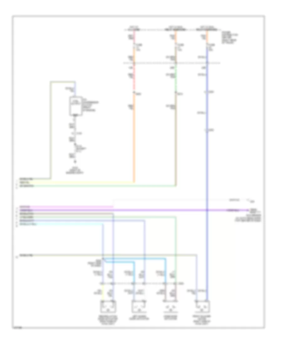
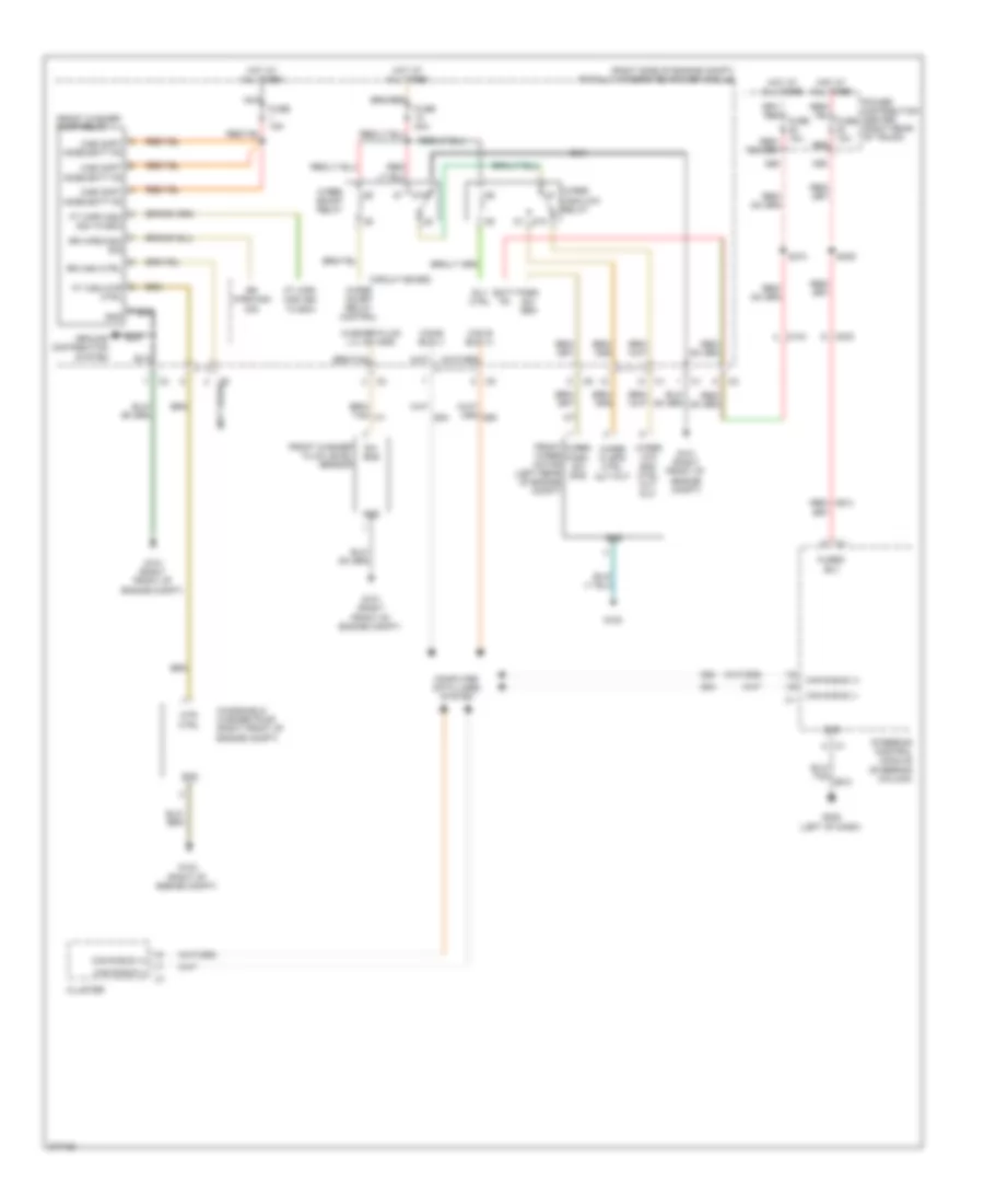
AIR CONDITIONING
Manual A/C Wiring Diagram (1 of 2) for Dodge Challenger SE 2010
 https://portal-diagnostov.com/license.html
Automotive Electricians Portal FZCO
Automotive Electricians Portal FZCO
https://portal-diagnostov.com/license.html
https://portal-diagnostov.com/license.html
Automotive Electricians Portal FZCO
Automotive Electricians Portal FZCO
List of elements for Manual A/C Wiring Diagram (1 of 2) for Dodge Challenger SE 2010:
- (left side of dash) g200
- (right side of engine compt) totally integrated power module
- 3.5l
- 5 volt sply
- 5v sply
- 87a
- A/c cltch ctrl
- A/c cltch ctrl out
- A/c press sens gnd
- A/c pressure trans- ducer sig
- A/c pressure transducer (left rear of engine compt)
- A23
- Aat sig
- Ambient air temperature sensor (right front of engine compt)
- Auto hdlp sig
- Bus (+)
- Bus (-)
- C100
- C115
- C121
- C13
- C18
- C202
- C21
- C32
- C34
- C35
- C61
- C70
- C71
- C72
- C73
- C918
- Can b bus (+)
- Can b bus (-)
- Can c
- Circuit board
- Cltch
- Cluster
- Comm dr drv
- Computer data lines system
- Ctrl
- Ctrl feed
- D54
- D55
- D64
- D65
- Defogger system
- Drv blend dr
- Ect sig
- Engine controls system
- Engine coolant temperature sensor (5.7l & 6.1l: left front of engine)
- Evaporator temperature sensor (center of hvac unit)
- Except 3.5l
- F500
- F891
- Front a/c heater module
- Front blower motor resistor block (center hvac unit)
- Frt blower hi drv
- Frt blower low drv
- Frt blower m1 drv
- Frt blower m2 drv
- Ft blower high drv
- Ft blower low drv
- Ft blower m1 drv
- Ft blower m2 drv
- Fused b (+) (i.o.d)
- Fused b(+)
- Fused run rly out
- G101 (right front of engine compt)
- G102 (right of engine compt)
- G200 (left side of dash, near breakout for ignition switch)
- G31
- G931
- G939
- Gnd
- Hi rly ctrl
- Hot at all times
- K900
- L24
- Mode dr drv
- Powertrain control module (right rear of engine compt)
- Radiator fan
- Radiator fan high relay
- Radiator fan high/low relay
- Radiator fan relay
- Recir dr drv
- Rly ctrl
- Rly out
- S110 (3.5l: right rear of engine compt)
- S240 (near bottom of hvac unit)
- Sens gnd
- Sens sig
- Sig
- Sun sens rtn
- Z908
- Z909
Manual A/C Wiring Diagram (2 of 2) for Dodge Challenger SE 2010
List of elements for Manual A/C Wiring Diagram (2 of 2) for Dodge Challenger SE 2010:
- 14b
- 28b
- 42b
- A/c compressor clutch (front of engine)
- C100
- C200
- C202
- Ctrl output
- Front blower motor (right side of hvac unit)
- Fuse 10a
- Fuse 30a
- G102 (right of engine compt)
- Gnd
- Hot at all times
- Hot w/ run relay energized
- Left blend door actuator
- Mode door actuator
- Power distribution center (right rear of trunk)
- Recirculation door actuator (right side of hvac unit)
- Rtn
- S115 (except 6.1l)
- S200
- S210
- S238 (right side of dash)
- Sens
- Sig
- Sun sensor (w/ auto headlamps) (top center of dash)
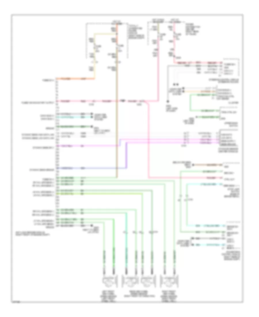
ANTI-LOCK BRAKES
Anti-lock Brakes Wiring Diagram for Dodge Challenger SE 2010
List of elements for Anti-lock Brakes Wiring Diagram for Dodge Challenger SE 2010:
- (below driver's seat) g300
- (next to deck lid latch)
- (right front of cargo pan)
- 29b
- 30a
- 30b
- 50a
- A107
- A111
- A913
- Anti-lock brakes module (right front of engine compt)
- B15
- B16
- Brake sw sig 1
- Brake sw sig 2
- Brk sig 1
- Brk sig 2
- C102
- C104
- C203
- Can b bus (+)
- Can b bus (-)
- Can c (+)
- Can c (-)
- Can c bus (+)
- Can c bus (-)
- Cluster
- Computer data lines system
- Ctrl out
- D464
- D465
- D64
- D65
- Dynamic sens ground
- Dynamic sens high data link
- Dynamic sens low data link
- Dynamic sens sply
- Dynamics sensor (center console)
- F202
- Fuse
- Fuse 10a
- Fused b (+)
- Fused b(+)
- Fused ign run-start output
- G202 (left side of dash)
- G304
- G304 (next to deck lid latch)
- G94
- Gnd
- Ground
- High data
- Hot at all times
- Hot in run or start
- Left front abs wheel speed sensor (left front wheel well)
- Lf whl spd sens(+)
- Lf whl spd sens(-)
- Low data
- Lr whl spd sens (+)
- Lr whl spd sens (-)
- Nca
- Power distribution center (right rear of trunk)
- Powertrain control module (right rear of engine compt)
- Rear abs wheel speed sensor
- Red
- Rf whl spd sens (+)
- Rf whl spd sens (-)
- Right front abs wheel speed sensor (right front wheel well)
- Rr whl spd sens (+)
- Rr whl spd sens (-)
- S209
- S309
- Sens ground
- Steering control module (steering column)
- Stop lamp switch (base of brake pedal)
- Tan/ red
- Tan/red
- Totally integrated power module (right side of engine compt)
- Trac ctrl sw
- Traction ctrl sw sense
- Upper bank switch
- Z910
- Z931
ANTI-THEFT
Anti-theft Wiring Diagram for Dodge Challenger SE 2010
List of elements for Anti-theft Wiring Diagram for Dodge Challenger SE 2010:
- (below passenger's seat) g301
- (left side of dash) g202
- (next to deck lid latch) g304
- 17b
- A106
- Ajar sw sns
- Antenna 2 rtn
- Antenna 2 sig
- Antenna 3 rtn
- Antenna 3 sig
- C200
- C203
- C300
- C301
- Can b bus(+)
- Can b bus(+) c1
- Can b bus(-)
- Cargo lamp
- Circuit board
- Cluster
- Com-lin tp mntr lan
- Computer data lines system
- D508
- D54
- D55
- D922
- D923
- D924
- D925
- Decklid door latch
- Decklid release switch
- Dl/lg ajar sw
- Dl/lg rel sw sns
- Dl/lg release
- Driver door latch
- Driver door module
- Drv dr 2nd ajar sw sns
- Drv dr ajar sw sns
- Fuse 15a red
- Fuse 20a red
- Fused b(+)
- G102 (right of engine compt)
- G202 (left side of dash)
- G300 (below driver's seat)
- G301 (below passenger's seat)
- G70
- G74
- G745
- G75
- G755
- Gnd
- Ground
- Hood ajar sw sense
- Hood ajar switch (right side of engine compt)
- Hot at all times red
- Pass dr 2nd ajar sw sns
- Pass dr ajar sw sns
- Passenger door latch
- Passenger door module
- Passive entry 2 antenna
- Passive entry 3 antenna
- Passive entry module (right side of dash)
- Power distribution center (right rear of trunk)
- Red/tan
- Release drv
- S215
- S355
- S360
- Totally integrated power module (right side of engine compt)
- Wireless ignition node
- Z910
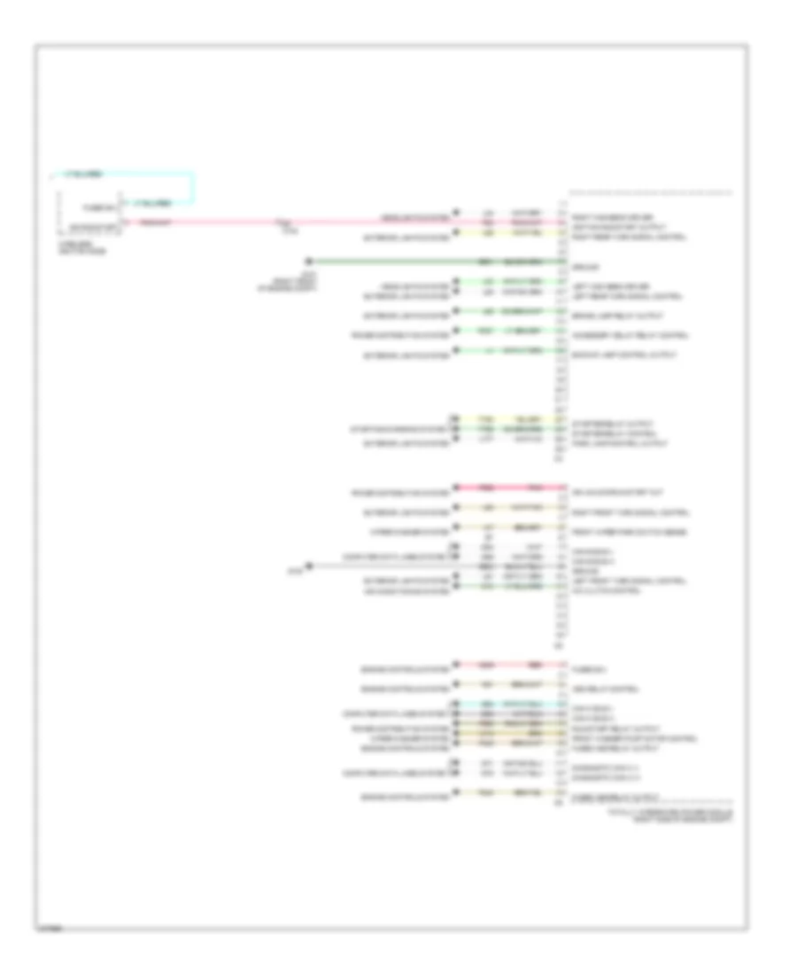
BODY CONTROL MODULES
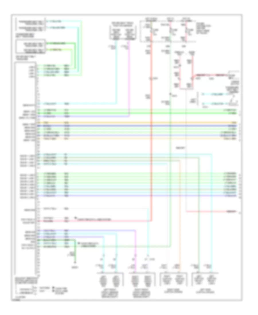
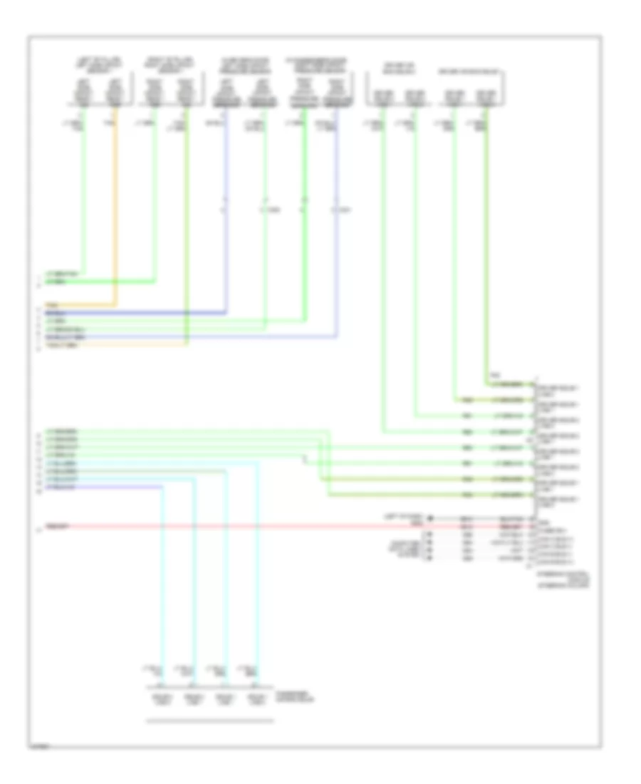
Body Control Modules Wiring Diagram (1 of 2) for Dodge Challenger SE 2010
List of elements for Body Control Modules Wiring Diagram (1 of 2) for Dodge Challenger SE 2010:
- (right front of engine compt) g101
- 38b
- A/c clutch control output
- A/c pressure sensor ground
- A/c pressure transducer signal
- A107
- A11
- A111
- A117
- A22
- Aat signal
- Air conditioning system
- Anti-lock brakes system
- Anti-theft system
- B(+)
- B20
- Battery
- Brake fluid level sig
- C104
- C18
- C918
- Cooling fans system
- Exterior lights system
- F891
- F923
- Front wiper high/low relay high speed output
- Front wiper high/low relay low speed output
- Fuse 10a
- Fuse 40a
- Fused b(+)
- Fused b(+) (i.o.d.)
- Fused b(+) (pump)
- Fused b(+) (valve)
- G31
- G70
- G931
- Ground
- Hazard switch sense
- Headlights system
- Hood ajar switch sense
- Horn control output
- Horns system
- Hot at all times
- Instrument cluster system
- L43
- L44
- L89
- L91
- Left fog lamp control output
- Left low beam driver
- Lo spd rad fan ctrl
- N210
- N23
- N24
- Nca
- Pass through post
- Power distribution center (right rear of trunk)
- Power distribution system
- Rad fan control relay output
- Rad fan high/low control feed
- Red
- Right low beam driver
- Run relay control
- S138
- S215
- S374
- Sensor ground
- Tan/red
- Totally integrated power module (right side of engine compt)
- Washer fluid level switch sense
- Wiper/washer system
- Z901
Body Control Modules Wiring Diagram (2 of 2) for Dodge Challenger SE 2010
List of elements for Body Control Modules Wiring Diagram (2 of 2) for Dodge Challenger SE 2010:
- A/c clutch control
- A209
- Accessory delay relay control
- Air conditioning system
- Asd relay control
- Backup lamp control output
- Brake lamp relay output
- C102
- C13
- Can b bus (+)
- Can b bus (-)
- Can c bus (+)
- Can c bus (-)
- Computer data lines system
- D54
- D55
- D64
- D65
- D71
- D72
- Diagnostic can c (+)
- Diagnostic can c (-)
- Engine controls system
- Exterior lights system
- F20
- F342
- F343
- F902
- F950
- Front washer pump motor control
- Front wiper park switch sense
- Fused asd relay output
- Fused b(+)
- G100
- G101 (right front of engine compt)
- Ground
- Headlights system
- Ign run-start
- Ign unlock-run-start out
- Ignition run-start output
- K51
- L33
- L34
- L53
- L60
- L61
- L62
- L63
- L777
- Left front turn signal control
- Left high beam driver
- Left rear turn signal control
- P307
- Park lamp control output
- Pnk
- Power distribution system
- Red
- Right front turn signal control
- Right high beam driver
- Right rear turn signal control
- Run/start relay output
- Starter relay control
- Starter relay output
- Starting/charging system
- T750
- T752
- Totally integrated power module (right side of engine compt)
- W10
- Wiper/washer system
- Wireless ignition node
- Z901
- Z902
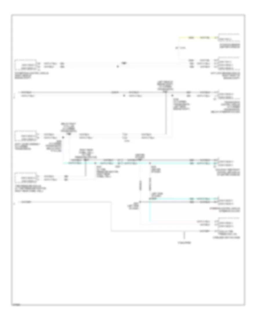
COMPUTER DATA LINES
Computer Data Lines Wiring Diagram (1 of 2) for Dodge Challenger SE 2010
List of elements for Computer Data Lines Wiring Diagram (1 of 2) for Dodge Challenger SE 2010:
- (below right "a" pillar) s318
- (left side of dash) s218
- (right side of dash) s204
- 38b
- A106
- C102
- C104
- C203
- C204
- C300
- C301
- C311
- Can b bus (+)
- Can b bus (-)
- Can c bus (+)
- Can c bus (-)
- Circuit board
- Cluster
- Com-lin tpm lan
- D508
- D54
- D55
- D64
- D65
- D71
- D72
- Data link connector (left side of dash, above pedals)
- Diagnostic can c (+)
- Diagnostic can c (-)
- Driver door module
- Electronic overhead module (if equipped) (overhead console)
- Front a/c heater module
- Fuse 10a
- Fuse 15a
- Fused b (+)
- G202 (left side of dash)
- Hands free module (except navigation) (right side of dash)
- Heated seats module (if equipped)
- Hot at all times
- Passenger door module
- Passive entry module (if equipped) (right side of dash)
- Power distribution center (right rear of trunk)
- Radio
- Radio amplifier (if equipped) (left of dash)
- Red
- S205 (right side of dash)
- S215
- S219 (center of dash)
- S319 (below right "a" pillar)
- S374
- Steering control module (steering column)
- Sunroof motor/module (if equipped) (rear center of headliner)
- Totally integrated power module (right side of engine compt)
- Z910
Computer Data Lines Wiring Diagram (2 of 2) for Dodge Challenger SE 2010
List of elements for Computer Data Lines Wiring Diagram (2 of 2) for Dodge Challenger SE 2010:
- (below right "a" pillar) (w/ 5 speed transmission) s391
- (center of dash) s237
- (left rear of engine compt) (w/ 5 speed transmission) s171
- (left side of dash) s206
- (right rear wheel well) (w/ tire pressure monitor) s336
- Anti-lock brakes module (right front of engine compt)
- C104
- C200
- Can c bus (+)
- Can c bus (-)
- Can yaw (-)
- Com-lin tire press moni lan
- D464
- D64
- D65
- Dynamics sensor (center console)
- If equipped
- Occupant restraint controller module (in center console)
- Powertrain control module (right rear of engine compt)
- S122
- S124
- S169 (w/ 5 speed transmission) (left rear engine compt)
- S207 (left side of dash)
- S235 (center of dash)
- S337 (w/ tire pressure monitor) (right rear wheel well)
- S390 (w/ 5 speed transmission) (below right "a" pillar)
- Shift lever assembly (w/ 5 speed transmission)
- Steering control module (steering column)
- Tire pressure module (w/ tire pressure monitor) (right rear wheel well)
- Transmission control module (w/ 5 speed transmission) (below steering column)
- Wireless ignition node
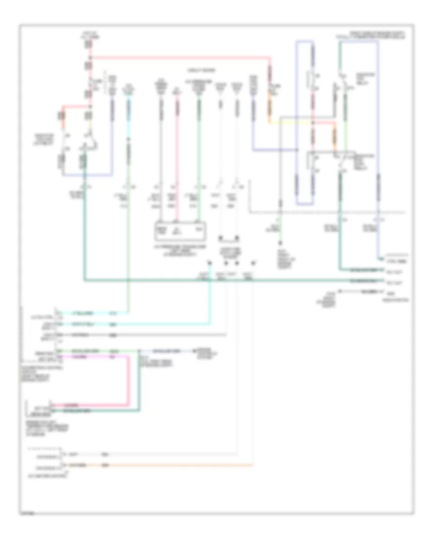
COOLING FAN
Cooling Fan Wiring Diagram for Dodge Challenger SE 2010
List of elements for Cooling Fan Wiring Diagram for Dodge Challenger SE 2010:
- (right side of engine compt) totally integrated power module
- 5v sply
- 87a
- A/c cltch ctrl
- A/c heater control
- A/c press sens gnd
- A/c pressure trans- ducer sig
- A/c pressure transducer (left rear of engine compt)
- Bus (+)
- Bus (-)
- C13
- C18
- C918
- Can b bus (+)
- Can b bus (-)
- Can c
- Circuit board
- Cltch ctrl
- Computer data lines system
- Ctrl feed
- D54
- D55
- D64
- D65
- Ect sig
- Engine controls system
- Engine coolant temperature sensor (5.7l & 6.1l: left front of engine)
- F891
- Fuse 40a
- Fuse 50a
- G101 (right front of engine compt)
- G102 (right of engine compt)
- Gnd
- Hot at all times
- K915
- Powertrain control module (right rear of engine compt)
- Rad fan hi spd sig
- Rad fan mtr spd sig
- Radiator fan
- Radiator fan high relay
- Radiator fan high/ low relay
- Radiator fan relay
- Rly out
- S110 (3.5l: right rear of engine compt)
- Sens gnd
- Sig
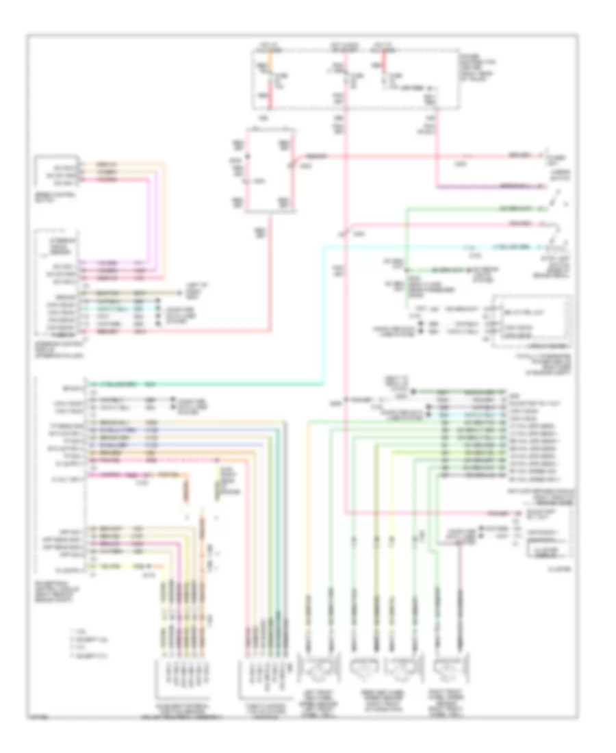
CRUISE CONTROL
Cruise Control Wiring Diagram for Dodge Challenger SE 2010
List of elements for Cruise Control Wiring Diagram for Dodge Challenger SE 2010:
- (left of dash) g202
- (next to deck lid latch)
- 19b
- 29b
- 3.5l
- 30b
- 5 volt sply
- 5.7l
- 5v sply
- A913
- Accelerator pedal position sensor (adjustable pedal assembly)
- Antilock brakes module (right front of engine compt)
- App gnd 1
- App gnd 2
- App sens gnd 1
- App sens gnd 2
- App sig 1
- App sig 2
- B16
- Br lp ctrl out
- Br sig 2
- C100
- C102
- C104
- C203
- C300
- Can b bus +
- Can b bus -
- Can b bus+
- Can b bus-
- Can c bus+
- Can c bus-
- Circuit board
- Cluster
- Cluster display
- Computer data lines system
- D54
- D55
- D64
- D65
- Etc motor (+)
- Etc motor (-)
- Etc mtr (+)
- Etc mtr (-)
- Except 3.5l
- Except 5.7l
- Exterior lights system
- F202
- F852
- F855
- F856
- Fuse 10a
- Fuse 5a
- Fused b(+)
- Fused b+
- G304
- Gnd
- Ground
- Hot at all times
- Hot in run or start
- K122
- K124
- K126
- K167
- K22
- K23
- K29
- K400
- K922
- L53
- Left front abs wheel speed sensor (left front wheel well)
- Lf whl spd sens +
- Lf whl spd sens -
- Lr whl spd sens +
- Lr whl spd sens -
- Mirror switch
- Nca
- Power distribution center (right rear of trunk)
- Powertrain control module (right rear of engine compt)
- Rear abs wheel speed sensor (right front of cargo pan)
- Red
- Rf whl speed sig
- Rf whl speed sply
- Right front wheel speed sensor (right front wheel well)
- Rr whl spd sens +
- Rr whl spd sens -
- Run/start rly out
- S/c sig 1
- S/c sig 2
- S/c sw gnd
- S105 (right rear of engine)
- S175
- S209
- S302 (body floor, near passenger door)
- S309
- Speed control switch
- Steering angle sensor
- Steering control module (steering column)
- Stop lamp switch (base of brake pedal)
- Throttle body (top of intake manifold)
- Totally integrated power module (right side of engine compt)
- Tp sens gnd
- Tp sig 1
- Tp sig 2
- V71
- V72
- V937
- Z910
- Z931
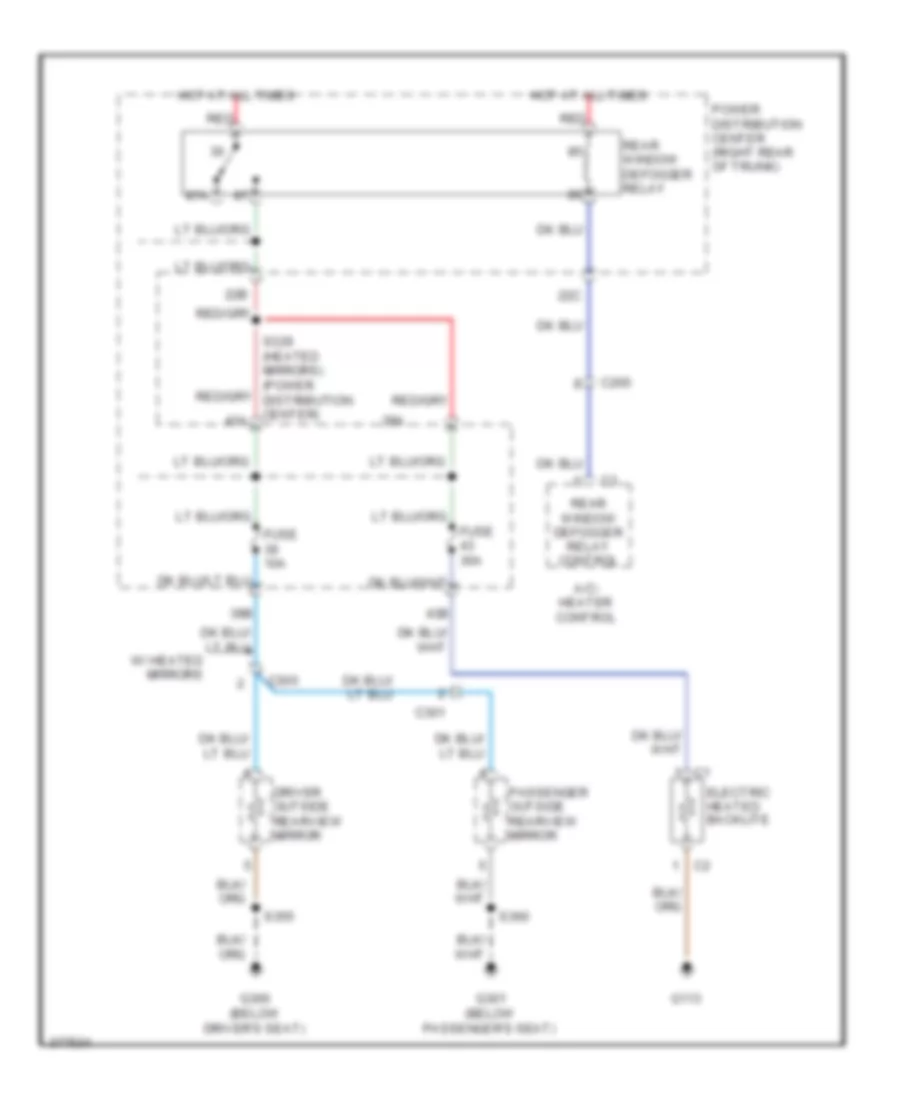
DEFOGGERS
Defoggers Wiring Diagram for Dodge Challenger SE 2010
List of elements for Defoggers Wiring Diagram for Dodge Challenger SE 2010:
- 22b
- 22c
- 39a
- 39b
- 43a
- 43b
- 87a
- A/c- heater control
- C200
- C300
- C301
- Driver outside rearview mirror
- Electric heated backlite
- Fuse 10a
- Fuse 30a
- G113
- G300 (below driver's seat)
- G301 (below passenger's seat)
- Hot at all times
- Passenger outside rearview mirror
- Power distribution center (right rear of trunk)
- Rear window defogger relay
- Rear window defogger relay control
- Red
- S355
- S360
- W/ heated mirrors
ENGINE PERFORMANCE
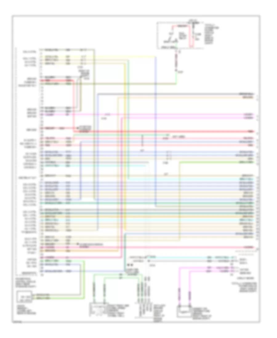
3.5L
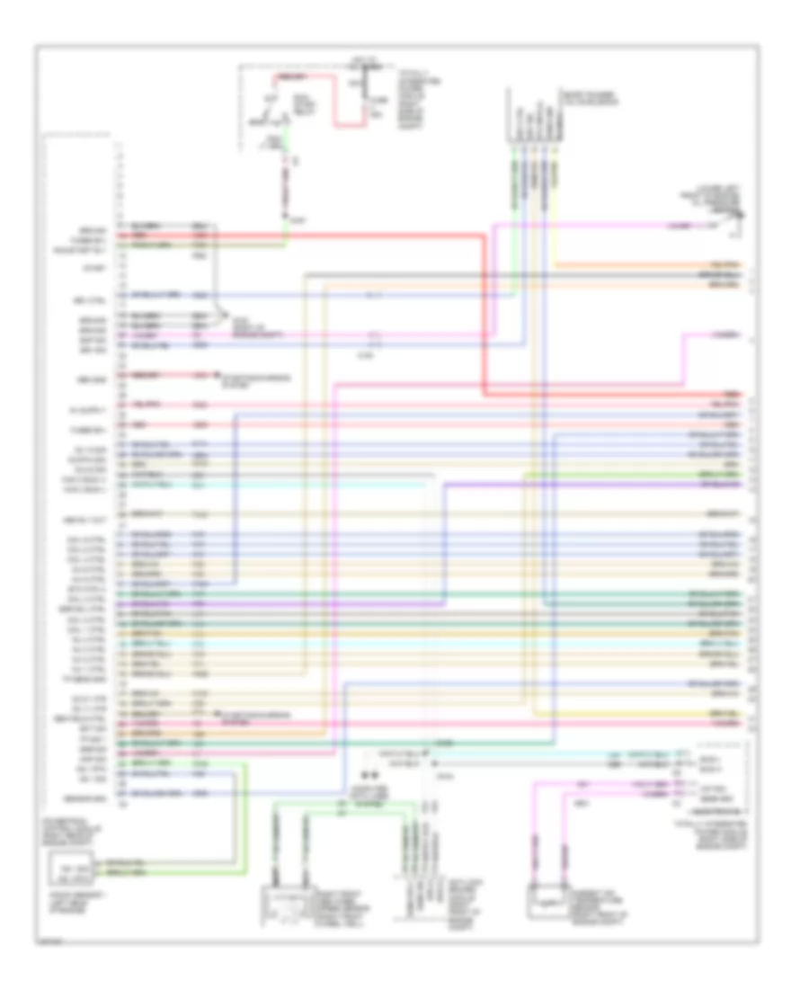
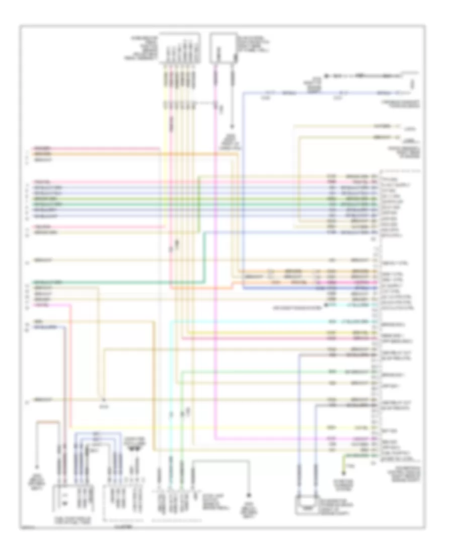
3.5L, Engine Performance Wiring Diagram (1 of 4) for Dodge Challenger SE 2010
List of elements for 3.5L, Engine Performance Wiring Diagram (1 of 4) for Dodge Challenger SE 2010:
- (lower left front of engine) oil pressure switch
- 5v sply
- 87a
- A209
- A804
- Aat sig
- Ambient air temperature sensor (right front of engine compt)
- Anti-lock brakes module (right front of engine compt)
- Asd rly out
- Bus (+)
- Bus (-)
- C100
- Can c bus (+)
- Can c bus (-)
- Coil 1 ctrl
- Coil 2 ctrl
- Coil 3 ctrl
- Coil 4 ctrl
- Coil 5 ctrl
- Coil 6 ctrl
- Computer data lines system
- D64
- D65
- Ect sig
- Egr sig
- Egr sol ctrl
- Electronics
- Eop sig
- Etc mtr (+)
- F342
- F856
- F902
- F950
- Fuse 25a
- Fused b(+)
- G102 (right of engine compt)
- G31
- G931
- Gen field ctrl
- Gen sns
- Ground
- Hot at all times
- Inj 1 ctrl
- Inj 2 ctrl
- Inj 3 ctrl
- Inj 4 ctrl
- Inj 5 ctrl
- Inj 6 ctrl
- K10
- K11
- K12
- K124
- K13
- K14
- K141
- K15
- K16
- K17
- K18
- K19
- K199
- K20
- K22
- K235
- K236
- K243
- K34
- K35
- K38
- K42
- K58
- K900
- K904
- K922
- K942
- K99
- Knock sensor 1 (left rear of engine)
- Ks 1 rtn
- Ks 1 sig
- Map sig
- Nca
- O2 1/1 htr
- O2 1/2 sig
- O2 2/1 htr
- O2 2/2 sig
- O2 rtn (dn)
- Powertrain control module (right rear of engine compt)
- Red
- Right front abs wheel speed sensor (right front wheel well)
- Run/ start relay
- Run/start rly
- S122
- S124
- S167
- Sens gnd
- Sens sig
- Sens sply
- Sensor gnd
- Short runner valve solenoid
- Srv ctrl
- Srv sig
- Start
- Starting/charging system
- Totally integrated power module (right side of engine compt)
- Tp sens gnd
- Tp sig 1
- Z904
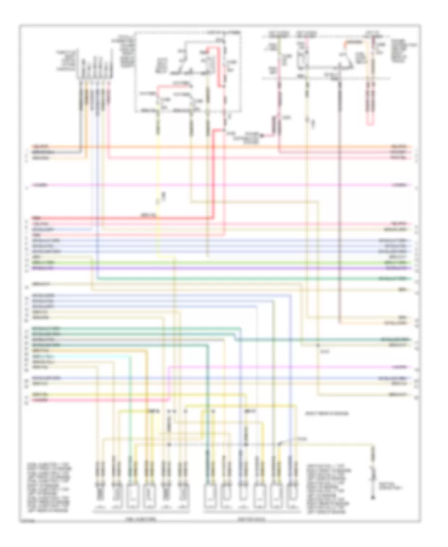
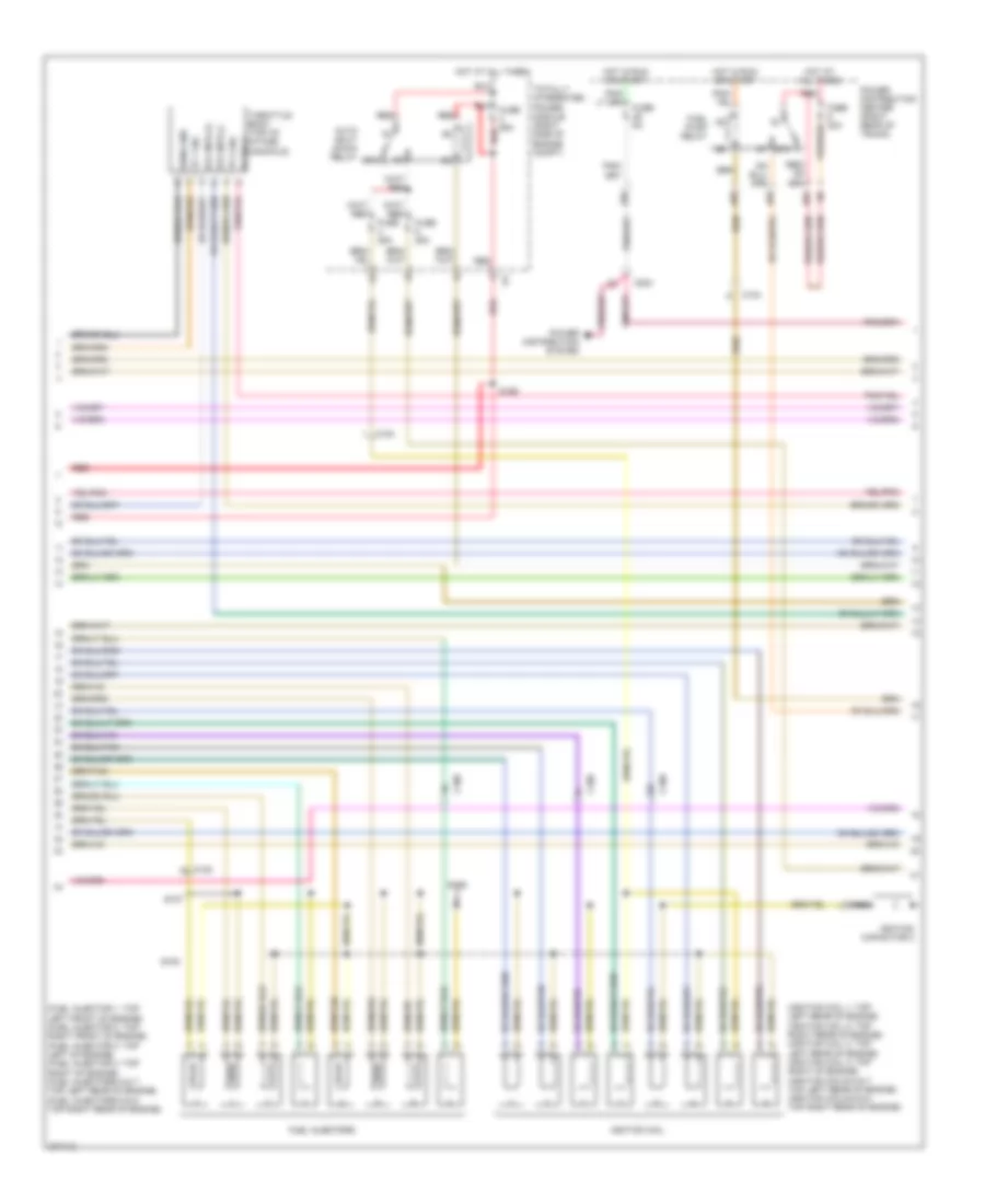
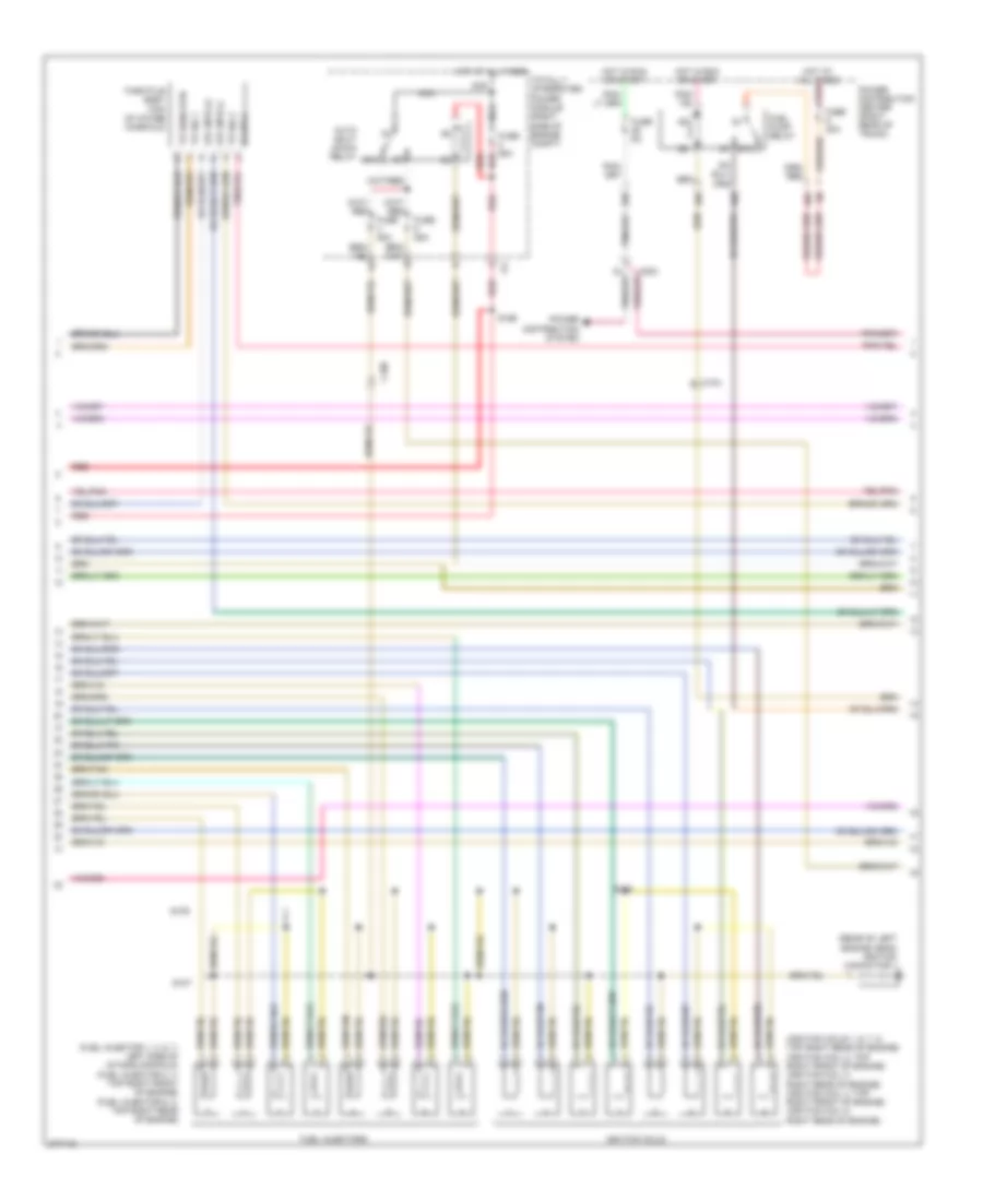
3.5L, Engine Performance Wiring Diagram (2 of 4) for Dodge Challenger SE 2010
List of elements for 3.5L, Engine Performance Wiring Diagram (2 of 4) for Dodge Challenger SE 2010:
- (fuel injector 1: top right front of engine) (fuel injector 2: top left front of engine) (fuel injector 3: top right of engine) (fuel injector 4: top left of engine) (fuel injector 5: top right rear of engine) (fuel injector 6: top left rear of engine)
- (ignition coil 1: top right front of engine) (ignition coil 2: top left side of engine) (ignition coil 3: top right of engine) (ignition coil 4: top left of engine) (ignition coil 5: top right rear of engine) (ignition coil 6: top left side of engine)
- (right rear of engine)
- 29b
- 46a
- 46b
- 46d
- 5v sply
- 87a
- Auto shut down relay
- C100
- C104
- C203
- Etc mtr (+)
- Etc mtr (-)
- Fuel injectors
- Fuel pump relay
- Fuse 20a
- Fuse 25a
- Fuse 5a
- Hot at all times
- Hot at all times red
- Hot in run or start
- Ignition capacitor 1
- Ignition coils
- Nca
- Power distribution center (right rear of trunk)
- Power distribution system
- Red
- S107
- S108
- S109
- S143
- S166
- Sens gnd
- Throttle body (top of intake manifold)
- Totally integrated power module (right side of engine compt)
- Tp sig 1
- Tp sig 2
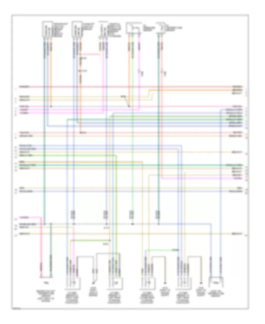
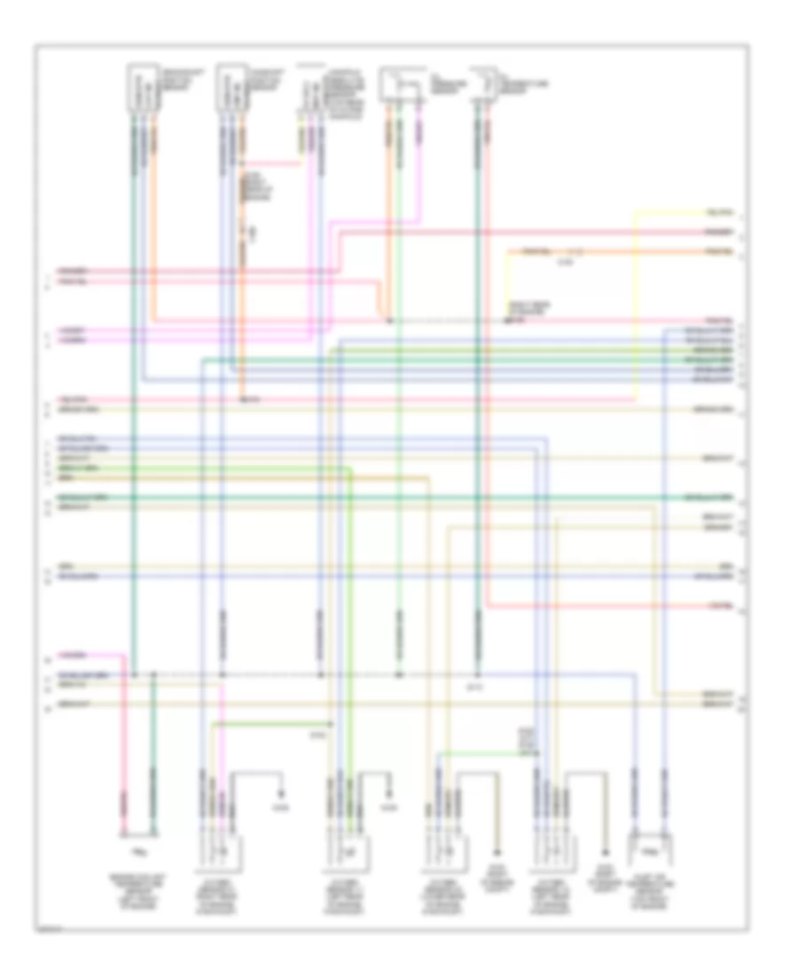
3.5L, Engine Performance Wiring Diagram (3 of 4) for Dodge Challenger SE 2010
List of elements for 3.5L, Engine Performance Wiring Diagram (3 of 4) for Dodge Challenger SE 2010:
- 5v sply
- C100
- Camshaft position sensor
- Ckp sig
- Cmp sig
- Crankshaft position sensor (right rear of engine)
- Engine coolant temperature sensor
- Exhaust gas recirculation valve assembly (rear of engine)
- G102 (right of engine compt)
- G109 (right side of engine)
- Inlet air temperature sensor (top of engine)
- Manifold absolute pressure sensor (top of engine) 5v sply
- Map sig
- Oxygen sensor 1/1 (right rear of engine, in exhaust)
- Oxygen sensor 1/2 (left rear of engine, in exhaust)
- Oxygen sensor 2/1 (left side of engine, in exhaust)
- Oxygen sensor 2/2 (lower rear of engine, in exhaust)
- S105
- S110 (right rear of engine compt)
- S125
- S153
- S154
- S175
- Sens gnd
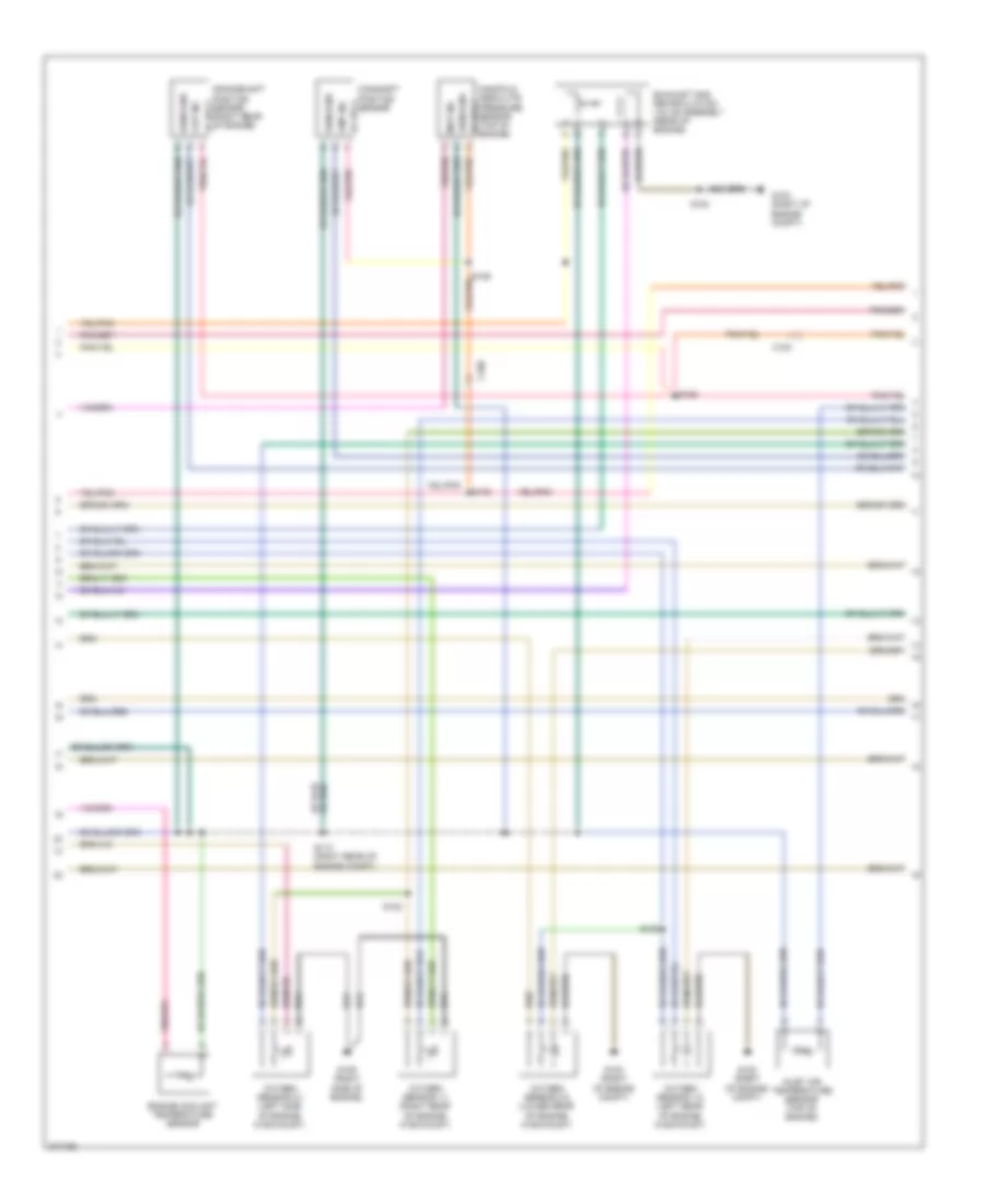
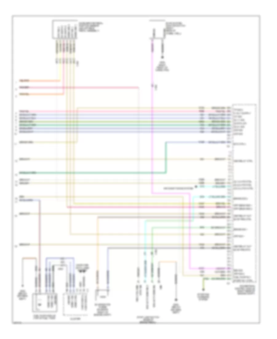
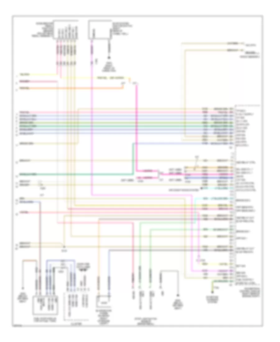
3.5L, Engine Performance Wiring Diagram (4 of 4) for Dodge Challenger SE 2010
List of elements for 3.5L, Engine Performance Wiring Diagram (4 of 4) for Dodge Challenger SE 2010:
- A/c clutch ctrl
- Accelerator pedal position sensor (adjustable pedal assembly)
- Air conditioning system
- App sens gnd 1
- App sens gnd 2
- App sig 1
- App sig 2
- Asd relay ctrl
- Asd relay out
- B15
- B16
- Brake sig 1
- Brake sig 2
- Brk actv sens sig
- Brk actv sens sig 2
- C104
- C13
- C203
- Can b bus (+)
- Can b bus (-)
- Ckp sig
- Cluster
- Cmp sig
- Computer data lines system
- Eng ctrl run/
- Esm sig
- Etc mtr (-)
- Evap prg ctrl
- Evap prg rtn
- Evap system monitor switch (right rear of wheel well)
- Evaporator purge solenoid (right of engine compt)
- F342
- F855
- Fuel pump module (top of fuel tank)
- Fuel pump rly
- G300 (below driver's seat)
- G302 (right front of cargo pan)
- Gnd
- Ground
- Iat sig
- K107
- K122
- K126
- K167
- K21
- K23
- K24
- K29
- K299
- K31
- K399
- K400
- K41
- K43
- K44
- K51
- K52
- K70
- K902
- O2 1/1 sig
- O2 1/2 htr ctrl
- O2 2/1 sig
- O2 2/2 htr ctrl
- O2 rtn (up)
- Powertrain control module (right rear of engine compt)
- Sens 1 sig
- Sens 2 sig
- Sens gnd 1
- Sens gnd 2
- Start rly ctrl
- Starting/ charging system
- Stop lamp switch (base of brake pedal)
- Strt ign
- T752
- Tp sig 2
- Z210
- Z912
5.7L
5.7L, Engine Performance Wiring Diagram (1 of 4) for Dodge Challenger SE 2010
List of elements for 5.7L, Engine Performance Wiring Diagram (1 of 4) for Dodge Challenger SE 2010:
- 87a
- A209
- A804
- Aat sig
- Ambient air temperature sensor (right front of engine compt)
- Anti-lock brakes module (right front of engine compt)
- Asd relay out
- Bus (+)
- Bus (-)
- C100
- C101
- Can c bus (+)
- Can c bus (-)
- Coil 1 ctrl
- Coil 2 ctrl
- Coil 3 ctrl
- Coil 4 ctrl
- Coil 5 ctrl
- Coil 6 ctrl
- Coil 7 ctrl
- Coil 8 ctrl
- Computer data lines system
- D64
- D65
- Ect sig
- Electronics
- Eop sig
- Etc mtr (+)
- F342
- F856
- F950
- Fuse 25a
- Fused b(+)
- G102 (right of engine compt)
- G31
- G931
- Gen field ctrl
- Gen sns
- Ground
- Hot at all times
- Inj 1 ctrl
- Inj 2 ctrl
- Inj 3 ctrl
- Inj 4 ctrl
- Inj 5 ctrl
- Inj 6 ctrl
- Inj 7 ctrl
- Inj 8 ctrl
- K10
- K11
- K12
- K124
- K13
- K14
- K141
- K15
- K16
- K17
- K18
- K19
- K199
- K20
- K22
- K243
- K26
- K28
- K38
- K42
- K452
- K453
- K58
- K900
- K904
- K922
- K942
- K97
- K98
- K99
- Knock sensor 1 (rear of engine)
- Ks 1 rtn
- Ks 1 sig
- Map sig
- Mds 4 ctrl
- Mds 6 ctrl
- Multi displacement system solenoids
- Nca
- O2 1/1 htr
- O2 1/2 sig
- O2 2/1 htr
- O2 2/2 sig
- O2 rtn (dn)
- Powertrain control module (right rear of engine compt)
- Red
- Right front abs wheel speed sensor (right front wheel well)
- Run/ start relay
- Run/start rly
- S122
- S124
- S167
- S270
- Sens gnd
- Sensor gnd
- Sig
- Sply
- Starting/ charging system
- Starting/charging system
- Totally integrated power module (right side of engine compt)
- Tp 1 sig
- Tp sens gnd
- Z904
5.7L, Engine Performance Wiring Diagram (2 of 4) for Dodge Challenger SE 2010
List of elements for 5.7L, Engine Performance Wiring Diagram (2 of 4) for Dodge Challenger SE 2010:
- (fuel injector 1: top left front of engine) (fuel injector 2: top right front of engine) (fuel injector 3: top left of engine) (fuel injector 4: top right of engine) (fuel injectors 5 & 7: top left rear of engine) (fuel injectors 6 & 8: top right rear of engine)
- (ignition coil 1: top left rear of engine) (ignition coil 2: top right rear of engine) (ignition coil 3: top left rear of engine) (ignition coil 4: top right of engine) (ignition coils 5 & 7: top left rear of engine) (ignition coils 6 & 8: top right rear of engine)
- 29b
- 46a
- 46b
- 46d
- 5v sply
- 87a
- Auto shut down relay
- C100
- C104
- C203
- Etc mtr (+)
- Etc mtr (-)
- Fuel injectors
- Fuel pump relay
- Fuse 20a
- Fuse 25a
- Fuse 5a
- Hot at all times
- Hot in run or start
- Ignition capacitor 2
- Ignition coil
- Nca
- Power distribution center (right rear of trunk)
- Power distribution system
- Red
- S107
- S108
- S109
- S166
- Sens gnd
- Throttle body (top of intake manifold)
- Totally integrated power module (right side of engine compt)
- Tp 1 sig
- Tp 2 sig
5.7L, Engine Performance Wiring Diagram (3 of 4) for Dodge Challenger SE 2010
List of elements for 5.7L, Engine Performance Wiring Diagram (3 of 4) for Dodge Challenger SE 2010:
- 5v sply
- C100
- Camshaft position sensor
- Ckp sig
- Cmp sig
- Crankshaft position sensor (right rear of engine) 5v sply
- Engine coolant temperature sensor (left front of engine)
- G102 (right of engine compt)
- G109 (right side of engine)
- Inlet air temperature sensor
- Manifold absolute pressure sensor (top of engine) sens gnd
- Map sig
- Oil pressure sensor
- Oil temperature sensor
- Oxygen sensor 1/1 (left rear of engine, in exhaust)
- Oxygen sensor 1/2 (left rear of engine, in exhaust)
- Oxygen sensor 2/1 (right side of engine, in exhaust)
- Oxygen sensor 2/2 (lower rear of engine, in exhaust)
- S105
- S110
- S125
- S152
- S175
- Sens gnd
5.7L, Engine Performance Wiring Diagram (4 of 4) for Dodge Challenger SE 2010
List of elements for 5.7L, Engine Performance Wiring Diagram (4 of 4) for Dodge Challenger SE 2010:
- 2 rtn
- 2 sig
- 5v sply
- A/c clutch ctrl
- Accelerator pedal position sensor (adjustable pedal assembly)
- Air conditioning system
- App sens gnd 2
- App sig 1
- App sig 2
- Asd relay out
- Asd rly ctrl
- B15
- B16
- Brake sig 1
- Brake sig 2
- C100
- C101
- C104
- C13
- C203
- Can b bus (+)
- Can b bus (-)
- Ckp sig
- Cluster
- Cmp sig
- Computer data lines system
- Eot sig
- Esm sig
- Etc mtr (-)
- Evap prg ctrl
- Evap prg rtn
- Evap system monitor switch (right rear of wheel well)
- Evaporator purge solenoid (right of engine compt)
- F342
- F855
- Fuel pump module (top of fuel tank)
- Fuel pump rly
- G102 (right of engine compt)
- G224
- G300 (below driver's seat)
- G302 (right front of cargo pan)
- Gnd
- Ground
- Iat sig
- K107
- K122
- K126
- K167
- K21
- K23
- K24
- K242
- K29
- K299
- K31
- K399
- K400
- K41
- K43
- K44
- K442
- K451
- K454
- K51
- K52
- K70
- K852
- K902
- K924
- Knock sensor 2 (right rear of engine)
- Ks 2 rtn
- Ks 2 sig
- Mds 1 ctrl
- Mds 7 ctrl
- O2 1/1 sig
- O2 1/2 htr ctrl
- O2 2/1 sig
- O2 2/2 htr ctrl
- O2 rtn (up)
- Powertrain control module (right rear of engine compt)
- Run/start eng ctrl
- S143
- S270
- Sens 1 sig
- Sens 2 sig
- Sens gnd 1
- Sens gnd 2
- Sens sig 2 brk actv
- Sens sig brk actv
- Start rly ctrl
- Starting/ charging system
- Stop lamp switch (base of brake pedal)
- T752
- Tp 2 sig
- Variable camshaft timing solenoid
- Vct ctrl
- Z210
- Z912
6.1L
6.1L, Engine Performance Wiring Diagram (1 of 4) for Dodge Challenger SE 2010
List of elements for 6.1L, Engine Performance Wiring Diagram (1 of 4) for Dodge Challenger SE 2010:
- (not used)
- (right of engine compt) g102
- 87a
- A/t
- A209
- A804
- Aat sig
- Altr fld fd
- Ambient air temperature sensor (right front of engine compt)
- Anti-lock brakes module (right front of engine compt)
- Asd relay out
- Bus (+)
- Bus (-)
- C100
- Can bus (+)
- Can bus (-)
- Circuit board
- Coil 1 ctrl
- Coil 2 ctrl
- Coil 3 ctrl
- Coil 4 ctrl
- Coil 5 ctrl
- Coil 6 ctrl
- Coil 7 ctrl
- Coil 8 ctrl
- Computer data lines system
- D64
- D65
- Ect sig
- Eop sig
- Etc mtr (+)
- F342
- F856
- F950
- Fuse 25a
- Fused b(+)
- G31
- G931
- Gen sns
- Ground
- Hot at all times nca
- Inj 1 ctrl
- Inj 2 ctrl
- Inj 3 ctrl
- Inj 4 ctrl
- Inj 5 ctrl
- Inj 6 ctrl
- Inj 7 ctrl
- Inj 8 ctrl
- K10
- K11
- K12
- K124
- K13
- K14
- K141
- K15
- K16
- K17
- K18
- K19
- K199
- K20
- K22
- K243
- K26
- K28
- K38
- K42
- K452
- K58
- K900
- K904
- K922
- K942
- K97
- K98
- K99
- Knock sensor 1 (lower left rear of engine)
- Ks 1 rtn
- Ks 1 sig
- M/t
- Map sig
- O2 1/1 htr
- O2 1/2 sig
- O2 2/1 htr
- O2 2/2 sig
- O2 rtn (dn)
- Powertrain control module (right rear of engine compt)
- Red
- Right front abs wheel speed sensor (right front wheel well)
- Run/ start relay
- Run/start rly
- S122
- S124
- S167
- Sens gnd
- Sens sig
- Sens sply
- Sensor rtn
- Sol mds cyl 4
- Starting/ charging system
- Starting/charging system
- Totally integrated power module (right side of engine compt)
- Tp sens rtn
- Tp sig 1
- Z904
6.1L, Engine Performance Wiring Diagram (2 of 4) for Dodge Challenger SE 2010
List of elements for 6.1L, Engine Performance Wiring Diagram (2 of 4) for Dodge Challenger SE 2010:
- (fuel injector 1, 3, 5, 7: left side of intake manifold) (fuel injector 2, 4: top right front of engine) (fuel injector 6, 8: top right rear of engine)
- (ignition coils 1, 6, 7, 8: top right rear of engine) (ignition coil 2: top right front of engine) (ignition coil 3: right rear of engine) (ignition coil 4: top right front of engine) (ignition coil 5: right rear of engine)
- (rear of left engine head) ignition capacitor 1
- 29b
- 46a
- 46b
- 46d
- 5v sply
- 87a
- Auto shut down relay
- C100
- C104
- Etc mtr (+)
- Etc mtr (-)
- Fuel injectors
- Fuel pump relay
- Fuse 20a
- Fuse 25a
- Fuse 5a
- Hot at all times
- Hot at all times red
- Hot in run or start
- Ignition coils
- Nca
- Power distribution center (right rear of trunk)
- Power distribution system
- Red
- S107
- S108
- S109
- S166
- Throttle body (top of intake manifold)
- Totally integrated power module (right side of engine compt)
- Tp sens rtn
- Tp sig 1
- Tp sig 2
6.1L, Engine Performance Wiring Diagram (3 of 4) for Dodge Challenger SE 2010
List of elements for 6.1L, Engine Performance Wiring Diagram (3 of 4) for Dodge Challenger SE 2010:
- (right rear of engine) s105
- 5v sply
- C100
- Camshaft position sensor
- Ckp sig
- Cmp sig
- Crankshaft position sensor
- Engine coolant temperature sensor (left front of engine)
- G102 (right of engine compt)
- G109
- Inlet air temperature sensor (top front of engine)
- Manifold absolute pressure sensor (top rear of intake sens rtn
- Manifold)
- Map sig
- Oil pressure sensor
- Oil temperature sensor
- Oxygen sensor 1/1 (left rear of engine, in exhaust)
- Oxygen sensor 1/2 (left rear of engine, in exhaust)
- Oxygen sensor 2/1 (right rear of engine, in exhaust)
- Oxygen sensor 2/2 (lower rear of engine, in exhaust)
- S106 (right rear of engine)
- S110
- S153
- S175
- S182 (m/t) s125 (a/t)
- Sens rtn
6.1L, Engine Performance Wiring Diagram (4 of 4) for Dodge Challenger SE 2010
List of elements for 6.1L, Engine Performance Wiring Diagram (4 of 4) for Dodge Challenger SE 2010:
- (not used)
- 5v sply
- A/c clutch ctrl
- A/t
- Accelerator pedal position sensor (adjustable pedal assembly)
- Air conditioning system
- App sens gnd 2
- App sens rtn
- App sig 1
- App sig 2
- Asd relay ctrl
- Asd relay out
- B15
- B16
- Brake sig 1
- Brake sig 2
- C100
- C104
- C13
- C203
- Can bus (+)
- Can bus (-)
- Ckp sig
- Cluster
- Cmp sig
- Computer data lines system
- Eot sig
- Esm sig
- Etc mtr (-)
- Evap prg ctrl
- Evap prg rtn
- Evap system monitor switch (right rear of wheel well)
- Evaporator purge solenoid (right of engine compt)
- F342
- F852
- F855
- Fuel lvl sens gnd
- Fuel pump module (top of fuel tank)
- Fuel pump rly
- G224
- G300 (below driver's seat)
- G302 (right front of cargo pan)
- Gnd
- Ground
- Iat sig
- Ign fd
- Ign r/s
- K107
- K122
- K126
- K167
- K21
- K23
- K24
- K242
- K29
- K299
- K31
- K399
- K400
- K41
- K43
- K44
- K442
- K451
- K454
- K51
- K52
- K70
- K902
- K924
- Knock sensor 2
- Ks 2 rtn
- Ks 2 sig
- M/t
- Mtr fd fuel pump
- O2 1/1 sig
- O2 1/2 htr ctrl
- O2 2/1 sig
- O2 2/2 htr ctrl
- O2 rtn (up)
- Powertrain control module (right rear of engine compt)
- S143
- Sens 1 sig
- Sens 2 sig
- Sens gnd 2
- Sens rtn
- Sig 1 brk actv sens
- Sig 2 brk actv sens
- Sol mds cyl 1
- Sol mds cyl 7
- Start rly ctrl
- Starting/ charging system
- Stop lamp switch (base of brake pedal)
- T752
- Tp sig 2
- Vct sig
- Z210
- Z912
EXTERIOR LIGHTS
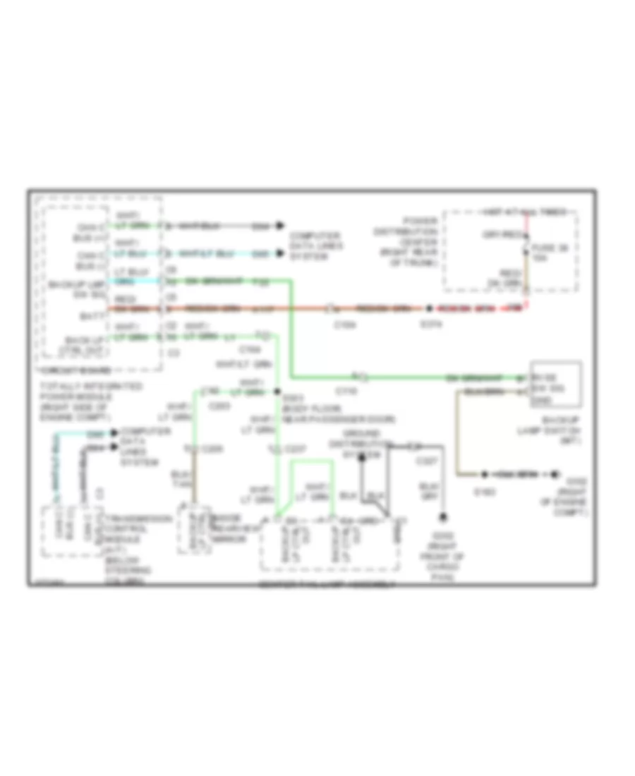
Backup Lamps Wiring Diagram for Dodge Challenger SE 2010
List of elements for Backup Lamps Wiring Diagram for Dodge Challenger SE 2010:
- 38b
- A117
- Backup
- Backup lamp switch (m/t)
- Batt
- Bus (-) can c
- C104
- C110
- C203
- C205
- C237
- C3 out lp ctrl backup
- C327
- C4 out lp ctrl backup
- Can c bus (+)
- Center tail lamp assembly
- Circuit board
- Computer data lines system
- D64
- D65
- Fuse 38 10a
- G102 (right of engine compt)
- G302 (right front of cargo pan)
- Gnd
- Grd
- Ground distribution system
- Hot at all times
- Inside rearview mirror
- Out lp ctrl
- Power distribution center (right rear of trunk)
- Rvse b
- S183
- S374
- Sw sig a
- T22
- Totally integrated power module (right side of engine compt)
- Transmission control module (a/t) (below steering column)
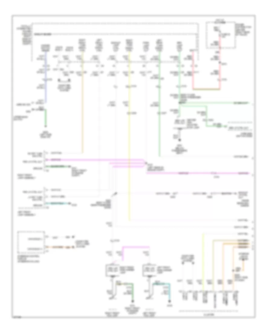
Exterior Lamps Wiring Diagram (1 of 2) for Dodge Challenger SE 2010
List of elements for Exterior Lamps Wiring Diagram (1 of 2) for Dodge Challenger SE 2010:
- 38b
- Backup lamp ctrl out
- Backup lp ctrl out
- Batt
- Brk lamp ctrl out
- Brk lmp ctrl out
- Brk lp ctrl out
- Bus (+) can b
- Bus (-) can b
- C102
- C103
- C104
- C203
- C205
- C307
- C308
- Can b bus (+)
- Can b bus (-)
- Center high mounted stop lamp
- Circuit board
- Cluster
- Computer data lines system
- D54
- D55
- Dimmer sig panel lp
- Fuse 38 10a
- G100
- G101 (right front of engine compt)
- G200 (left side dash of)
- G301 (below passenger's seat)
- Gnd
- Ground
- Hazard switch sense
- Hdlp sw mux
- Hot at all times
- Hzrd sw sig
- Inside rearview mirror
- Interior lights system
- Lamps drv panel
- Left front fog lamp
- Left front lamp assembly
- Left front side marker lamp
- Left front turn signal ctrl
- Left rear turn signal ctrl
- Lh frt turn sig ctrl
- Mux rtn hdlp sw
- Near passenger door) s302
- Park lamp ctrl out
- Power distribution center (right rear of trunk)
- Prk lmp ctrl out
- Prk lp ctrl out
- Rh frt turn sig ctrl
- Right front fog lamp
- Right front lamp assembly
- Right front side marker lamp
- Right front turn signal ctrl
- Right rear turn signal ctrl
- S127 (left rear of engine compt)
- S303 (body floor, near passenger door)
- S374
- Steering control module (steering column)
- Totally integrated power module (right side of engine compt)
- Upper bank switch
- Wireless ignition node
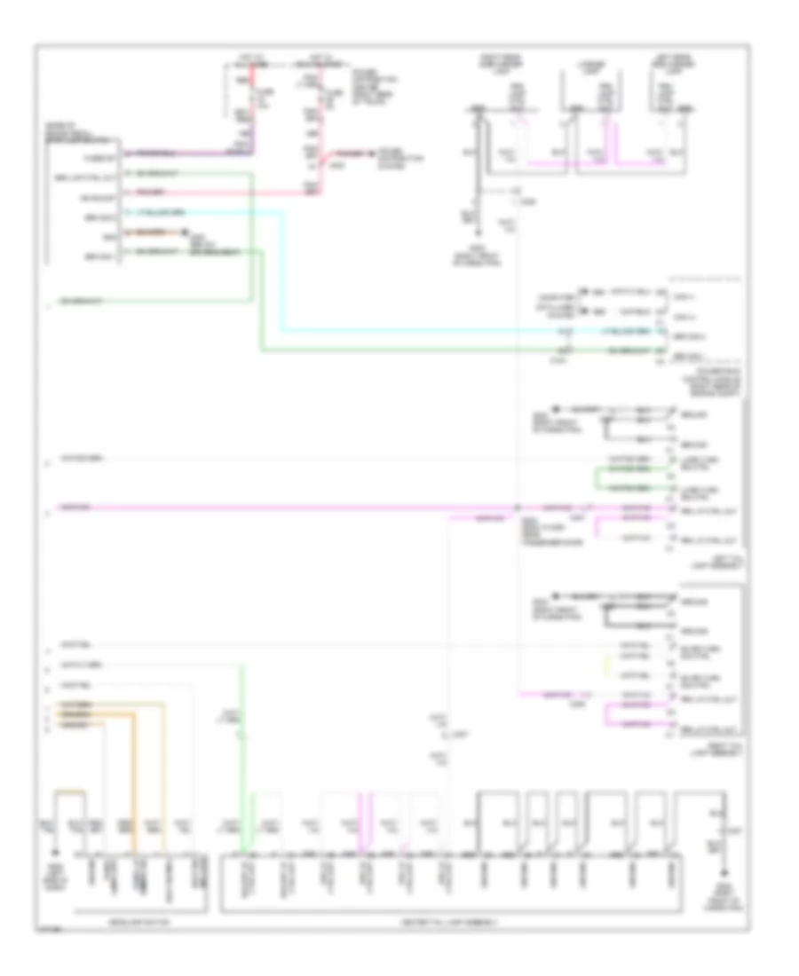
Exterior Lamps Wiring Diagram (2 of 2) for Dodge Challenger SE 2010
List of elements for Exterior Lamps Wiring Diagram (2 of 2) for Dodge Challenger SE 2010:
- (base of brake pedal) stop lamp switch
- 19b
- 29b
- Brk lmp ctrl out
- Brk sig 1
- Brk sig 2
- C104
- C203
- C306
- C307
- C308
- C327
- Can (+)
- Can (-)
- Center tail lamp assembly
- Computer
- Ctrl out backup lp
- Ctrl out prk lp
- D64
- D65
- Data lines
- Dimmer sig panel lp
- Fuse 10a
- Fuse 5a
- Fused bt
- G202 (left side of dash)
- G300 (below driver's seat)
- G302 (right front of cargo pan)
- Gnd
- Grd
- Ground
- Hdlp sw mux
- Headlamp switch
- Hot at all times
- Hot in run or start
- Ign run/st
- Lamps drv panel
- Left rear side marker lamp
- Left tail lamp assembly
- Lh rr turn sig ctrl
- Lh rr turn sig ctrl c1
- License lamp
- Mnr
- Mux rtn hdlp sw
- Power distribution center (right rear of trunk)
- Power distribution system
- Powertrain control module (right rear of engine compt)
- Prk lamp ctrl out
- Prk lp ctrl out
- Red
- Rh rr turn sig ctrl
- Rh rr turn sig ctrl c1
- Right rear side marker lamp
- Right tail lamp assembly
- S304 (body floor, near passenger door)
- System
GROUND DISTRIBUTION
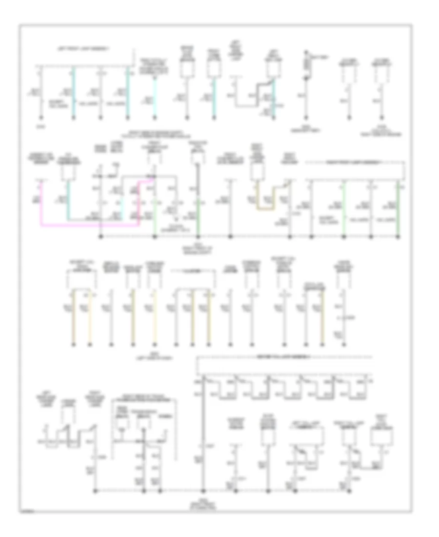
Ground Distribution Wiring Diagram (1 of 3) for Dodge Challenger SE 2010
List of elements for Ground Distribution Wiring Diagram (1 of 3) for Dodge Challenger SE 2010:
- (except 3.6l) passive entry module
- (except 3.6l) radio amplifier
- (right rear of trunk) power distribution center
- (right side of engine compt) totally integrated power module
- 24d
- 33a
- 87a
- A/c pressure transducer
- Ambient air temperature sensor
- Battery
- Brake fluid level sensor
- C103
- C205
- C306
- C307
- C308
- C311
- C327
- Center tail lamp assembly
- Cigar lighter
- Cluster
- Data link connector
- Decklid release switch
- Diode 2
- Evap system monitor switch
- Except hid lamps
- From totally ntegrated power module (diagram 1 of 3)
- Front washer fluid level sensor
- Front washer pump relay
- Front wiper motor
- G100
- G101 (right front of engine compt)
- G109 (3.5l & 5.7l: right side of engine)
- G202 (left side of dash)
- G302 (right front of cargo pan)
- G303 (near battery)
- Grd
- Headlamp switch
- Hid lamps
- Inside rearview mirror
- Left front fog lamp
- Left front lamp assembly
- Left front side marker lamp
- Left rear side marker lamp
- Left tail lamp assembly
- License lamp
- Oxygen sensor 1/1
- Oxygen sensor 2/1
- Radiator fan relay
- Rear wiper relay
- Right front fog lamp
- Right front lamp assembly
- Right front side marker lamp
- Right rear side marker lamp
- Right tail lamp assembly
- Right tail/ stop/ turn lamp
- Steering control module
- Sunroof motor/ module
- To g100 (diagram 1 of 3)
- Transmission relay
- Wiper on/off relay
- Wireless ignition node
- Zener diode
Ground Distribution Wiring Diagram (2 of 3) for Dodge Challenger SE 2010
List of elements for Ground Distribution Wiring Diagram (2 of 3) for Dodge Challenger SE 2010:
- (3.5l) electronic overhead module
- (3.5l) exhaust gas recirculation valve assembly
- (5.7l) multi displacement system cyl 1 solenoid
- (5.7l) multi displacement system cyl 4 solenoid
- (5.7l) multi displacement system cyl 6 solenoid
- (5.7l) multi displacement system cyl 7 solenoid
- (5.7l) variable camshaft timing solenoid
- (6.1l) hands free module
- (m/t) backup lamp switch
- (m/t) reverse lock-out solenoid
- (m/t) skip shift solenoid
- (right rear of engine compt) powertrain control module
- 6.1l
- A/c compressor clutch
- C100
- C101
- C204
- Except 6.1l
- Front a/c heater module
- Front reading lamp
- G102 (right front of engine compt)
- G103
- G104 (3.5l: right side of engine)
- G105 (5.7l & 6.1l: rear of engine)
- G106 (3.5l: left side of engine) (5.7l: rear of engine) (6.1l: left rear of cylinder head)
- G200 (left side of dash)
- G200a
- G201 (right side of dash)
- Hood ajar switch
- Left heated seat switch
- Left vanity lamp
- Occupant restraint controller module
- Oxygen 1/2 sensor
- Oxygen 2/2 sensor
- Radiator fan
- Radio
- Right heated seat switch
- Right vanity lamp
- S154
- S183
- S270
- S349
- Upper bank switch
- Windshield washer pump
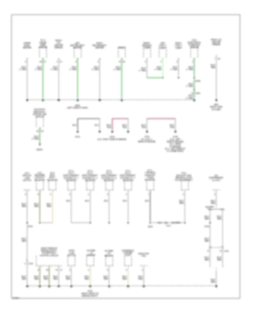
Ground Distribution Wiring Diagram (3 of 3) for Dodge Challenger SE 2010
List of elements for Ground Distribution Wiring Diagram (3 of 3) for Dodge Challenger SE 2010:
- (6.1l) subwoofer amplifier
- (except 3.5l) heated seats module
- (except 3.5l) left front grab handle lamp
- (except 3.5l) right front grab handle lamp
- (except 3.5l) tire pressure module
- (m/t) clutch interlock switch
- (w/ 5 speed transmission) shifter lever assembly
- (w/ 5 speed transmission) transmission control module
- Antilock brakes module
- C300
- C301
- C313
- C314
- C315
- C316
- Center high mounted stop lamp
- Console power outlet
- Cup holder lamp
- Decklid door latch
- Driver door latch
- Driver door module
- Driver outside rearview mirror
- Driver seat belt switch
- Driver seat switch
- Driver window/ door lock switch
- Fuel pump module
- G300 (below driver's seat)
- G301 (below passenger's seat)
- G304 (next to deck lid latch)
- Left rear footwell lamp
- Left seat back heater
- Left seat cushion heater
- Mirror switch
- Passenger door latch
- Passenger door module
- Passenger outside rearview mirror
- Right rear footwell lamp
- Right seat back heater
- Right seat cushion heater
- S333 (below driver seat)
- S334
- S360 (bottom of right front door)
- Stop lamp switch
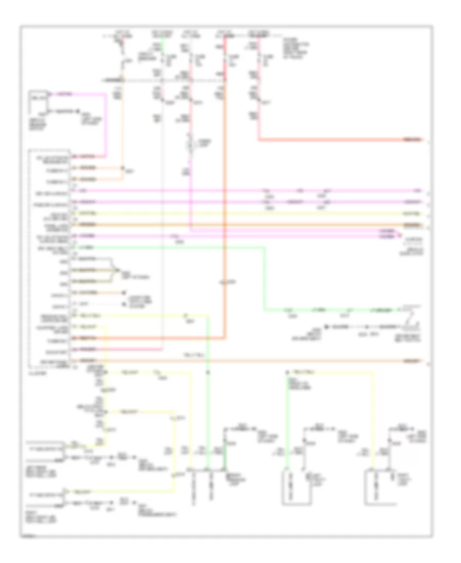
HEADLIGHTS
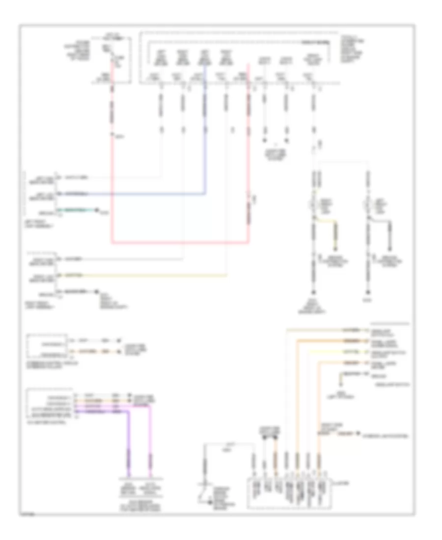
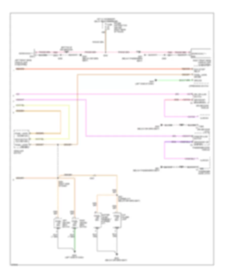
Headlights Wiring Diagram for Dodge Challenger SE 2010
List of elements for Headlights Wiring Diagram for Dodge Challenger SE 2010:
- (right side of dash) s208
- 38b
- A/c heater control
- A117
- Auto headlamps sig
- Auto headlamps signal
- Bus (+) can b
- Bus (-) can b
- C103
- C104
- C203
- Can b bus (+)
- Can b bus (-)
- Circuit board
- Cluster
- Computer data lines system
- D54
- D55
- Front fog lamp/ ind fdi
- Fuse 10a
- G100
- G101 (right front of engine compt)
- G202 (left of dash)
- G939
- Ground
- Ground distribution system
- Headlamp sw mux rtn
- Headlamp switch
- Headlamp switch mux
- Headlamp switch mux rtn
- Hot at all times
- Interior lights system
- L24
- L33
- L34
- L43
- L44
- L89
- Left front fog lamp
- Left front lamp assembly
- Left high beam driver
- Left low beam driver
- Panel lamps dimmer sig
- Panel lamps dimmer signal
- Panel lamps driver
- Park brk sw sns
- Parking brake switch (base of parking brake)
- Power distribution center (right rear of trunk)
- Right front fog lamp
- Right front lamp assembly
- Right high beam driver
- Right low beam driver
- S374
- Steering control module (steering column)
- Sun sensor (w/ auto headlamps) (top center of dash)
- Sun sensor return
- Switch mux headlamp
- Totally integrated power module (right side of engine compt)
HORN
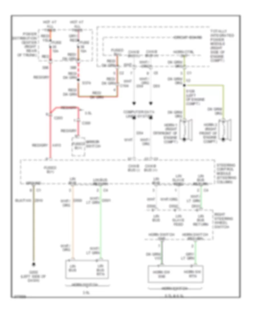
Horn Wiring Diagram for Dodge Challenger SE 2010
List of elements for Horn Wiring Diagram for Dodge Challenger SE 2010:
- 3.5l
- 30b
- 38b
- 5.7l & 6.1l
- C104
- C203
- C300
- Can b bus (+)
- Can b bus (-)
- Circuit board
- Computer data lines system
- D500
- D501
- D502
- D54
- D55
- Fused b(+)
- G202 (left side of dash)
- Ground
- Horn 1 (right front of engine compt)
- Horn 2 (right front of engine compt)
- Horn ctrl out
- Horn sw rtn
- Horn sw sns
- Horn switch
- Horn switch return
- Horn switch sns
- Hot at all times
- Lin bus
- Lin bus return
- Lin bus rtn
- Lin slave feed
- Mirror switch
- Power distribution center (right rear of trunk)
- Red
- Right steering wheel switch
- S128 (left of engine compt)
- S374
- Steering control module (steering column)
- Totally integrated power module (right side of engine compt)
- Z910
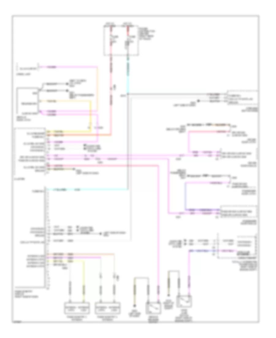
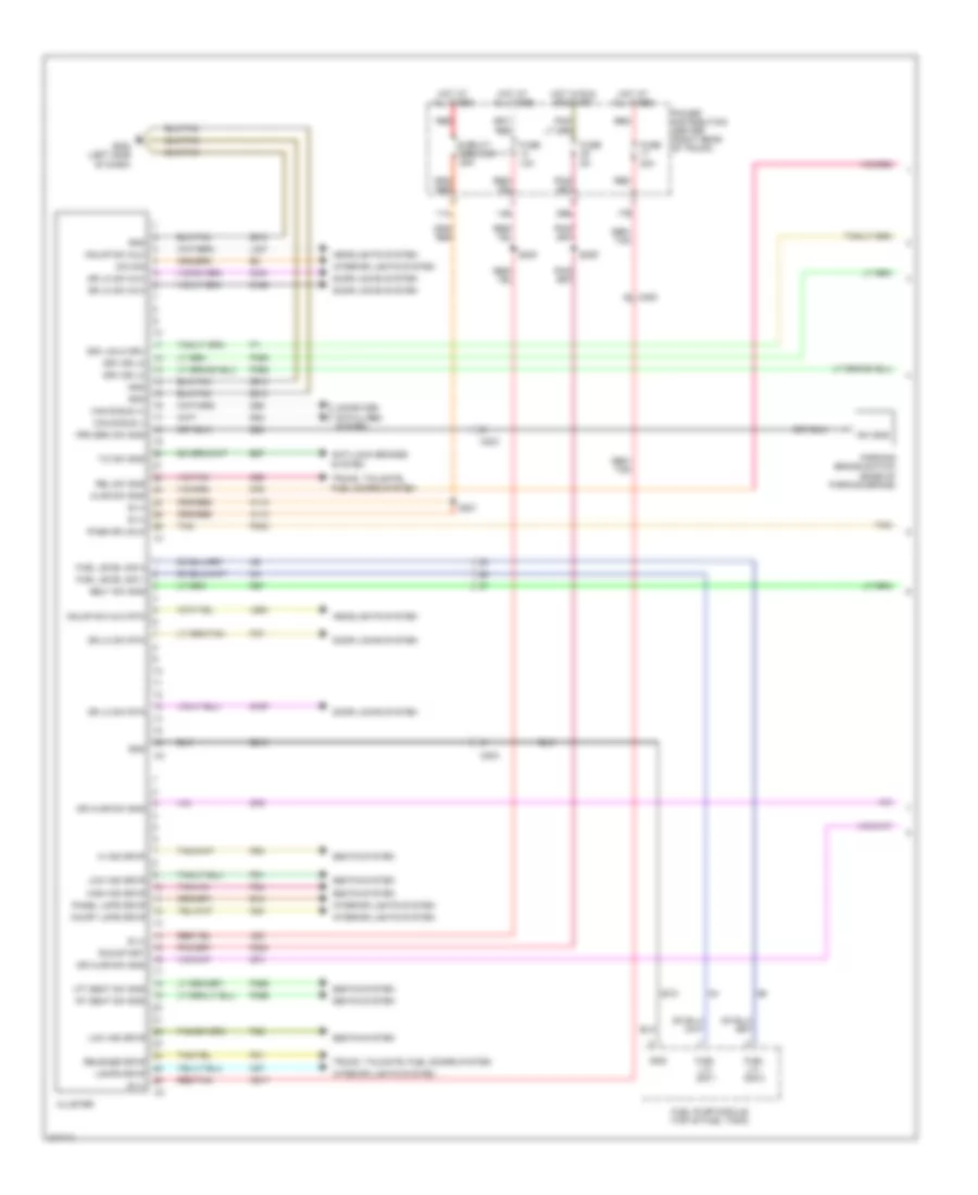
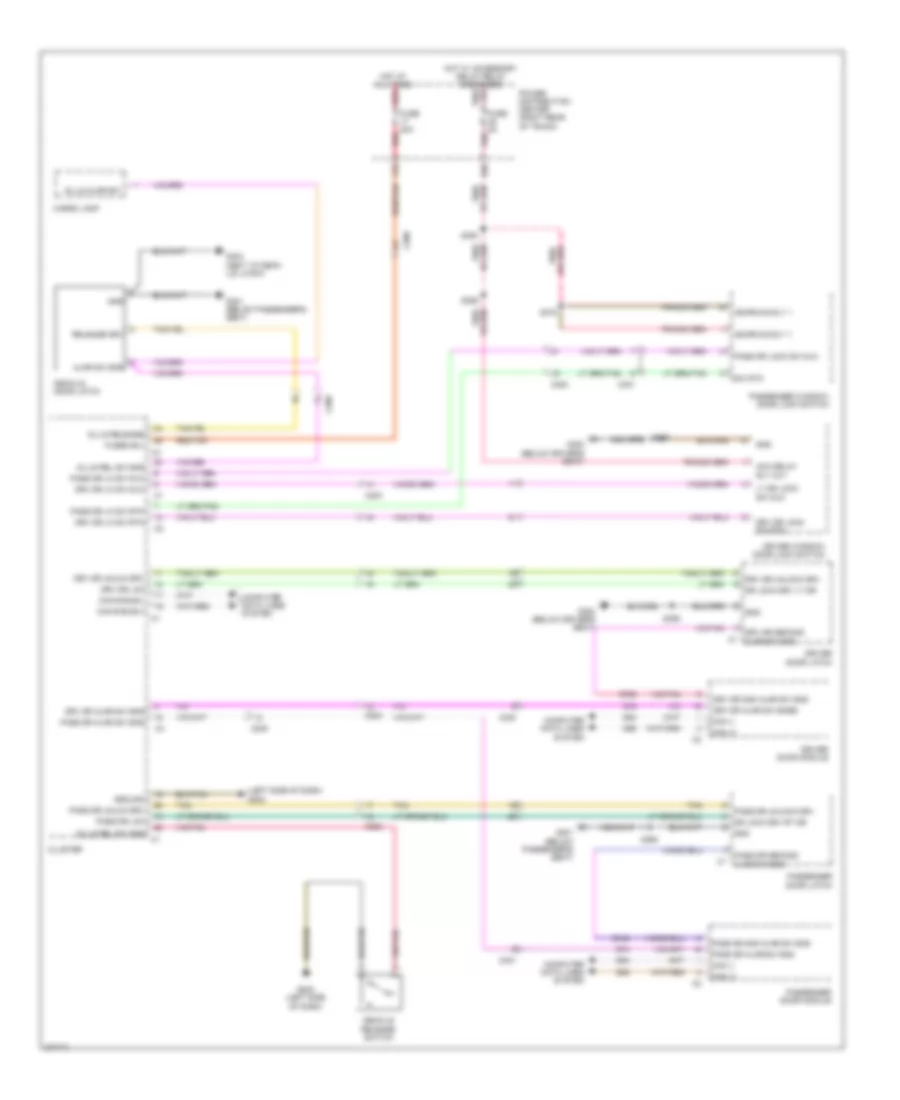
INSTRUMENT CLUSTER
Instrument Cluster Wiring Diagram (1 of 2) for Dodge Challenger SE 2010
List of elements for Instrument Cluster Wiring Diagram (1 of 2) for Dodge Challenger SE 2010:
- 11a
- 14b
- 17b
- 29b
- A110
- A23
- A917
- Ajar sw sns
- Anti-lock brakes system
- B (+)
- B25
- B27
- Belt sw sns
- C200
- C203
- Can b bus (+)
- Can b bus (-)
- Circuit breaker 11 25a
- Cluster
- Computer data lines system
- Court lmps drvr
- D54
- D55
- Dim sig
- Door locks system
- Dr ajar sw sns
- Dr lk sw mux
- Dr lk sw rtn
- Drv dr lk
- Drv unlk drv
- E12
- F202
- Fuel level sig 1
- Fuel level sig 2
- Fuel lvl sig 1
- Fuel lvl sig 2
- Fuel pump module (top of fuel tank)
- Fuse 10a
- Fuse 20a
- Fuse 5a
- G160
- G161
- G167
- G202 (left side of dash)
- G25
- G74
- G75
- G78
- Gnd
- Hdlmp sw mux
- Hdlmp sw mux rtn
- Headlights system
- Hi ind drvr
- High ind drvr
- Hot at all times
- Hot in run or start
- Interior lights system
- L307
- L900
- Lamps drvr
- Lft seat sw sns
- Low ind drvr
- M24
- M27
- P303
- P31
- P365
- P366
- P37
- P392
- P393
- P81
- P82
- P83
- P84
- Panel lmps drvr
- Parking brake switch (base of parking brake)
- Pass dr unlk
- Power distribution center (right rear of trunk)
- Prk brk sw sns
- R57
- Red
- Red/ tan
- Red/tan
- Rel sw sns
- Release drvr
- Rt seat sw sns
- Run-start
- S200
- S201
- S209
- Seats system
- Sw sns
- T/c sw sns
- Tan
- Trunk, tailgate, fuel doors system
- Z210
- Z910
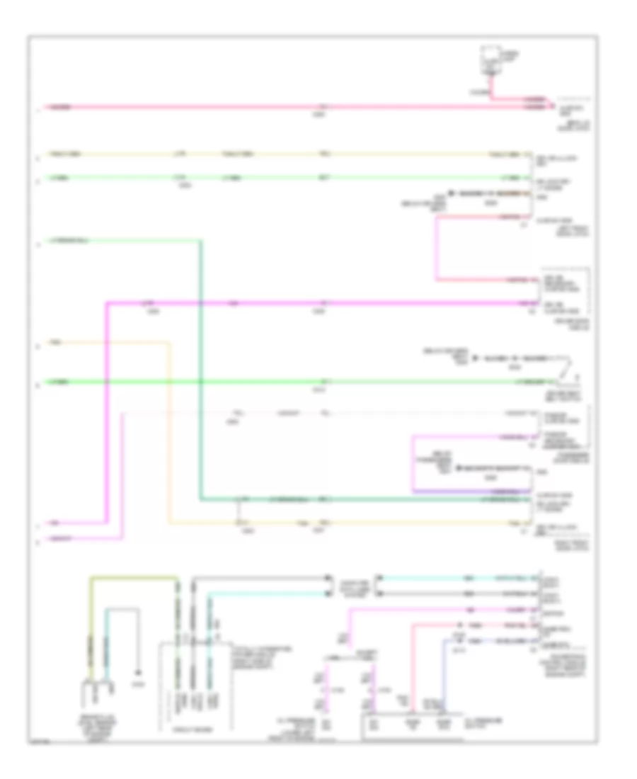
Instrument Cluster Wiring Diagram (2 of 2) for Dodge Challenger SE 2010
List of elements for Instrument Cluster Wiring Diagram (2 of 2) for Dodge Challenger SE 2010:
- (below driver's seat) g300
- (below passenger's seat) g301
- 3.5l
- Ajar sw sns
- B20
- Brake fluid level sensor (left rear of engine compt)
- Bus (+)
- Bus(-)
- C100
- C200
- C203
- C300
- C301
- C313
- Can c bus (+)
- Can c bus (-)
- Cargo lamp
- Circuit board
- Computer data lines system
- D64
- D65
- Deck lid door latch
- Dr lock drv lt doors
- Driver door module
- Driver seat belt switch
- Drv dr ajar sw sns
- Drv dr secondary ajar sw sns
- Drv dr ullock drv
- Eop sig
- Except 3.5l
- F855
- G100
- G300 (below driver's seat)
- Gnd
- K900
- Left front door latch
- Oil pressure switch
- Oil pressure switch (lower left front of engine)
- Pass dr ajar sw sns
- Pass dr secondary ajar sw sns
- Passenger door module
- Powertrain control module (right rear of engine compt)
- Right front door latch
- S105
- S110
- S333
- S355
- S360
- Sens
- Snsr fd
- Snsr prim fd
- Snsr rtn
- Sw sig
- Tan
- Totally integrated power module (right side of engine compt)
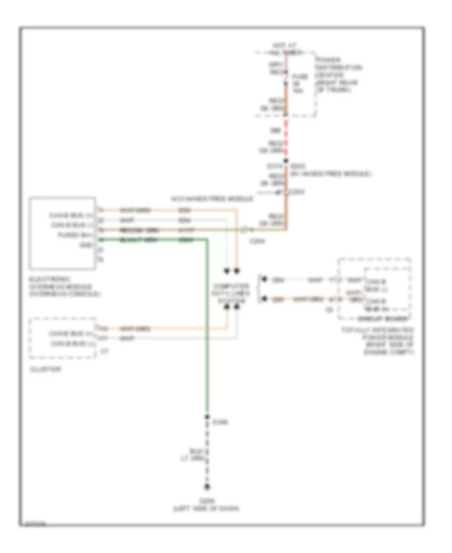
Overhead Console Wiring Diagram for Dodge Challenger SE 2010
List of elements for Overhead Console Wiring Diagram for Dodge Challenger SE 2010:
- 38b
- A117
- C203
- C204
- Can b bus (+)
- Can b bus (-)
- Circuit board
- Cluster
- Computer data lines system
- D54
- D55
- Electronic overhead module (overhead console)
- Fuse 10a
- Fused b(+)
- G200 (left side of dash)
- Gnd
- Hot at all times
- Power distribution center (right rear of trunk)
- S202 s374
- S349
- Totally integrated power module (right side of engine compt)
- W/o hands free module
- Z909
INTERIOR LIGHTS
Interior Lights Wiring Diagram (1 of 2) for Dodge Challenger SE 2010
List of elements for Interior Lights Wiring Diagram (1 of 2) for Dodge Challenger SE 2010:
- (below passenger's seat)
- (center of dash) s227
- 11a
- 17b
- 24b
- 25a
- 38b
- 40b
- Ajar sig
- C200
- C203
- C204
- C300
- C301
- C313
- C314
- C315
- C316
- Can b (+)
- Can b (-)
- Cargo lamp
- Circuit breaker
- Cluster
- Computer data lines system
- Courtesy lmps driver
- Decklid door latch
- Decklid release switch
- Dk lid/liftgate ajar sw sens
- Dk lid/liftgate release sw
- Driver panel lamps
- Driver seat belt switch
- Drv dr ajar sw
- Drv seat belt sw sns
- Ft hdr crtsy fd
- Fuse 10a
- Fuse 20a
- Fuse 5a
- Fused b (+)
- Fused b(+)
- G200 (left side of dash)
- G202 (left of dash)
- G202 (left side of dash)
- G300 (below driver's seat)
- G301
- Gnd
- Gnd front reading lamp
- Hdlp sw mux return
- Hot at all times
- Hot in run or start
- Left rear seat back led footwell lamp
- Left vanity lamp
- Panel lmps dimmer sig
- Pass dr ajar sw
- Power distribution center (right rear of trunk)
- Rail lamp fds
- Reading/ rail lamps driver
- Red
- Red b
- Red/ tan
- Red/tan
- Rel sw
- Right seat back led footwell lamp
- Right vanity lamp
- Run-start
- S201
- S209
- S217
- S333
- S341 (front of headliner)
- S349
- S374
- Z911
- Z912
Interior Lights Wiring Diagram (2 of 2) for Dodge Challenger SE 2010
List of elements for Interior Lights Wiring Diagram (2 of 2) for Dodge Challenger SE 2010:
- (bottom of driver door) s356
- 35b
- Ajar sw
- C203
- Cup holder lamp
- Driver door latch
- Driver door module
- Drv dr ajar switch
- F880
- Fuse 5a
- G200 (left side of dash)
- G300 (below driver's seat)
- G301 (below passenger's seat)
- G74
- G745
- G75
- G755
- Gnd
- Gnd c1
- Ground
- Hdlp switch mux return
- Headlamp switch
- Hot w/ accessory delay relay energized
- Ign/rn/ac/dly 1
- Left front grab handle lamp (if equipped)
- Left heated seat switch
- Panel lamps dimmer sig
- Panel lamps driver
- Panel lps drv
- Pass dr ajar switch
- Passenger door latch
- Passenger door module
- Power distribution center (right rear of trunk)
- Right front grab handle lamp (if equipped)
- Right heated seat switch
- Run/ start relay
- S208 (right side of dash)
- S300
- S355
- S360
- S372
- S387 (5 speed a/t) (below driver's seat)
- Secondary dr ajar sw c2
- Shifter lever assembly (5 speed a/t)
- Upper bank switch
- Z911
- Z912
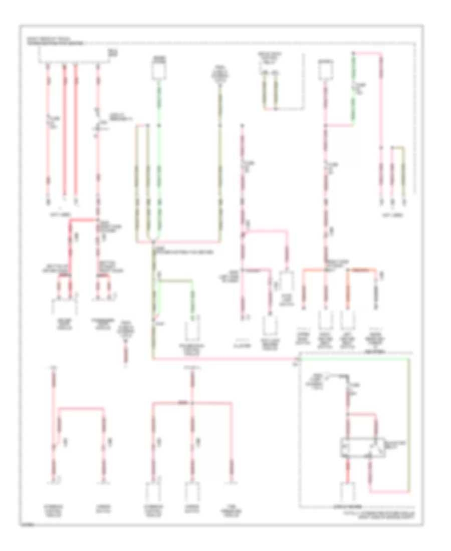
POWER DISTRIBUTION
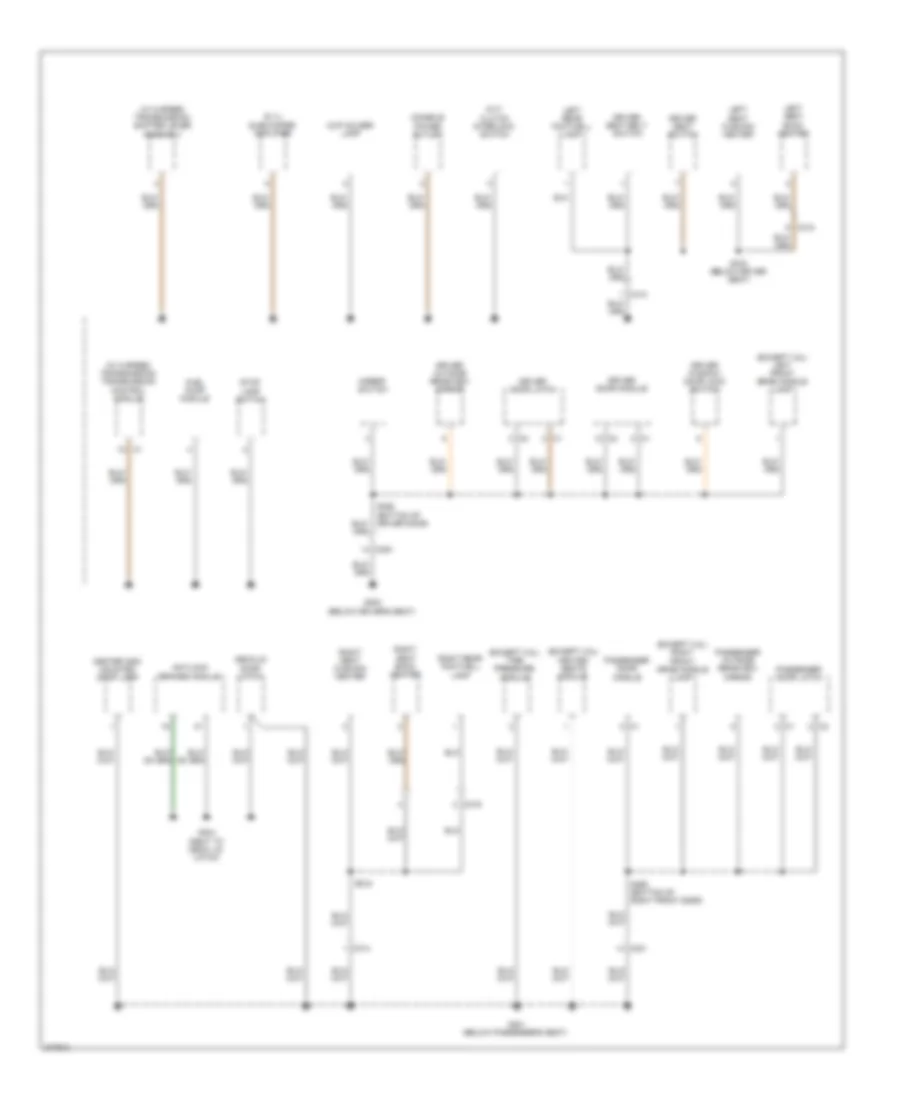
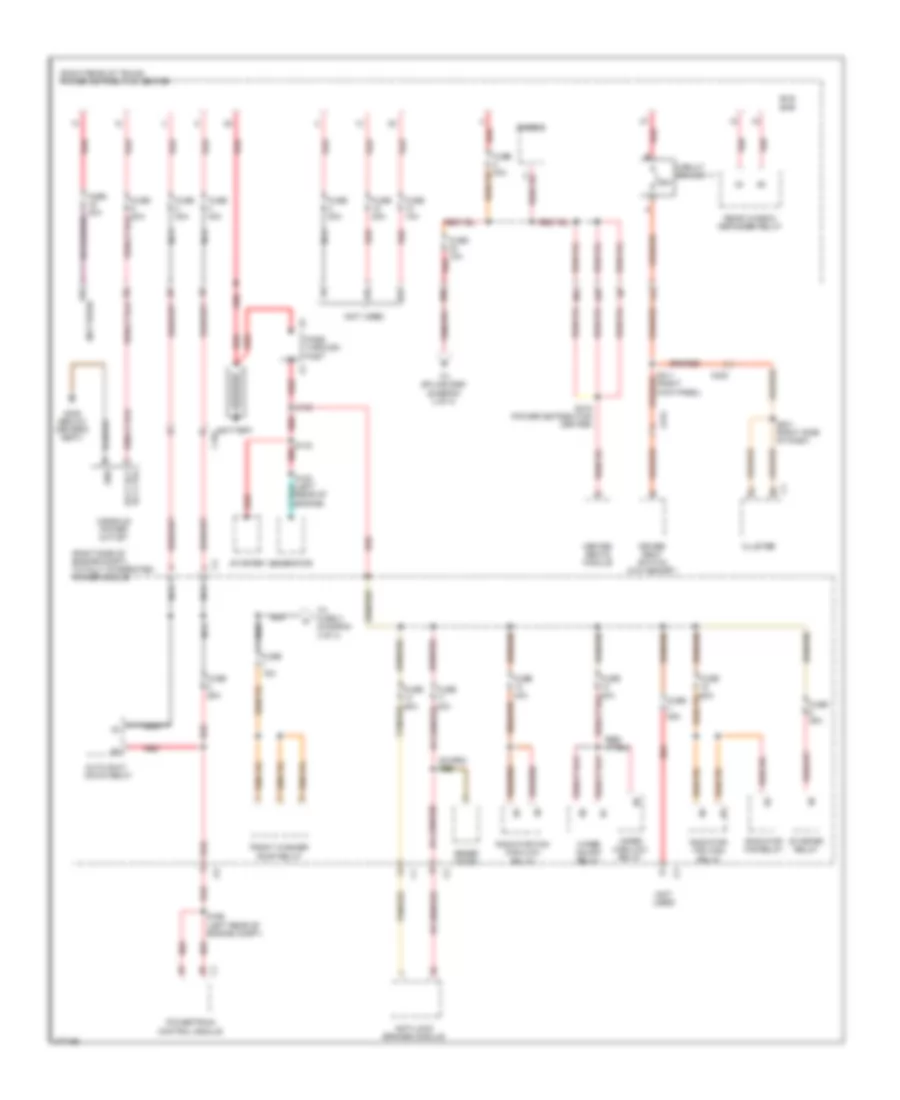
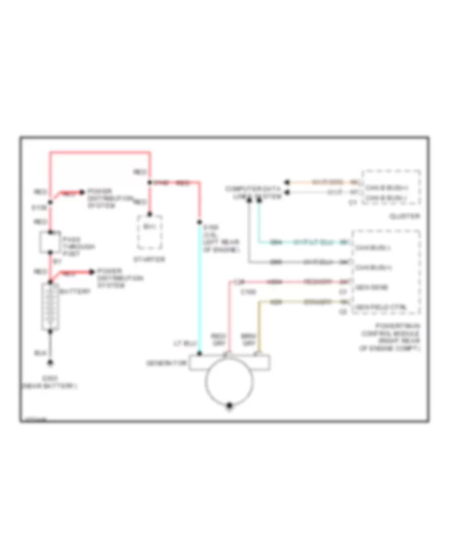
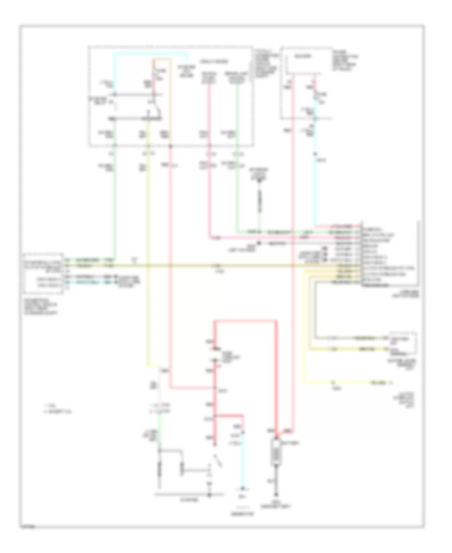
Power Distribution Wiring Diagram (1 of 4) for Dodge Challenger SE 2010
List of elements for Power Distribution Wiring Diagram (1 of 4) for Dodge Challenger SE 2010:
- (not used)
- (right kick panel)
- (right rear of trunk) power distribution center
- (right side of engine compt) totally integrated power module
- 10a
- 11a
- 15b
- 16b
- 25a
- 30a
- 30b
- 33b
- Accy dly rly ctrl
- Anti-lock brakes module
- Auto shut down relay
- Bar
- Battery
- Bus
- C104
- C200
- C313
- Circuit braker 11
- Cluster
- Console power outlet
- Diode 2
- Driver seat switch (w/o memory)
- Front washer pump relay
- Fuse 10a
- Fuse 15a
- Fuse 20a
- Fuse 25a
- Fuse 40a
- Fuse 50a tan/red
- G300 (below driver's seat)
- Generator
- Gnd
- Heated seats module
- Nca
- Pass through post
- Powertrain control module
- Radiator fan high relay
- Radiator fan high/low relay
- Radiator fan relay
- Rear window defogger relay
- Red
- S100 (left rear of engine)
- S138
- S142 red
- S166 (left rear of engine compt)
- S201 (right side of dash)
- S315 (power distribution center)
- Starter
- Starter relay
- Tan/red
- To fuse 3 (diagram 4 of 4)
- To splice s309 (diagram 4 of 4)
- Wiper high/low relay
- Wiper on/off relay
- Zener diode
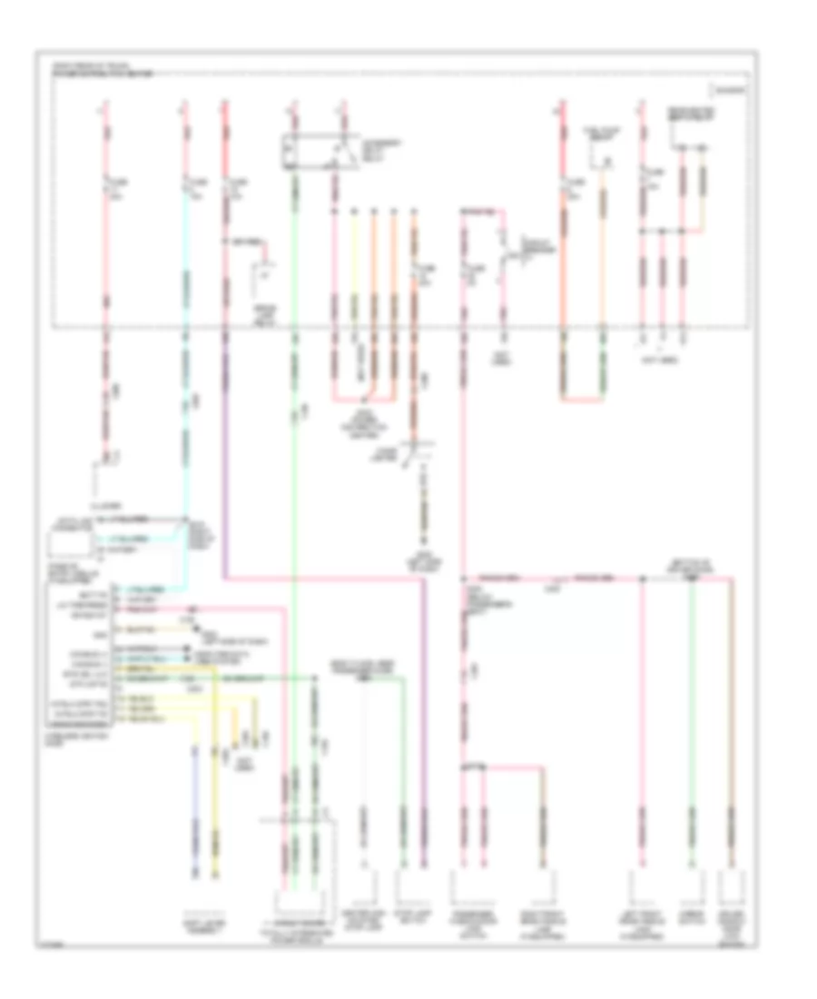
Power Distribution Wiring Diagram (2 of 4) for Dodge Challenger SE 2010
List of elements for Power Distribution Wiring Diagram (2 of 4) for Dodge Challenger SE 2010:
- (body floor, near passenger door) s302
- (bottom of driver door) s356
- (not used)
- (right rear of trunk) power distribution center
- 13a
- 13b
- 17b
- 18b
- 18c
- 19b
- 23b
- 23c
- 25a
- 35a
- 35b
- 46a
- 47a
- 47c
- Accessory delay relay
- Batt fd
- Brake lamp relay
- Btsi sol ulk
- Bus bar
- C102
- C104
- C200
- C203
- C300
- C301
- Can bus (+)
- Can bus (-)
- Center high mounted stop lamp
- Cigar lighter
- Circuit board
- Circuit breaker
- Cluster
- Computer data lines system
- Data link connector
- Driver window/ door lock switch
- Fuel pump relay
- Fuse 15a
- Fuse 20a
- Fuse 5a
- G202 (left side of dash)
- Gnd
- Ign run st
- Intrlk strt fd
- Intrlk strt fd2
- Left front grab handle lamp (if equipped)
- Lin tire press
- Mirror switch
- Passenger window/door lock switch
- Passive entry module (if equipped)
- Pnk
- Rear heated seats relay
- Red
- Red/tan
- Right front grab handle lamp (if equipped)
- S215 (right side of dash)
- S300 (below passenger's seat)
- S323 (power distribution center)
- S372
- Shift lever assembly
- Stop lamp switch
- Stp lmp fd
- Totally integrated power module
- Trans rng park
- Wireless ignition node
Power Distribution Wiring Diagram (3 of 4) for Dodge Challenger SE 2010
List of elements for Power Distribution Wiring Diagram (3 of 4) for Dodge Challenger SE 2010:
- (not used)
- (power distribution center)
- (right rear of trunk) power distribution center
- 14a
- 14b
- 21b
- 21c
- 27b
- 28a
- 31a
- 36a
- 36b
- 38a
- 38b
- 41a
- 41b
- 42a
- 42b
- 44a
- 44b
- 47d
- A/c heater control
- Blower motor
- Bus bar
- C104
- C200
- C202
- C203
- C204
- C311
- Cargo lamp
- Circuit board
- Cluster
- Diode
- Electronic overhead module (if equipped)
- Fuse
- Fuse 10a
- Fuse 20a
- Fuse 30a
- Handsfree module (if equipped)
- Iod-pdc
- Occupant restraint controller module
- Radio
- Radio amplifier (if equipped)
- Rear heated seats relay
- Red
- Run relay
- S200
- S202
- S203
- S210 (right side of dash)
- S321
- S322 (power distribution center)
- S374
- Sunroof module/motor (if equipped)
- To fuse 40 (diagram 4 of 4)
- Totally integrated power module (right side of engine compt)
- Transmission relay
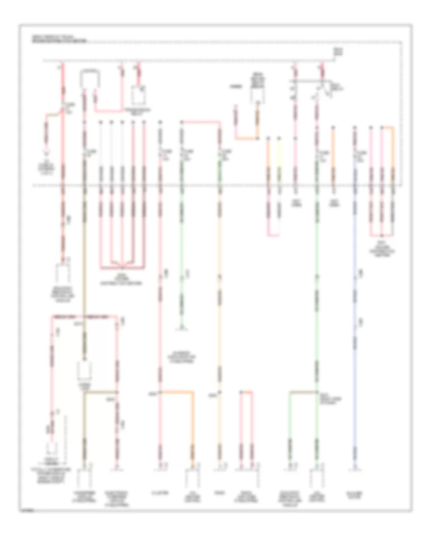
Power Distribution Wiring Diagram (4 of 4) for Dodge Challenger SE 2010
List of elements for Power Distribution Wiring Diagram (4 of 4) for Dodge Challenger SE 2010:
- (bottom of driver door) s359
- (bottom of right front door) s371
- (not used)
- (right rear of trunk) power distribution center
- (right side of dash) s217
- 11b
- 12b
- 20b
- 25a
- 27a
- 28b
- 29a
- 29b
- 3.5l
- 32a
- 34a
- 34d
- 40a
- 40b
- 5.7l/6.1l
- Anti-lock brakes module
- Bus bar
- C102
- C104
- C200
- C203
- C205
- C300
- C301
- Circuit board
- Circuit breaker 12
- Cluster
- Diode 2
- Drive train control relay
- Driver door module
- From a fuse 1 (diagram 1 of 4)
- From fuse 27 (diagram 3 of 4)
- From fuse 30 (diagram 1 of 4)
- Fuse 10a
- Fuse 20a
- Fuse 5a
- Inside rearview mirror (if equipped)
- Left heated seat switch
- Mirror switch
- Nca
- Passenger door module
- Powertrain control module
- Red
- Right heated seat switch
- Run/start relay
- S167
- S209 (left side of dash)
- S305 (right side of dash)
- S309
- S389 (power distribution center)
- Steering control module
- Stop lamp switch
- Tire pressure module
- Totally integrated power module (right side of engine compt)
- Upper bank switch
- Zener diode
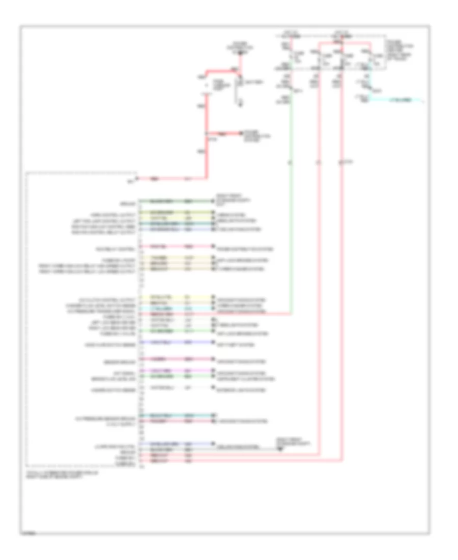
POWER DOOR LOCKS
Power Door Locks Wiring Diagram for Dodge Challenger SE 2010
List of elements for Power Door Locks Wiring Diagram for Dodge Challenger SE 2010:
- (left side of dash) g202
- 17b
- 35b
- Acc delay rly out
- Ajar sw sns
- C200
- C203
- C300
- C301
- Can (+)
- Can (-)
- Can b bus(+)
- Can b bus(-)
- Cargo lamp
- Cluster
- Computer data lines system
- D54
- D55
- Decklid door latch
- Decklid release switch
- Dl/lg ajar sw
- Dl/lg rel sw sns
- Dl/lg release
- Dr lock drv lt dr
- Dr lock drv rt dr
- Driver door latch
- Driver door module
- Driver window/ door lock switch
- Drv dr 2nd ajar sw sns
- Drv dr ajar sw sns
- Drv dr ajar sw snse
- Drv dr lck
- Drv dr lk sw mux
- Drv dr lk sw rtn
- Drv dr lock sw rtn
- Drv dr second ajar sw sns
- Drv dr unlck drv
- Drv dr unlock drv
- Fuse 20a
- Fuse 5a
- Fused b(+)
- G202 (left side of dash)
- G300 (below driver's seat)
- G301 (below passenger's seat)
- G304 (next to deck lid latch)
- G74
- G745
- G75
- G755
- Gnd
- Ground
- Hot at all times
- Ign/rn/ac/dly 1
- Lt dr lock sw mux
- Pass dr 2nd ajar sw sns
- Pass dr ajar sw sns
- Pass dr lck
- Pass dr lk sw mux
- Pass dr lk sw rtn
- Pass dr lock sw mux
- Pass dr second ajar sw sns
- Pass dr unlck drv
- Pass dr unlock drv
- Passenger door latch
- Passenger door module
- Passenger window/ door lock switch
- Pnk
- Power distribution center (right rear of trunk)
- Red
- Red/tan
- Release drv
- S300
- S355
- S356
- S360
- S372
- Sw rtn
- Tan
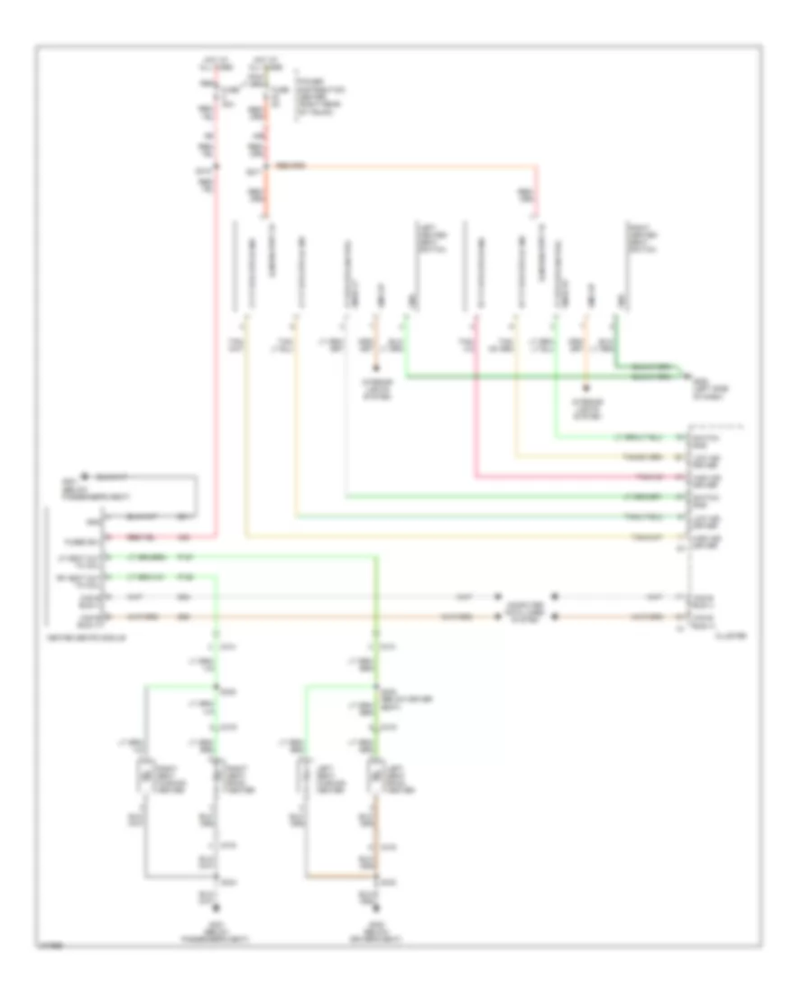
POWER MIRRORS
Automatic Day/Night Mirror Wiring Diagram for Dodge Challenger SE 2010
List of elements for Automatic Day/Night Mirror Wiring Diagram for Dodge Challenger SE 2010:
- (left side of dash) g202
- 40b
- Backup lamp
- Backup lamp feed
- C104
- C203
- C205
- Circuit board
- Exterior lights system
- F23
- Fuse 5a
- Fused run/start relay
- Ground
- Hands free module (right side of dash)
- Hot in run or start
- Inside rearview mirror
- Microphone 1 in (+)
- Microphone 2 in (+)
- Microphone feed
- Microphone in (-)
- Power distribution center (right rear of trunk)
- S217
- S303 (body floor, near passenger door)
- Sensor ground
- Totally integrated power module (right side of engine compt)
- X712
- X722
- X792
- X793
- X835
- Z910
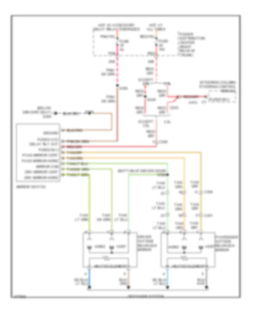
Power Mirrors Wiring Diagram for Dodge Challenger SE 2010
List of elements for Power Mirrors Wiring Diagram for Dodge Challenger SE 2010:
- (below driver's seat) g300
- (bottom of driver door) s358
- (steering column) steering control module
- 3.5l
- 30b
- 35b
- A913
- C203
- C300
- C301
- Defogger system
- Delay rly out
- Driver outside rearview mirror
- Drv mirror horiz
- Drv mirror vert
- Except 3.5l
- Fuse 10a
- Fuse 5a
- Fused acc
- Fused b(+)
- Ground
- Heated element
- Horiz
- Hot at all times
- Hot w/ accessory delay relay energized
- Mirror com
- Mirror switch
- Pass mirror horiz
- Pass mirror vert
- Passenger outside rearview mirror
- Pnk
- Power distribution center (right rear of trunk)
- Red
- S309
- S355
- S356
- Vert
- Vert m
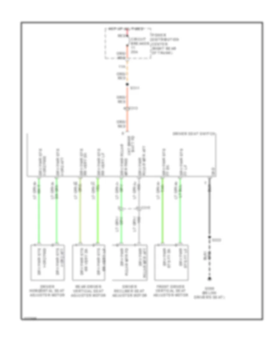
POWER SEATS
Driver Power Seat Wiring Diagram for Dodge Challenger SE 2010
List of elements for Driver Power Seat Wiring Diagram for Dodge Challenger SE 2010:
- 11a
- C313
- C315
- Circuit breaker 25a
- Ckt brkr batt fd
- Driver horizontal seat adjuster motor
- Driver recliner seat adjuster motor
- Driver seat switch
- Drv pwr
- Drv pwr sts
- Front driver vertical seat adjuster motor
- Ft dn drv pwr sts
- Ft up drv pwr sts
- G300 (below driver's seat)
- Gnd
- Horz aft drv pwr sts
- Horz fwd
- Horz fwd drv pwr sts
- Hot at all times
- Mtr fwd drv pwr rclnr
- Power distribution center (right rear of trunk)
- Rclnr mtr aft drv pwr
- Rclnr mtr fd
- Rear driver vertical seat adjuster motor
- Red
- Rr vert dn drv pwr sts
- Rr vert up
- Rr vert up drv pwr sts
- S311
- S333
- Sts ft dn drv pwr
- Sts ft up
Heated Seats Wiring Diagram for Dodge Challenger SE 2010
List of elements for Heated Seats Wiring Diagram for Dodge Challenger SE 2010:
- 40b
- A33
- C313
- C314
- C315
- C316
- Can b bus (+)
- Can b bus (-)
- Cluster
- Computer data lines system
- D54
- D55
- Dim 3 ip
- Fuse 30a
- Fuse 5a
- Fused b(+)
- G200 (left side of dash)
- G300 (below driver's seat)
- G301 (below passenger's seat)
- Gnd
- Heated seats module
- High ind driver
- Hot at all times
- Illm rn strt fd
- Illm run strt fd
- Interior lights system
- Left heated seat switch
- Left seat back heater
- Left seat cushion heater
- Lf heat out to coil
- Low ind driver
- Lt ft htd sts hi ind
- Lt ft htd sts lo ind
- P187
- P188
- Power distribution center (right rear of trunk)
- Red
- Rf heat out to coil
- Right heated seat switch
- Right seat back heater
- Right seat cushion heater
- Rt ft htd sts hi ind
- Rt ft htd sts lo ind
- S217
- S315
- S332 (below driver seat)
- S333
- S334
- S335
- Snse lt ft htd sts sw pos
- Snse rt ft htd sts sw pos
- Switch sns
- Z911
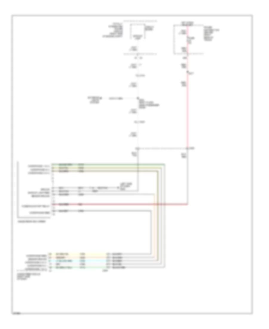
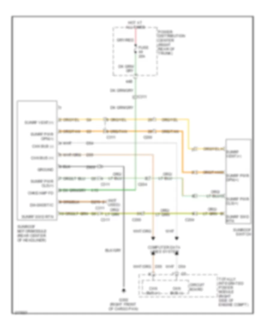
POWER TOP/SUNROOF
Power Top/Sunroof Wiring Diagram for Dodge Challenger SE 2010
List of elements for Power Top/Sunroof Wiring Diagram for Dodge Challenger SE 2010:
- (not used)
- 44b
- C200
- C204
- C311
- Can bus (+)
- Can bus (-)
- Chke/amp fd
- Circuit board
- Computer data lines system
- D270
- D54
- D55
- Diagnostic
- Fuse 20a
- G302 (right front of cargo pan)
- Ground
- Hot at all times
- Power distribution center (right rear of trunk)
- Sunrf pwr cls(+)
- Sunrf pwr opn(+)
- Sunrf swd rtn
- Sunrf vent(+)
- Sunroof motor/module (rear center of headliner)
- Sunroof switch
- Totally integrated power module (right side of engine compt)
- X13
- Z909
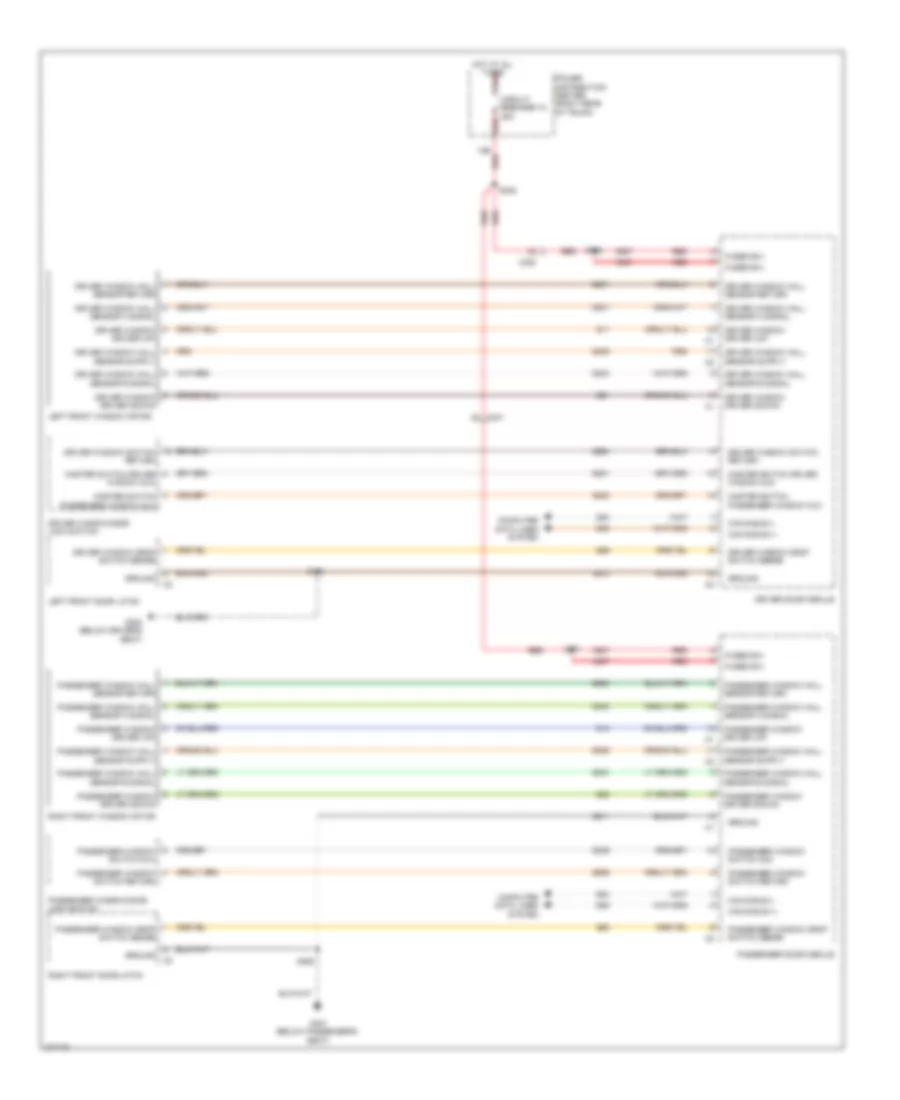
POWER WINDOWS
Power Windows Wiring Diagram for Dodge Challenger SE 2010
List of elements for Power Windows Wiring Diagram for Dodge Challenger SE 2010:
- 12b red
- A937
- C300
- C301
- Can b bus (+)
- Can b bus (-)
- Circuit breaker 12 25a
- Computer data lines system
- D54
- D55
- Driver door module
- Driver window driver (down)
- Driver window driver (up)
- Driver window drop switch sense
- Driver window hall sensor a signal
- Driver window hall sensor b signal
- Driver window hall sensor return
- Driver window switch return
- Driver window/door lock switch
- Fused b(+)
- G300 (below driver's seat)
- G301 (below passenger's seat)
- Ground
- Hot at all times red
- Left front door latch
- Left front window motor
- Master switch driver window mux
- Master switch passenger window mux
- Passenger door module
- Passenger window driver (down)
- Passenger window driver (up)
- Passenger window drop switch sense
- Passenger window hall sensor a signal
- Passenger window hall sensor b signal
- Passenger window hall sensor return
- Passenger window switch mux
- Passenger window switch return
- Passenger window/door lock switch
- Power distribution center (right rear of trunk)
- Q11
- Q12
- Q21
- Q22
- Q221
- Q222
- Q301
- Q302
- Q303
- Q304
- Q305
- Q306
- Q336
- Q58
- Q59
- Q936
- Q990
- Q991
- Q994
- Red
- Right front door latch
- Right front window motor
- S305
- S355
- S359
- S360
- S371
- Z911
- Z912
RADIO
Hands Free Module Wiring Diagram for Dodge Challenger SE 2010
List of elements for Hands Free Module Wiring Diagram for Dodge Challenger SE 2010:
- (left side of dash) g202
- (not used) (not used) c241
- (not used) c241
- 10a
- 38b
- 40b
- A117
- Backup lamp feed
- C205
- C241
- Common audio out
- Computer data
- D54
- D55
- Exterior lights system
- F23
- Fuse 5a
- Fused ign sw output
- G200 (left side of dash)
- Ground
- Hands free module (right side of dash)
- Hot at all times
- Hot w/ run/start relay energized
- Inside rearview mirror
- Left audio out
- Lines system
- Media port
- Microphone 1 in (+)
- Microphone 2 in (+)
- Microphone feed
- Microphone in (-)
- Nca
- Pnk
- Power distribution center (right rear of trunk)
- Radio
- Red
- Right audio out
- S202
- S217
- S250
- Sens gnd
- Tan
- Uci audio lh input
- Uci audio reference
- Uci audio rh input
- Uci audio rt input
- Uci device detect
- Uci ext receive
- Uci ext transmit
- Uci id
- Uci pwr feed 2 pass through
- Uci pwr feed pass through
- Uci pwr feed passthrough
- Uci shield
- Uci usb data (+)
- Uci usb data (-)
- X430
- X431
- X434
- X435
- X436
- X437
- X439
- X440
- X441
- X444
- X445
- X446
- X703
- X704
- X712
- X722
- X792
- X793
- X795
- X835
- Z433
- Z909
- Z910
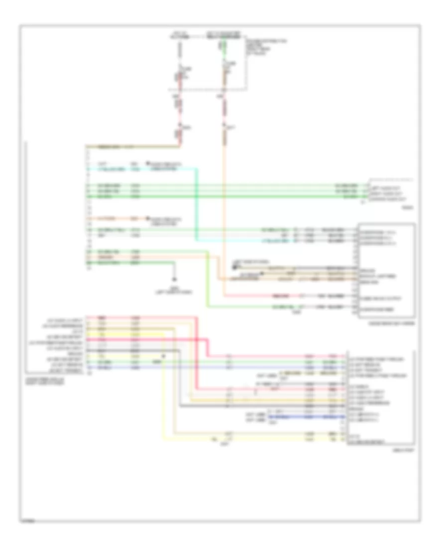
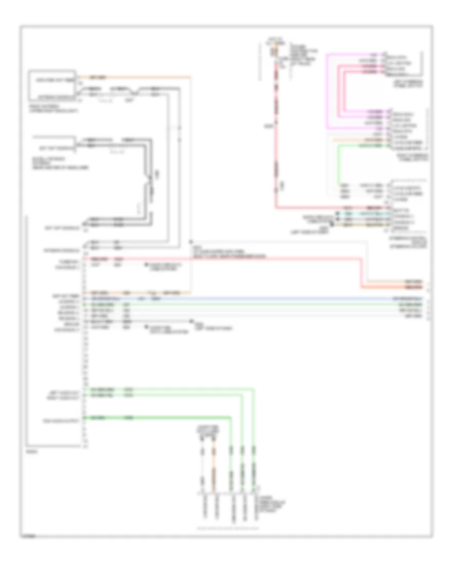
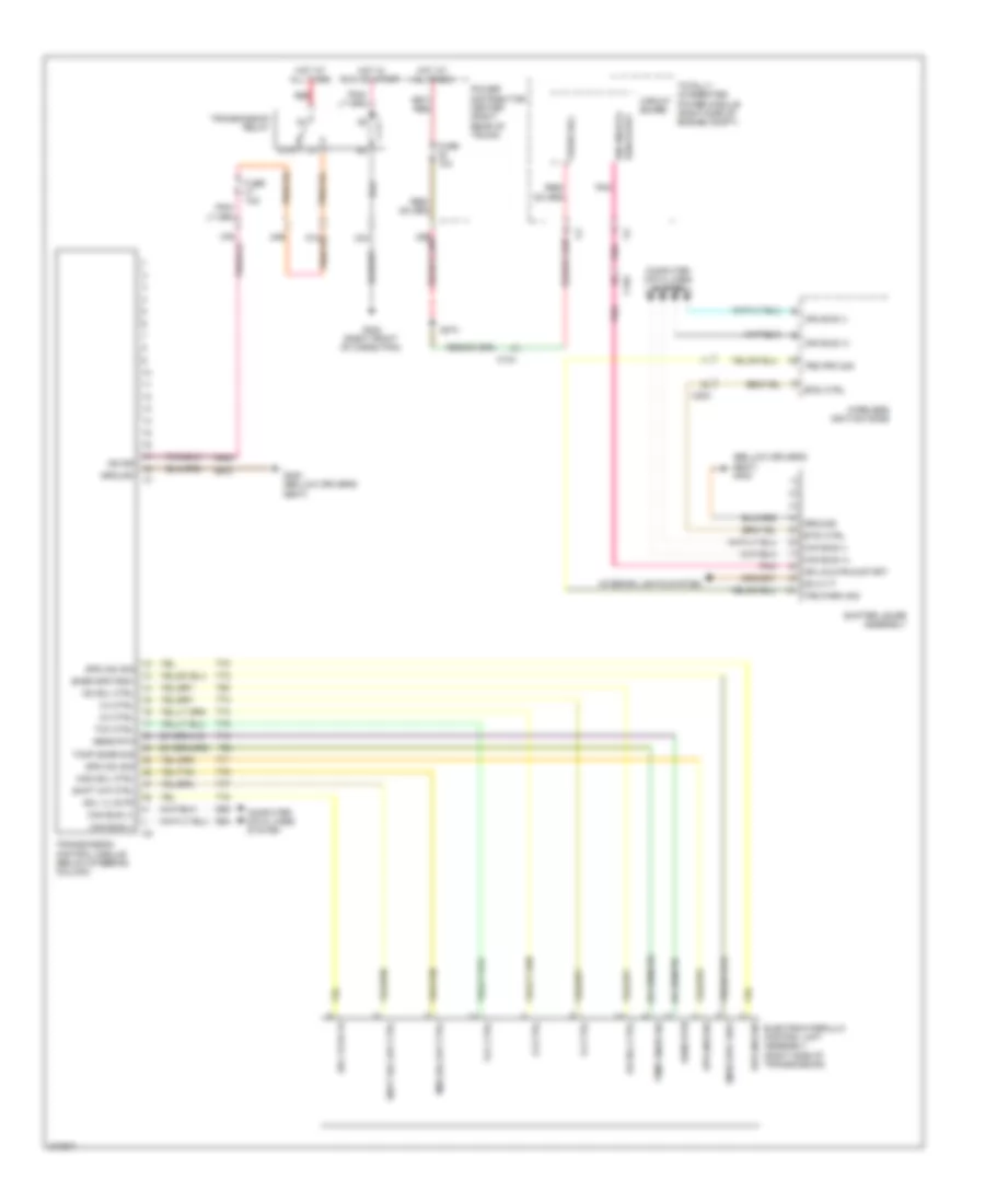
Radio Wiring Diagram (1 of 2) for Dodge Challenger SE 2010
List of elements for Radio Wiring Diagram (1 of 2) for Dodge Challenger SE 2010:
- 30b
- A300
- A913
- Amp ant feed
- Amplified ant feed
- Antenna sig/shld
- Batt fd
- C200
- C203
- C207
- C209
- Can b bus (+)
- Can b bus (-)
- Can bus (+)
- Can bus (-)
- Can bus b(+)
- Can bus b(-)
- Com audio out
- Com audio output
- Computer data lines system
- D106
- D126
- D500
- D501
- D502
- D54
- D55
- D64
- D65
- D931
- Fuse 10a
- Fused b(+)
- G200 (left side of dash)
- G202 (left side of dash)
- Ground
- Hands free module (right side of dash)
- Hot at all times
- Left audio out
- Left steering wheel switch
- Lh audio out
- Lin bus
- Lin lighting
- Lin slave feed
- Lin slave rtn
- Lr spkr (+)
- Lr spkr (-)
- Power distribution center (right rear of trunk)
- Radio
- Radio antenna (upper right backlight)
- Red
- Rh audio out
- Right audio out
- Right steering wheel switch
- Rmux rtn
- Rmux sig
- Rmux sig 2
- Rr spkr (+)
- Rr spkr (-)
- S307 (w/ subwoofer amplifier) (body floor, near passenger door)
- S309
- Sat ant sig/shld
- Satellite radio antenna (rear center of headliner)
- Steering control module (steering column)
- X51
- X52
- X57
- X58
- X62
- X703
- X704
- X795
- Z909
- Z910
Radio Wiring Diagram (2 of 2) for Dodge Challenger SE 2010
List of elements for Radio Wiring Diagram (2 of 2) for Dodge Challenger SE 2010:
- 36b
- A300
- Amp center i/p spkr (-)
- Amp lr spkr (+)
- Amp lr spkr (-)
- Amp lt i/p spkr (-)
- Amp rr spkr (+)
- Amp rr spkr (-)
- Amp rt i/p spkr (-)
- Amp subwoofer 1(+)
- Amp subwoofer 1(-)
- C200
- C203
- C300
- C301
- Can b bus (+)
- Can b bus (-)
- Center instrument panel speaker
- Comp fd
- Computer data lines system
- Ctr i/p spkr input (+)
- D54
- D55
- Fused b(+)
- G202 (left side of dash)
- G300 (below driver's seat)
- Ground
- Hot at all times
- Left front door speaker
- Left instrument panel speaker
- Left rear speaker
- Lf i/p spkr rtn (+)
- Lf spkr (+)
- Lf spkr (-)
- Lr spkr (+)
- Lr spkr (-)
- Power distribution center (right rear of trunk)
- Radio amplifier (left of dash)
- Rf i/p spkr fd (+)
- Rf spkr (+)
- Rf spkr (-)
- Right front door speaker
- Right instrument panel speaker
- Right rear speaker
- Rr spkr (+)
- Rr spkr (-)
- S203
- Sbfr 1 (+)
- Sbfr 1 (-)
- Sbfr 2 (+)
- Sbfr 2 (-)
- Sbfr sig (-)
- Subwoofer amplifier (if equipped)
- Subwoofer speaker
- W/ subwoofer amplifier
- W/o subwoofer amplifier
- X200
- X201
- X202
- X208
- X209
- X290
- X291
- X292
- X298
- X299
- X300
- X303
- X304
- X390
- X393
- X394
- X51
- X52
- X57
- X58
- Z910
SHIFT INTERLOCK
Shift Interlock Wiring Diagram for Dodge Challenger SE 2010
List of elements for Shift Interlock Wiring Diagram for Dodge Challenger SE 2010:
- (right rear of engine compt) powertrain control module
- 29b
- B15
- B16
- Brk sig 1
- Brk sig 2
- Btsi ctrl
- C104
- C203
- Can c bus +
- Can c bus -
- Circuit board
- Computer data lines system
- Ctrl out put
- D64
- D65
- E12
- E902
- F902
- Fuse 29 5a
- Fuse 8 15a
- Fused b (+)
- G300 (below driver's seat)
- Gnd
- Hot at all times
- Hot w/ run/ start relay energized
- Ign off- run-start
- Ign off-run-start
- Interior lights system
- K321
- Panel lamps drv
- Pnk
- Power distribution center (right rear of trunk)
- Power distribution system
- Red
- Run/start
- S215
- Shifter lever assembly
- Stop lamp switch (base of brake pedal)
- T824
- Totally integrated power module (right side of engine compt)
- Trs park sig
- Wireless ignition node
- Z912
STARTING/CHARGING
Charging Wiring Diagram for Dodge Challenger SE 2010
List of elements for Charging Wiring Diagram for Dodge Challenger SE 2010:
- A804
- B(+)
- Battery
- C100
- Can b bus(+)
- Can b bus(-)
- Can bus(+)
- Can bus(-)
- Cluster
- Computer data lines system
- D64
- D65
- G303 (near battery)
- Gen field ctrl
- Gen sens
- Generator
- K20
- Pass through post
- Power distribution system
- Powertrain control module (right rear of engine compt)
- Red
- S100 (3.5l: left rear of engine)
- S138
- S142
- Starter
Starting Wiring Diagram for Dodge Challenger SE 2010
List of elements for Starting Wiring Diagram for Dodge Challenger SE 2010:
- (a/t)
- 15a
- 3.5l
- 87a
- B(+)
- Battery
- Brake lamp control output
- Brk lp ctrl out
- Btsi control
- Btsi ctrl
- Bus bar
- C100
- C102
- C203
- Can c bus (+)
- Can c bus (-)
- Circuit board
- Clutch interlock sig
- Clutch interlock st ctrl
- Clutch interlock switch (m/t)
- Com-lin
- Computer data lines system
- D64
- D65
- Except 3.5l
- Exterior lights system
- Fuse
- Fuse 25a
- Fused b(+)
- G202 (left of dash)
- G303 (near battery)
- Generator
- Ground
- Hold-in
- Ign run- start output
- Ign run-start
- M/t
- Pass through post
- Power distribution center (right rear of trunk)
- Powertrain control module (right rear of engine compt)
- Pull-in
- Red
- Red a11
- S100
- S138
- S142
- S215
- S302
- Shifter lever assembly
- Starter
- Starter coil driver
- Starter relay
- Starter rly ctrl clutch interlock st ctrl c3
- T142
- T752
- Totally integrated power module (right side of engine compt)
- Trs park sig
- Wireless ignition node
SUPPLEMENTAL RESTRAINTS
Supplemental Restraints Wiring Diagram (1 of 2) for Dodge Challenger SE 2010
List of elements for Supplemental Restraints Wiring Diagram (1 of 2) for Dodge Challenger SE 2010:
- (not used)
- 27b
- 28b
- 30b
- Base tpm
- C102
- C203
- C300
- C314
- Can bus (+)
- Can bus (-)
- Can c bus (+)
- Can c bus (-)
- Cluster
- Computer data lines system
- D64
- D65
- Driver seat belt tensioner
- Driver seat belt tensioner line 1
- Driver seat belt tensioner line 2
- Driver seat position sens data
- Driver seat position sens voltage
- Driver seat track position sensor
- F201
- F500
- Fuse 10a
- G200a
- Gnd
- Hot at all times
- Hot in run
- Hot in run or start
- Left curtain squib 1 line 1
- Left curtain squib 1 line 2
- Left front impact sens gnd
- Left front impact sens sig
- Left front impact sensor (left front of engine compt)
- Left side curtain air bag
- Line 1
- Line 2
- Mirror switch
- Occupant restraint controller module (in center console)
- Passenger seat belt switch
- Passenger seat belt tensioner
- Passenger seat belt tensioner line 1
- Passenger seat belt tensioner line 2
- Power distribution center (right rear of trunk)
- Premium tpm
- R13
- R130
- R14
- R140
- R15
- R150
- R16
- R160
- R261
- R263
- R42
- R43
- R44
- R45
- R503
- R504
- R505
- R506
- R61
- R62
- R63
- R64
- R79
- R80
- R81
- R82
- Red
- Right curtain squib 1 line 1
- Right curtain squib 1 line 2
- Right front impact sens gnd
- Right front impact sens sig
- Right front impact sensor (right front of engine compt)
- Right side curtain air bag
- Rly output
- Run/start
- S210
- S310
- Sens 1 gnd
- Sens 1 sig
- Sens data
- Sens gnd
- Sens sig
- Sens voltage
- Squib 1 line 1
- Squib 1 line 2
- Squib 2 line 1
- Squib 2 line 2
- Tan
- Z939
Supplemental Restraints Wiring Diagram (2 of 2) for Dodge Challenger SE 2010
List of elements for Supplemental Restraints Wiring Diagram (2 of 2) for Dodge Challenger SE 2010:
- (in driver's door) left side impact pressure sensor
- (in passenger's door)
- (left "b" pillar) left side impact sensor 1
- (left of dash) g202
- (right "b" pillar) right side impact sensor 1
- A913
- C300
- C301
- Can b bus (+)
- Can b bus (-)
- Can c bus (+)
- Can c bus (-)
- Computer data lines system
- D54
- D55
- D64
- D65
- Driver air bag squib 1
- Driver air bag squib 2
- Driver squib 1 line 1
- Driver squib 1 line 2
- Driver squib 2 line 1
- Driver squib 2 line 2
- Fused b(+)
- Gnd
- Left side impact pressure sens gnd
- Left side impact pressure sens sig
- Left side impact sens 1 gnd
- Left side impact sens 1 sig
- Passenger air bag squib
- Pressure
- R43
- R45
- R61
- R63
- Right side impact
- Right side impact pressure sens sig
- Right side impact pressure sensor
- Right side impact sens 1 gnd
- Right side impact sens 1 sig
- Sens gnd
- Squib 1 line 1
- Squib 1 line 2
- Squib 2 line 1
- Squib 2 line 2
- Steering control module (steering column)
- Tan
- Z910
TRANSMISSION
Transmission Wiring Diagram for Dodge Challenger SE 2010
List of elements for Transmission Wiring Diagram for Dodge Challenger SE 2010:
- (bellow driver's seat) g300
- 2-3 ctrl
- 24b
- 3-4 ctrl
- 33a
- 37a
- 37b
- 87a
- Btsi ctrl
- C104
- C203
- Can bus (+)
- Can bus (-)
- Circuit board
- Computer data lines system
- D64
- D65
- Dim 31 p
- Electrohydraulic control unit assembly (right side of transmission)
- F942
- Fuse 10a
- Fuse 15a
- Fused b(+)
- G300 (bellow driver's seat)
- G302 (right front of cargo pan)
- G374
- Ground
- Hot at all times
- Hot in run or start
- Ign rs
- Ign unlk-run-start
- Ign unlock- run-start
- Interior lights system
- Mod sol /op ctrl
- Mod sol ctrl
- Od sol ctrl
- Pnk
- Power distribution center (right rear of trunk)
- Red
- Sens rtn
- Shift o/p ctrl
- Shift sol o/p ctrl
- Shifter lever assembly
- Snsr spd fd6v
- Sol vlvs fd
- Spd (n2) sig
- Spd (n3) sig
- T13
- T54
- T60
- T70
- T71
- T72
- T73
- T74
- T75
- T76
- T77
- T78
- Tcc ctrl
- Tcmp snsr sig
- Temp snsr sig
- Totally integrated power module (right side of engine compt)
- Transmission control module (below steering column)
- Transmission relay
- Trs park sig
- Trs prk sig
- Wireless ignition node
- Z912
TRUNK, TAILGATE, FUEL DOOR
Deck Lid Release Wiring Diagram for Dodge Challenger SE 2010
List of elements for Deck Lid Release Wiring Diagram for Dodge Challenger SE 2010:
- 14b
- Ajar switch sig
- C200
- Cargo lamp
- Cluster
- Decklid door latch
- Decklid release switch
- Decklid/ liftgate rel drv
- Fused b (+)
- G202 (left side of dash)
- G301 (below passenger's seat)
- G304 (next to deck lid latch)
- Gnd
- Hot at all times
- L gate sw sig
- Power distribution center (right rear of trunk)
- S200
WARNING SYSTEMS
Chime Wiring Diagram for Dodge Challenger SE 2010
List of elements for Chime Wiring Diagram for Dodge Challenger SE 2010:
- 14b
- B20
- Brake fluid level sensor (left rear of engine compt)
- Brake fluid level sig
- Brk lvl sw sig
- C200
- C203
- C300
- C301
- C313
- Can b bus (+)
- Can b bus (-)
- Can c bus (+)
- Can c bus(-)
- Circuit board
- Cluster
- Computer data lines system
- D64
- D65
- Decklid door latch
- Dk lid/lftgate ajar sw sens c1
- Driver door latch
- Driver door module
- Driver seat belt switch
- Drv dr ajar sw sense
- Drv dr secondary ajar sw sense
- Drv seat belt sw sense
- Fuse 10a
- Fused b (+)
- G100
- G202 (left side of dash)
- G300 (below driver's seat)
- G301 (below passengers seat)
- Gnd
- Ground
- Headlamp sw mux
- Headlamp sw mux rtn
- Headlamp switch
- Hot at all times
- Interior lights system
- Park brk sw sns
- Parking brake switch (base of parking brake)
- Pass dr ajar sw sense
- Pass dr secondary ajar sw sense
- Passenger door module
- Passengers door latch
- Power distribution center (right rear of trunk)
- S200
- S333 2912
- S355
- S360
- Tan
- Totally integrated power module (right side of engine compt)
Tire Pressure Monitoring Wiring Diagram for Dodge Challenger SE 2010
List of elements for Tire Pressure Monitoring Wiring Diagram for Dodge Challenger SE 2010:
- A913
- Can c bus (+)
- Can c bus (-)
- Computer data lines system
- D64
- D65
- Fuse 10a
- Fused b(+)
- G301 (below passenger's seat)
- Gnd
- Hot at all times
- Power distribution center (right rear of trunk)
- Red
- S309
- Tire pressure module (right rear wheel well)
- Z911
WIPER/WASHER
Wiper/Washer Wiring Diagram for Dodge Challenger SE 2010
List of elements for Wiper/Washer Wiring Diagram for Dodge Challenger SE 2010:
- (not used)
- (right side of engine compt) totally integrated power module
- 30b
- 38b
- 87a
- Batt fd
- C104
- C203
- Cab cmpt node batt fd
- Can b bus (+)
- Can b bus (-)
- Circuit board
- Cluster
- Computer data lines system
- D54
- D55
- Front washer fluid level sensor
- Front washer pump relay
- Front wiper motor (left rear of engine compt)
- Ft wpr wsh sig to bcm
- Ft wsh mtr ctrl
- Fuse 15a
- Fuse 30a
- Fused b(+)
- G100
- G101 (right front of engine compt)
- G102 (right of engine compt)
- G202 (left of dash)
- Gnd
- Ground distribution system
- Hot at all times
- Mtr ctrl
- Nca
- Park sw sen
- Power distribution center (right rear of trunk)
- Red
- Red/ a913
- Rly ctrl
- Rr wpe/wsh sig
- Rr wsh ctrl
- S309
- S374
- Steering control module (steering column)
- Sw sns
- Washer fluid lvl sw sns
- Windshield washer pump (right front of engine compt)
- Wiper hi spd ctrl out put
- Wiper high/low relay
- Wiper low spd ctrl out put
- Wiper on/off relay
- Wiper on/off relay control
- Wiper park sw sns

 Čeština
 Dansk
Dansk Deutsch
 Ελληνικά
 English
 English
 Español
 Suomi
Suomi Français
 Français
 עברית
עברית Hrvatski
 Magyar
 日本語
日本語 한국어
한국어 Nederlands
 Polski
 Português
 Português
 Română
 Русский
 Slovenčina
 Slovenščina
 Svenska
 Türkçe
 中文 (中国)