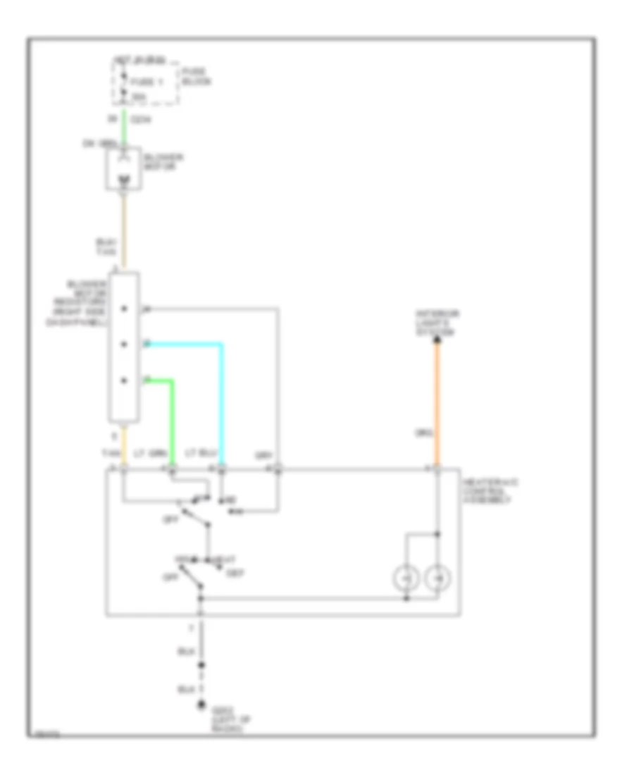
AIR CONDITIONING
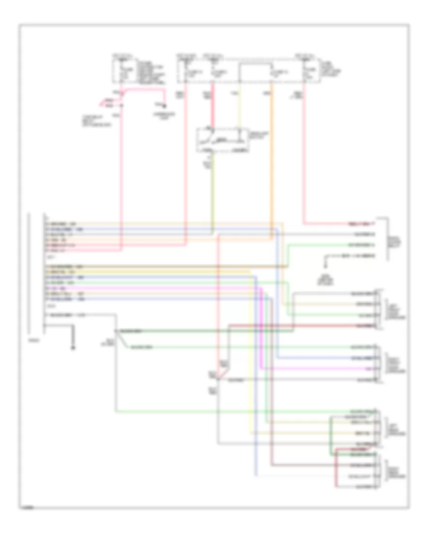
2.5L
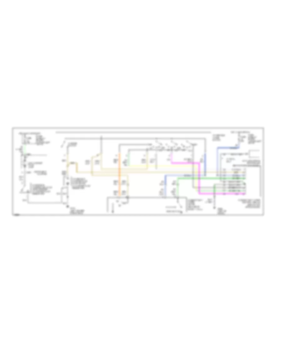
2.5L, A/C Wiring Diagram for Dodge Dakota 1996
 https://portal-diagnostov.com/license.html
Automotive Electricians Portal FZCO
Automotive Electricians Portal FZCO
https://portal-diagnostov.com/license.html
https://portal-diagnostov.com/license.html
Automotive Electricians Portal FZCO
Automotive Electricians Portal FZCO
List of elements for 2.5L, A/C Wiring Diagram for Dodge Dakota 1996:
- l
- (right fender side shield)
- 30a
- A/c
- A/c clutch
- A/c compressor clutch
- A/c compressor clutch relay (in power distribution center)
- A/c high pressure switch (on a/c line)
- A/c low pressure switch (on receiver/ dryer)
- A/c request
- A/c select input
- Acc
- Blower motor
- Blower motor resistor block (right side dash panel)
- C120
- C13
- C20
- C22
- C23
- C234
- C27
- C90
- Def
- Fan relay
- Fuse 1
- Fuse b
- Fuse block
- G105 (dash panel near resistor block)
- G202 (left of radio)
- Heat
- Heater-a/c control assembly
- Hi/lo
- Hot at all times
- Hot in run
- Ignition switch
- Interior lights system
- Max a/c
- Off
- Pnk
- Power distribution center
- Powertrain control module
- Radiator cooling fan motor
- Radiator fan control relay (in power distribution center)
- Relay
- Run
- Start
- Tan
Heater Wiring Diagram for Dodge Dakota 1996
List of elements for Heater Wiring Diagram for Dodge Dakota 1996:
- l
- 30a
- Blower motor
- Blower motor resistors (right side dash panel)
- C234
- Def
- Fuse 1
- Fuse block
- G202 (left of radio)
- Heat
- Heater-a/c control assembly
- Hi/lo
- Hot in run
- Interior lights system
- Off
- Tan
3.9L
3.9L, A/C Wiring Diagram for Dodge Dakota 1996
List of elements for 3.9L, A/C Wiring Diagram for Dodge Dakota 1996:
- l
- (right fender side shield)
- 30a
- A/c
- A/c clutch
- A/c compressor clutch
- A/c compressor clutch relay (in power distribution center)
- A/c high pressure switch (on a/c line)
- A/c low pressure switch (on receiver/ dryer)
- A/c request
- A/c select input
- Acc
- Blower motor
- Blower motor resistor block (right side dash panel)
- C120
- C13
- C20
- C22
- C23
- C234
- C90
- Def
- Fuse 1
- Fuse b
- Fuse block
- G105 (dash panel near resistor block)
- G202 (left of radio)
- Heat
- Heater-a/c control assembly
- Hi/lo
- Hot at all times
- Hot in run
- Ignition switch
- Interior lights system
- Max a/c
- Off
- Power distribution center
- Powertrain control module
- Relay
- Run
- Start
- Tan
Heater Wiring Diagram for Dodge Dakota 1996
List of elements for Heater Wiring Diagram for Dodge Dakota 1996:
- l
- 30a
- Blower motor
- Blower motor resistors (right side dash panel)
- C234
- Def
- Fuse 1
- Fuse block
- G202 (left of radio)
- Heat
- Heater-a/c control assembly
- Hi/lo
- Hot in run
- Interior lights system
- Off
- Tan
5.2L
5.2L, A/C Wiring Diagram for Dodge Dakota 1996
List of elements for 5.2L, A/C Wiring Diagram for Dodge Dakota 1996:
- l
- (right fender side shield)
- 30a
- A/c
- A/c clutch
- A/c compressor clutch
- A/c compressor clutch relay (in power distribution center)
- A/c high pressure switch (on a/c line)
- A/c low pressure switch (on receiver/ dryer)
- A/c request
- A/c select input
- Acc
- Blower motor
- Blower motor resistor block (right side dash panel)
- C120
- C13
- C20
- C22
- C23
- C234
- C90
- Def
- Fuse 1
- Fuse b
- Fuse block
- G105 (dash panel near resistor block)
- G202 (left of radio)
- Heat
- Heater-a/c control assembly
- Hi/lo
- Hot at all times
- Hot in run
- Ignition switch
- Interior lights system
- Max a/c
- Off
- Power distribution center
- Powertrain control module
- Relay
- Run
- Start
- Tan
Heater Wiring Diagram for Dodge Dakota 1996
List of elements for Heater Wiring Diagram for Dodge Dakota 1996:
- l
- 30a
- Blower motor
- Blower motor resistors (right side dash panel)
- C234
- Def
- Fuse 1
- Fuse block
- G202 (left of radio)
- Heat
- Heater-a/c control assembly
- Hi/lo
- Hot in run
- Interior lights system
- Off
- Tan
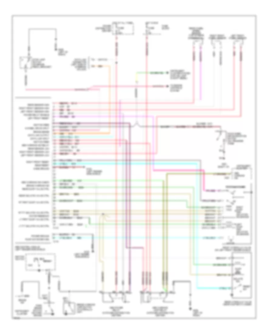
ANTI-LOCK BRAKES
All-Wheel ABS Wiring Diagram for Dodge Dakota 1996
List of elements for All-Wheel ABS Wiring Diagram for Dodge Dakota 1996:
- (right i/p)
- 4-wheel drive input
- A20
- Abs control module (left fender side shield)
- Abs power relay (in power distribution center)
- Abs warning ind
- Abs warning ind check
- Abs warning ind relay
- Abs warning lamp relay (in power distribution center)
- Acc
- B113
- B114
- B116
- B120
- B18
- B19
- B243
- B245
- B248
- B249
- B252
- B254
- B47
- B60
- Brake ind
- Brake sense
- Brake warning ind
- Brake warning lamp switch (in hydraulic unit)
- C118
- C119
- C221
- Case ground
- Cluster
- D11
- D12
- Data link connector (left side of steering column)
- Data link input
- Data link output
- Dump sol
- Four wheel drive indicator switch (on transfer case)
- Front hydraulic valve (on left front fender shield)
- Fuse 5a
- Fuse a 40a
- Fuse block
- G100 (left fender side shield)
- G102 (left fender side shield)
- G107
- G19
- G201
- G206 (left of radio)
- Hot at all times
- Hot in run
- Ignition feed
- Ignition switch
- Instrument
- Instrument cluster
- Instrument cluster system (4wd ind lamp in shift bezel)
- Isolate sol
- Left dump and isolation solenoids
- Left front reset
- Left front sensor high
- Left front sensor low
- Left front wheel sensor
- Lt frnt dump valve ctrl
- Lt ft isolate valve ctrl
- Motor
- Motor feedback
- Off
- Park brake switch (on park brake)
- Power distribution center
- Power ground
- Power relay enable
- Pump motor return
- Rear dump valve ctrl
- Rear hydraulic valve (near master cylinder)
- Rear isolate valve ctrl
- Rear reset
- Rear sensor high
- Rear sensor low
- Rear wheel speed sensor (top of rear differential)
- Red
- Reset sw
- Reset switches
- Right dump and isolation solenoids
- Right front reset
- Right front sensor high
- Right front sensor low
- Right front wheel sensor
- Rt frnt dump valve ctrl
- Rt ft isolate valve ctrl
- Run
- Start
- Stop lamp switch (on brake pedal bracket)
- To engine controls system
- V40
Rear Wheel ABS Wiring Diagram for Dodge Dakota 1996
List of elements for Rear Wheel ABS Wiring Diagram for Dodge Dakota 1996:
- (a/t)
- (m/t)
- 4-wheel drive input
- Abs warning ind
- Abs warning ind ctrl
- Acc
- B101
- B102
- B108
- B111
- B112
- B113
- B114
- Battery
- Brake sw input
- Brake warning lamp switch (on left frame rail)
- Bulb check
- C221
- C24
- Combination buzzer
- Data link connector (left side of steering column)
- Diode (taped in i/p harness)
- Dump sol
- Dump valve sol
- Exterior lights system (center mounted stop lamp)
- Exterior lights system (hazard flasher switch)
- F32
- Four wheel drive indicator switch (on transfer case)
- Fuse 10a
- Fuse 20a
- Fuse block
- G11
- G201 (right end of i/p)
- G201 (right i/p)
- G206 (left of radio)
- Ground
- Hot at all times
- Hot in run or start
- Ignition
- Ignition switch
- Instrument cluster
- Instrument cluster system (4wd ind lamp in shift bezel)
- Intermittent wiper control unit (under steering column)
- Isolate sol
- K29
- Off
- Park brake ind
- Park brake input
- Park brake switch (on park brake)
- Powertrain control module (right front fender apron)
- Rear isolate valve sol
- Rear wheel anti-lock control module (right kick panel)
- Rear wheel anti-lock sensor (top of rear axle)
- Reset
- Reset sw
- Run
- Rwal sensor
- Rwal valve (near master cylinder)
- Service data link
- Start
- Stop lamp switch (on brake pedal bracket)
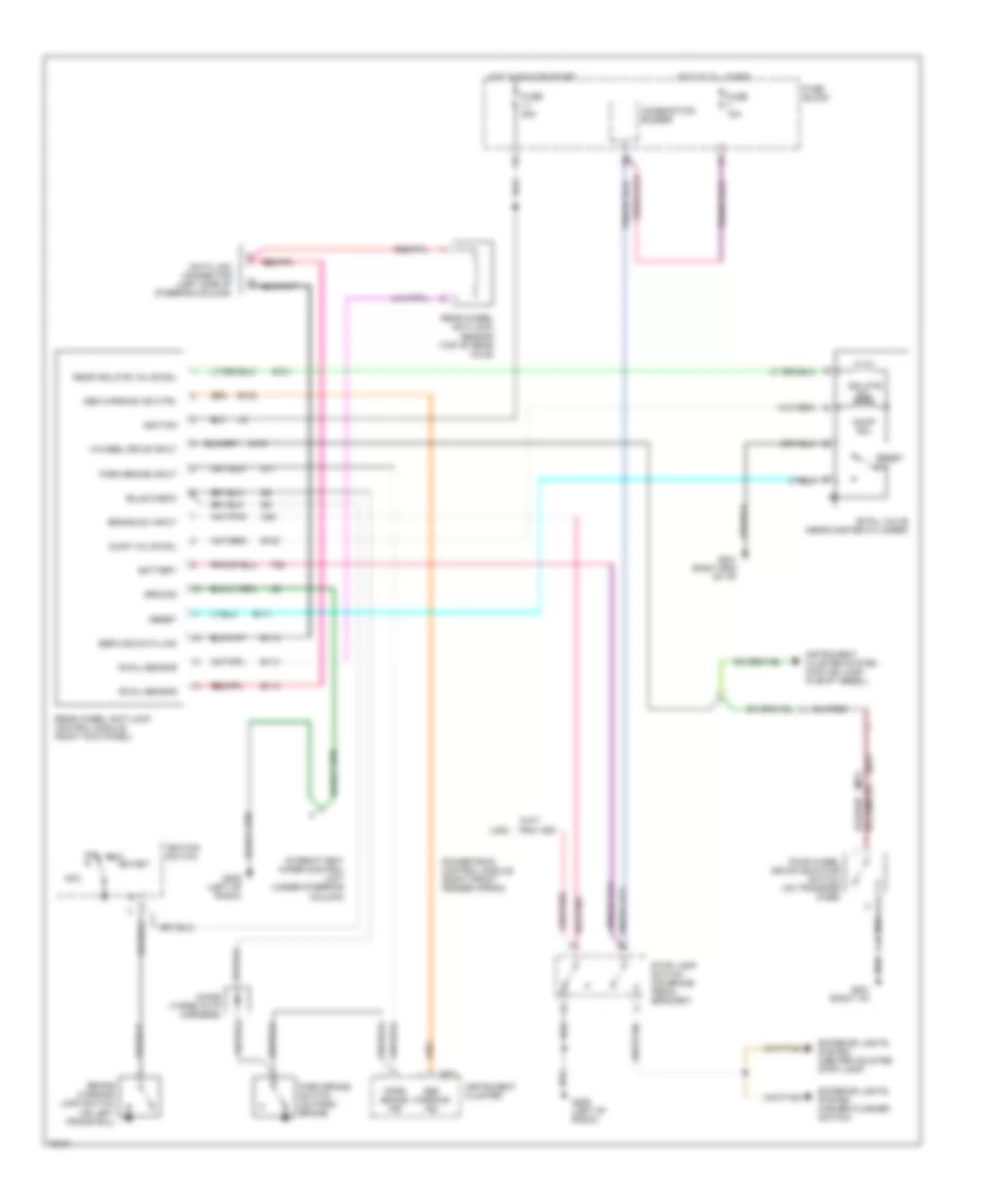
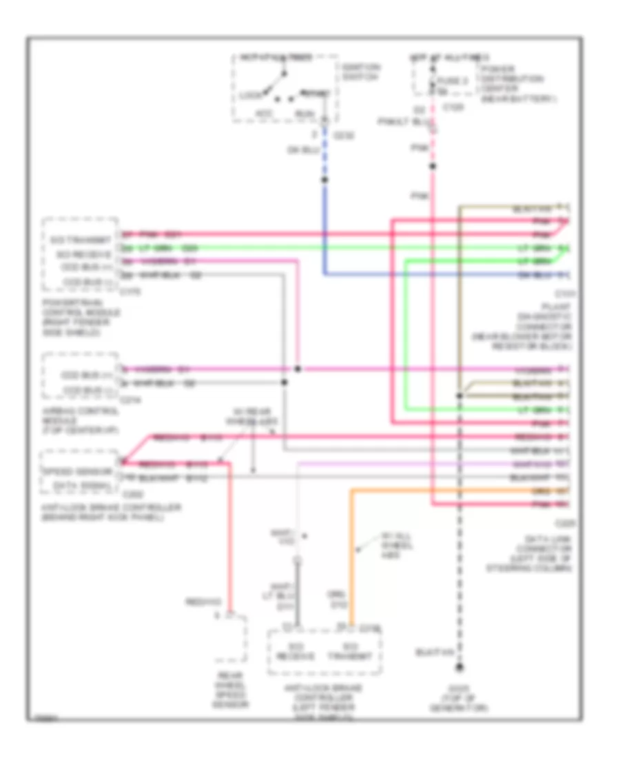
COMPUTER DATA LINES
Computer Data Lines for Dodge Dakota 1996
List of elements for Computer Data Lines for Dodge Dakota 1996:
- Acc
- Airbag control module (top center i/p)
- Anti-lock brake controller (behind right kick panel)
- Anti-lock brake controller (left fender side shield)
- B112
- B113
- C118
- C120
- C131
- C175
- C202
- C214
- C225
- C232
- Ccd bus (+)
- Ccd bus (-)
- D11
- D20
- D21
- Data link connector (left side of steering column)
- Data signal
- Fuse 2 5a
- G125 (top of generator)
- Hot at all times
- Ignition switch
- Lock
- Plant diagnostic connector (near blower motor resistor block)
- Pnk
- Power distribution center (near battery)
- Powertrain control module (right fender side shield)
- Rear wheel speed sensor
- Run
- Sci receive
- Sci transmit
- Speed sensor
- Start
- W/ all wheel abs
- W/ rear wheel abs
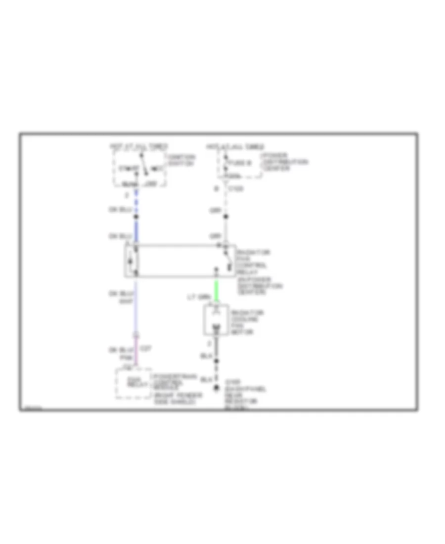
COOLING FAN
2.5L
2.5L, Cooling Fan Wiring Diagram for Dodge Dakota 1996
List of elements for 2.5L, Cooling Fan Wiring Diagram for Dodge Dakota 1996:
- (right fender side shield)
- 30a
- Acc
- C120
- C27
- Fan relay
- Fuse b
- G105 (dash panel near resistor block)
- Hot at all times
- Ignition switch
- Off
- Pnk
- Power distribution center
- Powertrain control module
- Radiator cooling fan motor
- Radiator fan control relay (in power distribution center)
- Run
- Start
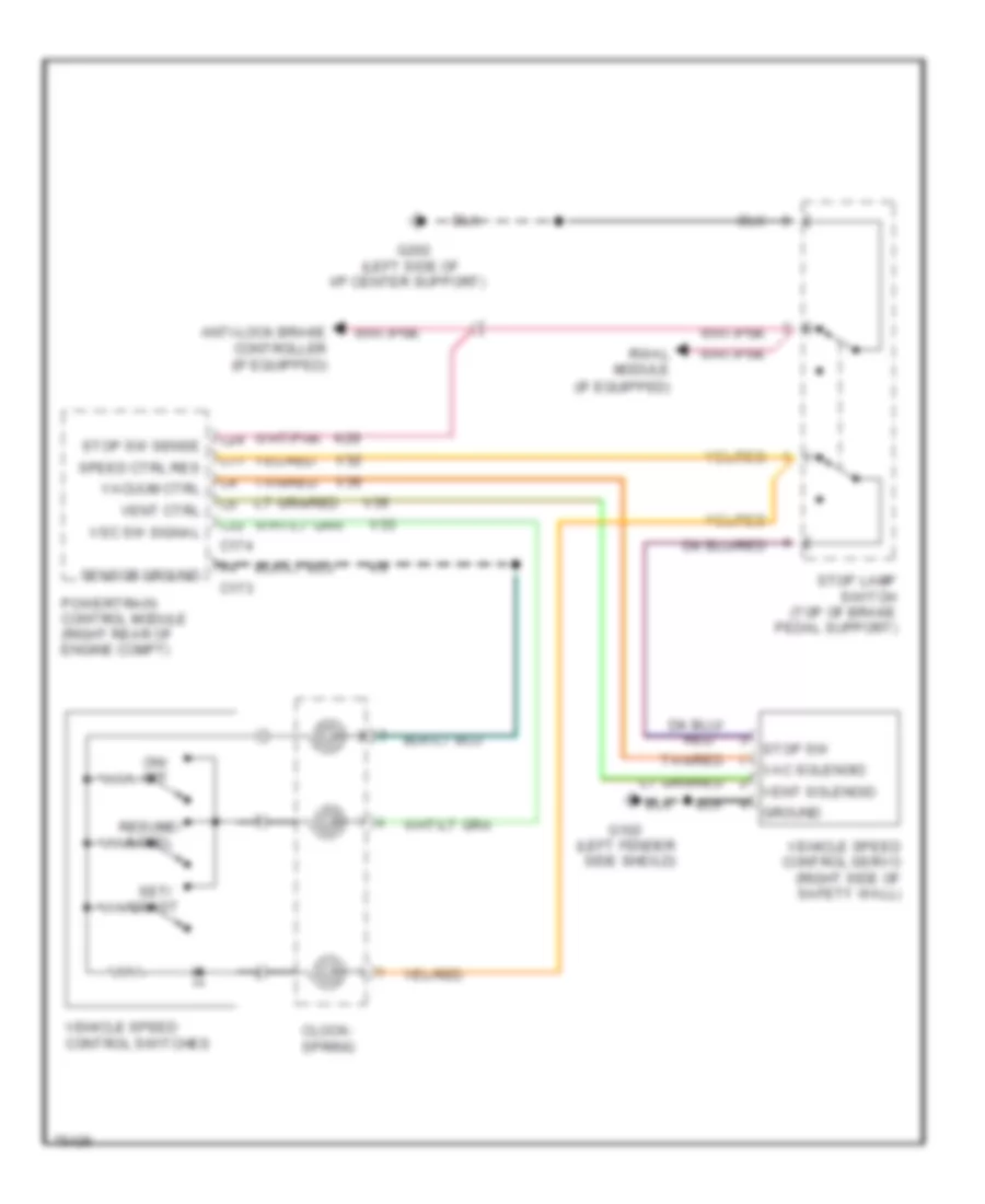
CRUISE CONTROL
Cruise Control Wiring Diagram for Dodge Dakota 1996
List of elements for Cruise Control Wiring Diagram for Dodge Dakota 1996:
- (left fender
- (left side of
- Anti-lock brake controller (if equipped)
- C11
- C173
- C174
- C24
- C32
- Clock- spring
- G102
- G202
- Ground
- I/p center support)
- K29
- On/ off
- Powertrain control module (right rear of engine compt)
- Red
- Resume/ accel
- Rwal module (if equipped)
- Sensor ground
- Set/ coast
- Side sheild)
- Speed ctrl res
- Stop lamp switch (top of brake pedal support)
- Stop sw
- Stop sw sense
- Tan/red
- V32
- V33
- V35
- V36
- Vac solenoid
- Vacuum ctrl
- Vehicle speed control servo (right side of safety wall)
- Vehicle speed control switches
- Vent ctrl
- Vent solenoid
- Vsc sw signal
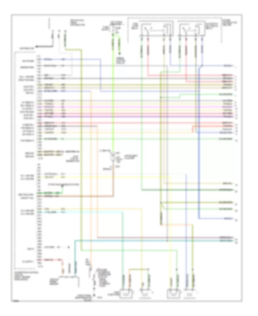
ENGINE PERFORMANCE
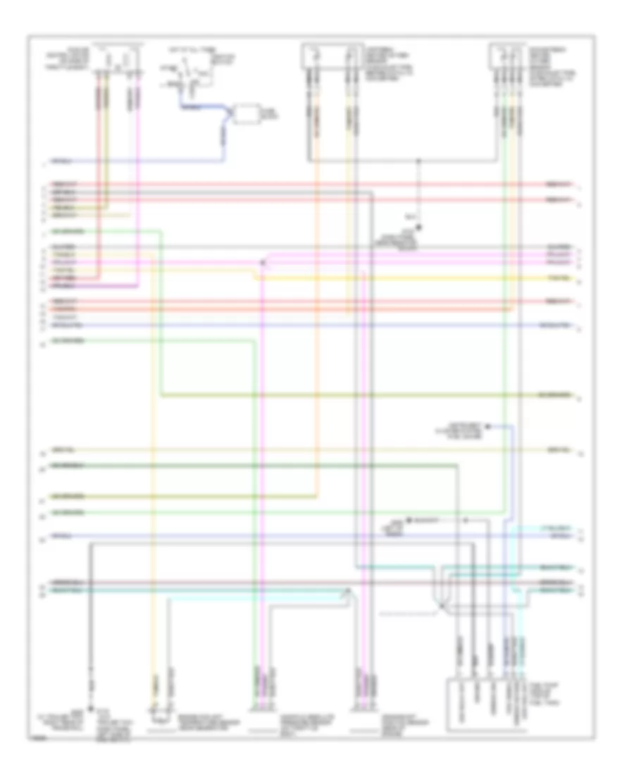
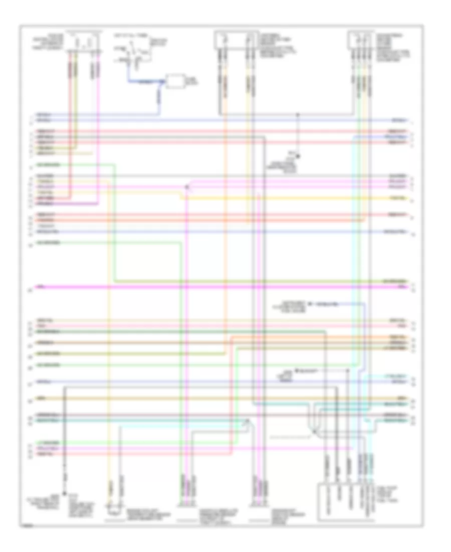
2.5L
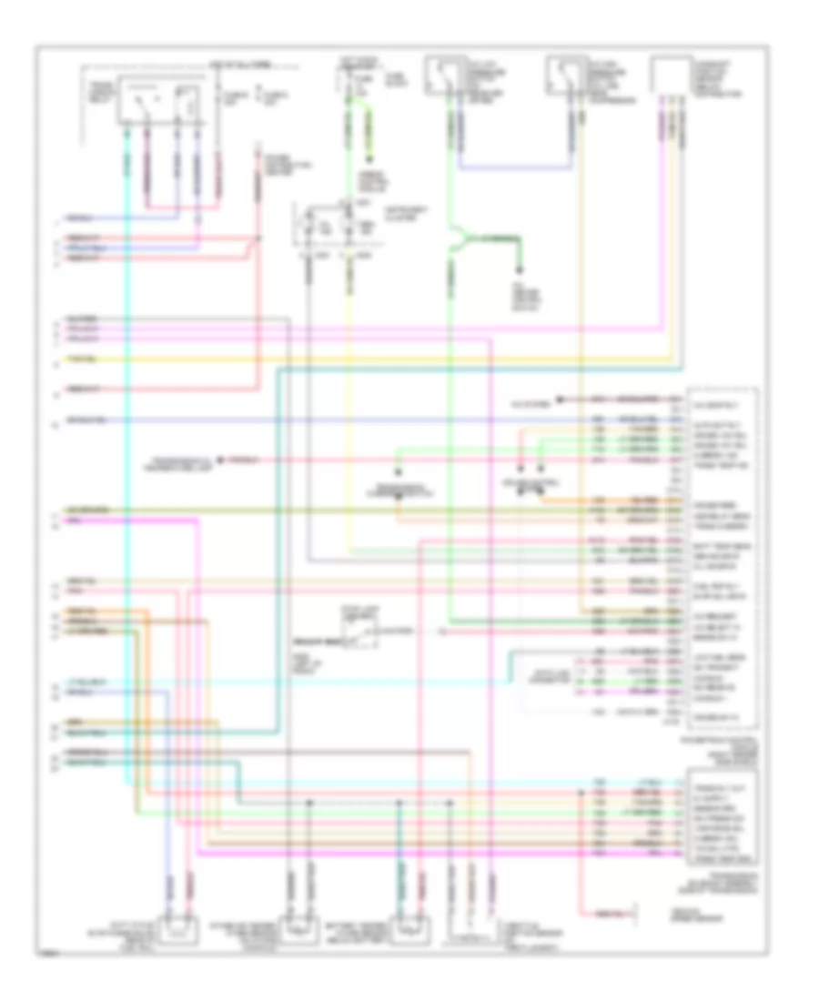
2.5L, Engine Performance Wiring Diagrams (1 of 3) for Dodge Dakota 1996
List of elements for 2.5L, Engine Performance Wiring Diagrams (1 of 3) for Dodge Dakota 1996:
- fused b(+) tps sens in up ho2s in
- gen field drv
- inj 1 driver inj 3 driver
- (dash panel, near resistor block)
- (top of
- A10
- A11
- A12
- A13
- A14
- A15
- A16
- A17
- A18
- A19
- A20
- A21
- A22
- A23
- A24
- A25
- A26
- A27
- A28
- A29
- A30
- A31
- A32
- Airbag control module
- Automatic shutdown relay
- B10
- B11
- B12
- B13
- B14
- B15
- B16
- B17
- B18
- B19
- B20
- B21
- B22
- B23
- B24
- B25
- B26
- B27
- B28
- B29
- B30
- B31
- B32
- Block
- C173
- C174
- C221
- Coil 1 driver
- Crnk pos sns
- Distributor
- Dn ho2s in
- Fuel injectors
- Fuel pump relay
- Fuse
- Fuse 15a
- G123
- G125
- Generator)
- Ground ground
- Hot in run or start
- Iat sens in
- Idle air 1 idle air 4
- Idle air 2
- Idle air 3 psp sw
- Ign power
- Ignition coil (near distributor)
- Inj 2 driver
- Inj 4 driver
- Instrument cluster
- K10
- K11
- K12
- K13
- K14
- K141
- K19
- K20
- K21
- K22
- K24
- K341
- K39
- K40
- K44
- K54
- K59
- K60
- Map sens in
- Nca
- Power distribution center
- Power steering pressure switch (near power steering pump)
- Powertrain control module (right fender side shield)
- Sensor grd
- Starting/charging system
- T33
- Tan
- Tan/pnk
- Up- shift ind.
- Upshift ind.
- Vehicle speed sensor
- Vss in
- Z12
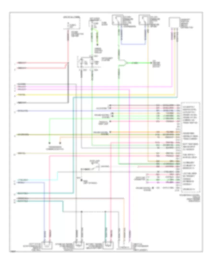
2.5L, Engine Performance Wiring Diagrams (2 of 3) for Dodge Dakota 1996
List of elements for 2.5L, Engine Performance Wiring Diagrams (2 of 3) for Dodge Dakota 1996:
- (dash panel, left side of master cyl)
- (dash panel, near resistor block)
- (w/o
- Acc
- Asd relay out
- C232
- Crankshaft position sensor (rear of engine)
- Downstream heated oxygen sensor (in exhaust pipe, after catalyic converter)
- Engine coolant temperature sensor (near generator)
- Fuel pump module (top of fuel tank)
- Fuel signal
- Fuse block
- G116
- G123
- G206 (left of radio)
- G405 (w/ trailer tow) (right rear of frame rail)
- Ground
- Hot at all times
- Idle air control motor (on side of throttle body)
- Ignition switch
- Instrument cluster system (fuel gauge)
- Low fuel out
- Manifold absolute pressure sensor (on throttle body)
- Nca
- Off
- Run
- Sensor grd
- Sensor return
- Start
- Tan/pnk
- Trailer tow)
- Upstream heated oxygen sensor (in exhaust pipe, before catalyic converter)
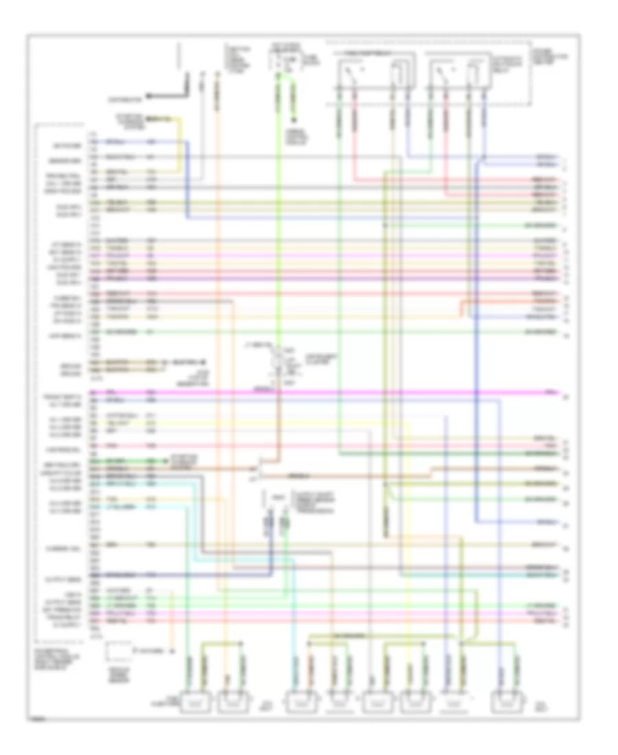
2.5L, Engine Performance Wiring Diagrams (3 of 3) for Dodge Dakota 1996
List of elements for 2.5L, Engine Performance Wiring Diagrams (3 of 3) for Dodge Dakota 1996:
- A/c comp rly
- A/c heater control switch
- A/c high pressure switch (a/c line, near compressor)
- A/c low pressure switch (on receiver dryer)
- A/c request
- A/c select in
- A/c system
- A142
- Airbag control module
- Asd relay sens
- Auto sht rly
- Batt temp sens
- Battery temper- ature sensor (below battery)
- Brake sw in
- C10
- C11
- C12
- C13
- C14
- C15
- C16
- C17
- C175
- C18
- C19
- C20
- C21
- C22
- C220
- C221
- C23
- C24
- C25
- C26
- C27
- C28
- C29
- C30
- C31
- C32
- C90
- Camshaft position sensor (below distributor)
- Ccd bus +
- Ccd bus -
- Cruise control system
- Cruise feed
- Cruise sw in
- Cruise vac sol
- Cruise vnt sol
- D20
- D21
- Data link connector
- Duty cycle/ evap purge solnd (rear of fuel rail)
- Evap sol drvr
- Fuel pmp rly
- Fuse 15a
- Fuse block
- Fuse d 30a
- G12
- G14
- G206 (left of radio)
- Gen ind drvr
- Gen. ind.
- Hot at all times
- Hot in run or start
- Instrument cluster
- Intake air temper- ature sensor (on intake manifold)
- K118
- K29
- K31
- K51
- K52
- Low fuel sens
- Mil ind drvr
- Mil ind.
- Overdrv ind
- Pnk
- Power distribution center
- Powertrain control module (right fender side shield)
- Rad fan cntrl
- Sci receive
- Sci transmit
- Stop lamp switch
- T18
- Tan/red
- Throttle position sensor (on throtlle body)
- Trans oil temp lamp
- Trans overdrv
- Trans temp ind
- Transmission overdrive switch
- V32
- V33
- V35
- V36
3.9L
3.9L, Engine Performance Wiring Diagrams (1 of 3) for Dodge Dakota 1996
List of elements for 3.9L, Engine Performance Wiring Diagrams (1 of 3) for Dodge Dakota 1996:
- fused b(+) tps sens in up ho2s in
- gen field drv
- inj 1 driver inj 3 driver inj 5 driver
- output sens
- overdrv sol
- trans temp in inj 7 driver
- var frce sol
- (top of
- 5.2l only
- A/t
- A10
- A11
- A12
- A13
- A14
- A15
- A16
- A17
- A18
- A19
- A20
- A21
- A22
- A23
- A24
- A25
- A26
- A27
- A28
- A29
- A30
- A31
- A32
- Airbag control module
- Automatic shutdown relay
- B10
- B11
- B12
- B13
- B14
- B15
- B16
- B17
- B18
- B19
- B20
- B21
- B22
- B23
- B24
- B25
- B26
- B27
- B28
- B29
- B30
- B31
- B32
- C173
- C174
- C221
- Coil 1 driver
- Crnk pos sns
- Distributor
- Dn ho2s in
- Fuel injectors
- Fuel pump relay
- Fuse 15a
- Fuse block
- G125
- Generator)
- Gov press sig
- Ground ground
- Hot in run or start
- Iat sens in
- Idle air 1 idle air 4
- Idle air 2
- Idle air 3
- Ign power
- Ignition coil (near distrib- utor)
- Inj 2 driver
- Inj 4 driver
- Inj 6 driver
- Inj 8 driver
- Instrument cluster
- K11
- K12
- K13
- K14
- K141
- K19
- K20
- K21
- K22
- K24
- K26
- K28
- K341
- K38
- K39
- K40
- K44
- K54
- K58
- K59
- K60
- M/t
- Map sens in
- Nca
- Output sens
- Output shaft speed sensor (side of transmission)
- Pnk
- Power distribution center
- Powertrain control module (right fender side shield)
- Prk/neutral
- Sensor grd
- Starting/ charging
- Starting/ charging system
- System
- T13
- T14
- T25
- T30
- T33
- T41
- T54
- T59
- T60
- Tan
- Tan/pnk
- Trans relay
- Up- shift ind.
- Upshift/tcc dr
- Vehicle speed sensor
- Vss in
- Z12
3.9L, Engine Performance Wiring Diagrams (2 of 3) for Dodge Dakota 1996
List of elements for 3.9L, Engine Performance Wiring Diagrams (2 of 3) for Dodge Dakota 1996:
- (dash panel, near resistor block)
- (w/o trailer tow) (dash panel, left side of master cyl)
- Acc
- Asd relay out
- C232
- Crankshaft position sensor (rear of engine)
- Downstream heated oxygen sensor (in exhaust pipe, after catalytic converter)
- Engine coolant temperature sensor (near generator)
- Fuel pump module (top of fuel tank)
- Fuel signal
- Fuse block
- G116
- G123
- G206 (left of radio)
- G405 (w/ trailer tow) (right rear of frame rail)
- Ground
- Hot at all times
- Idle air control motor (on rear of throttle body)
- Ignition switch
- Instrument cluster system (fuel gauge)
- Low fuel out
- Manifold absolute pressure sensor (on front of throttle body)
- Nca
- Off
- Pnk
- Run
- Sensor grd
- Sensor return
- Start
- Tan/pnk
- Upstream heated oxygen sensor (in exhaust pipe, before catalytic converter)
3.9L, Engine Performance Wiring Diagrams (3 of 3) for Dodge Dakota 1996
List of elements for 3.9L, Engine Performance Wiring Diagrams (3 of 3) for Dodge Dakota 1996:
- A/c comp rly
- A/c heater control switch
- A/c high pressure switch (a/c line, near compressor)
- A/c low pressure switch (on receiver dryer)
- A/c request
- A/c select in
- A/c system
- A142
- Airbag control module
- Asd relay sens
- Auto sht rly
- Batt temp sens
- Battery temper- ature sensor (below battery)
- Brake sw in
- C10
- C11
- C12
- C13
- C14
- C15
- C16
- C17
- C175
- C18
- C19
- C20
- C21
- C22
- C220
- C221
- C23
- C24
- C25
- C26
- C27
- C28
- C29
- C30
- C31
- C32
- C90
- Camshaft position sensor (below distributor)
- Ccd bus +
- Ccd bus -
- Cruise control system
- Cruise feed
- Cruise sw in
- Cruise vac sol
- Cruise vnt sol
- D20
- D21
- Data link connector
- Duty cycle/ evap purge solnd (rear of fuel rail)
- Evap sol drvr
- Fuel pmp rly
- Fuse 15a
- Fuse b 30a
- Fuse block
- Fuse d 30a
- G12
- G14
- G206 (left of radio)
- Gen ind drvr
- Gen. ind.
- Gov press sig
- Hot at all times
- Hot in run or start
- Instrument cluster
- Intake air temper- ature sensor (on intake manifold)
- K118
- K29
- K31
- K51
- K52
- K54
- Low fuel sens
- Mil ind drvr
- Mil ind.
- Overdrv ind
- Overdrv sol
- Pnk
- Power distribution center
- Powertrain control module (right fender side shield)
- Sci receive
- Sci transmit
- Sensor grd
- Stop lamp switch
- T18
- T20
- T25
- T33
- T35
- T54
- T59
- T60
- Tan/red
- Tcc sol ctrl
- Throttle position sensor (on throtlle body)
- Trans overdrv
- Trans rly out
- Trans temp ind
- Trans temp sns
- Trans- mission relay
- Transmission oil temperature lamp
- Transmission overdrive switch
- Transmission solenoid assembly (side of transmission)
- V32
- V33
- V35
- V36
- Var force sol
- Vehicle speed sensor
5.2L
5.2L, Engine Performance Wiring Diagrams (1 of 3) for Dodge Dakota 1996
List of elements for 5.2L, Engine Performance Wiring Diagrams (1 of 3) for Dodge Dakota 1996:
- fused b(+) tps sens in up ho2s in
- gen field drv
- inj 1 driver inj 3 driver inj 5 driver
- output sens
- overdrv sol
- trans temp in inj 7 driver
- var frce sol
- (top of
- 5.2l only
- A/t
- A10
- A11
- A12
- A13
- A14
- A15
- A16
- A17
- A18
- A19
- A20
- A21
- A22
- A23
- A24
- A25
- A26
- A27
- A28
- A29
- A30
- A31
- A32
- Airbag control module
- Automatic shutdown relay
- B10
- B11
- B12
- B13
- B14
- B15
- B16
- B17
- B18
- B19
- B20
- B21
- B22
- B23
- B24
- B25
- B26
- B27
- B28
- B29
- B30
- B31
- B32
- C173
- C174
- C221
- Coil 1 driver
- Crnk pos sns
- Distributor
- Dn ho2s in
- Fuel injectors
- Fuel pump relay
- Fuse 15a
- Fuse block
- G125
- Generator)
- Gov press sig
- Ground ground
- Hot in run or start
- Iat sens in
- Idle air 1 idle air 4
- Idle air 2
- Idle air 3
- Ign power
- Ignition coil (near distrib- utor)
- Inj 2 driver
- Inj 4 driver
- Inj 6 driver
- Inj 8 driver
- Instrument cluster
- K11
- K12
- K13
- K14
- K141
- K19
- K20
- K21
- K22
- K24
- K26
- K28
- K341
- K38
- K39
- K40
- K44
- K54
- K58
- K59
- K60
- M/t
- Map sens in
- Nca
- Output sens
- Output shaft speed sensor (side of transmission)
- Pnk
- Power distribution center
- Powertrain control module (right fender side shield)
- Prk/neutral
- Sensor grd
- Starting/ charging
- Starting/ charging system
- System
- T13
- T14
- T25
- T30
- T33
- T41
- T54
- T59
- T60
- Tan
- Tan/pnk
- Trans relay
- Up- shift ind.
- Upshift/tcc dr
- Vehicle speed sensor
- Vss in
- Z12
5.2L, Engine Performance Wiring Diagrams (2 of 3) for Dodge Dakota 1996
List of elements for 5.2L, Engine Performance Wiring Diagrams (2 of 3) for Dodge Dakota 1996:
- (dash panel, near resistor block)
- (w/o trailer tow) (dash panel, left side of master cyl)
- Acc
- Asd relay out
- C232
- Crankshaft position sensor (rear of engine)
- Downstream heated oxygen sensor (in exhaust pipe, after catalytic converter)
- Engine coolant temperature sensor (near generator)
- Fuel pump module (top of fuel tank)
- Fuel signal
- Fuse block
- G116
- G123
- G206 (left of radio)
- G405 (w/ trailer tow) (right rear of frame rail)
- Ground
- Hot at all times
- Idle air control motor (on rear of throttle body)
- Ignition switch
- Instrument cluster system (fuel gauge)
- Low fuel out
- Manifold absolute pressure sensor (on front of throttle body)
- Nca
- Off
- Pnk
- Run
- Sensor grd
- Sensor return
- Start
- Tan/pnk
- Upstream heated oxygen sensor (in exhaust pipe, before catalytic converter)
5.2L, Engine Performance Wiring Diagrams (3 of 3) for Dodge Dakota 1996
List of elements for 5.2L, Engine Performance Wiring Diagrams (3 of 3) for Dodge Dakota 1996:
- A/c comp rly
- A/c heater control switch
- A/c high pressure switch (a/c line, near compressor)
- A/c low pressure switch (on receiver dryer)
- A/c request
- A/c select in
- A/c system
- A142
- Airbag control module
- Asd relay sens
- Auto sht rly
- Batt temp sens
- Battery temper- ature sensor (below battery)
- Brake sw in
- C10
- C11
- C12
- C13
- C14
- C15
- C16
- C17
- C175
- C18
- C19
- C20
- C21
- C22
- C220
- C221
- C23
- C24
- C25
- C26
- C27
- C28
- C29
- C30
- C31
- C32
- C90
- Camshaft position sensor (below distributor)
- Ccd bus +
- Ccd bus -
- Cruise control system
- Cruise feed
- Cruise sw in
- Cruise vac sol
- Cruise vnt sol
- D20
- D21
- Data link connector
- Duty cycle/ evap purge solnd (rear of fuel rail)
- Evap sol drvr
- Fuel pmp rly
- Fuse 15a
- Fuse b 30a
- Fuse block
- Fuse d 30a
- G12
- G14
- G206 (left of radio)
- Gen ind drvr
- Gen. ind.
- Gov press sig
- Hot at all times
- Hot in run or start
- Instrument cluster
- Intake air temper- ature sensor (on intake manifold)
- K118
- K29
- K31
- K51
- K52
- K54
- Low fuel sens
- Mil ind drvr
- Mil ind.
- Overdrv ind
- Overdrv sol
- Pnk
- Power distribution center
- Powertrain control module (right fender side shield)
- Sci receive
- Sci transmit
- Sensor grd
- Stop lamp switch
- T18
- T20
- T25
- T33
- T35
- T54
- T59
- T60
- Tan/red
- Tcc sol ctrl
- Throttle position sensor (on throtlle body)
- Trans overdrv
- Trans rly out
- Trans temp ind
- Trans temp sns
- Trans- mission relay
- Transmission oil temperature lamp
- Transmission overdrive switch
- Transmission solenoid assembly (side of transmission)
- V32
- V33
- V35
- V36
- Var force sol
- Vehicle speed sensor
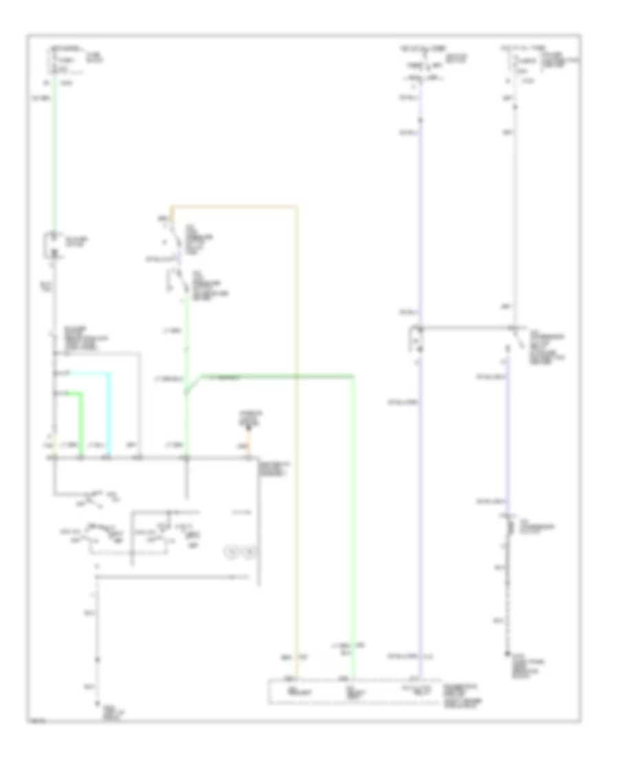
EXTERIOR LIGHTS
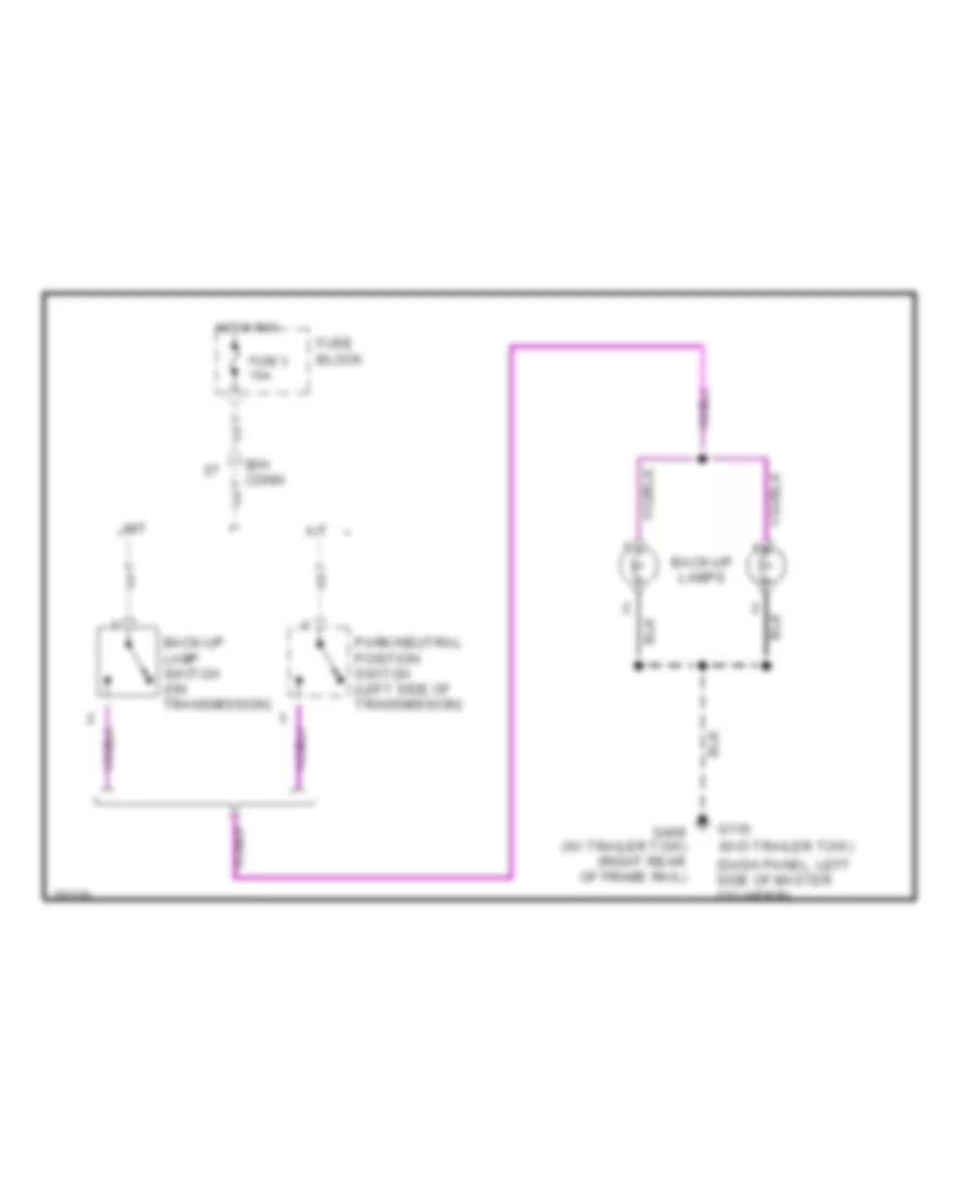
Back-up Lamps Wiring Diagram for Dodge Dakota 1996
List of elements for Back-up Lamps Wiring Diagram for Dodge Dakota 1996:
- (dash panel, left side of master cylinder)
- A/t
- B/h conn
- Back-up lamp switch (on transmission)
- Back-up lamps
- Fuse 3 15a
- Fuse block
- G116 (w/o trailer tow)
- G409 (w/ trailer tow) (right rear of frame rail)
- Hot in run
- M/t
- Park/neutral position switch (left side of transmission)
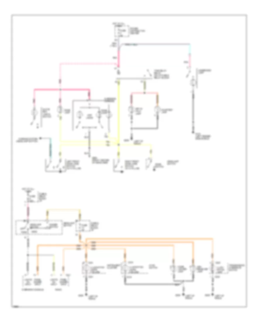
Exterior Lamps Wiring Diagram for Dodge Dakota 1996
List of elements for Exterior Lamps Wiring Diagram for Dodge Dakota 1996:
- (dash panel, near resistor block)
- (left fender side shield)
- (right rear of frame rail) g409
- (w/ trailer tow)
- (w/o trailer tow)
- B/h conn
- Back-up
- Back-up lamps system
- Body ground
- Brake switch (on bracket)
- Bumper
- C120
- C220
- C221 instrument cluster
- C234
- Center high- mount stop lamps
- Fuse 1 20a
- Fuse 11 20a
- Fuse 7 10a
- Fuse 8 20a
- Fuse block
- G104
- G116 (dash panel, left side of master cylinder)
- G123
- G206 (left of radio)
- Hazard
- Hazard flasher (mounted in fuse & relay block)
- Hazard switch
- Head
- Headlamp switch
- Hot at all times
- Hot in accy or run
- Left park & turn signal lamp
- Left tail/ stop & turn signal lamp
- Left turn & stop
- Left turn indicator
- License lamps
- Marker lamps
- Multi- function switch (on steering column)
- Normal
- Off
- Park
- Pnk
- Pnk/red
- Power distribution center
- Right park & turn signal lamp
- Right tail/ stop & turn signal lamp
- Right turn & stop
- Right turn indicator
- Tail light
- Tan
- Trailer tow wiring unterminated (if equipped)
- Turn signal flasher (mounted in fuse & relay block)
- Turn signal switch
- W/ step
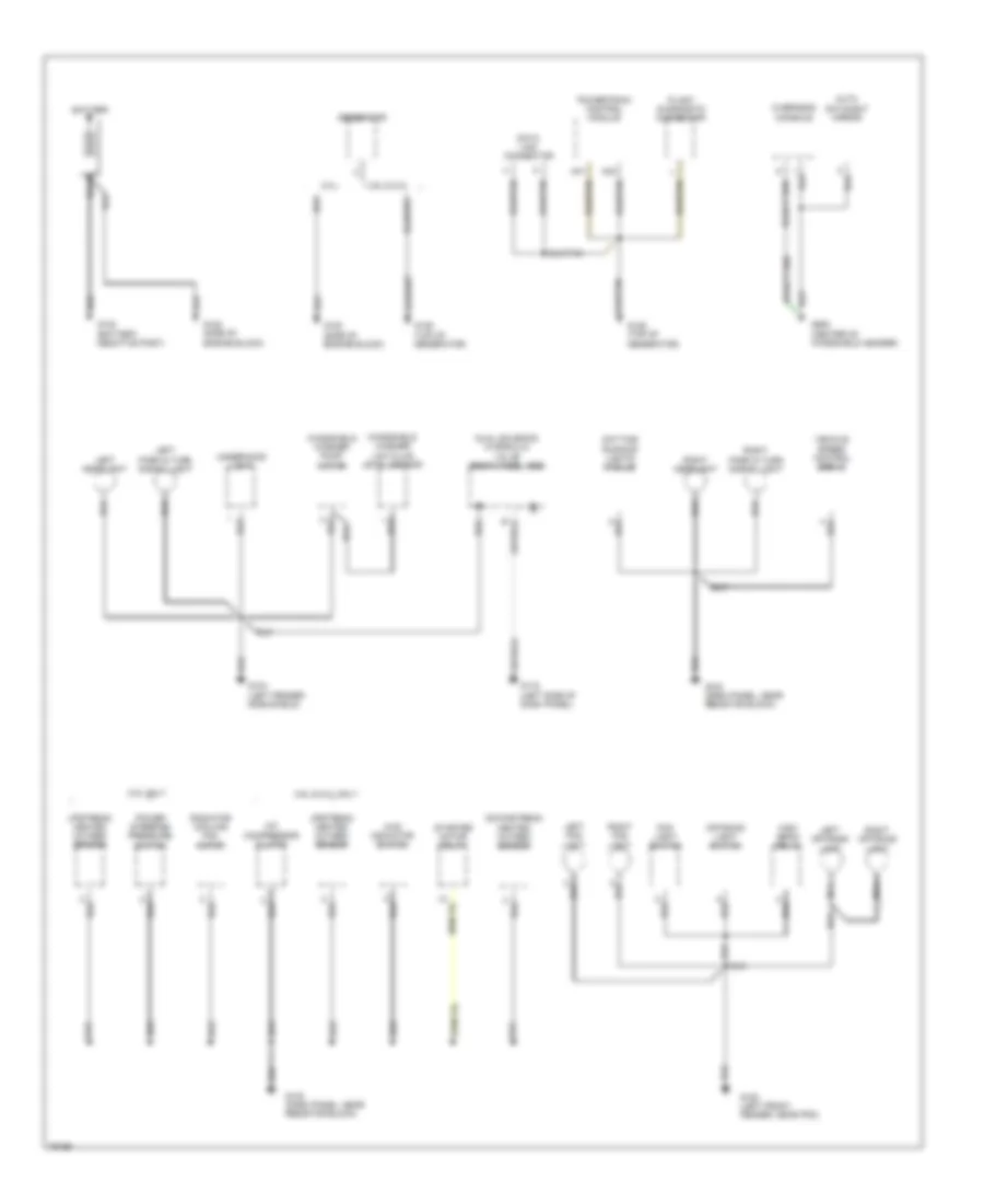
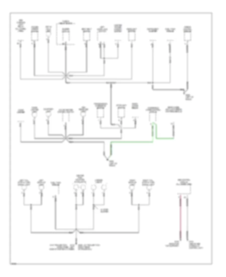
GROUND DISTRIBUTION
Ground Distribution Wiring Diagram (1 of 2) for Dodge Dakota 1996
List of elements for Ground Distribution Wiring Diagram (1 of 2) for Dodge Dakota 1996:
- (side of engine block)
- (top of generator)
- 2.5 l
- 2.5l only
- 3.9l & 5.2l
- 3.9l & 5.2l only
- 4wd indicator switch
- A/c compressor clutch
- A31
- A32
- Auto day/night mirror
- Battery
- Data link connector
- Daytime running lights module
- Downstream heated oxygen sensor
- Dual solenoid hydraulic valve (rear wheel abs)
- Fog light switch
- G100 (left front fender, near pdc)
- G104 (left fender side shield)
- G116 (left side of dash panel)
- G120
- G120 (side of engine block)
- G123 (dash panel, near resistor block)
- G125
- G125 (top of generator)
- G908 (center of windshield header)
- Generator
- High beam relay
- Left fog light
- Left headlight
- Left off-road light
- Left park & turn signal light
- Nca
- Off-road light switch
- Overhead console
- Plant diagnostic connector
- Power steering pressure switch
- Powertrain control module
- Radiator cooling fan motor
- Right fog light
- Right headlight
- Right off-road light
- Right park & turn signal light
- Starter motor relay
- Underhood light
- Upstream heated oxygen sensor
- Vehicle speed control servo
- Windshield washer low fluid level sensor
- Windshield washer pump motor
Ground Distribution Wiring Diagram (2 of 2) for Dodge Dakota 1996
List of elements for Ground Distribution Wiring Diagram (2 of 2) for Dodge Dakota 1996:
- (w/ trailer tow)
- (w/o trailer tow)
- A/c or heater control switch
- Abs control module (all wheel abs)
- Abs warning light relay (all-wheel abs)
- Airbag control module
- Ash receiver light
- Buzzer module
- Center high mounted stoplights
- Cigar lighter
- Cigar lighter light
- Courtesy light
- Fuel tank module
- Fuse & relay block
- G104 (above abs hydraulic control unit)
- G108 (radiator top support)
- G116 (dash panel, left side of master cylinder)
- G206 (left of radio)
- G409 (right rear of frame rail)
- Headlight switch
- Instrument cluster
- Key-in halo light
- Left back-up light
- Left door lock switch
- Left tail, stop & turn signal light
- License lights
- Master power window switch
- Power mirror switch
- Radio choke relay
- Rear wheel anti-lock break control module
- Right back-up light
- Right tail, stop & turn signal light
- Seat belt switch
- Stoplight switch
- Transmission overdrive switch
- W/ step bumper
- Windshield wiper control module
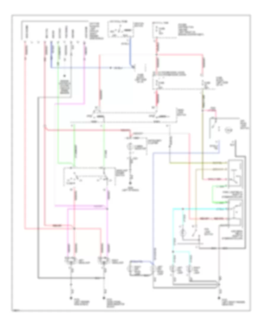
HEADLIGHTS
Headlamps/Fog Lamps/Off-Road Lamps Wiring Diagram, with DRL for Dodge Dakota 1996
List of elements for Headlamps/Fog Lamps/Off-Road Lamps Wiring Diagram, with DRL for Dodge Dakota 1996:
- A21
- Acc
- Battery
- C220
- C221
- Daytime running lamp module (right fender side shield)
- Engine controls system (vehicle speed sensor)
- Flash
- Fog lamp switch
- Fuse 20a
- Fuse 25a
- Fuse block (left side of i/p)
- Fuse g 50a
- G100 (left fender side shield)
- G100 (left front fender, near pdc)
- G123 (dash panel, near resistor block)
- G206 (left of radio)
- G34
- Ground
- Head
- Head- lamp switch
- Headlamp dimmer switch
- Hi beam indicator
- High beam relay (right of steering column)
- High beams
- Hot at all times
- Ign sw
- Ignition switch
- Ind ctrl
- Instrument cluster
- L20
- Left fog lamp
- Left headlamp
- Left off- road lamp
- Low beam
- Off
- Off- road lamp switch
- Park
- Park lamp relay (right of steering column)
- Pnk/red b2
- Power distribution center (left front of engine compartment)
- Right fog lamp
- Right headlamp
- Right off- road lamp
- Run
- Start
- Vss signal
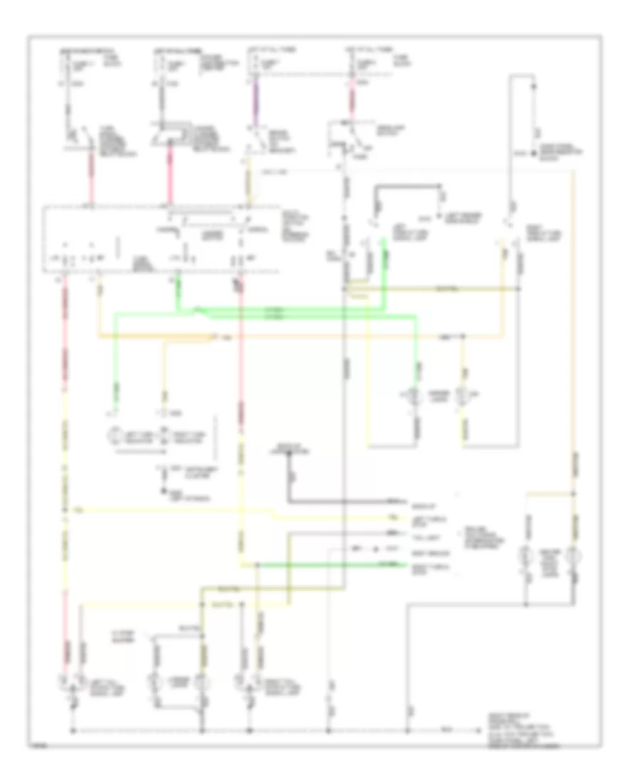
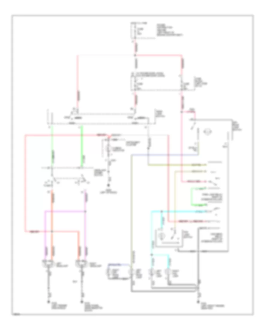
Headlamps/Fog Lamps/Off-Road Lamps Wiring Diagram, without DRL for Dodge Dakota 1996
List of elements for Headlamps/Fog Lamps/Off-Road Lamps Wiring Diagram, without DRL for Dodge Dakota 1996:
- C220
- C221
- Flash
- Fog lamp switch
- Fuse 20a
- Fuse 25a
- Fuse block (left side of i/p)
- Fuse g 50a
- G100 (left fender side shield)
- G100 (left front fender, near pdc)
- G123 (dash panel, near resistor block)
- G206 (left of radio)
- Head
- Head- lamp switch
- Headlamp dimmer switch
- Hi beam indicator
- High beam relay (right of steering column)
- Hot at all times
- Instrument cluster
- Left fog lamp
- Left headlamp
- Left off- road lamp
- Off
- Off- road lamp switch
- Park
- Park lamp relay (right of steering column)
- Pnk/red b2
- Power distribution center (left front of engine compartment)
- Right fog lamp
- Right headlamp
- Right off- road lamp
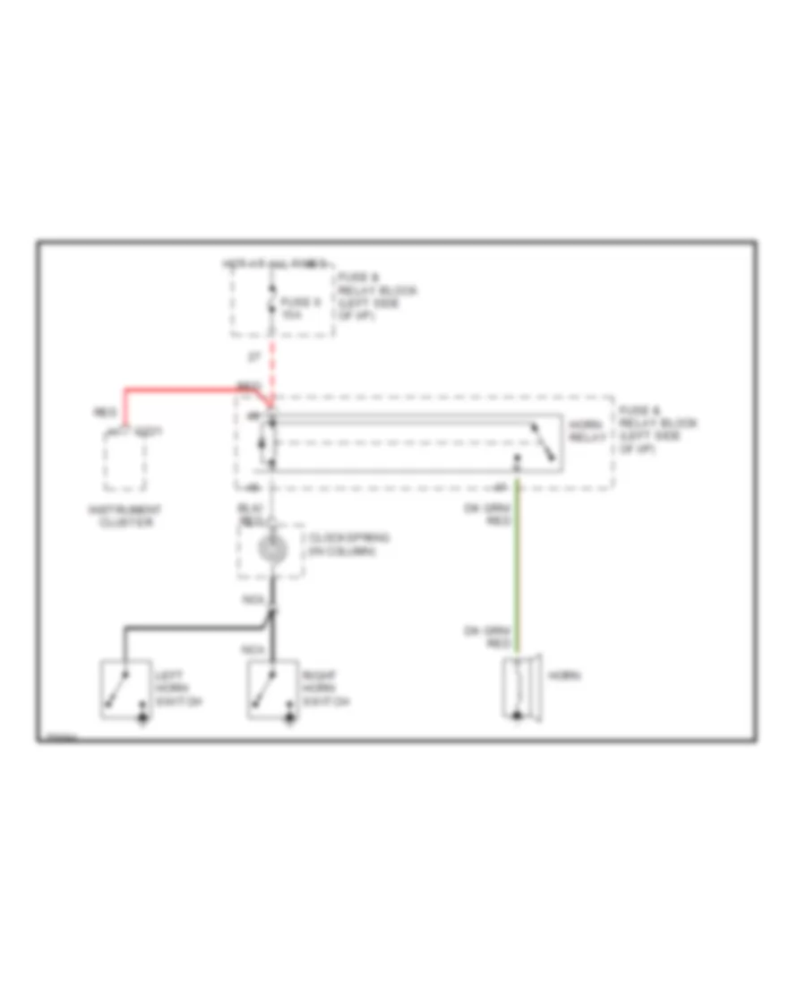
HORN
Horn Wiring Diagram for Dodge Dakota 1996
List of elements for Horn Wiring Diagram for Dodge Dakota 1996:
- C221
- Clockspring (in column)
- Fuse & relay block (left side of i/p)
- Fuse 6 15a
- Horn
- Horn relay
- Hot at all times
- Instrument cluster
- Left horn switch
- Nca
- Red
- Right horn switch
INSTRUMENT CLUSTER
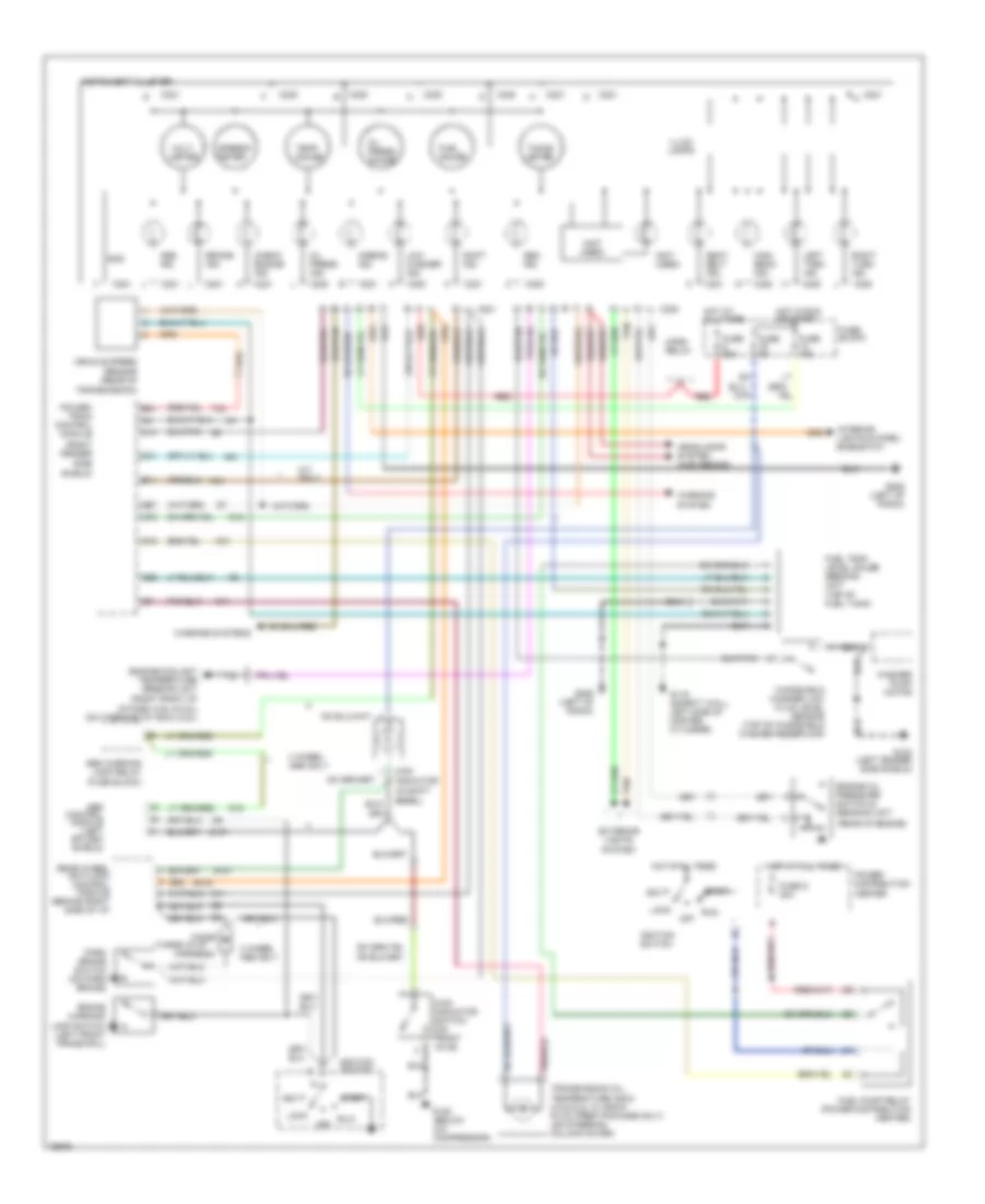
Instrument Cluster Wiring Diagram for Dodge Dakota 1996
List of elements for Instrument Cluster Wiring Diagram for Dodge Dakota 1996:
- (in shift
- (not used)
- (rear of engine)
- (right fender
- (right front of
- (taped in i/p
- 4 wheel abs only
- 4wd indicator
- 4wd indicator switch (on front axle)
- Abs control module (left splash shield)
- Abs ind.
- Abs warning lamp relay (fuse block)
- Acc
- Airbag ind.
- B102
- B11
- B27
- B31
- Bezel)
- Brake ind.
- Brake warning
- C16
- C17
- C19
- C220
- C221
- C26
- C31
- Check engine ind.
- Diode
- Engine coolant temperature sending unit
- Engine oil pressure switch & sending unit
- Exterior lights system
- Fuel gauge
- Fuel pump relay (power distribution center)
- Fuel tank level gauge sending unit (top of fuel tank)
- Fuse 15a
- Fuse 20a
- Fuse 5a
- Fuse block
- Fuse d 30a
- G100 (left fender side shield)
- G107
- G11
- G116 (safety wall, left side of master cylinder)
- G12
- G125 (below a/c compressor)
- G14
- G19
- G206 (left of radio)
- G21
- Gen. ind.
- Gnd
- Harness)
- Headlamps system (high beams)
- High beam ind.
- Horn relay
- Hot at all times
- Hot in run or start
- Ignition switch
- Illum. lamps
- Instrument cluster
- Intake) (3.9l & 5.2l) (on thermostat box) (2.5l)
- Interior lights system (rheostat)
- K31
- K54
- Lamp switch (left front frame rail)
- Left turn ind.
- Lock
- Low washer ind.
- M/t only
- Off
- Oil press. gauge
- Oil press. ind.
- Park brake switch (on park brake)
- Power distribution center
- Power- train control module
- Rear wheel anti-lock control module (behind right side of i/p)
- Red
- Right turn ind.
- Run
- Seat belt ind.
- Shift ind.
- Side shield)
- Speedo- meter
- Start
- T33
- Tacho- meter
- Tan
- Temp. gauge
- Transmission oil temperature indic. (3.9 & 5.2l w/ snow plow prep package only) (on steering column cover)
- Transmission)
- Vehicle speed sensor (rear of
- Volt- meter
- Warning system
- Warning systems
- Washer pump motor
- Windshield washer low fluid level sensor (top of windshield washer reservoir)
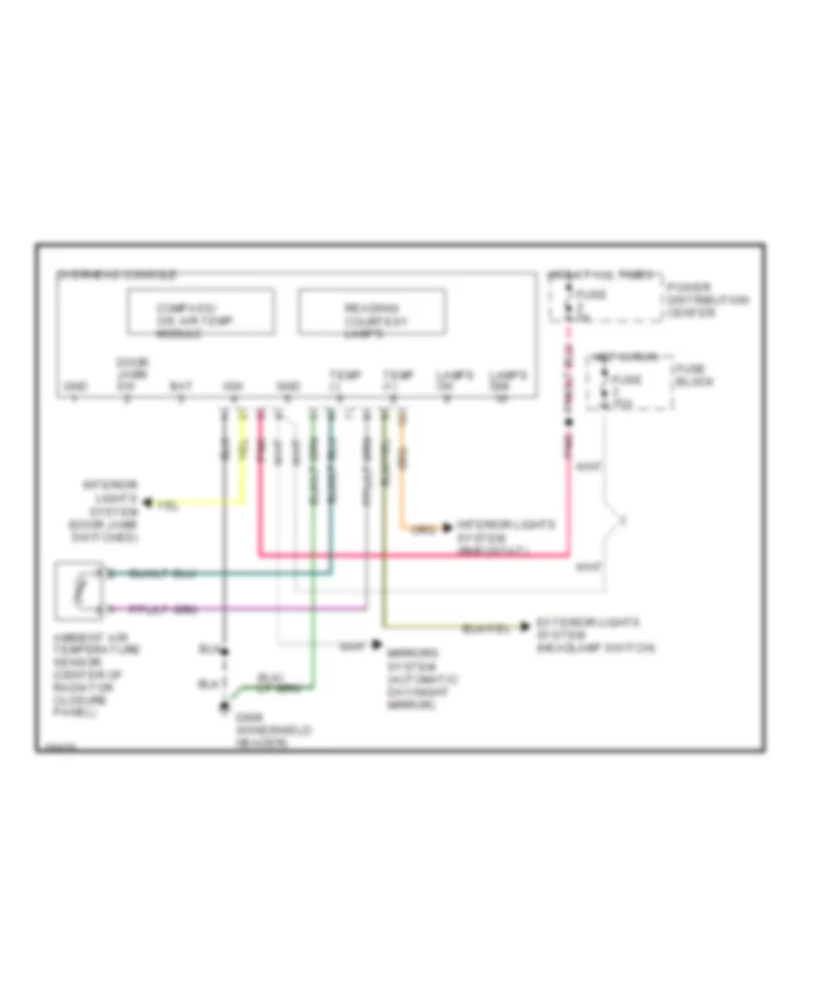
Overhead Console Wiring Diagram for Dodge Dakota 1996
List of elements for Overhead Console Wiring Diagram for Dodge Dakota 1996:
- Ambient air temperature sensor (center of radiator closure panel)
- Bat
- Compass/ o/s air temp. module
- Door jamb sw
- Exterior lights system (headlamp switch)
- Fuse 15a
- Fuse 5a
- Fuse block
- G908 (windshield header)
- Gnd
- Hot at all times
- Hot in run
- Ign
- Interior lights system (door jamb switches)
- Interior lights system (rheostat)
- Lamps dim
- Lamps on
- Mirrors system (automatic day/night mirror)
- Overhead console
- Pnk
- Power distribution center
- Reading/ courtesy lamps
- Temp (+)
- Temp (-)
INTERIOR LIGHTS
Interior Light Wiring Diagram for Dodge Dakota 1996
List of elements for Interior Light Wiring Diagram for Dodge Dakota 1996:
- (left of radio)
- Ash receiver lamp
- C211
- C216
- C221
- C223
- Cigar lighter lamp
- Courtesy lamp
- Dimmer switch
- Dome lamp
- Dome switch
- Fuse & relay block: i/p
- Fuse 20a
- Fuse 4a
- Fuse 5a
- G104 (left fender side shield)
- G206
- G908 (front center of headliner)
- Glove box lamp & switch
- Head
- Headlamp switch
- Hot at all times
- Hvac switch
- Illumi- nation lamp
- Illumination lamps (2 bulbs)
- Illumination lamps (7 bulbs)
- Instrument cluster
- Key-in halo lamp
- Left front door jamb switch (in "a" pillar)
- Lights on input
- Map lamps
- Off
- Overhead console
- Panel dimmer input
- Park
- Pnk
- Pnk/red
- Power distribution center
- Radio
- Right front door jamb switch (in "a" pillar)
- Tan
- Time delay relay (on i/p fuse & relay block)
- Transmission overdrive switch
- Underhood lamp
- Warning system (headlamp switch)
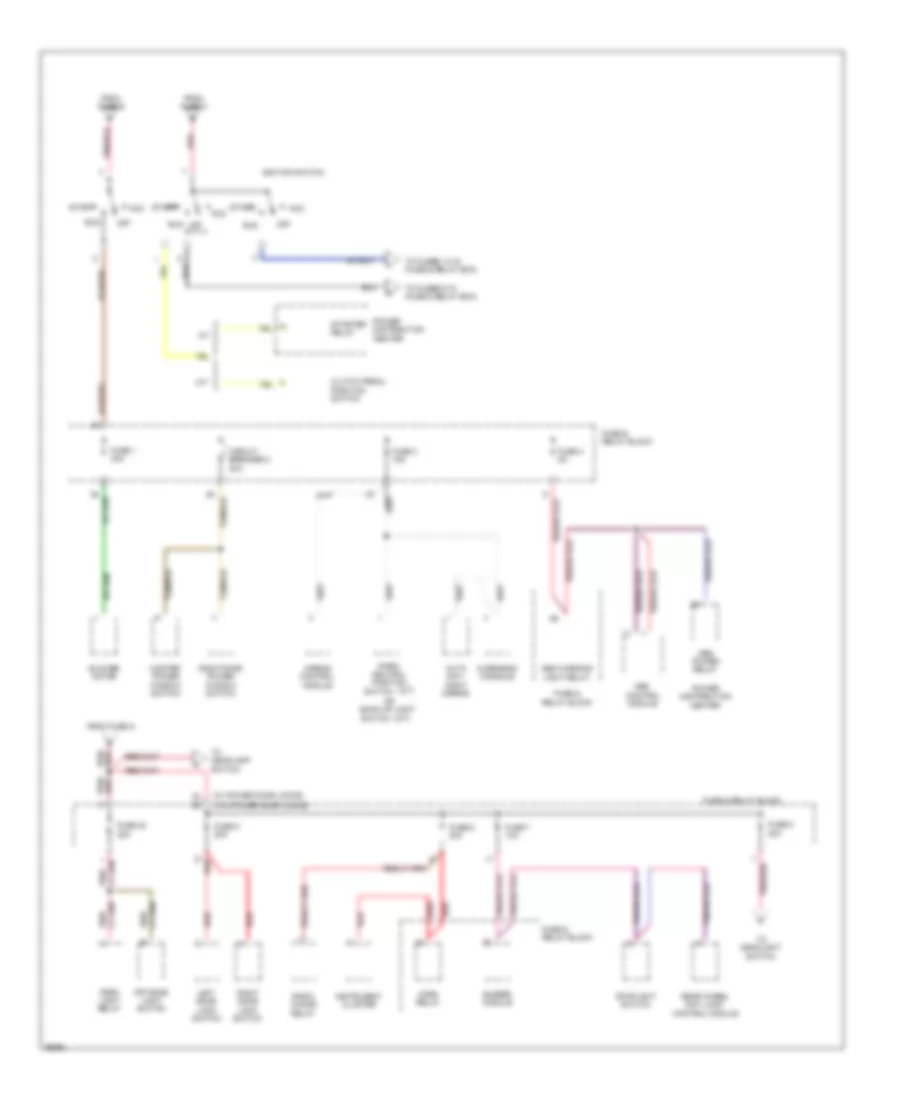
POWER DISTRIBUTION
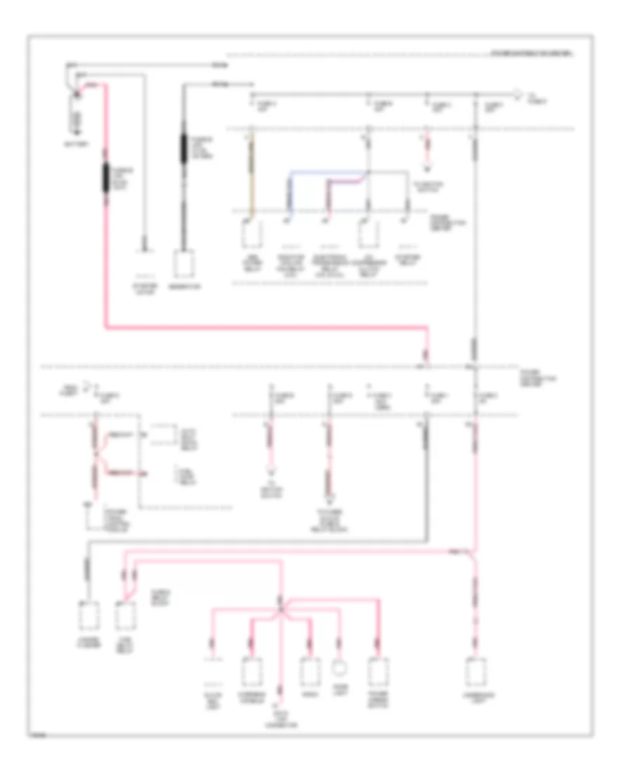
Power Distribution Wiring Diagram (1 of 4) for Dodge Dakota 1996
List of elements for Power Distribution Wiring Diagram (1 of 4) for Dodge Dakota 1996:
- (not used)
- A/c compressor clutch relay
- A22
- Abs power relay
- Auto shut down relay
- Battery
- C red
- Data link connector
- Dome light
- Electronic transmission relay (3.9l & 5.2l)
- From fuse f
- Fuel pump relay
- Fuse & relay block
- Fuse 1 20a
- Fuse 2 5a
- Fuse a 40a
- Fuse b 30a
- Fuse c 40a
- Fuse d 30a
- Fuse e 50a
- Fuse f 20a
- Fuse g 50a
- Fuse h
- Generator
- Glove box light
- Hazard flasher
- Overhead console
- Pnk
- Pnk a1
- Power distribution center
- Power distribution center
- Power mirror switch
- Power- train control module
- Radiator cooling fan relay (2.5l)
- Radio
- Starter motor
- Starter relay
- Time delay relay
- To fuse d
- To fuses 5-8 & 20 (fuse & relay block)
- To ignition switch
- Underhood light
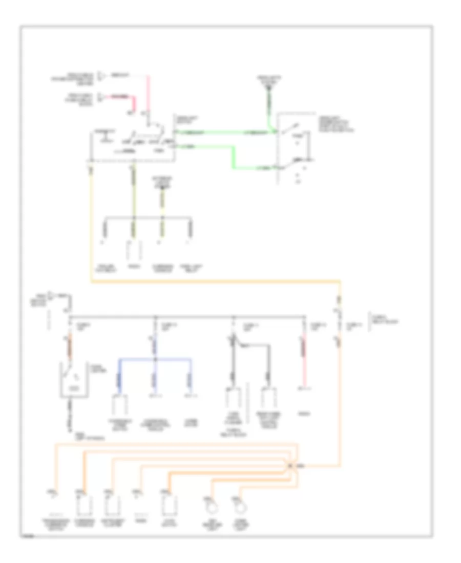
Power Distribution Wiring Diagram (2 of 4) for Dodge Dakota 1996
List of elements for Power Distribution Wiring Diagram (2 of 4) for Dodge Dakota 1996:
- (a/t)
- (m/t)
- (w/ power door locks)
- (w/o power door locks)
- A/t
- Abs control module
- Abs power relay
- Abs warning light relay
- Acc
- Airbag control module
- Auto day/ night mirror
- Blower motor
- Buzzer module
- Circuit breaker 2 30a
- Clutch pedal position switch
- From fuse c
- From fuse e
- From fuse g
- Fuse & relay block
- Fuse 1 30a
- Fuse 20 25a
- Fuse 3 15a
- Fuse 4 5a
- Fuse 5 20a
- Fuse 6 20a
- Fuse 7 10a
- Fuse 8 20a
- Horn relay
- Ignition switch
- Instrument cluster
- Left door lock switch
- M/t
- Master power window switch
- Off
- Off road light switch
- Or back-up light
- Overhead console
- Park light relay
- Park/ neutral position
- Pnk/
- Pnk/red
- Power distribution center
- Radio choke relay
- Rear wheel anti lock control module
- Red
- Right door lock switch
- Right door power window switch
- Run
- Start
- Starter relay
- Stoplight switch
- Switch
- To fuses 14-16 (fuse & relay box)
- To fuses 9-12 (fuse & relay box)
- To headlamp switch
- To headlight switch
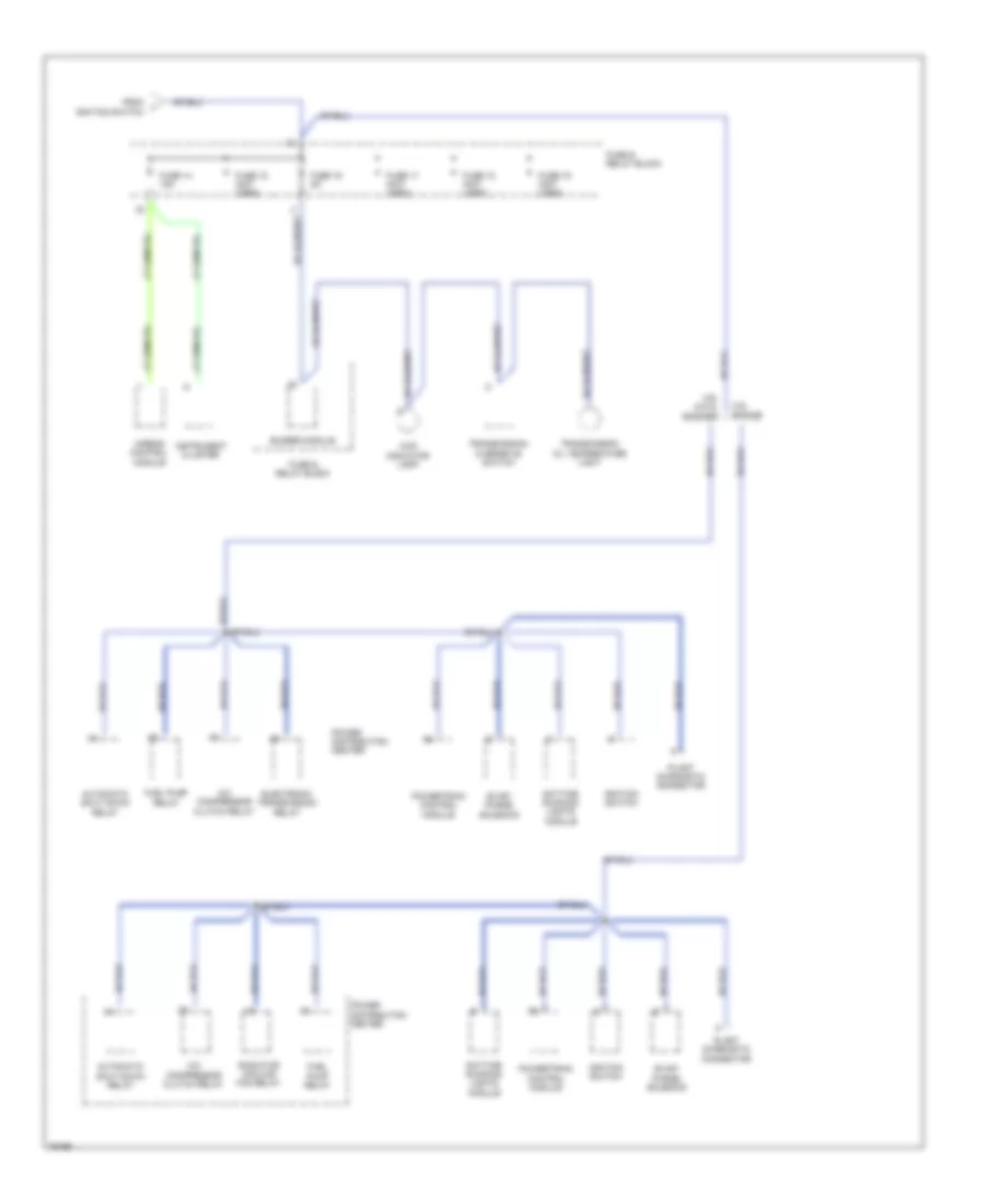
Power Distribution Wiring Diagram (3 of 4) for Dodge Dakota 1996
List of elements for Power Distribution Wiring Diagram (3 of 4) for Dodge Dakota 1996:
- (fuse & relay block)
- Ash receiver light
- Cigar lighter
- Cigar lighter light
- Exterior lights system
- From fuse 20 (power distribution center)
- From fuse 8
- From h ignition switch
- Fuse & relay block
- Fuse 10 20a
- Fuse 11 20a
- Fuse 12 10a
- Fuse 13 4a
- Fuse 9 15a
- G206 (left of radio)
- Head
- Headlight dimmer switch (part of multi- function switch)
- Headlight switch
- Headlights system (drl)
- High
- Hvac switch
- Instrument cluster
- Off
- Overhead console
- Park
- Park light relay
- Pass
- Pnk/red
- Radio
- Rear wheel anti-lock control module
- Red/tan
- Rheostat
- Tan
- Trailer tow relay
- Transmission overdrive switch
- Turn signal flasher
- Windshield wiper control module
- Windshield wiper switch
- Wiper motor
Power Distribution Wiring Diagram (4 of 4) for Dodge Dakota 1996
List of elements for Power Distribution Wiring Diagram (4 of 4) for Dodge Dakota 1996:
- 2.5l engine
- 3.9l & 5.2l engines
- 4wd indicator lamp
- A/c compressor clutch relay
- Airbag control module
- Automatic shut down relay
- Buzzer module
- Daytime running lights module
- Electronic transmission relay
- Evap/ purge solenoid
- From ignition switch
- Fuel pump relay
- Fuse & relay block
- Fuse 14 15a
- Fuse 15 (not used)
- Fuse 16 5a
- Fuse 17 (not used)
- Fuse 18 (not used)
- Fuse 19 (not used)
- Ignition switch
- Instrument cluster
- Plant diagnostic connector
- Power distribution center
- Powertrain control module
- Radiator cooling fan relay
- Transmission oil temperature light
- Transmission overdrive switch
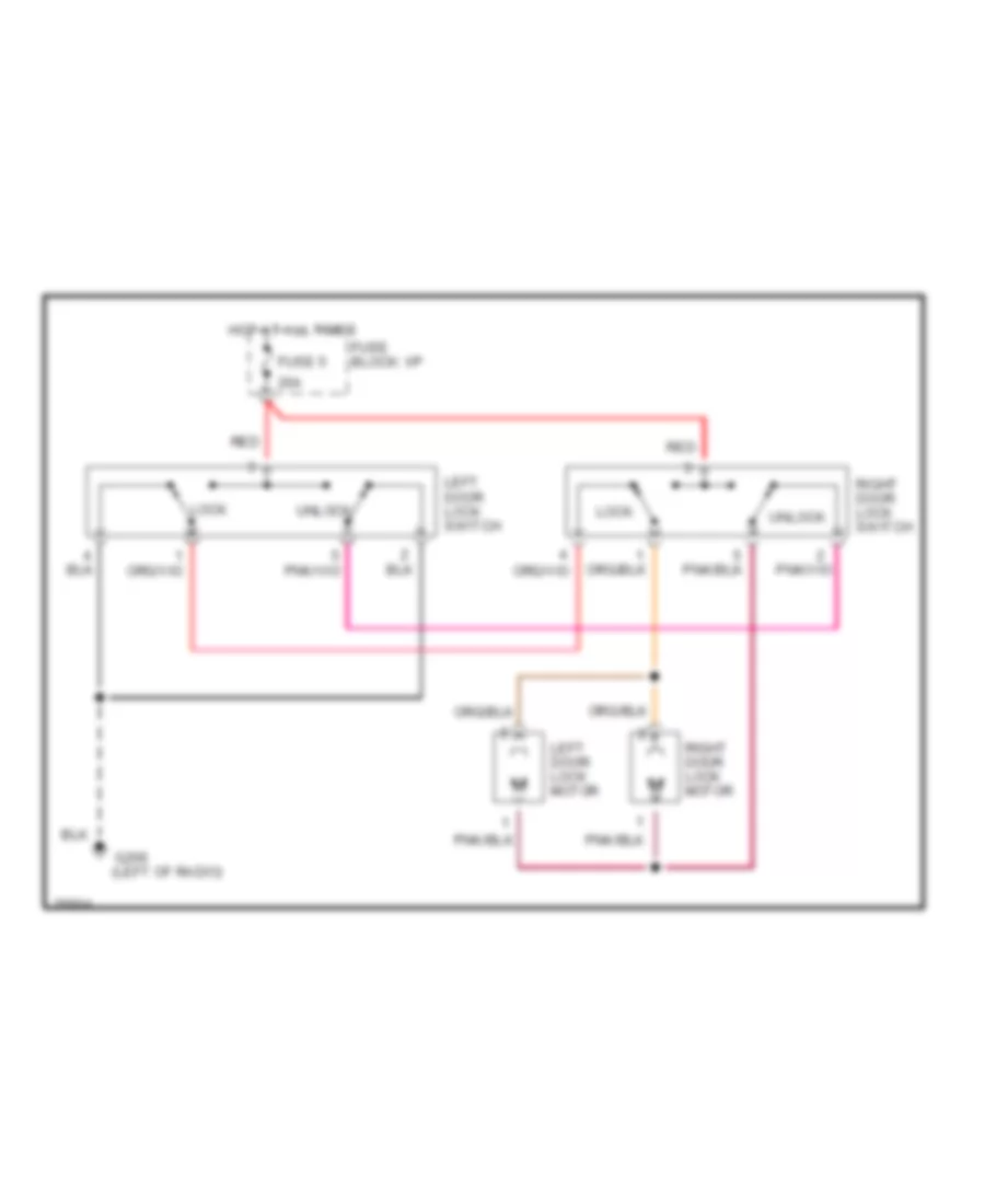
POWER DOOR LOCKS
Power Door Lock Wiring Diagram for Dodge Dakota 1996
List of elements for Power Door Lock Wiring Diagram for Dodge Dakota 1996:
- (left of radio)
- 20a
- Fuse 5
- Fuse block: i/p
- G206
- Hot at all times
- Left door lock motor
- Left door lock switch
- Lock
- Red
- Right door lock motor
- Right door lock switch
- Unlock
POWER MIRRORS
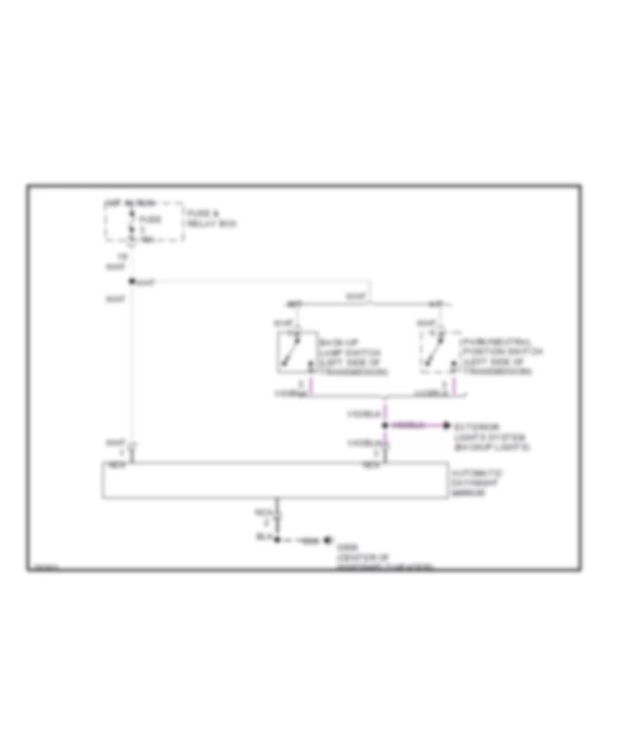
Automatic Day/Night Mirror Wiring Diagram for Dodge Dakota 1996
List of elements for Automatic Day/Night Mirror Wiring Diagram for Dodge Dakota 1996:
- A/t
- Automatic day/night mirror
- Back-up lamp switch (left side of transmission)
- Exterior lights system (backup lights)
- Fuse & relay box
- Fuse 15a
- G908 (center of windshield header)
- Hot in run
- M/t
- Nca
- Park/neutral position switch (left side of transmission)
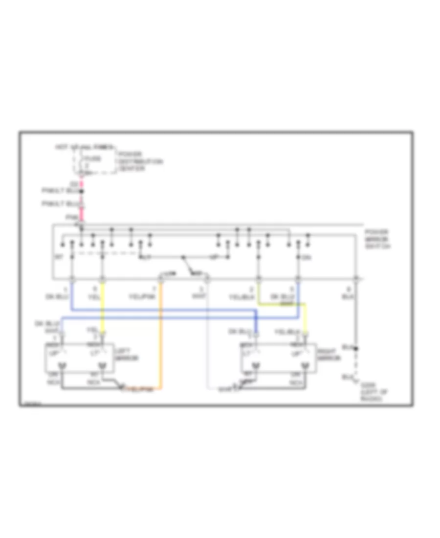
Power Mirror Wiring Diagram for Dodge Dakota 1996
List of elements for Power Mirror Wiring Diagram for Dodge Dakota 1996:
- Fuse 5a
- G206 (left of radio)
- Hot at all times
- Left mirror
- Nca
- Pnk
- Power distribution center
- Power mirror switch
- Right mirror
POWER WINDOWS
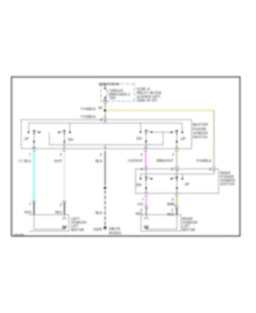
Power Window Wiring Diagram for Dodge Dakota 1996
List of elements for Power Window Wiring Diagram for Dodge Dakota 1996:
- (near radio)
- Circuit breaker 2 30a
- Fuse & relay block (lower left side of i/p)
- G206
- Hot in run
- Left window lift motor
- Master power window switch
- Nca
- Right power window switch
- Right window lift motor
RADIO
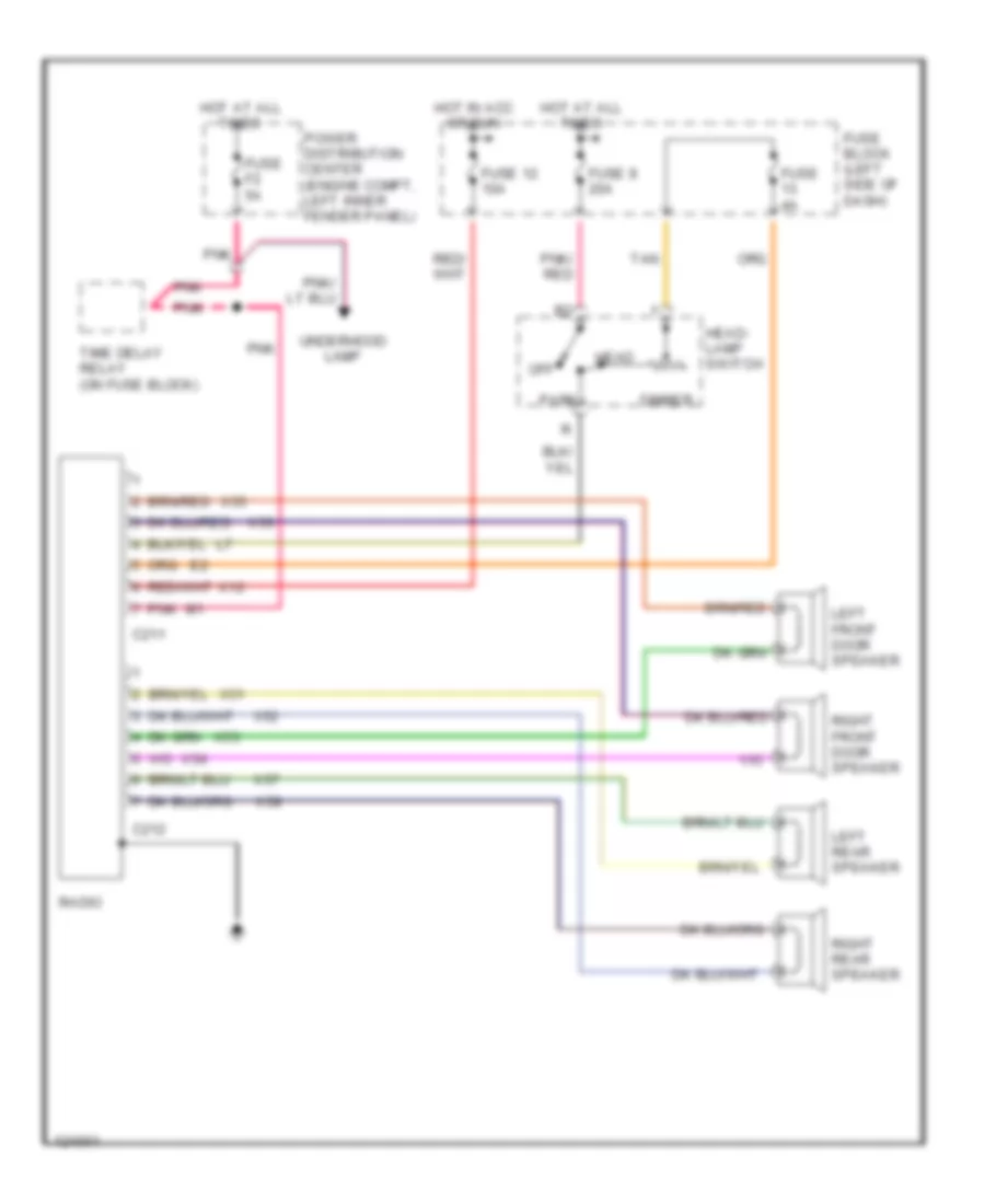
Radio Wiring Diagrams, Base for Dodge Dakota 1996
List of elements for Radio Wiring Diagrams, Base for Dodge Dakota 1996:
- C211
- C212
- Dimmer
- Fuse 12 10a
- Fuse 4a
- Fuse 8 20a
- Fuse block (left side of dash)
- Fuse f2 5a
- Head
- Head- lamp switch
- Hot at all times
- Hot in acc or run
- Left front door speaker
- Left rear speaker
- Off
- Park
- Pnk
- Pnk/ red
- Power distribution center (engine compt, left inner fender panel)
- Radio
- Right front door speaker
- Right rear speaker
- Tan
- Time delay relay (on fuse block)
- Underhood lamp
- X12
- X51
- X52
- X53
- X54
- X55
- X56
- X57
- X58
Radio Wiring Diagrams, Premium Model for Dodge Dakota 1996
List of elements for Radio Wiring Diagrams, Premium Model for Dodge Dakota 1996:
- C211
- C212
- Dimmer
- Fuse 12 10a
- Fuse 13 4a
- Fuse 20a
- Fuse 8 20a
- Fuse block (left side of dash)
- Fuse f2 5a
- G206 (center of dash)
- Head
- Headlamp switch
- Hot at all times
- Hot in acc or run
- Left front door speaker
- Left rear speaker
- Off
- Park
- Pnk
- Pnk/ red
- Power distribution center (engine compt, left inner fender panel)
- Radio
- Radio choke relay
- Right front door speaker
- Right rear speaker
- Tan
- Time delay relay (on fuse block)
- Underhood lamp
- X12
- X15
- X51
- X52
- X53
- X54
- X55
- X56
- X57
- X58
- X60
STARTING/CHARGING
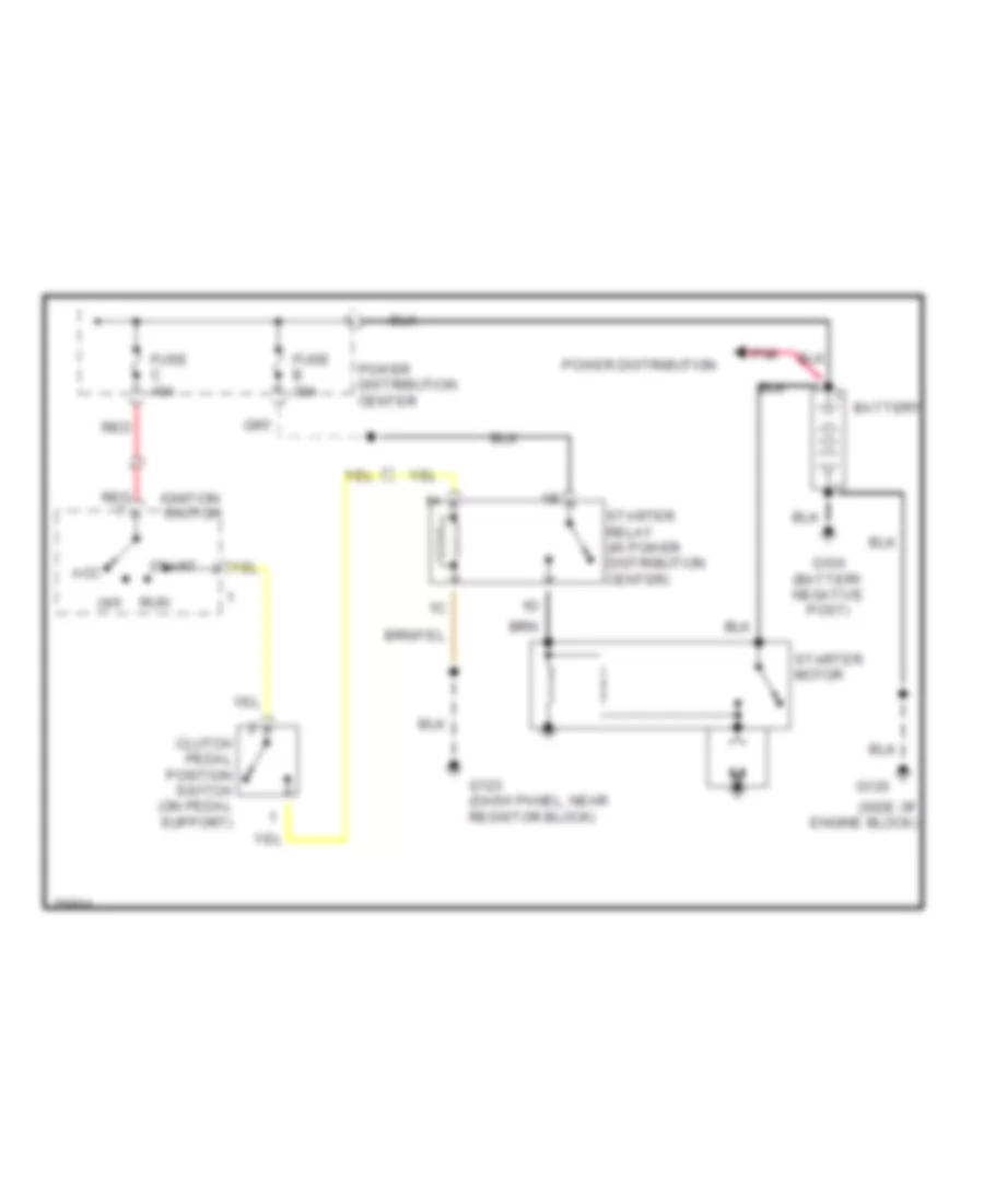
2.5L
2.5L, Starting Wiring Diagram for Dodge Dakota 1996
List of elements for 2.5L, Starting Wiring Diagram for Dodge Dakota 1996:
- (side of engine block)
- Acc
- Battery
- Clutch pedal position switch (on pedal support)
- Fuse b 30a
- Fuse c 40a
- G120
- G123 (dash panel, near resistor block)
- Ignition switch
- Off
- Pnk
- Power distribution
- Power distribution center
- Red
- Run
- Start
- Starter motor
- Starter relay (in power distribution center)
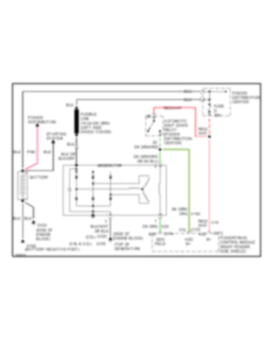
Charging Wiring Diagram for Dodge Dakota 1996
List of elements for Charging Wiring Diagram for Dodge Dakota 1996:
- (2.5l)
- (3.9l & 5.2l)
- (side of engine block)
- (top of generator)
- A22
- Asd b+
- Automatic shut down relay (power distribution center)
- B10
- Battery
- C12
- C173
- C174
- C175
- Fuse d 30a
- G120
- G125
- Gen field
- Generator
- Pnk
- Power distribution
- Power distribution center
- Powertrain control module (right fender side shield)
- Starting system
3.9L
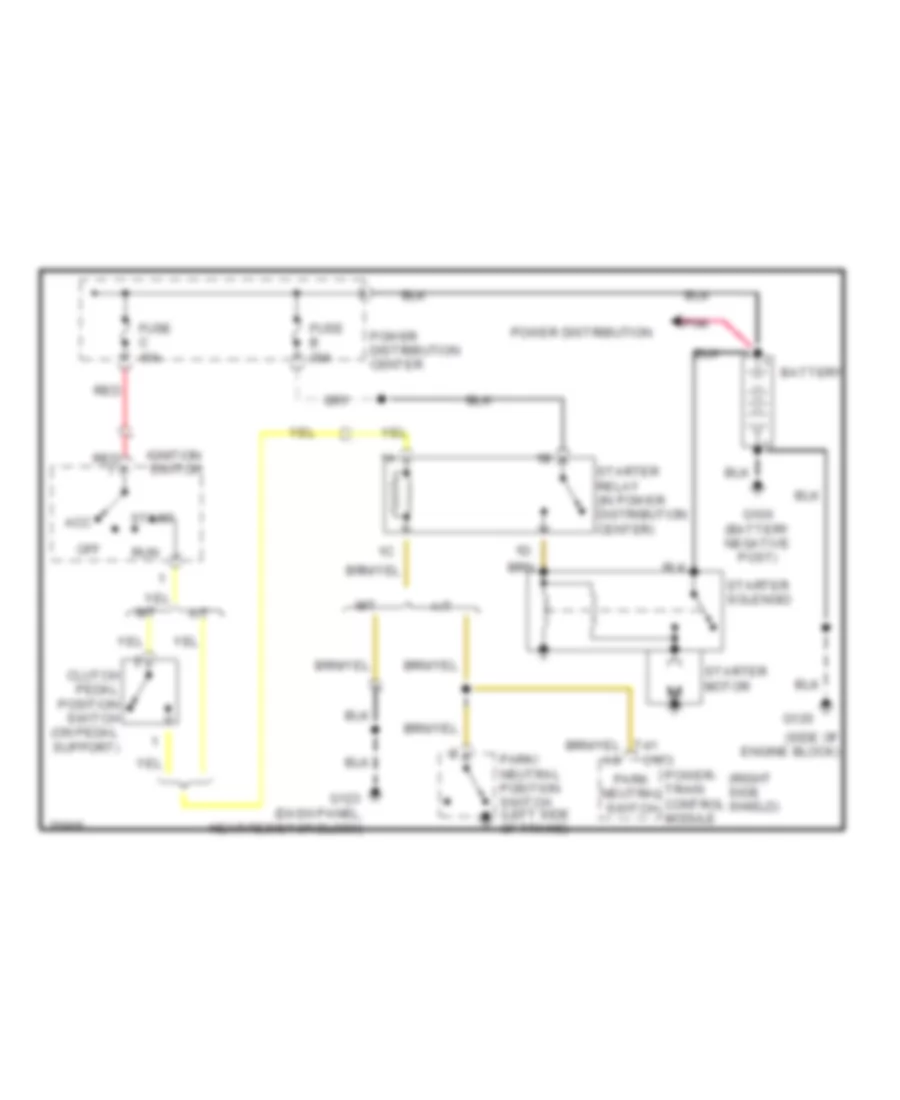
3.9L, Starting Wiring Diagram for Dodge Dakota 1996
List of elements for 3.9L, Starting Wiring Diagram for Dodge Dakota 1996:
- (dash panel, near resistor block)
- (right side shield)
- (side of engine block)
- A/t
- Acc
- Battery
- C173
- Clutch pedal position switch (on pedal support)
- Fuse b 30a
- Fuse c 40a
- G120
- G123
- Ignition switch
- M/t
- Off
- Park neutral switch
- Park/ neutral position switch (left side of trans)
- Pnk
- Power distribution
- Power distribution center
- Power- train control module
- Red
- Run
- Start
- Starter motor
- Starter relay (in power distribution center)
- Starter solenoid
- T41
Charging Wiring Diagram for Dodge Dakota 1996
List of elements for Charging Wiring Diagram for Dodge Dakota 1996:
- (2.5l)
- (3.9l & 5.2l)
- (side of engine block)
- (top of generator)
- A22
- Asd b+
- Automatic shut down relay (power distribution center)
- B10
- Battery
- C12
- C173
- C174
- C175
- Fuse d 30a
- G120
- G125
- Gen field
- Generator
- Pnk
- Power distribution
- Power distribution center
- Powertrain control module (right fender side shield)
- Starting system
5.2L
5.2L, Starting Wiring Diagram for Dodge Dakota 1996
List of elements for 5.2L, Starting Wiring Diagram for Dodge Dakota 1996:
- (dash panel, near resistor block)
- (right side shield)
- (side of engine block)
- A/t
- Acc
- Battery
- C173
- Clutch pedal position switch (on pedal support)
- Fuse b 30a
- Fuse c 40a
- G120
- G123
- Ignition switch
- M/t
- Off
- Park neutral switch
- Park/ neutral position switch (left side of trans)
- Pnk
- Power distribution
- Power distribution center
- Power- train control module
- Red
- Run
- Start
- Starter motor
- Starter relay (in power distribution center)
- Starter solenoid
- T41
Charging Wiring Diagram for Dodge Dakota 1996
List of elements for Charging Wiring Diagram for Dodge Dakota 1996:
- (2.5l)
- (3.9l & 5.2l)
- (side of engine block)
- (top of generator)
- A22
- Asd b+
- Automatic shut down relay (power distribution center)
- B10
- Battery
- C12
- C173
- C174
- C175
- Fuse d 30a
- G120
- G125
- Gen field
- Generator
- Pnk
- Power distribution
- Power distribution center
- Powertrain control module (right fender side shield)
- Starting system
SUPPLEMENTAL RESTRAINTS
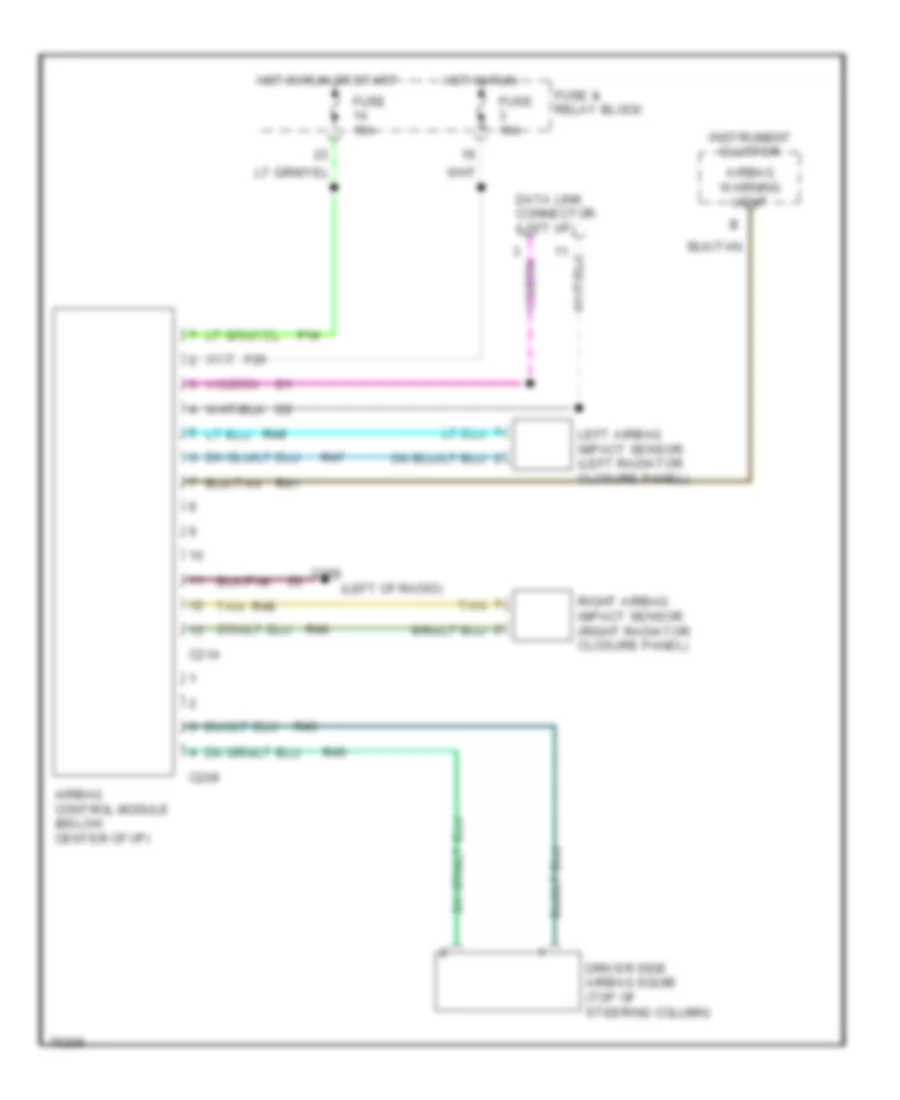
Supplemental Restraint Wiring Diagram for Dodge Dakota 1996
List of elements for Supplemental Restraint Wiring Diagram for Dodge Dakota 1996:
- (left of radio)
- Airbag control module (below center of i/p)
- Airbag warning light
- C209
- C214
- Cluster
- Data link connector (left i/p)
- Driver side airbag squib (top of steering column)
- F14
- F20
- Fuse & relay block
- Fuse 15a
- G206
- Hot in run
- Hot in run or start
- Instrument
- Left airbag impact sensor (left radiator closure panel)
- R41
- R43
- R45
- R46
- R47
- R48
- R49
- Right airbag impact sensor (right radiator closure panel)
- Tan
TRANSMISSION
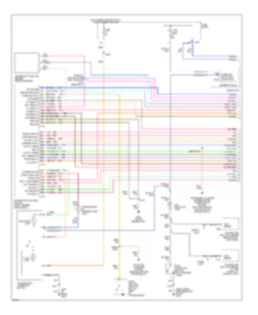
3.9L
3.9L, Transmission Wiring Diagram (1 of 2) for Dodge Dakota 1996
List of elements for 3.9L, Transmission Wiring Diagram (1 of 2) for Dodge Dakota 1996:
- (dash panel, near resistor block) g123
- (left of radio) g206
- (near pcm)
- (partial splice; after fuel injector no.1 breakout)
- 4wd indicator lamp
- 4wd indicator switch (on transfer case)
- 4wd sense
- A14
- A15
- A16
- A17
- A21
- A22
- A23
- A27
- A31
- A32
- B11
- B21
- B25
- B27
- B28
- B29
- B30
- B31
- Batt temp sens
- Buzzer module
- C118
- C13
- C15
- C173
- C174
- C175
- C202
- C234
- C27
- C28
- C29
- C30
- Ccd bus +
- Ccd bus -
- Ckp sens
- Controller anti-lock brake (at abs hydraulic control unit)
- Controller anti-lock brake (behind right kick panel
- Crankshaft position sensor (rear of engine)
- D20
- D21
- Ect sens in
- Fuse 4a
- Fuse 5a
- Fuse block
- Fused b (+)
- Fused ign sw output (run/start) c234
- G107
- G125 (top of generator)
- G14
- Gov press sig
- Ground
- Hot w/headlamp switch in park or head position
- Iat sens in
- Ign power
- Illum. lamp
- Indicator lamp
- Instrument cluster (speedometer) & headlights system (daytime running lights module) (canada only)
- K118
- K21
- K22
- K24
- K54
- Map sens in
- Output sens
- Overdrive ind
- Overdrive sol
- Park/ neutral position switch (side of transmission)
- Park/neutral
- Pnk
- Powertrain control module (right fender side shield)
- S121
- S129
- S203
- S217
- Sci receive
- Sci transmit
- Sensor ground
- Starting/ charging system (engine starter motor relay)
- T13
- T14
- T18
- T25
- T30
- T33
- T41
- T54
- T59
- T60
- Tcc sol ctrl
- Tps sens in
- Trans od
- Trans relay
- Trans temp in
- Trans temp ind
- Transmission oil temperature lamp
- Transmission overdrive switch
- Var force sol
- Vss in
- W/abs only
- W/rwal only
- Z12
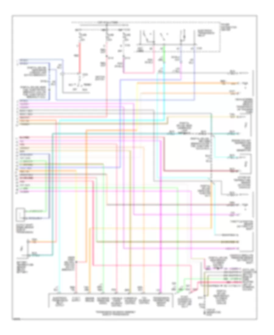
3.9L, Transmission Wiring Diagram (2 of 2) for Dodge Dakota 1996
List of elements for 3.9L, Transmission Wiring Diagram (2 of 2) for Dodge Dakota 1996:
- (bottom edge of knee bolster,
- (near park/ neutral position switch breakout)
- (not used)
- (partial splice;
- (partial splice; (near fuel injector no.7)
- (partial splice; near brake warning lamp switch breakout)
- (partial splice; near branch to airbag control module)
- (partial splice; near branch to airbag control module)
- (partial splice; near fuel injector no.6 breakout) (3.9l) or fuel injector no.8 breakout) (5.2l)
- (partial splice; near underhood lamp breakout
- (top of generator) g125
- Acc
- Battery temperature sensor (below battery)
- Between
- Breakouts for fuel injectors no.2 & no.4)
- C120
- C232
- D20
- D21
- Electronic transmission relay
- Electronic transmission relay output
- Engine coolant temperature sensor (near generator)
- Fuse b 30a
- Fuse c 40a
- Fuse d 30a
- Governor pressure signal
- Hot at all times
- Ignition switch
- Intake air temperature sensor (on intake manifold)
- Left of steering column)
- Manifold absolute pressure sensor (on throttle body)
- Off
- Output shaft speed sensor (side of transmission)
- Overdrive solenoid control
- Plant diagnostic connector (plant use only)
- Pnk
- Power distribution center
- Red
- Run
- S115
- S118
- S121
- Sensor ground
- Start
- Tcc solenoid control
- Throttle position sensor (on throttle body)
- Transmission solenoid assembly (side of transmission)
- Transmission temperature sensor signal
- Variable force solenoid control
- Vehicle speed sensor (rear of transmission or transfer case)
- Z12
5.2L
5.2L, Transmission Wiring Diagram (1 of 2) for Dodge Dakota 1996
List of elements for 5.2L, Transmission Wiring Diagram (1 of 2) for Dodge Dakota 1996:
- (dash panel, near resistor block) g123
- (left of radio) g206
- (near pcm)
- (partial splice; after fuel injector no.1 breakout)
- 4wd indicator lamp
- 4wd indicator switch (on transfer case)
- 4wd sense
- A14
- A15
- A16
- A17
- A21
- A22
- A23
- A27
- A31
- A32
- B11
- B21
- B25
- B27
- B28
- B29
- B30
- B31
- Batt temp sens
- Buzzer module
- C118
- C13
- C15
- C173
- C174
- C175
- C202
- C234
- C27
- C28
- C29
- C30
- Ccd bus +
- Ccd bus -
- Ckp sens
- Controller anti-lock brake (at abs hydraulic control unit)
- Controller anti-lock brake (behind right kick panel
- Crankshaft position sensor (rear of engine)
- D20
- D21
- Ect sens in
- Fuse 4a
- Fuse 5a
- Fuse block
- Fused b (+)
- Fused ign sw output (run/start) c234
- G107
- G125 (top of generator)
- G14
- Gov press sig
- Ground
- Hot w/headlamp switch in park or head position
- Iat sens in
- Ign power
- Illum. lamp
- Indicator lamp
- Instrument cluster (speedometer) & headlights system (daytime running lights module) (canada only)
- K118
- K21
- K22
- K24
- K54
- Map sens in
- Output sens
- Overdrive ind
- Overdrive sol
- Park/ neutral position switch (side of transmission)
- Park/neutral
- Pnk
- Powertrain control module (right fender side shield)
- S121
- S129
- S203
- S217
- Sci receive
- Sci transmit
- Sensor ground
- Starting/ charging system (engine starter motor relay)
- T13
- T14
- T18
- T25
- T30
- T33
- T41
- T54
- T59
- T60
- Tcc sol ctrl
- Tps sens in
- Trans od
- Trans relay
- Trans temp in
- Trans temp ind
- Transmission oil temperature lamp
- Transmission overdrive switch
- Var force sol
- Vss in
- W/abs only
- W/rwal only
- Z12
5.2L, Transmission Wiring Diagram (2 of 2) for Dodge Dakota 1996
List of elements for 5.2L, Transmission Wiring Diagram (2 of 2) for Dodge Dakota 1996:
- (bottom edge of knee bolster,
- (near park/ neutral position switch breakout)
- (not used)
- (partial splice;
- (partial splice; (near fuel injector no.7)
- (partial splice; near brake warning lamp switch breakout)
- (partial splice; near branch to airbag control module)
- (partial splice; near branch to airbag control module)
- (partial splice; near fuel injector no.6 breakout) (3.9l) or fuel injector no.8 breakout) (5.2l)
- (partial splice; near underhood lamp breakout
- (top of generator) g125
- Acc
- Battery temperature sensor (below battery)
- Between
- Breakouts for fuel injectors no.2 & no.4)
- C120
- C232
- D20
- D21
- Electronic transmission relay
- Electronic transmission relay output
- Engine coolant temperature sensor (near generator)
- Fuse b 30a
- Fuse c 40a
- Fuse d 30a
- Governor pressure signal
- Hot at all times
- Ignition switch
- Intake air temperature sensor (on intake manifold)
- Left of steering column)
- Manifold absolute pressure sensor (on throttle body)
- Off
- Output shaft speed sensor (side of transmission)
- Overdrive solenoid control
- Plant diagnostic connector (plant use only)
- Pnk
- Power distribution center
- Red
- Run
- S115
- S118
- S121
- Sensor ground
- Start
- Tcc solenoid control
- Throttle position sensor (on throttle body)
- Transmission solenoid assembly (side of transmission)
- Transmission temperature sensor signal
- Variable force solenoid control
- Vehicle speed sensor (rear of transmission or transfer case)
- Z12
WARNING SYSTEMS
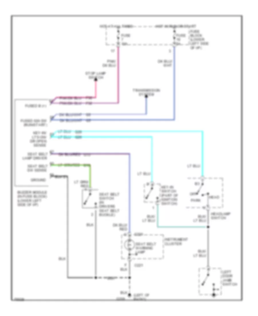
Warning System Wiring Diagrams for Dodge Dakota 1996
List of elements for Warning System Wiring Diagrams for Dodge Dakota 1996:
- (left of radio)
- Buzzer module (in fuse block) (lower left side of i/p)
- C221
- F32
- Fuse 10a
- Fuse 5a
- Fuse block (lower left side of i/p)
- Fused b (+)
- Fused ign sw (run/start)
- G206
- Ground
- Head
- Headlamp switch
- Hot at all times
- Hot in run or start
- Instrument cluster
- Key-in switch (part of ignition switch)
- Key-in/
- Lamp driver
- Left door jamb switch
- Lts-on/ dr open sense
- Off
- Park
- Seat belt
- Seat belt switch (in drivers seat belt buckle)
- Seat belt warning lamp
- Stop lamp switch
- Sw sense
- Transmission system
WIPER/WASHER
Wiper/Washer Wiring Diagram for Dodge Dakota 1996
List of elements for Wiper/Washer Wiring Diagram for Dodge Dakota 1996:
- (center of
- (in washer fluid reservoir)
- Anti-lock brake controller (behind right kick panel)
- C220
- C221
- Dly
- Fuse & relay block (lower left of i/p)
- Fuse 15a
- Fuse 20a
- G104 (left fender side shield)
- G206 (left of radio)
- Hot in acc or run
- Hot in run or start
- Instrument cluster
- Intermittent wiper control module (behind top of glove box)
- Intermittent wiper motor
- Low washer fluid lamp
- Off
- Park switch
- Red/
- Safety wall)
- Tan
- V10
- Vi7
- W/ rwal only
- Washer switch
- Windshield washer fluid pump motor
- Windshield washer low fluid level sensor (in washer fluid reservoir)
- Windshield wiper switch

 Čeština
 Dansk
Dansk Deutsch
 Ελληνικά
 English
 English
 Español
 Suomi
Suomi Français
 Français
 עברית
עברית Hrvatski
 Magyar
 日本語
日本語 한국어
한국어 Nederlands
 Polski
 Português
 Português
 Română
 Русский
 Slovenčina
 Slovenščina
 Svenska
 Türkçe
 中文 (中国)