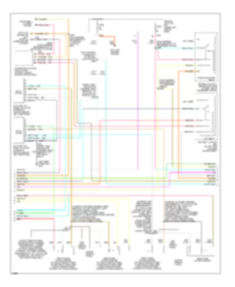
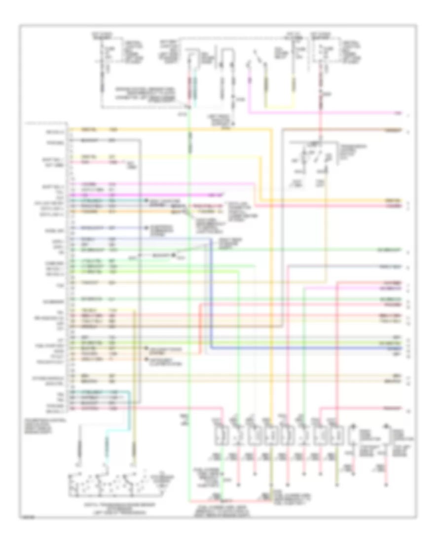
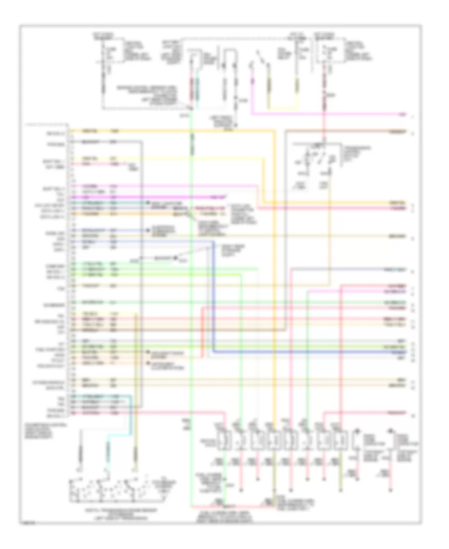
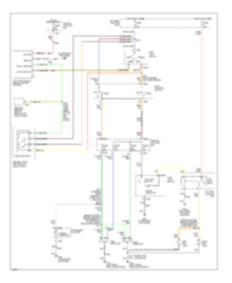
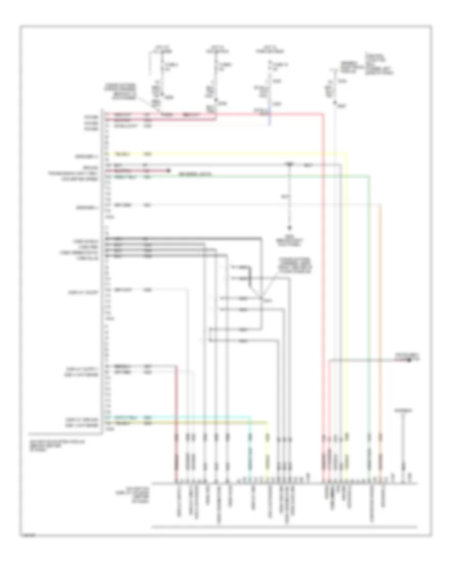
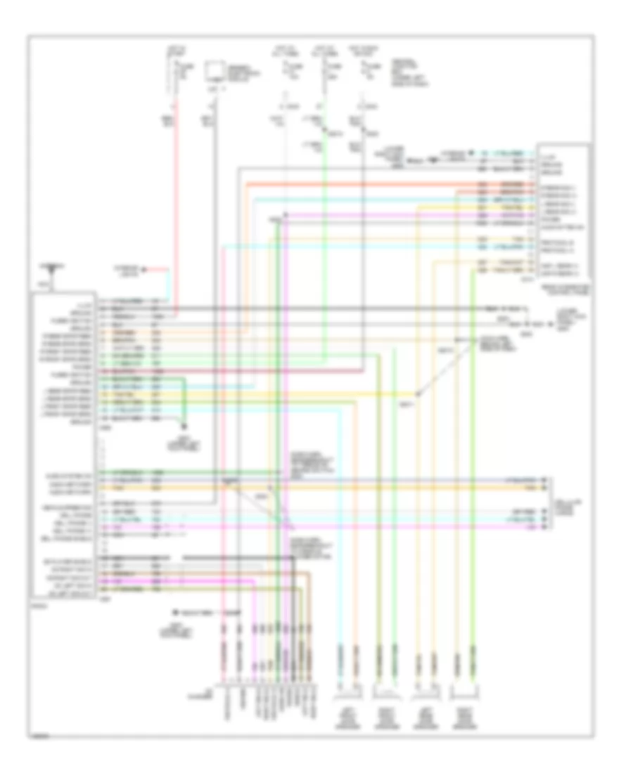
AIR CONDITIONING
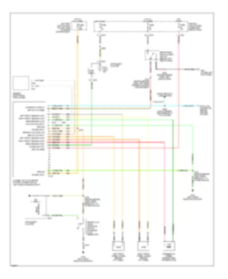
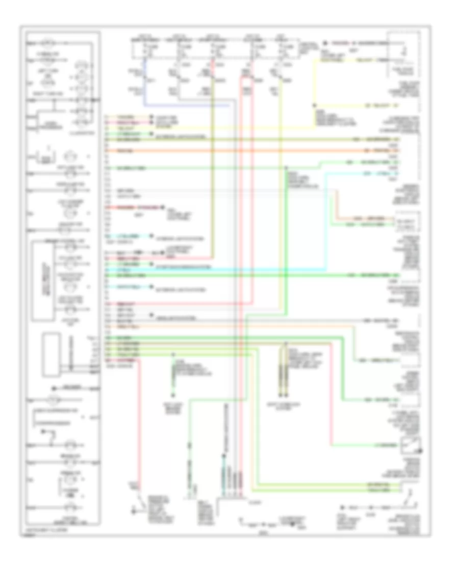
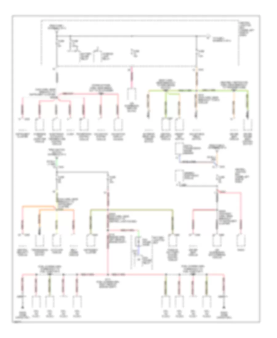
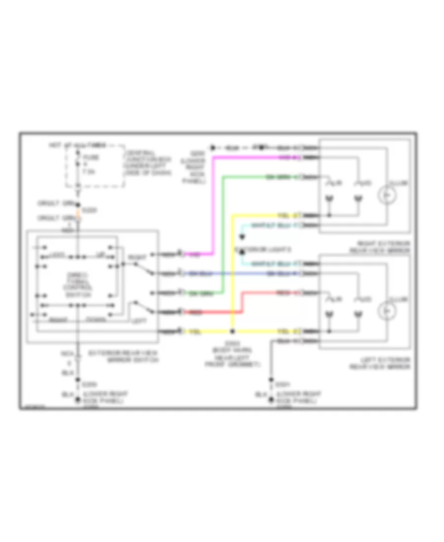
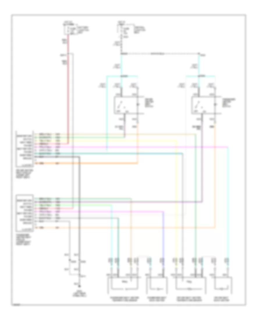
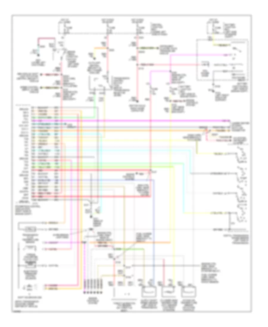
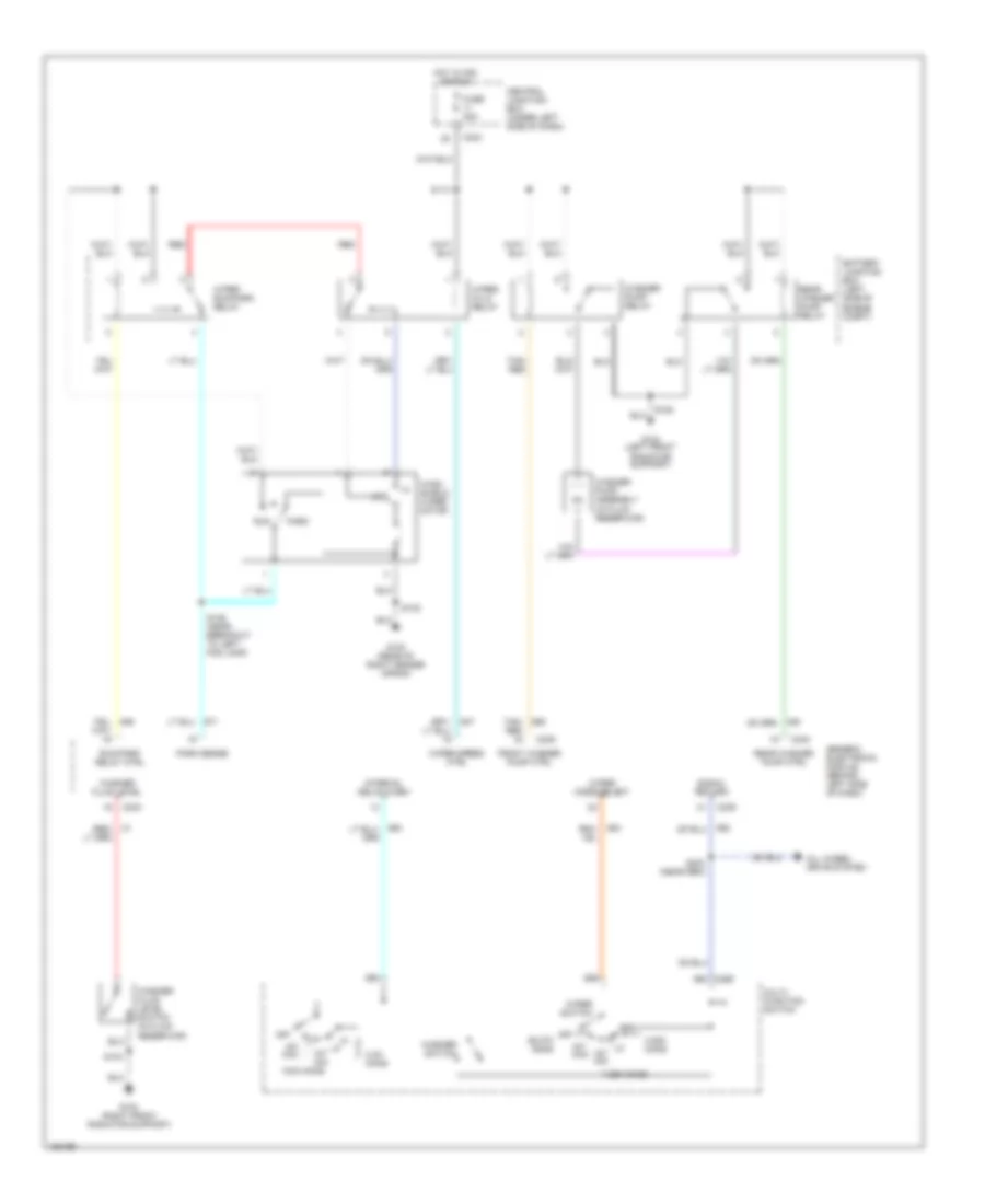
Automatic A/C Wiring Diagram (1 of 3) for Ford Expedition 2002
 https://portal-diagnostov.com/license.html
Automotive Electricians Portal FZCO
Automotive Electricians Portal FZCO
https://portal-diagnostov.com/license.html
https://portal-diagnostov.com/license.html
Automotive Electricians Portal FZCO
Automotive Electricians Portal FZCO
List of elements for Automatic A/C Wiring Diagram (1 of 3) for Ford Expedition 2002:
- (left rear wheelwell) g402
- (lower right kick panel) g200
- (main harness, near breakout to glove compartment lamp) s200
- (not used)
- (safety belt retractor harness, near breakout to rpo relay box 2) s424
- 87a
- A/c press cutoff sig
- Air bag sliding contact (at base of steering column)
- Amb temp sens input
- Ambient air temperature sensor (left front of engine compartment)
- Audio/climate control switch assembly
- Aux rly ctrl
- Auxiliary a/c control module (in rear of vehicle, behind left side panel)
- Battery
- Battery junction box (on left side of engine compartment)
- Blend door (wiper)
- Blend door 5v+
- Blend door act gnd
- Blend door actuator
- Blend door actuator (behind center of dash)
- Blower ctrl out
- Blower motor (on right side of engine compartment)
- Blower motor speed controller (behind right side of dash)
- Blower relay
- Blower/flasher relay block (behind center of dash)
- C205
- C242
- C243
- C280
- C281
- C282
- Central junction box (under left side of dash)
- Electronic automatic temperature control (eatc) module (behind center of dash)
- Front panel illum
- Fuse 10a
- Fuse 15a
- Fuse 40a
- Fuse 5a
- G200 (lower right kick panel)
- Ground
- Hot at all times
- Hot in run
- Hot in run or start
- Ignition
- In-car temp sens
- In-car temperature sensor (behind center of dash)
- Inst panel lp feed
- Interior lights system
- Nca
- Near breakout to instrument cluster)
- Red
- S134 (engine control sensor harness, near breakout to 40 pin in-line connector, left rear corner of engine compartment)
- S203 (main harness, near breakout to rpo relay block)
- S292 (main harness, near breakout to electronic automatic temperature control (eatc))
- S293 (main harness, near breakout to electronic automatic temperature control (eatc))
- Sensor input gnd
- Solid state
- Spc (+)
- Spc (-)
- Steering column assembly
- Steering whl sw
- Sunload sens input
- Sunload sensor (top right side of dash)
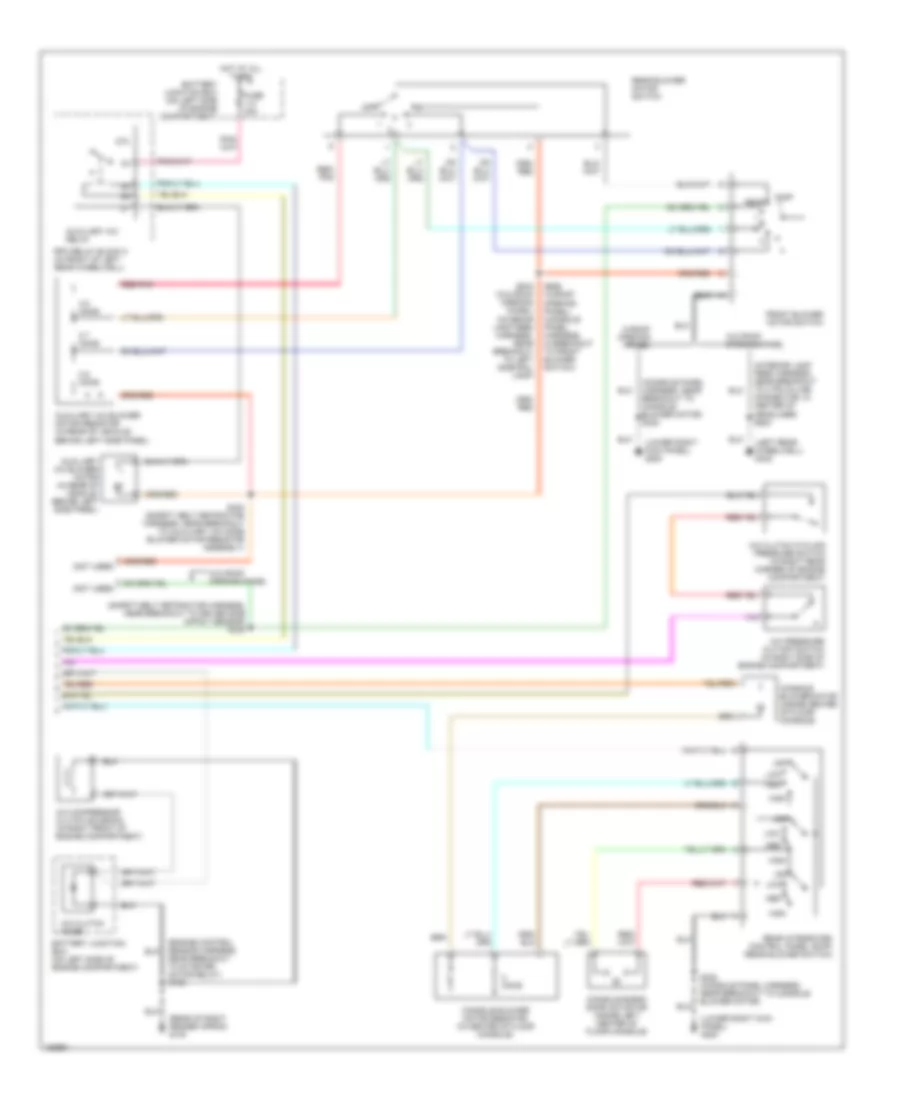
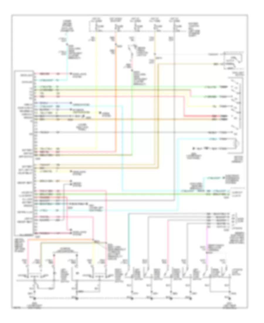
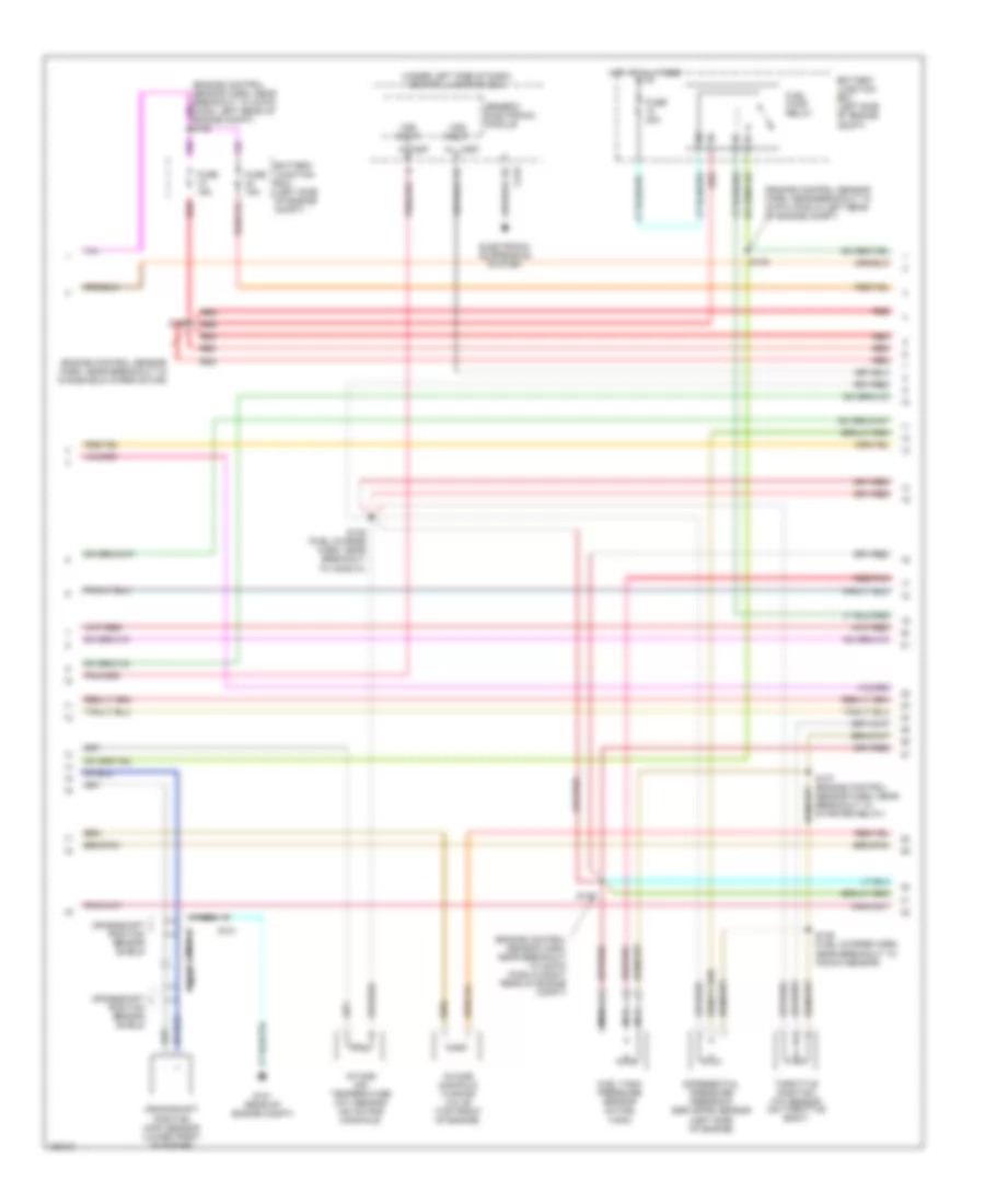
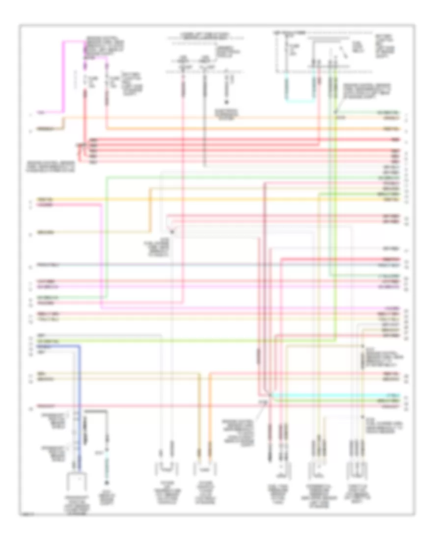
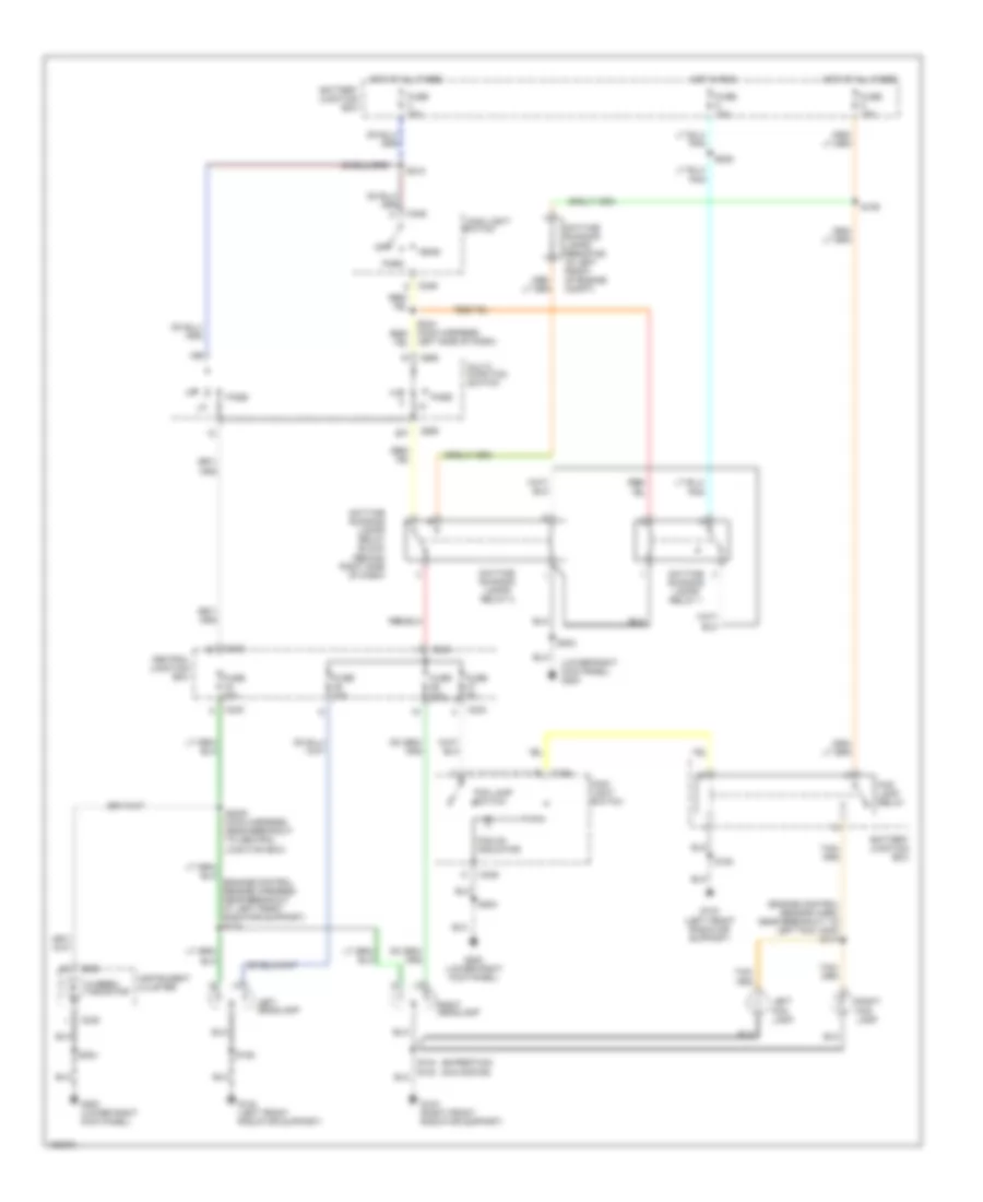
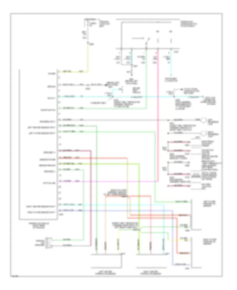
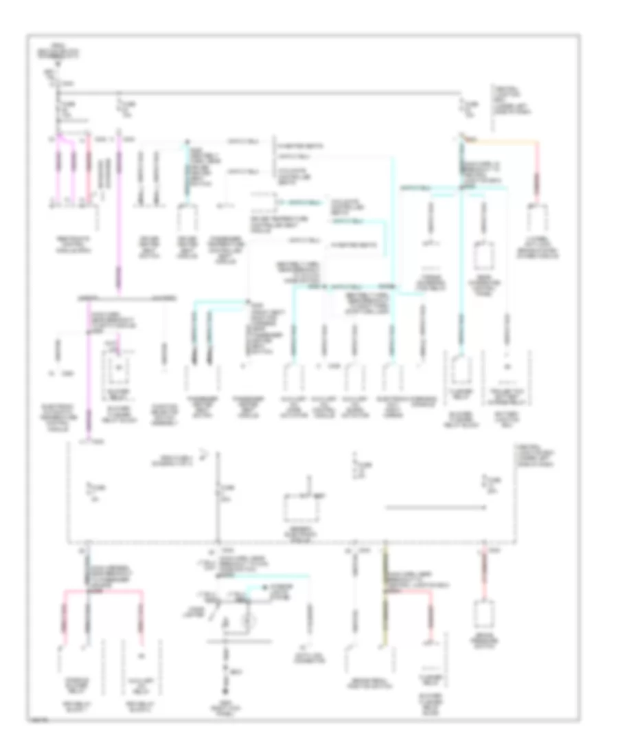
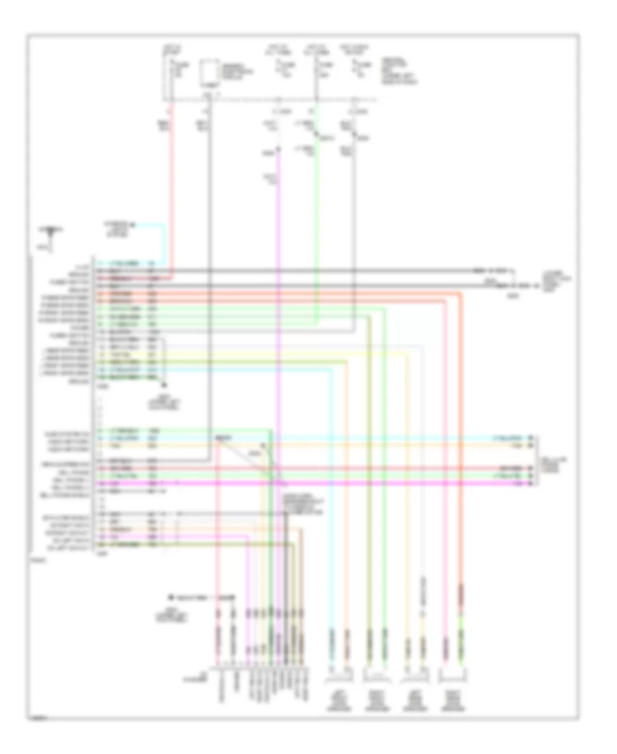
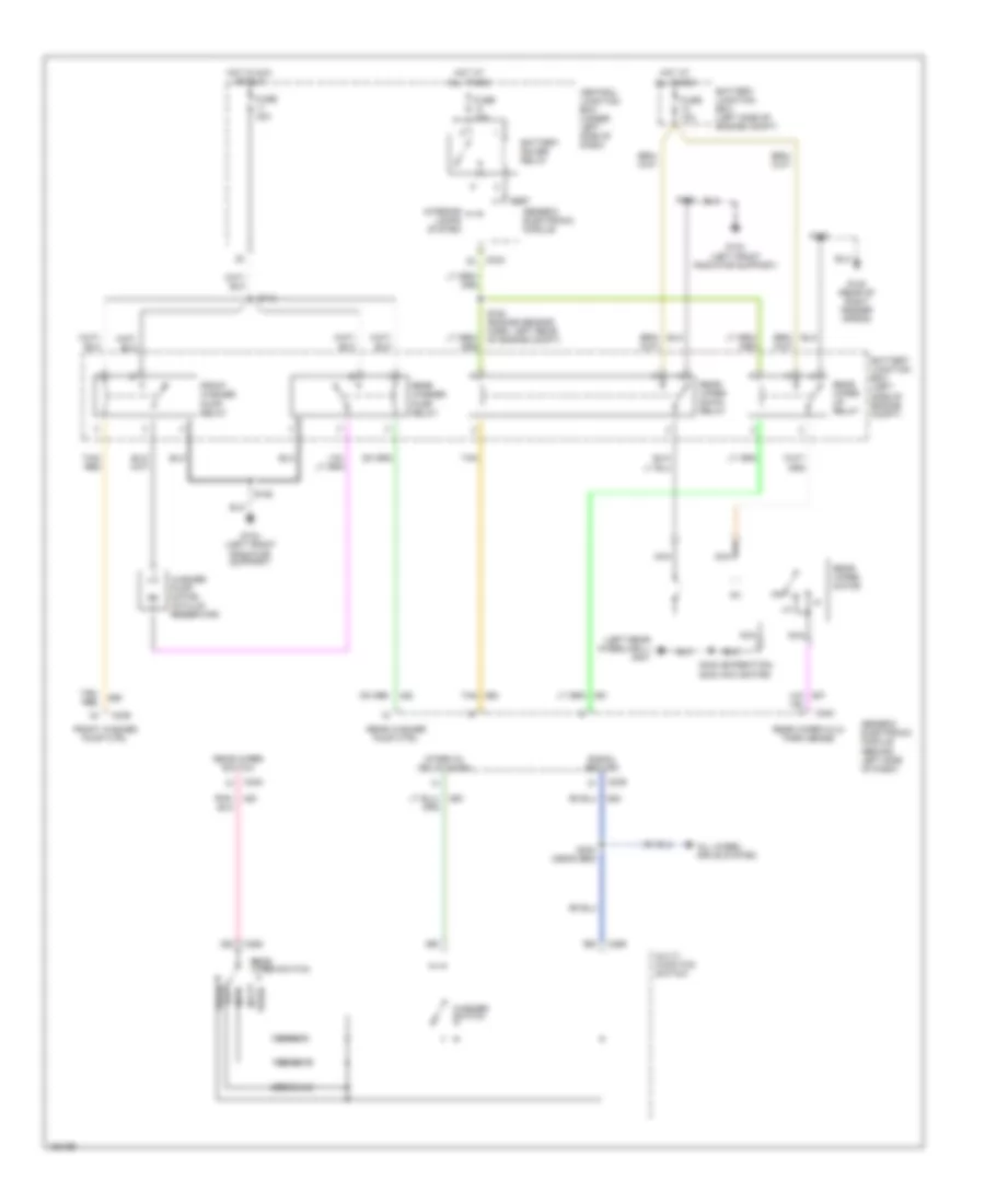
Automatic A/C Wiring Diagram (2 of 3) for Ford Expedition 2002
List of elements for Automatic A/C Wiring Diagram (2 of 3) for Ford Expedition 2002:
- (interior lamp feed harness, near breakout to 12 pin in-line connector, left front of left rear wheelwell) (w/o roof opening panel) (console panel wiring harness, in breakout to front blower switch) (w/roof opening panel)
- (interior lamp feed harness, near breakout to 16 pin in-line connector, left front of left rear wheelwell) (w/o roof opening panel) (console panel wiring harness, near breakout to cd changer) (w/roof opening panel) s352 (w/roof opening panel) s920 (w/o roof opening panel)
- (interior lamp feed harness, near breakout to left side rail lamp) (w/o roof opening panel) (console panel harness, near breakout to rear mode potentiometer) (w/roof opening panel) s340 (w/roof opening panel) s918 (w/o roof opening panel)
- (left rear wheelwell) g402
- (main harness, in breakout to central junction box) s228
- (main harness, near breakout to passenger airbag) s295
- (not used)
- (safety belt retractor harness, near breakout to auxiliary a/c mode switch) s422
- (w/o roof opening panel)
- (w/roof opening panel)
- (w/roof opening panel) (console panel harness, near breakout to rear mode potentiometer) (w/o roof opening panel) (interior lamp feed harness, near breakout to 12 pin in-line connector, left front of left rear wheelwell)
- Anti-lock brakes system
- Auxiliary a/c blend actuator (in rear of vehicle, behind left side panel)
- Auxiliary a/c mode actuator (in rear of vehicle, behind left side panel)
- Battery junction box (on left side of engine compartment)
- C242
- C243
- Central junction box (under left side of dash)
- Console blower relay
- Data link connector (dlc) (partial) (under center of dash)
- Front blend potentiometer (w/o roof opening panel) (in center of headliner) (w/roof opening panel) (in front of floor console)
- Front mode potentiometer (w/o roof opening panel) (in center of headliner) (w/roof opening panel) (in front of floor console)
- Fuse 10a
- Fuse 5a
- Hot in run
- Instrument cluster system
- Pnk/ (main harness, near breakout to passenger air bag) s296
- Powertrain control module (pcm) (on right side of engine compartment)
- Rear blend potentiometer (w/o roof opening panel) (in center of headliner) (w/roof opening panel) (in rear of floor console)
- Rear mode potentiometer
- Red
- Rpo relay block 1 (behind right side of dash, above passenger air bag)
- S2007 (main harness, near breakout to central junction box)
- S2008 (main harness, near breakout to instrument cluster)
- S339 s919
- S930 s921
- Solid state
- Tan/ red
- Wot relay
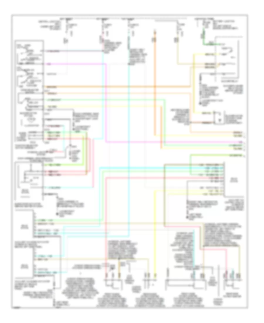
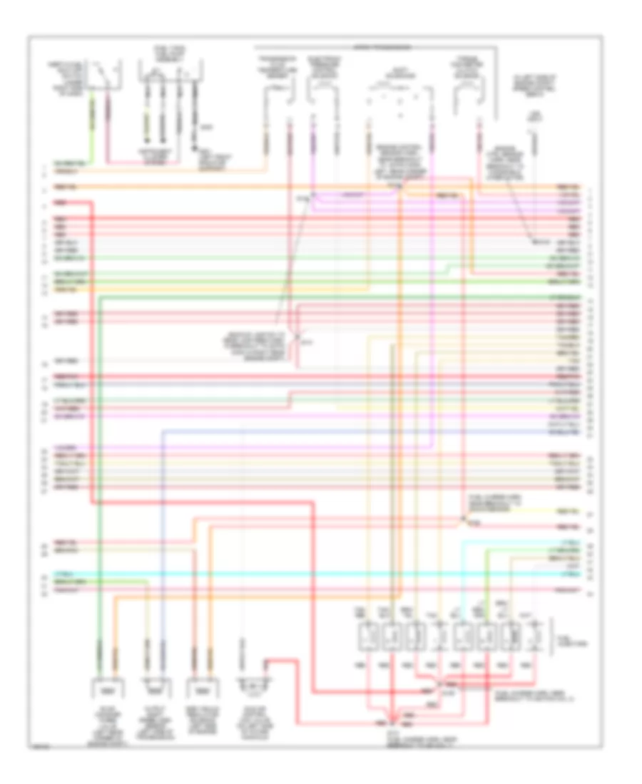
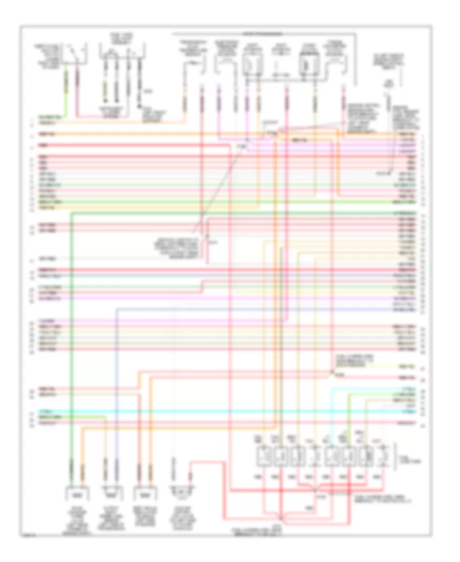
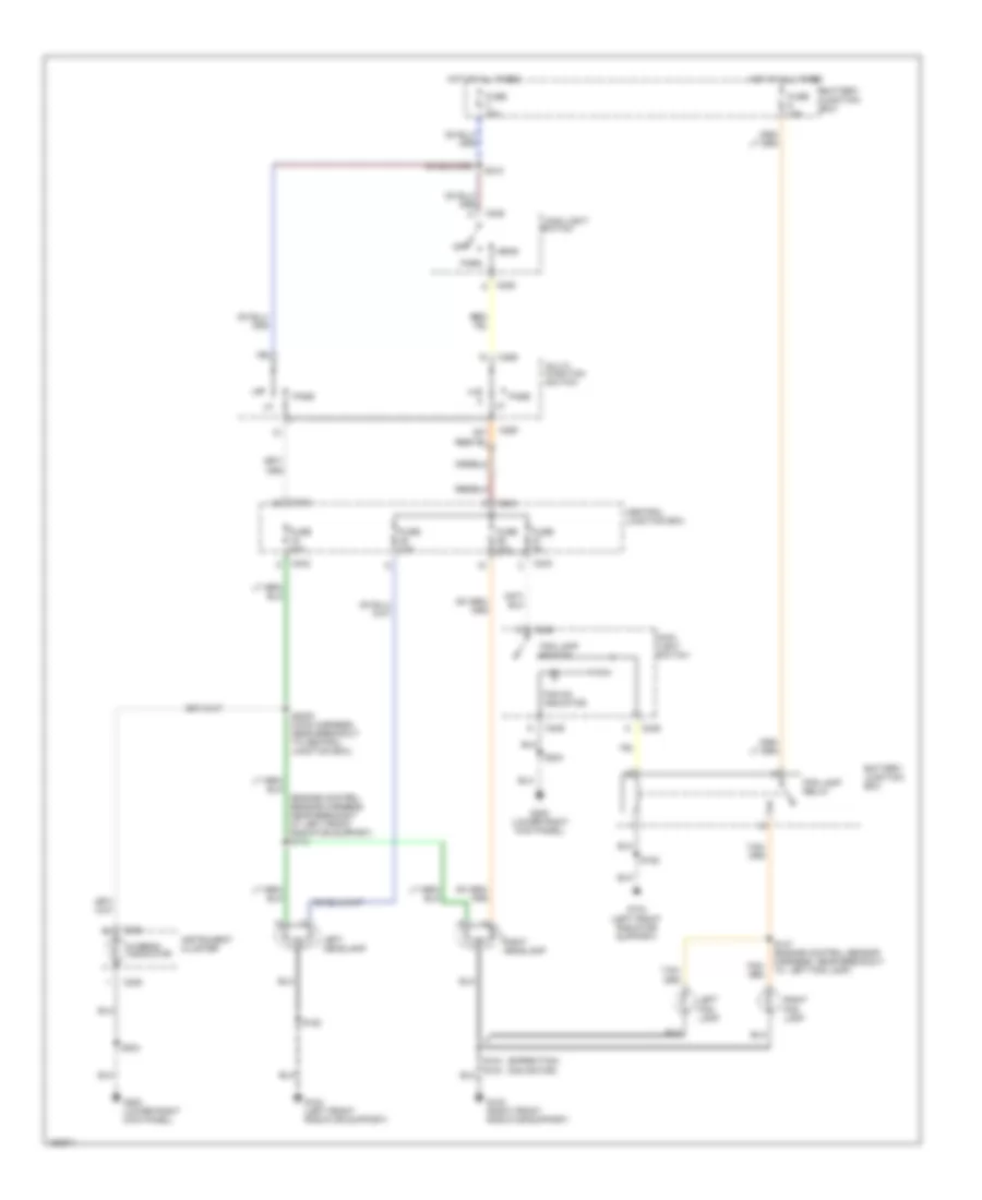
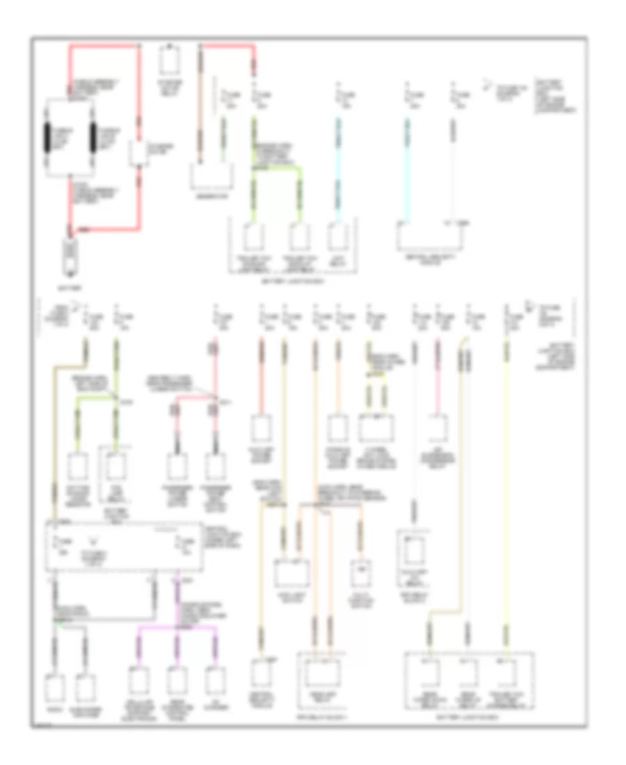
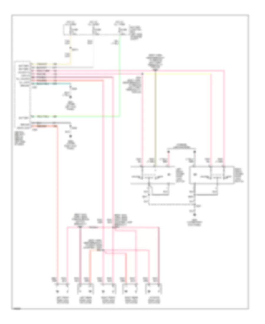
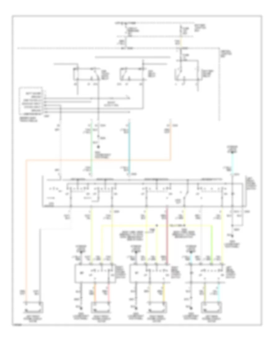
Automatic A/C Wiring Diagram (3 of 3) for Ford Expedition 2002
List of elements for Automatic A/C Wiring Diagram (3 of 3) for Ford Expedition 2002:
- (console panel harness, near breakout to console blower motor) s322
- (engine control sensor harness, near breakout to starter motor relay) s102
- (interior lamp feed harness, near breakout to 3 pin in-line connector, in center of headliner) s923
- (left rear wheelwell) g402
- (lower right kick panel) g200
- (not used)
- (rear of right fender apron) g102
- (safety belt retractor harness, near breakout to driver side impact sensor) s335
- 0.6 ohms
- 2.7 ohms
- 3.8 ohms
- 87a
- A/c clutch cycling pressure switch (in right rear corner of engine compartment)
- A/c clutch diode
- A/c compressor clutch solenoid (in right front of engine compartment)
- A/c pressure cut-off switch (in right side of engine compartment)
- Auxiliary a/c blower motor (in rear of vehicle, behind left side panel)
- Auxiliary a/c blower motor resistor (in rear of vehicle, behind left side panel)
- Auxiliary a/c relay
- Battery junction box (on left side of engine compartment)
- Console blend door actuator (inside left center of floor console)
- Console blower motor (inside center of floor console)
- Console blower motor resistor (in center of floor console)
- Front blower motor switch
- Fuse 30a
- High
- Hot at all times
- Low
- Med
- Off
- Ohms
- Rear
- Rear blower motor switch
- Rear integrated control panel (ricp) (rear blower switch)
- Red/ pnk
- Red/pnk
- Rpo relay block 2 (in front of left rear wheelwell)
- S322 (console panel harness, near breakout to console blower motor)
- S423 (safety belt retractor harness, near breakout to auxiliary a/c mode blower motor resistor assembly)
- S916 (w/o roof opening panel) (interior lamp feed harness, near breakout to left side rail lamp)
- S929 (w/roof opening panel) (console panel harness, in breakout to front blower switch)
- W/o roof opening panel
- W/roof opening panel
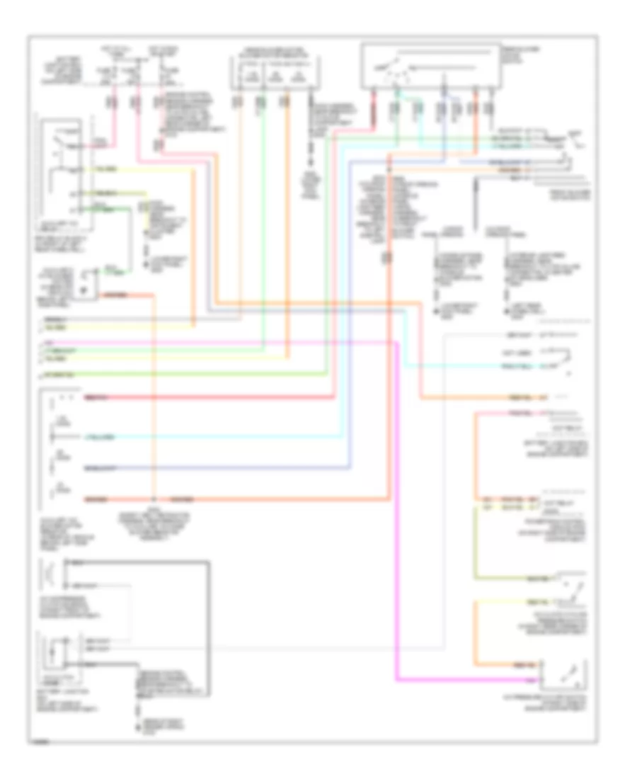
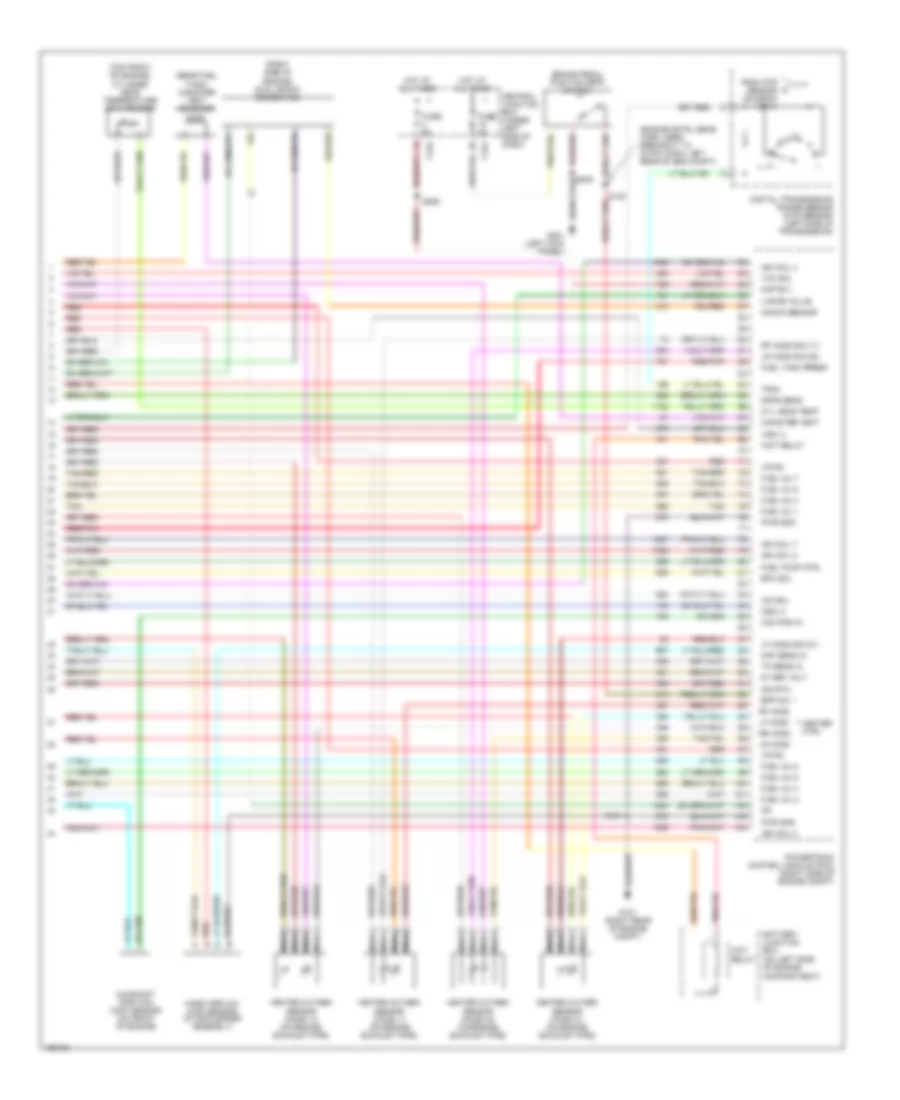
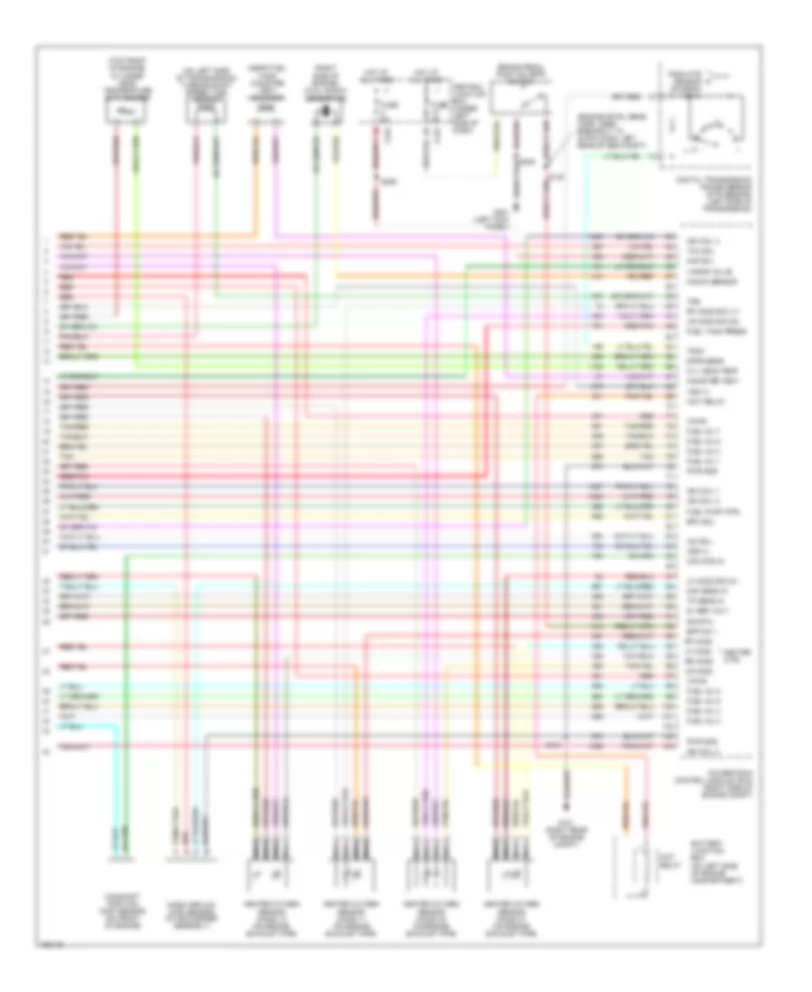
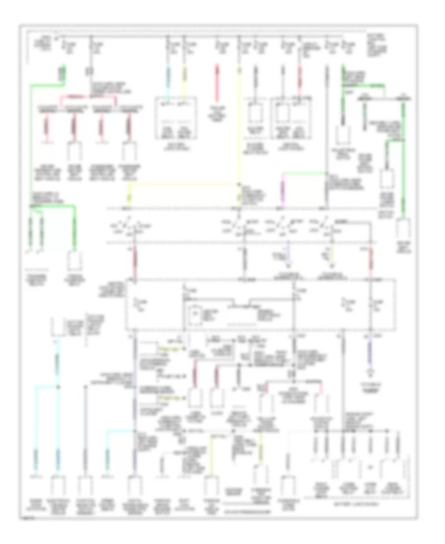
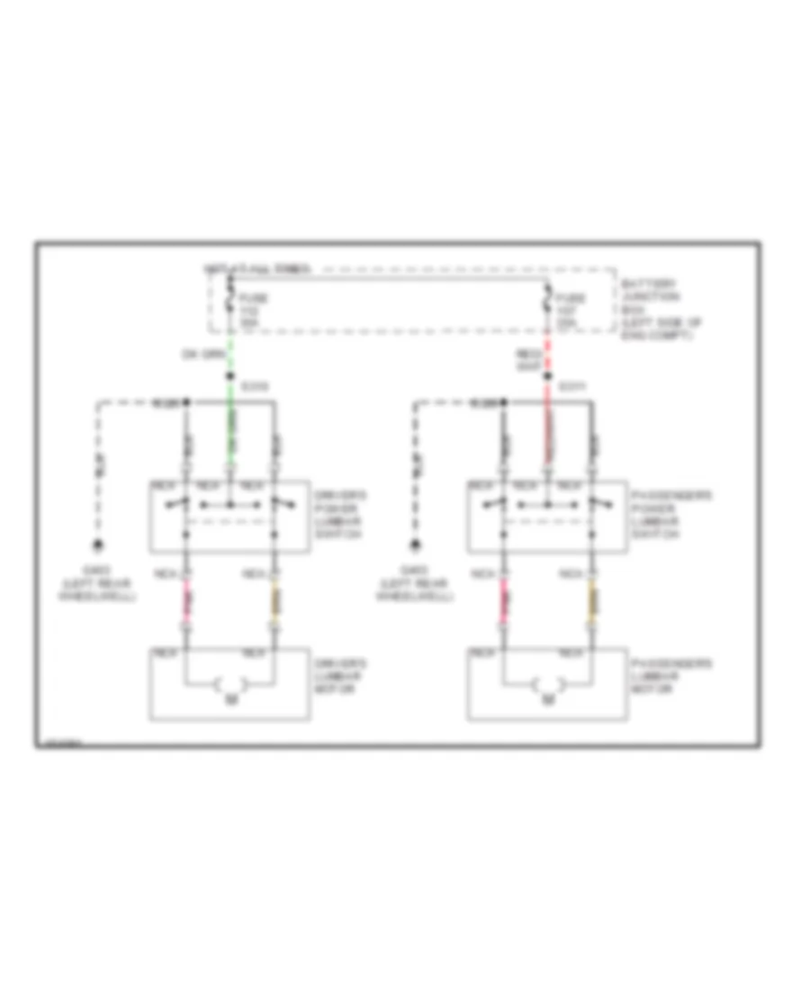
Manual A/C Wiring Diagram (1 of 2) for Ford Expedition 2002
List of elements for Manual A/C Wiring Diagram (1 of 2) for Ford Expedition 2002:
- (heater blower motor feed harness, in breakout to blower motor resistor) s125
- (interior lamp feed harness, near breakout to 12 pin in-line connector, left front of left rear wheelwell) (w/o roof opening panel) (console panel wiring harness, in breakout to front blower switch) (w/roof opening panel)
- (interior lamp feed harness, near breakout to 16 pin in-line connector, left front of left rear wheelwell) (w/o roof opening panel) (console panel wiring harness, near breakout to cd changer) (w/roof opening panel) s352 (w/roof opening panel) s920 (w/o roof opening panel)
- (interior lamp feed harness, near breakout to left side rail lamp) (w/o roof opening panel) (console panel harness, near breakout to rear mode potentiometer) (w/roof opening panel)
- (left rear wheelwell) g402
- (lower right kick panel) g200
- (main harness, near breakout to rpo relay block)
- (safety belt retractor harness, near breakout to auxiliary a/c mode switch) s422
- (w/o roof opening panel)
- (w/roof opening panel)
- (w/roof opening panel) (console panel harness, near breakout to rear mode potentiometer) (w/o roof opening panel) (interior lamp feed harness, near breakout to 12 pin in-line connector, left front of left rear wheelwell)
- (w/roof opening panel) (w/o roof opening panel)
- 87a
- Auxiliary a/c blend actuator (in rear of vehicle, behind left side panel)
- Auxiliary a/c control module (in rear of vehicle, behind left side panel)
- Auxiliary a/c mode actuator (in rear of vehicle, behind left side panel)
- Battery junction box (on left side of engine compartment)
- Blend door actuator (behind center of dash)
- Blend door potent- iometer
- Block)
- Blower motor (on right side of engine compartment)
- Blower motor switch
- Blower relay
- Blower/flasher relay block (behind center of dash)
- C217
- C218
- C219
- C220
- C242
- C243
- Central junction box (under left side of dash)
- Cold
- Def
- Def/flr
- Flasher relay block)
- Floor
- Flr & def
- Front blend potentiometer (w/o roof opening panel) (in center of headliner) (w/roof opening panel) (in front of floor console)
- Front mode potentiometer (w/o roof opening panel) (in center of headliner) (w/roof opening panel) (in front of floor console)
- Function selector switch assembly
- Fuse 23 10a
- Fuse 24 10a
- Fuse 40a
- Fuse 5 15a
- Fuse 5a
- High
- Hot at all times
- Hot in run
- Illumination
- Interior lights system
- Low
- Max a/c
- Med high
- Med low
- Mode selector switch
- Norm a/c
- Off
- Pan & flr
- Pan/flr
- Panel
- Pnk (main harness, near breakout to instrument cluster) s222
- Rear blend potentiometer (w/o roof opening panel) (in center of headliner) (w/roof opening panel) (in rear of floor console)
- Rear mode potentiometer
- Red
- S203
- S339 s919
- S340 s918
- S424 (safety belt retractor harness, near breakout to rpo relay box 2)
- S930 s921
- Solid state
- To rpo relay box 2) s424
- Warm
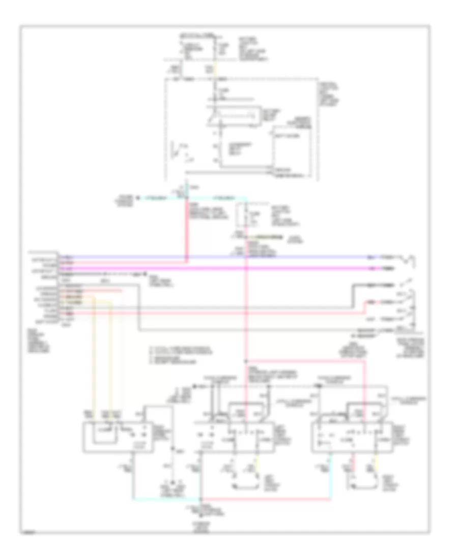
Manual A/C Wiring Diagram (2 of 2) for Ford Expedition 2002
List of elements for Manual A/C Wiring Diagram (2 of 2) for Ford Expedition 2002:
- (console panel harness, near breakout to console blower motor) s322
- (engine control sensor harness, near breakout to 40 pin in-line connector, left rear corner of engine compartment) s134
- (interior lamp feed harness, near breakout to 3 pin in-line connector, in center of headliner) s923
- (left rear wheelwell) g402
- (lower right kick panel) g200
- (main harness, near breakout to glove compartment lamp) s200
- (near blower motor) blower motor resistor
- (not used)
- (rear of right fender apron) g102
- .33 ohms
- .62 ohms
- 1.38 ohms
- 87a
- A/c clutch cycling pressure switch (in right rear corner of engine compartment)
- A/c clutch diode
- A/c compressor clutch solenoid (in right front of engine compartment)
- A/c pressure cut-off switch (in right side of engine compartment)
- Accs
- Auxiliary a/c blower motor (in rear of vehicle, behind left side panel)
- Auxiliary a/c blower motor resistor (in rear of vehicle, behind left side panel)
- Auxiliary a/c relay
- Battery junction box (on left side of engine compartment)
- Front blower motor switch
- Fuse 15a
- Fuse 30a
- G200 (lower right kick panel)
- Harness, near breakout to instrument cluster) s204
- Hot at all times
- Hot in run or start
- Off
- Powertrain control module (pcm) (on right side of engine compartment)
- Rear
- Rear blower motor switch
- Red/pnk
- Rpo relay block 2 (in front of left rear wheelwell)
- S102
- S423 (safety belt retractor harness, near breakout to auxiliary a/c mode blower resistor assembly)
- S916 (w/o roof opening panel) (interior lamp feed harness, near breakout to left side rail lamp)
- S929 (w/roof opening panel) (console panel wiring harness, in breakout to front blower switch)
- W/o roof opening panel
- W/roof panel opening
- Wot relay
ANTI-LOCK BRAKES
Anti-lock Brake Wiring Diagrams for Ford Expedition 2002
List of elements for Anti-lock Brake Wiring Diagrams for Ford Expedition 2002:
- 4-wheel anti-lock brake system (4wabs) module (left side of engine compt)
- 4wabs ind ctrl
- Abs active input
- Active a4wd input
- Anti- lock ind
- Battery junction box (on left side of engine compartment)
- Bias ckt
- Bpp switch feed
- Brake fluid level indicator switch (on brake fluid reservoir)
- Brake fluid level sw
- Brake pedal position (bpp) switch (behind left side of dash)
- C146
- C238
- C240
- C241
- C242
- C243
- Central junction box (under left side of dash)
- Computer data lines system
- Data link connector (behind center of dash)
- Diagnostic circuit
- Differential speed sensor (dss) (on rear axle)
- Fuse 10a
- Fuse 50a
- Fuse 5a
- G104 (left front radiator support)
- G201 (lower left kick panel)
- Generic electronic module (gem)
- Ground
- Hot at all times
- Hot in run
- Ignition feed
- Instrument cluster
- Left front sensor (high)
- Left front sensor (low)
- Left front wheel 4wabs sensor (at wheel)
- Nca
- Ohm
- Power input
- Processor micro-
- Rear sensor (high)
- Rear sensor (low)
- Red/pnk
- Right front sensor (high)
- Right front sensor (low)
- Right front wheel 4wabs sensor (at wheel)
- S105 (engine sensor harn, near breakout to 4wabs module)
- S106
- S107
- S130 (engine sensor harn, left rear corner of engine compartment)
- S156 (engine sensor harn, near breakout to 4wabs module)
- S208 (engine sensor harn, left side of dash)
- S229 (main harness, near breakout to cluster)
- S265
- Tan/red
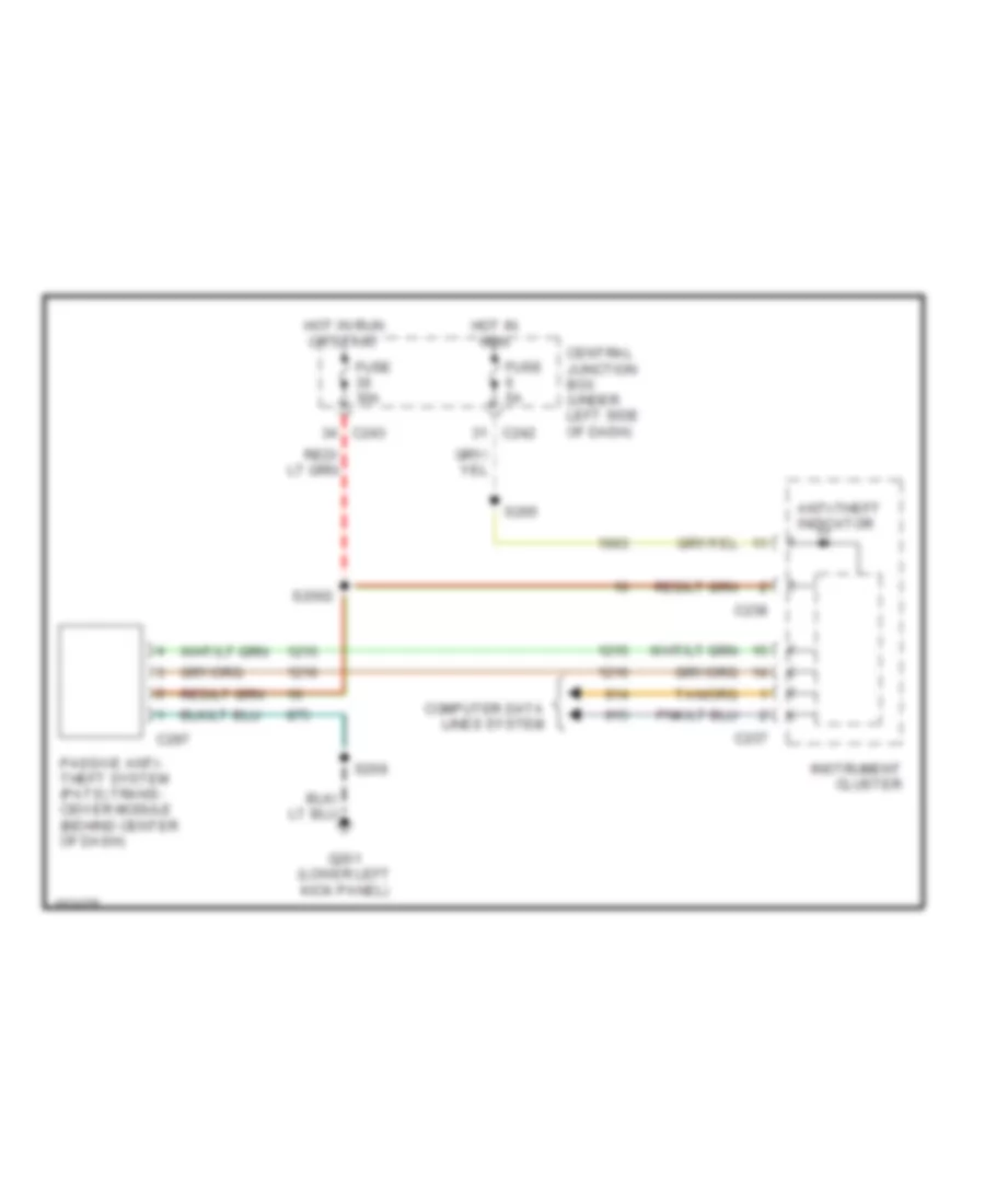
ANTI-THEFT
Forced Entry Wiring Diagram for Ford Expedition 2002
List of elements for Forced Entry Wiring Diagram for Ford Expedition 2002:
- (lower
- (main harn, near gem breakout) s268
- (rear window regulator harness) s401
- (under center of dash) data link connector
- 1/2
- 3/4
- 5/6
- 7/8
- 9/0
- Ajar out
- All lock
- All unlock
- Auto
- Battery
- Battery junction box (left side of engine compt)
- Bpp switch
- Brake pedal position switch
- C239
- C240
- C256
- C257
- Central security module (behind left side of dash)
- Datalink
- Door ajar
- Door ajar in
- Door locks system
- Drvr lock
- Electronic suspension & steering systems
- Ext light in
- Exterior lights system
- Fuse 15a
- Fuse 20a
- Fuse 30a
- Fuse 5a
- G200
- G200 (lower right kick panel)
- G201 (lower left kick panel)
- G401 (left rear wheelwell)
- Generic electronic module (gem) (behind left side of dash)
- Ground
- Hdlmp relay
- Head
- Headlamps system
- Horn in
- Horn out
- Horns system
- Hot at all times
- Hot in run or start
- Ignition
- Illum entry
- Illum in
- Instrument cluster breakout)
- Interior lights system
- Keypad illum
- Keypad switch assembly
- Left front door ajar switch
- Left front power door lock switch
- Left rear door ajar switch
- Liftgate
- Liftgate ajar switch
- Lock
- Lock in
- Main light switch
- Memory seat
- Memory system
- Nca
- Off
- Park
- Rear glass ajar switch
- Red
- Reverse in
- Right front door ajar switch
- Right front power door lock switch
- Right kick panel)
- Right rear door ajar switch
- S2003 (main harn, near instrument cluster breakout)
- S2013
- S225
- S234
- S234 (body harn, near breakout to remote anti-theft personality module)
- S250
- S258
- S402
- S501
- S600
- S701
- S801
- Unlock
- Unlock in
Passive Anti-theft Wiring Diagram for Ford Expedition 2002
List of elements for Passive Anti-theft Wiring Diagram for Ford Expedition 2002:
- Anti-theft indicator
- C237
- C238
- C242
- C243
- C297
- Central junction box (under left side of dash)
- Computer data lines system
- Fuse 30a
- Fuse 5a
- G201 (lower left kick panel)
- Hot in run
- Hot in run or start
- Instrument cluster
- Passive anti- theft system (pats) trans- ceiver module (behind center of dash)
- S2002
- S208
- S265
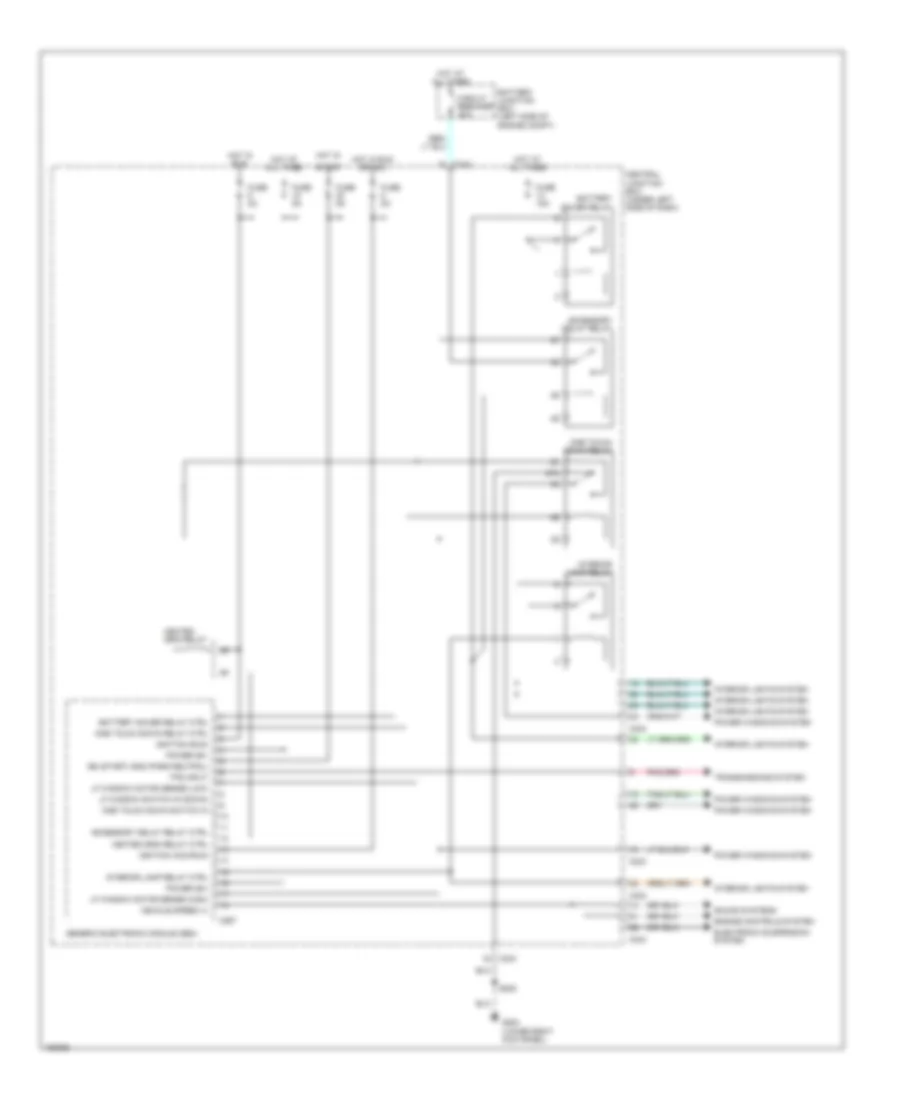
BODY COMPUTER
Body Computer Wiring Diagrams (1 of 2) for Ford Expedition 2002
List of elements for Body Computer Wiring Diagrams (1 of 2) for Ford Expedition 2002:
- 87a
- Accessory delay relay
- Accessory delay relay ctrl
- Battery junction box (left side of engine compt)
- Battery saver relay
- Battery saver relay ctrl
- C242
- C243
- C267
- Central junction box (under left side of dash)
- Circuit breaker 30a
- Electronic suspension system
- Engine controls system
- Fuse 15a
- Fuse 5a
- G200 (lower right kick panel)
- Generic electronic module (gem)
- Heated grid relay
- Heated grid relay ctrl
- Hot at all times
- Hot in
- Hot in run
- Hot in run or acc
- Ign (start) gnd (park/neutral)
- Ignition (acc/run)
- Ignition (run)
- Interior lamp relay
- Interior lamp relay ctrl
- Interior lights system
- Lf window motor sense (high)
- Lf window motor sense (low)
- Lf window switch in (down)
- One touch down relay
- One touch down relay ctrl
- One touch down switch in
- Power (b+)
- Power windows system
- S205
- Sound systems
- Start
- Tps input
- Transmissions system
- Vehicle speed (+)
Body Computer Wiring Diagrams (2 of 2) for Ford Expedition 2002
List of elements for Body Computer Wiring Diagrams (2 of 2) for Ford Expedition 2002:
- (lower left kick panel)
- (park/headlamps on) in
- 4 high to 4 low relay ctrl
- 4 low to 4 high relay ctrl
- 4x4 high range ind ctrl
- 4x4 mode switch in
- A4wd indicator ctrl
- Abs active in
- Air suspension out
- Anti-lock brakes system (abs control module)
- Anti-theft system (rap module)
- Antilock brakes sytem (4wabs module)
- Brake pedal position switch
- C239
- C240
- C241
- Computer data lines system (datalink pin 7)
- Contact plate a in
- Contact plate b in
- Contact plate c in
- Contact plate d in
- Defogger system (rear defogger switch)
- Diagnostic link
- Door ajar indicator ctrl
- Door ajar out
- Electronic suspension system
- Exterior lights system (bpp switch)
- Front shaft speed sensor in
- G201
- Generic electronic module (gem) (behind left side of dash)
- Ground
- Hall effect speed sensor out
- Ignition key warning switch in
- Illuminated entry request in
- Instrument cluster system
- Instrument cluster system (washer fluid level switch)
- Interval delay/wash in
- Lf door ajar switch in
- Liftgate and glass ajar in
- Low washer fluid out
- Lr door ajar switch in
- Rear shaft speed sensor in
- Rear washer pump relay out
- Rear window defrost switch in
- Rear wiper relay ctrl (down)
- Rear wiper relay ctrl (up)
- Rear wiper sense (hi/low/park)
- Rear wiper switch in
- Rf door ajar switch in
- Rr door ajar switch in
- S2021 (main harn, near breakout to belt minder module)
- S2022 (main harn, near breakout to belt minder module)
- S208
- Seat belt indicator ctrl
- Seat belt warning switch in
- Signal return
- Tan
- Tan/red
- Tone request
- Torque on demand relay out
- Trans in neutral in
- Trans low range out
- Transfer case return
- Transmission controls system (4 wheel drive mode switch)
- Transmission controls system (4wd mode switch)
- Transmission controls system (powertrain control module)
- Transmission controls system (torque on demand relay)
- Transmission controls system (transfer case assembly)
- Transmission controls system (transfer case shift relays)
- Transmission controls system (transmission range sensor)
- Warning systems (belt minder module)
- Warning systems (ignition key warning switch)
- Warning systems (lf door ajar switch)
- Warning systems (liftgate & glass ajar switches)
- Warning systems (lr door ajar switch)
- Warning systems (main light switch)
- Warning systems (rf door ajar switch)
- Warning systems (rr door ajar switch)
- Warning systems (seat belt switch)
- Washer fluid level switch in
- Washer pump ctrl
- Wiper hi/lo relay ctrl
- Wiper mode select switch in
- Wiper motor park sense
- Wiper run/park relay ctrl
- Wiper/washer system (hi/lo relay)
- Wiper/washer system (multi-function switch)
- Wiper/washer system (rear washer pump relay)
- Wiper/washer system (rear wiper down relay)
- Wiper/washer system (rear wiper motor)
- Wiper/washer system (rear wiper up relay)
- Wiper/washer system (run/park relay)
- Wiper/washer system (washer pump relay)
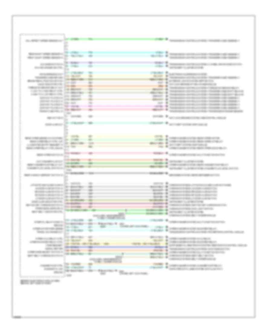
COMPUTER DATA LINES
Computer Data Lines for Ford Expedition 2002
List of elements for Computer Data Lines for Ford Expedition 2002:
- (main harn, near breakout to evo module) s229
- (safety belt harn, near left kick panel) s332
- (under center of dash) data link connector (dlc)
- 4 wheel anti-lock brake system (4wabs) control module (left side of engine compt)
- Air suspension/evo steering module (behind center of dash)
- C146
- C174
- C2005
- C237
- C239
- C242
- C256
- C280
- C296
- C356
- C439
- Central security module (behind left side of dash)
- Driver seat module (under driver seat) (w/memory seat)
- Electronic automatic temperature control module
- Fuse 20a
- G101 (right side of firewall)
- G200 (lower right kick panel)
- Generic electronic module (gem) (behind left side of dash)
- Hot at all times central junction box
- Instrument cluster
- Instrument cluster (xlt)
- Parking aid module (right rear of vehicle)
- Powertrain control module (pcm) (right side of engine compt)
- Restraints control module (rcm) (behind right side of dash)
- S101
- S2005
- S2007 (main harn, near breakout to central junction box)
- S2008 (main harn, near breakout to instrument cluster)
- S202
CRUISE CONTROL
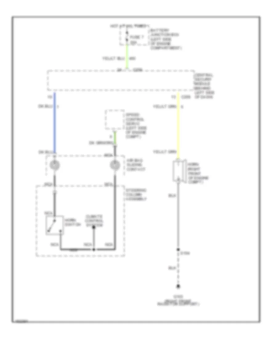
Cruise Control Wiring Diagram for Ford Expedition 2002
List of elements for Cruise Control Wiring Diagram for Ford Expedition 2002:
- (not used)
- Accel
- Air bag sliding contact (top of steering column)
- Battery
- Battery junction box (on left side of eng compt)
- Brake pedal position (bpp) switch (under left side of dash)
- Brake press in
- Brake pressure switch (left rear corner of engine compt)
- C222
- C234
- C242
- C243
- C256
- C292
- Central junction box (under left side of dash)
- Central security module (behind left side of dash)
- Coast
- Control sw gnd
- Control sw in
- Expedition
- Fuse 15a
- Fuse 20a
- Fuse 5a
- G102 (rear of right fender apron)
- G200 (lower left kick panel)
- Ground
- Horn switch
- Horn switch in
- Hot at all times
- Hot in run
- Ign
- Navigator
- Nca
- Off
- Ohms
- Oss sensor
- Output shaft speed (oss) sensor (on left side of transmission)
- Powertrain control module (on right side of engine compartment)
- Resume
- S102
- S112
- S138 (engine sensor harn, right rear of engine compt)
- S143 (engine sensor harn, near breakout to windshield wiper motor)
- S208
- Set/
- Signal return
- Speed control servo (in left side of engine compt)
- Speed control switch assembly
- Steering column assembly
- Vehicle speed input
- Vehicle speed out
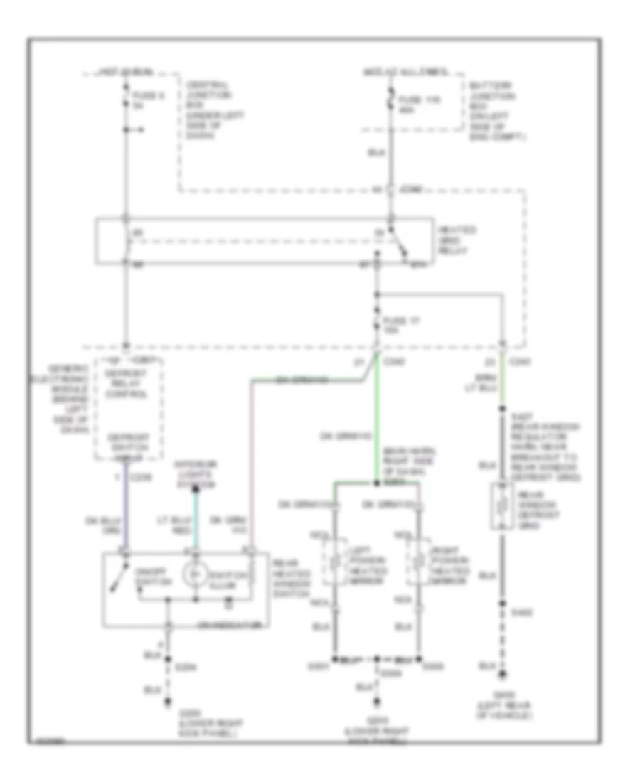
DEFOGGERS
Defogger Wiring Diagram for Ford Expedition 2002
List of elements for Defogger Wiring Diagram for Ford Expedition 2002:
- (main harn, right side of dash) s259
- 87a
- Battery junction box (on left side of eng compt)
- C239
- C242
- C243
- C267
- Central junction box (under left side of dash)
- Defrost relay control
- Defrost switch input
- Fuse 116 40a
- Fuse 17 10a
- Fuse 6 5a
- G200 (lower right kick panel)
- G400 (left rear of vehicle)
- Generic electronic module (behind left side of dash)
- Heated grid relay
- Hot at all times
- Hot in run
- Interior lights system
- Left power/ heated mirror
- Nca
- On indicator
- On/off switch
- Rear heated window switch
- Rear window defrost grid
- Right power/ heated mirror
- S204
- S402
- S427 (rear window regulator harn, near breakout to rear window defrost grid)
- S500
- S501
- S600
- Switch illum
ELECTRONIC POWER STEERING
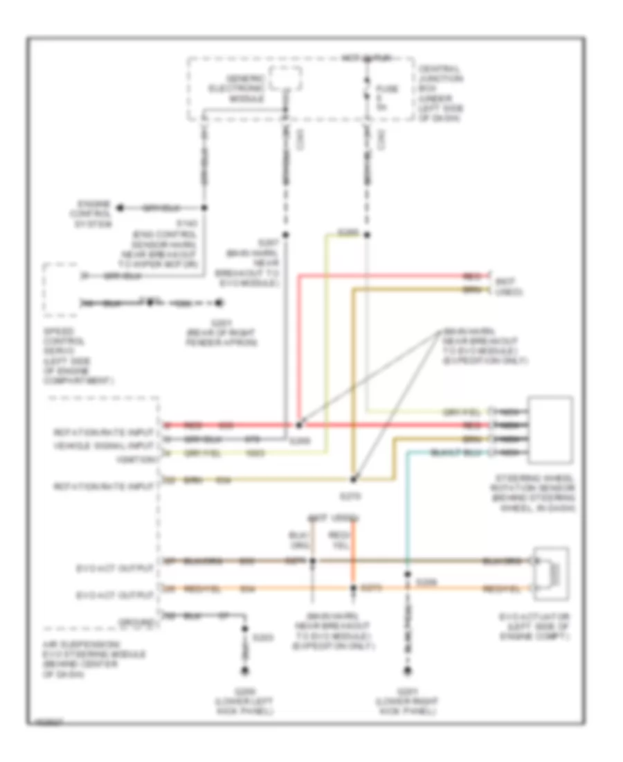
Electronic Power Steering Wiring Diagram, with Air Suspension for Ford Expedition 2002
List of elements for Electronic Power Steering Wiring Diagram, with Air Suspension for Ford Expedition 2002:
- (eng control sensor harn, near breakout to wiper motor)
- (main harn, near breakout to evo module) (expedition only)
- (main harn, near breakout to evo module) (expediton only)
- (not used)
- Air suspension/ evo steering module (behind center of dash)
- C242
- C243
- Central junction box (under left side of dash)
- Engine control system
- Evo act output
- Evo actuator (left side of engine compt)
- Fuse 5a
- G200 (lower left kick panel)
- G201 (lower right kick panel)
- G201 (rear of right fender apron)
- Generic electronic module
- Ground
- Hot in run
- Ignition
- Nca
- Red
- Rotation rate input
- S102
- S143
- S203
- S208
- S265
- S267 (main harn, near breakout to evo module)
- S269
- S270
- S271
- S273
- Speed control servo (left side of engine compartment)
- Steering wheel rotation sensor (behind steering wheel, in dash)
- Vehicle signal input
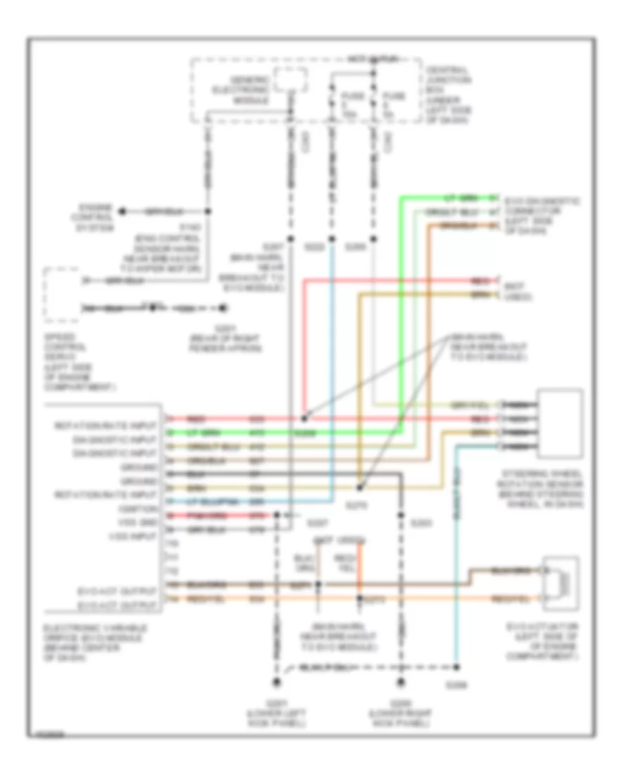
Electronic Power Steering Wiring Diagram, without Air Suspension for Ford Expedition 2002
List of elements for Electronic Power Steering Wiring Diagram, without Air Suspension for Ford Expedition 2002:
- (eng control sensor harn, near breakout to wiper motor)
- (left side of dash)
- (main harn, near breakout to evo module)
- (not used)
- C242
- C243
- Central junction box (under left side of dash)
- Diagnostic input
- Electronic variable orifice (evo) module (behind center of dash)
- Engine control system
- Evo act output
- Evo actuator (left side of of engine compartment)
- Evo diagnostic connector
- Fuse 15a
- Fuse 5a
- G200 (lower right kick panel)
- G201 (lower left kick panel)
- G201 (rear of right fender apron)
- Generic electronic module
- Ground
- Hot in run
- Ignition
- Nca
- Red
- Rotation rate input
- S102
- S143
- S203
- S207
- S208
- S222
- S265
- S267 (main harn, near breakout to evo module)
- S269
- S270
- S271 s271
- S273
- Speed control servo (left side of engine compartment)
- Steering wheel rotation sensor (behind steering wheel, in dash)
- Vss gnd
- Vss input
ELECTRONIC SUSPENSION
Electronic Suspension Wiring Diagram (1 of 2) for Ford Expedition 2002
List of elements for Electronic Suspension Wiring Diagram (1 of 2) for Ford Expedition 2002:
- (main harn, near breakout to air susp/evo mod) s272
- Air suspension compressor motor and vent solenoid (right radiator support)
- Air suspension compressor relay (near right headlamp)
- Air suspension indicator
- Air suspension service switch (under right side of dash)
- Air suspension/ evo steering module (behind center of dash)
- All wheel drv
- Battery junction box (left side of engine compt)
- Bpp switch
- C238
- C242
- C243
- C295
- C296
- Central junction box (under left side of dash)
- Comp mtr vent sol
- Compressor relay
- Computer data lines system
- Data link conn
- Data link connector (under center of dash)
- Evo module
- Front air fill solenoid (near trans cooler)
- Front fill sol
- Front gate sol
- Front gate solenoid (front of a/c condenser)
- Front height sen
- Fuse 15a
- Fuse 50a
- Fuse 5a
- G103 (right front radiator support)
- G104 (left front radiator support)
- G200 (lower right kick panel)
- G201 (lower left kick panel)
- Gem input
- Ground
- Height sen power
- Hot at all times
- Hot in run
- Hot in start
- Instrument cluster
- Left air spring solenoid (in front rear of left wheel)
- Lr spring sol
- Memory systems
- Pcm
- Pnk
- Power (hot in run)
- Power (start)
- Rear air fill solenoid (in front of left rear wheel)
- Rear fill sol
- Rear height sen
- Red
- Right air spring solenoid (in front of right rear wheel)
- Rr spring sol
- S104
- S155
- S177
- S2009
- S265
- S289
- S400
- Service switch
- Solid state
- Steering sensor
- Tan
- Transmission controls
- Vehicl speed (+)
- Warning indicator
Electronic Suspension Wiring Diagram (2 of 2) for Ford Expedition 2002
List of elements for Electronic Suspension Wiring Diagram (2 of 2) for Ford Expedition 2002:
- (lower left kick panel)
- (lower left kick panel) g200
- (main harn, near breakout to air susp/evo mod) s270
- (main harn, near breakout to air susp/evo module) s267
- (main harn, near breakout to evo module)
- (not used)
- (rear lamp harn, near breakout to front height sensor)
- (rear lamp harn, near breakout to front height sensor) s410
- Brake pedal position (bpp) switch (under left side of dash)
- Breakout to inst cluster)
- C174
- C240
- C241
- C256
- Central junction box (under left side of dash)
- Central security module (behind left side of dash)
- Electronic variable orifice (evo) actuator (left side of engine compt)
- Electronic variable orifice (evo) diagnostic connector (under left side of dash)
- Expedition only
- Front height sensor (behind left running board)
- Fuse 5a
- G105 (rear of right fender apron)
- G200
- Generic electronic (gem) module (behind left side of dash)
- Generic electronic module (gem)
- Hot at all times
- Instrument cluster, navigation
- Nca
- Powertrain control module (pcm) (right side of engine compt)
- Rear height sensor (rear floor panel)
- Red
- S102
- S208
- S268 (main harn, near breakout to evo module)
- S269
- S271 (main harn, near breakout to evo module)
- S273
- S409
- Speed control servo (left side of engine compt)
- Steering wheel rotation sensor (behind steering wheel, in dash)
- Tan
ENGINE PERFORMANCE
4.6L
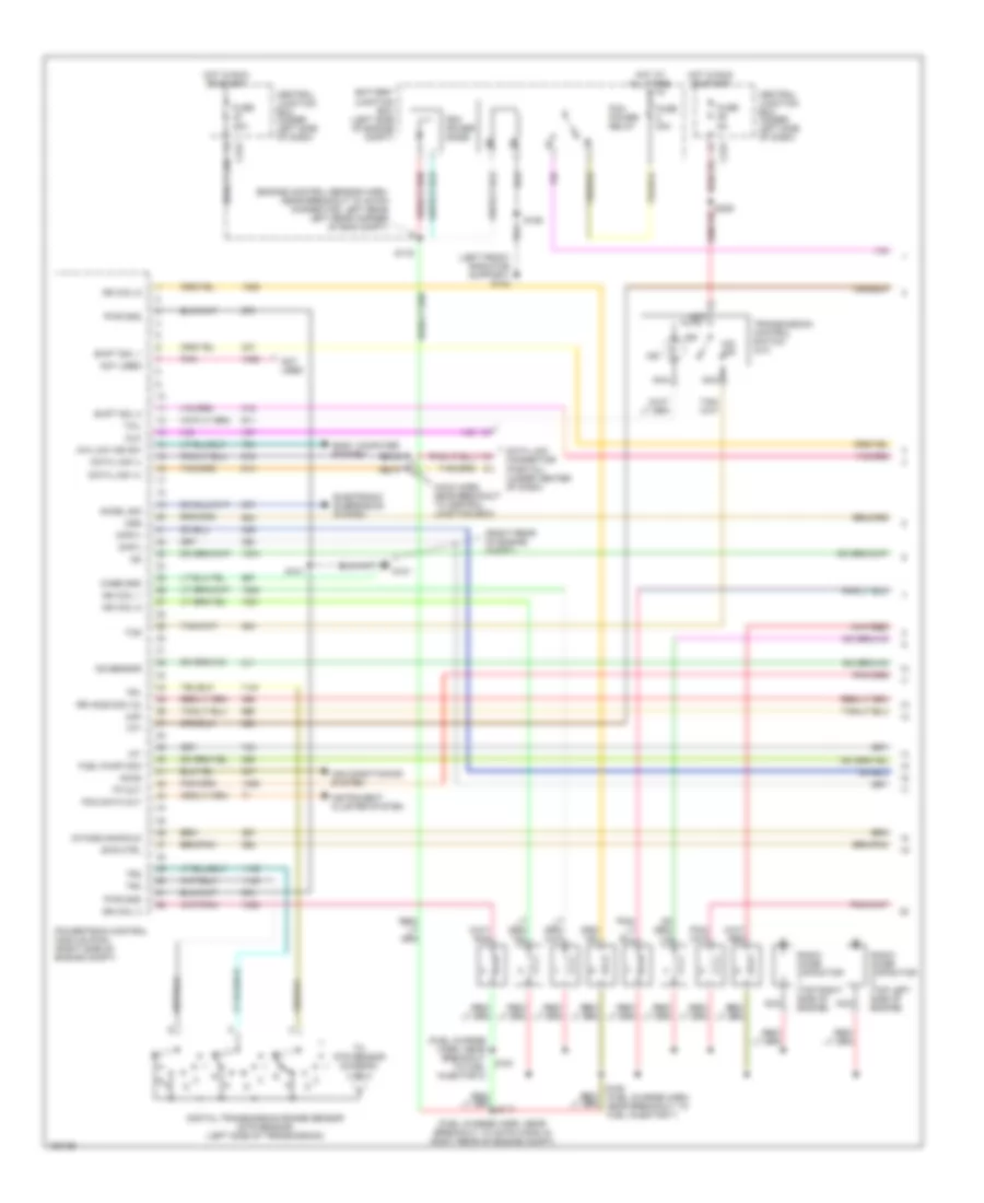
4.6L, Engine Performance Wiring Diagrams, with 4R100 Transmission (1 of 4) for Ford Expedition 2002
List of elements for 4.6L, Engine Performance Wiring Diagrams, with 4R100 Transmission (1 of 4) for Ford Expedition 2002:
- (engine control sensor harn, near breakout to 40-pin connector, left rear left rear corner of eng compt)
- (fuel charge harn, near breakout to 42-pin conn in right rear of engine compt)
- (fuel charge harn, near breakout to fuel injector 3)
- (left front radiator support) g104
- (main harn, near breakout to central junction box)
- (right rear of engine compt)
- 4x4 low ind sw
- Accel sig
- Accs
- Air conditioning system
- Battery junction box (left side of engine compt)
- Body computer system
- Case gnd
- Central junction box (under left side of dash)
- Ckp(+)
- Ckp(-)
- Css
- Data link (+)
- Data link (-)
- Data link connector (partial) (under center of dash)
- Digital transmission range sensor (dtr sensor) (left side of transmission)
- Dlc
- Electronic suspension system
- Evr ctrl
- Fuel pump mon
- Fuse 30a
- Fuse 5a
- G101
- Hot at all times
- Hot in run or start
- Iat
- Ign coil 1
- Ign coil 3
- Ign coil 5
- Ign coil 6
- Ind
- Instrument cluster system
- Intake manifold
- Ks sensor
- Maf
- Nca
- Not used
- Noy used
- O/d off
- Pcm data out
- Pcm power diode
- Pcm power relay
- Pnk
- Powertrain control module (pcm) (right side of engine compt)
- Pwr gnd
- R n
- Radio noise capacitor (top left side of engine)
- Radio noise capacitor (top right side of engine)
- Rr ho2s sig (12)
- S101
- S106
- S116
- S161
- S162 (fuel charge harn, near breakout to fuel injector 7)
- S2007
- S2008
- Shift sol 1
- Shift sol 2
- Tcil
- Tcs
- Tft
- To dtr sensor (diagram 4 of 4)
- Tp out
- Tr1
- Tr2
- Tr4
- Transmission control switch (a/t)
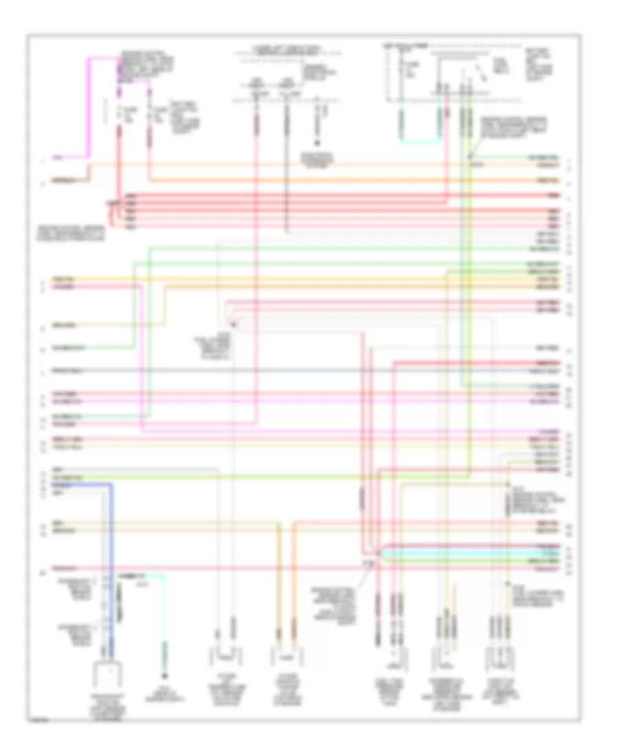
4.6L, Engine Performance Wiring Diagrams, with 4R100 Transmission (2 of 4) for Ford Expedition 2002
List of elements for 4.6L, Engine Performance Wiring Diagrams, with 4R100 Transmission (2 of 4) for Ford Expedition 2002:
- (engine control sensor harn, near breakout to 38-pin conn in right rear of engine compt)
- (engine control sensor harn, near breakout to 40-pin conn in left rear of engine compt)
- (engine control sensor harn, near breakout to windshield wiper motor)
- (under left side of dash) central junction box
- Battery junction box (left side of engine compt)
- C267
- Crankshaft position (ckp) sensor (lower front of engine)
- Crankshaft position sensor shield
- Differential pressure feedback egr (dpfe) sensor (left side of engine)
- Electronic suspension system
- Fuel pump relay
- Fuel tank pressure sensor (in fuel tank)
- Fuse 15a
- Fuse 20a
- G101 (rear of engine compt)
- Generic electronic module
- Hot at all times
- Intake air temperature (iat) sensor (on intake manifold)
- Intake manifold tunning valve (top front of engine)
- Nca
- Red
- Red/pnk
- S101
- S127
- S135 (fuel charge harn, near breakout to ho2s 21)
- S136 (fuel charge harn, near breakout to knock sensor)
- S137 (engine control sensor harn, near breakout to starter relay)
- S138
- S139
- Throttle position (tp) sensor (on throttle body)
- Vss input
4.6L, Engine Performance Wiring Diagrams, with 4R100 Transmission (3 of 4) for Ford Expedition 2002
List of elements for 4.6L, Engine Performance Wiring Diagrams, with 4R100 Transmission (3 of 4) for Ford Expedition 2002:
- (backup lamp sw to rear lamp feed harn, in breakout to 38-pin conn in right rear engine compt)
- (engine control sensor harn, left rear corner
- (engine ctrl sensor harn, near breakout to windsheild wiper motor)
- (fuel charge harn, near breakout to ignition coil 3)
- (fuel charge harn, near breakout to knock sensor)
- (fuel tank) fuel pump assembly
- (in left side of engine compt) speed control servo
- 4r100 transmission
- Coast clutch solenoid
- Egr vacuum regulator solenoid (left side of engine)
- Electronic pressure control solenoid
- Evap canister purge
- Fuel injectors
- G104 (left front radiator support)
- Idle air control (iac) valve (on left side of intake manifold)
- Inertia fuel shut-off switch (under right side of dash)
- Instrument cluster system
- Nca
- Of engine compt)
- Output shaft speed (oss) sensor (left side of transmission)
- Red
- Red/pnk
- S129
- S131 (fuel charge harn, near breakout to ign coil 7)
- S134
- S140
- S141
- S143
- S198
- S400
- Shift solenoid a
- Shift solenoid b
- Tan
- Tan/ red
- Tan/red
- Torque converter clutch solenoid
- Transmission fluid temperature sensor
- Turbine shaft speed (oss) sensor (left side of transmission)
- Valve (left rear corner of engine compt)
- Vss input
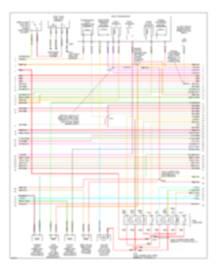
4.6L, Engine Performance Wiring Diagrams, with 4R100 Transmission (4 of 4) for Ford Expedition 2002
List of elements for 4.6L, Engine Performance Wiring Diagrams, with 4R100 Transmission (4 of 4) for Ford Expedition 2002:
- (engine cntrl sens harn, near breakout to 40-pin conn, left rear of eng compt)
- (near fuel tank) canister vent solenoid
- (on left side of engine compartment)
- (right side of engine) dual knock sensor (ks)
- (top front of engine) cylinder head temperature (cht) sensor
- 5v ref volt
- Battery junction box
- Bpp sw
- Brake pedal position (bpp) switch
- Cam pos in
- Camshaft position (cmp) sensor (on front of engine)
- Canister vent
- Central junction box (under left side of dash)
- Cyl head temp
- Digital transmission range sensor (dtr sensor) (left side of transmission)
- Dpfe sens
- Epc sol
- From dtr sensor (diagram 1 of 4)
- Fuel inj 1
- Fuel inj 2
- Fuel inj 3
- Fuel inj 4
- Fuel inj 5
- Fuel inj 6
- Fuel inj 7
- Fuel inj 8
- Fuel pump ctrl
- Fuel tank press
- Fuse 5a
- G101 (right rear of engine compt)
- G201 (left kick panel)
- Heated oxygen sensor (ho2s) 11 (on engine exhaust pipe)
- Heated oxygen sensor (ho2s) 12 (on engine exhaust pipe)
- Heated oxygen sensor (ho2s) 21 (on engine exhaust pipe)
- Heated oxygen sensor (ho2s) 22 (on engine exhaust pipe)
- Heater ctrl
- Hot at all times
- Iac sol
- Ign coil 2
- Ign coil 4
- Ign coil 7
- Ign coil 8
- Kap b(+)
- Knock sensor
- Lf ho2s
- Lf ho2s sig (21)
- Lr ho2s
- Lr ho2s sig (22)
- Maf sens in
- Mass airflow (maf) sensor (in air cleaner assembly)
- Nca
- Oss (+)
- Powertrain control module (pcm) (right side of engine compt)
- Pwr gnd
- Red
- Red/pnk
- Rf ho2s
- Rf ho2s sig (11)
- Rr ho2s
- S101
- S289
- Sig rtn
- Tan
- Tan/red
- Tcc sol
- Tp sens in
- Tr3a
- Tss
- Vapor valve
- Vpwr
- Vss (+)
- Wot relay
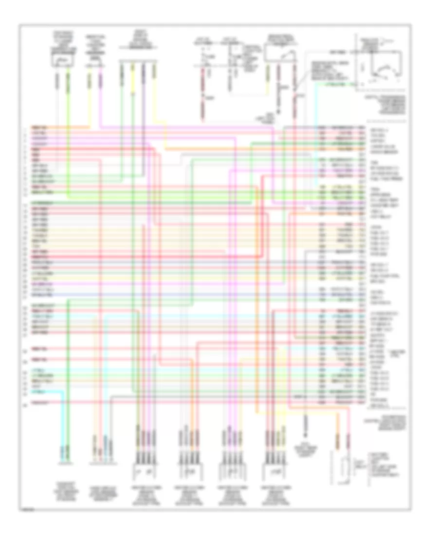
4.6L, Engine Performance Wiring Diagrams, with 4R70W Transmission (1 of 4) for Ford Expedition 2002
List of elements for 4.6L, Engine Performance Wiring Diagrams, with 4R70W Transmission (1 of 4) for Ford Expedition 2002:
- (engine control sensor harn, near breakout to 40-pin connector, left rear corner of eng compt)
- (fuel charge harn, near breakout to 42-pin conn in right rear of engine compt)
- (fuel charge harn, near breakout to fuel injector 3)
- (left front radiator support) g104
- (main harn, near breakout to central junction box)
- (right rear of engine compt)
- 4x4 low ind sw
- Accel sig
- Accs
- Air conditioning system
- Battery junction box (left side of engine compt)
- Body computer system
- Case gnd
- Central junction box (under left side of dash)
- Ckp(+)
- Ckp(-)
- Data link (+)
- Data link (-)
- Data link connector (partial) (under center of dash)
- Digital transmission range sensor (dtr sensor) (left side of transmission)
- Dlc
- Electronic suspension system
- Evr ctrl
- Fuel pump mon
- Fuse 30a
- Fuse 5a
- G101
- Hot at all times
- Hot in run or start
- Iat
- Ign coil 1
- Ign coil 3
- Ign coil 5
- Ign coil 6
- Ind
- Instrument cluster system
- Intake manifold
- Ks sensor
- Maf
- Nca
- Not used
- O/d off
- Pcm data out
- Pcm power diode
- Pcm power relay
- Pnk
- Powertrain control module (pcm) (right side of engine compt)
- Pwr gnd
- R n
- Radio noise capacitor (top left side of engine)
- Radio noise capacitor (top right side of engine)
- Rr ho2s sig (12)
- S101
- S106
- S116
- S161
- S162 (fuel charge harn, near breakout to fuel injector 7)
- S2007
- S2008
- Shift sol 1
- Shift sol 2
- Tcil
- Tcs
- Tft
- To dtr sensor (diagram 4 of 4)
- Tp out
- Tr1
- Tr2
- Tr4
- Transmission control switch (a/t)
4.6L, Engine Performance Wiring Diagrams, with 4R70W Transmission (2 of 4) for Ford Expedition 2002
List of elements for 4.6L, Engine Performance Wiring Diagrams, with 4R70W Transmission (2 of 4) for Ford Expedition 2002:
- (engine control sensor harn, near breakout to 38-pin conn in right rear of engine compt)
- (engine control sensor harn, near breakout to 40-pin conn in left rear of engine compt)
- (engine control sensor harn, near breakout to windshield wiper motor)
- (under left side of dash) central junction box
- Battery junction box (left side of engine compt)
- C267
- Crankshaft position (ckp) sensor (lower front of engine)
- Crankshaft position sensor shield
- Differential pressure feedback egr (dpfe) sensor (left side of engine)
- Electronic suspension system
- Fuel pump relay
- Fuel tank pressure sensor (in fuel tank)
- Fuse 15a
- Fuse 20a
- G101 (rear of engine compt)
- Generic electronic module
- Hot at all times
- Intake air temperature (iat) sensor (on intake manifold)
- Intake manifold tunning valve (top front of engine)
- Nca
- Red
- Red/pnk
- S101
- S127
- S135 (fuel charge harn, near breakout to ho2s 21)
- S136 (fuel charge harn, near breakout to knock sensor)
- S137 (engine control sensor harn, near breakout to starter relay)
- S138
- S139
- Throttle position (tp) sensor (on throttle body)
- Vss input
4.6L, Engine Performance Wiring Diagrams, with 4R70W Transmission (3 of 4) for Ford Expedition 2002
List of elements for 4.6L, Engine Performance Wiring Diagrams, with 4R70W Transmission (3 of 4) for Ford Expedition 2002:
- (backup lamp sw to rear lamp feed harn, in breakout to 38-pin conn in right rear engine compt)
- (engine control sensor harn, near breakout to 40-pin conn, left rear corner of engine compt)
- (engine ctrl sensor harn, near breakout to windshield wiper motor)
- (fuel charge harn, near breakout to ignition coil 3)
- (fuel charge harn, near breakout to knock sensor)
- (fuel tank) fuel pump assembly
- (in left side of engine compt) speed control servo
- 4r70w transmission
- Egr vacuum regulator solenoid (left side of engine)
- Electronic pressure control solenoid
- Evap canister purge
- Fuel injectors
- G201 (left front radiator support)
- Idle air control (iac) valve (on left side of intake manifold)
- Inertia fuel shut-off switch (under right side of dash)
- Instrument cluster system
- Nca
- Output shaft speed (oss) sensor (left side of transmission)
- Red
- Red/pnk
- S129
- S131 (fuel charge harn, near breakout to ign coil 7)
- S134
- S140
- S141
- S143
- S198
- S400
- Shift solenoids
- Tan
- Tan/ red
- Tan/red
- Torque converter clutch solenoid
- Transmission fluid temperature sensor
- Valve (left rear corner of engine compt)
- Vss input
4.6L, Engine Performance Wiring Diagrams, with 4R70W Transmission (4 of 4) for Ford Expedition 2002
List of elements for 4.6L, Engine Performance Wiring Diagrams, with 4R70W Transmission (4 of 4) for Ford Expedition 2002:
- (engine cntrl sens harn, near breakout to 40-pin conn, left rear of eng compt)
- (near fuel tank) canister vent solenoid
- (on left side of engine compartment)
- (right side of engine) dual knock sensor (ks)
- (top front of engine) cylinder head temperature (cht) sensor
- 5v ref volt
- Battery junction box
- Bpp sw
- Brake pedal position (bpp) switch
- Cam pos in
- Camshaft position (cmp) sensor (on front of engine)
- Canister vent
- Central junction box (under left side of dash)
- Cyl head temp
- Digital transmission range sensor (dtr sensor) (left side of transmission)
- Dpfe sens
- Epc sol
- From dtr sensor (diagram 1 of 4)
- Fuel inj 1
- Fuel inj 2
- Fuel inj 3
- Fuel inj 4
- Fuel inj 5
- Fuel inj 6
- Fuel inj 7
- Fuel inj 8
- Fuel pump ctrl
- Fuel tank press
- Fuse 5a
- G101 (right rear of engine compt)
- G201 (left kick panel)
- Heated oxygen sensor (ho2s) 11 (on engine exhaust pipe)
- Heated oxygen sensor (ho2s) 12 (on engine exhaust pipe)
- Heated oxygen sensor (ho2s) 21 (on engine exhaust pipe)
- Heated oxygen sensor (ho2s) 22 (on engine exhaust pipe)
- Heater ctrl
- Hot at all times
- Iac sol
- Ign coil 2
- Ign coil 4
- Ign coil 7
- Ign coil 8
- Kap b(+)
- Knock sensor
- Lf ho2s
- Lf ho2s sig (21)
- Lr ho2s
- Lr ho2s sig (22)
- Maf sens in
- Mass airflow (maf) sensor (in air cleaner assembly)
- Nca
- Oss (+)
- Powertrain control module (pcm) (right side of engine compt)
- Pwr gnd
- Red
- Red/pnk
- Rf ho2s
- Rf ho2s sig (11)
- Rr ho2s
- S101
- S289
- Sig rtn
- Tan
- Tan/red
- Tcc sol
- Tp sens in
- Tr3a
- Vapor valve
- Vpwr
- Vss (+)
- Wot relay
5.4L
5.4L, Engine Performance Wiring Diagrams (1 of 4) for Ford Expedition 2002
List of elements for 5.4L, Engine Performance Wiring Diagrams (1 of 4) for Ford Expedition 2002:
- (engine control sensor harn, near breakout to 40-pin connector, left rear corner of eng compt)
- (fuel charge harn, near breakout to 42-pin conn in right rear of engine compt)
- (fuel charge harn, near breakout to fuel injector 3)
- (left front radiator support) g104
- (main harn, near breakout to central junction box)
- (right rear of engine compt)
- 4x4 low ind sw
- Accel sig
- Accs
- Air conditioning system
- Battery junction box (left side of engine compt)
- Body computer system
- Case gnd
- Ccs
- Central junction box (under left side of dash)
- Ckp(+)
- Ckp(-)
- Data link (+)
- Data link (-)
- Data link connector (partial) (under left side of dash)
- Digital transmission range sensor (dtr sensor) (left side of transmission)
- Dlc
- Electronic suspension system
- Evr ctrl
- Fuel pump mon
- Fuse 30a
- Fuse 5a
- G101
- Hot at all times
- Hot in run or start
- Iat
- Ign coil 1
- Ign coil 3
- Ign coil 5
- Ign coil 6
- Ignition coils
- Ind
- Instrument cluster system
- Intake manifold
- Ks sensor
- Maf
- Nca
- Not used
- O/d off
- Pcm data out
- Pcm power diode
- Pcm power relay
- Pnk
- Powertrain control module (pcm) (right side of engine compt)
- Pwr gnd
- R n
- Radio noise capacitor (top right side of engine)
- Rr ho2s sig (12)
- S100
- S106
- S116
- S161
- S162 (fuel charge harn, near breakout to fuel injector 7)
- S2007
- S2008
- Shift sol 1
- Shift sol 2
- Tcil
- Tcs
- Tft
- To dtr sensor (diagram 4 of 4)
- Tp out
- Tr1
- Tr2
- Tr4
- Transmission control switch (a/t)
5.4L, Engine Performance Wiring Diagrams (2 of 4) for Ford Expedition 2002
List of elements for 5.4L, Engine Performance Wiring Diagrams (2 of 4) for Ford Expedition 2002:
- (engine control sensor harn, near breakout to 38-pin conn in right rear of engine compt)
- (engine control sensor harn, near breakout to 40-pin conn in left rear of engine compt)
- (engine control sensor harn, near breakout to windshield wiper motor)
- (under left side of dash) central junction box
- Battery junction box (left side of engine compt)
- C267
- Crankshaft position (ckp) sensor (lower front of engine)
- Crankshaft position sensor shield
- Differential pressure feedback egr (dpfe) sensor (left side of engine)
- Electronic suspension system
- Fuel pump relay
- Fuel tank pressure sensor (in fuel tank)
- Fuse 15a
- Fuse 20a
- G101 (rear of engine compt)
- Generic electronic module
- Hot at all times
- Intake air temperature (iat) sensor (on intake manifold)
- Intake manifold tuning valve (top front of engine)
- Nca
- Red
- Red/pnk
- S101
- S127
- S135 (fuel charge harn, near breakout to ho2s 21)
- S136 (fuel charge harn, near breakout to knock sensor)
- S137 (engine control sensor harn, near breakout to starter relay)
- S138
- S139
- Throttle position (tp) sensor (on throttle body)
- Vss input
5.4L, Engine Performance Wiring Diagrams (3 of 4) for Ford Expedition 2002
List of elements for 5.4L, Engine Performance Wiring Diagrams (3 of 4) for Ford Expedition 2002:
- (backup lamp sw to rear lamp feed harn, in breakout to 38-pin conn in right rear engine compt)
- (engine control sensor harn, near breakout to 40-pin conn, left rear
- (engine ctrl sensor harn, near breakout to windshield wiper motor)
- (fuel charge harn, near breakout to ignition coil 3)
- (fuel charge harn, near breakout to knock sensor)
- (fuel tank) fuel pump assembly
- (in left side of engine compt) speed control servo
- 4r100 transmission
- Coast clutch solenoid
- Corner of engine compt)
- Egr vacuum regulator solenoid (left side of engine)
- Electronic pressure control solenoid
- Evap canister purge
- Fuel injectors
- G104 (left front radiator support)
- Idle air control (iac) valve (on left side of intake manifold)
- Inertia fuel shut-off switch (under right side of dash)
- Instrument cluster system
- Nca
- Output shaft speed (oss) sensor (left side of transmission)
- Red
- Red/pnk
- S129
- S131 (fuel charge harn, near breakout to ign coil 7)
- S134
- S140
- S141
- S143
- S198
- S400
- Shift solenoid a
- Shift solenoid b
- Tan
- Tan/ red
- Tan/red
- Torque converter clutch solenoid
- Transmission fluid temperature sensor
- Valve (left rear corner of engine compt)
- Vss input
5.4L, Engine Performance Wiring Diagrams (4 of 4) for Ford Expedition 2002
List of elements for 5.4L, Engine Performance Wiring Diagrams (4 of 4) for Ford Expedition 2002:
- (engine cntrl sens harn, near breakout to 40-pin conn, left rear of eng compt)
- (near fuel tank) canister vent solenoid
- (on left side of engine compartment)
- (on left side of transmission) turbine shaft speed (tss) sensor
- (right side of engine) dual knock sensor (ks)
- (top front of engine) cylinder head temperature (cht) sensor
- 5v ref volt
- Battery junction box
- Bpp sw
- Brake pedal position (bpp) switch
- Cam pos in
- Camshaft position (cmp) sensor (on front of engine)
- Canister vent
- Central junction box (under left side of dash)
- Cyl head temp
- Digital transmission range sensor (dtr sensor) (left side of transmission)
- Dpfe sens
- Epc sol
- From dtr sensor (diagram 1 of 4)
- Fuel inj 1
- Fuel inj 2
- Fuel inj 3
- Fuel inj 4
- Fuel inj 5
- Fuel inj 6
- Fuel inj 7
- Fuel inj 8
- Fuel pump ctrl
- Fuel tank press
- Fuse 5a
- G101 (right rear of engine compt)
- G201 (left kick panel)
- Heated oxygen sensor (ho2s) 11 (on engine exhaust pipe)
- Heated oxygen sensor (ho2s) 12 (on engine exhaust pipe)
- Heated oxygen sensor (ho2s) 21 (on engine exhaust pipe)
- Heated oxygen sensor (ho2s) 22 (on engine exhaust pipe)
- Heater ctrl
- Hot at all times
- Iac sol
- Ign coil 2
- Ign coil 4
- Ign coil 7
- Ign coil 8
- Kap b(+)
- Knock sensor
- Lf ho2s
- Lf ho2s sig (21)
- Lr ho2s
- Lr ho2s sig (22)
- Maf sens in
- Mass airflow (maf) sensor (in air cleaner assembly)
- Nca
- Oss (+)
- Powertrain control module (pcm) (right side of engine compt)
- Pwr gnd
- Red
- Red/pnk
- Rf ho2s
- Rf ho2s sig (11)
- Rr ho2s
- S101
- S289
- Sig rtn
- Tan
- Tan/red
- Tcc sol
- Tp sens in
- Tr3a
- Tss
- Vapor valve
- Vpwr
- Vss (+)
- Wot relay
EXTERIOR LIGHTS
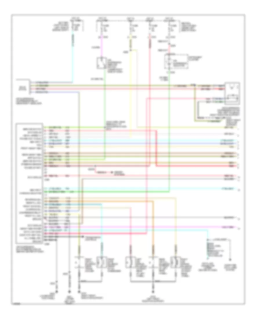
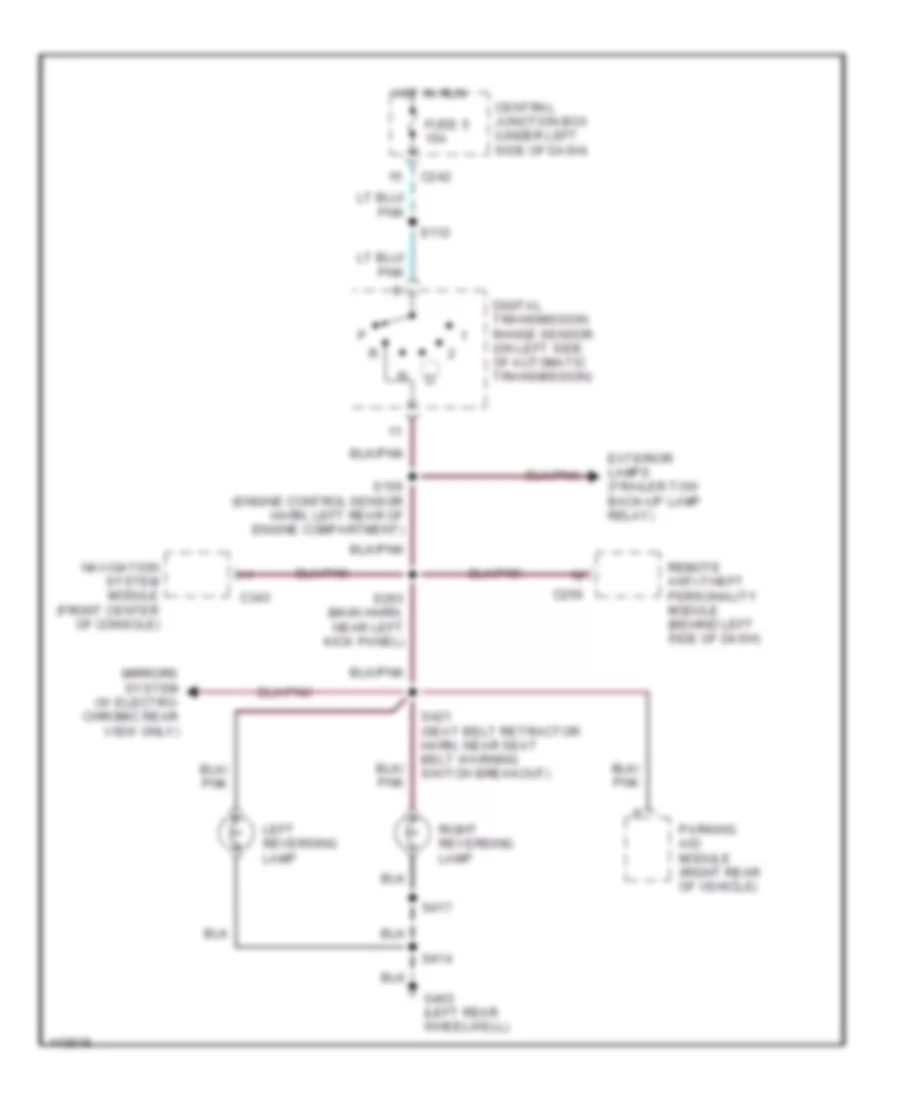
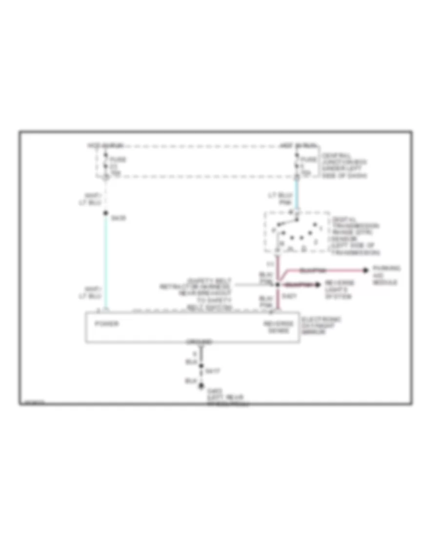
Back-up Lamps Wiring Diagram for Ford Expedition 2002
List of elements for Back-up Lamps Wiring Diagram for Ford Expedition 2002:
- C242
- C256
- C343
- Central junction box (under left side of dash)
- Digital transmission range sensor (on left side of automatic transmission)
- Exterior lamps (trailer tow back-up lamp relay)
- Fuse 5 15a
- G403 (left rear wheelwell)
- Hot in run
- Left reversing lamp
- Mirrors system (w electro- chromic rear view only)
- Navigation system module (front center of console)
- Parking aid module (right rear of vehicle)
- Remote anti-theft personality module (behind left side of dash)
- Right reversing lamp
- S112
- S150 (engine control sensor harn, left rear of engine compartment)
- S263 (main harn, near left kick panel)
- S414
- S417
- S421 (seat belt retractor harn, near seat belt warning switch breakout)
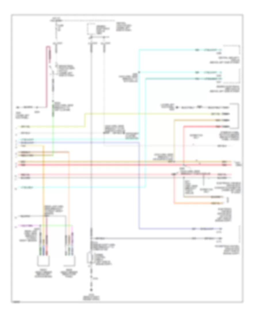
Exterior Lamps Wiring Diagram for Ford Expedition 2002
List of elements for Exterior Lamps Wiring Diagram for Ford Expedition 2002:
- (behind right side of dash) signal mirror relay block
- (engine ctrl sensor harn, near breakout to brake pressure switch) s115
- (main harn, near breakout to steering wheel rotation sensor) s261
- (main harn, near cooling fan brealkout) s260
- (main harn, near steering wheel rotation sensor breakout) s246
- (rear license lamp harn, near breakout to right license lamp) s416
- (seat belt harn, near breakout to torque on demand) s403
- Auto
- Autolamp module (behind center of dash)
- Battery junction box (on left side of engine compartment)
- Blower/ flasher relay block (behind center of dash)
- Brake pedal position switch (under left side of dash)
- C216
- C238
- C242
- C243
- Central junction box (under left side of dash)
- Flasher relay
- Fuse 10a
- Fuse 15a
- Fuse 20a
- Fuse 7.5a
- G103 (right front radiator support)
- G200 (lower right kick panel)
- G401 (left rear wheelwell)
- G403 (left rear wheelwell)
- Hazard
- Head
- High mount stop lamp 1
- High mount stop lamp 2
- High mount stop lamp 3
- Hot at all times
- Hot in run
- Instrument cluster
- Lamp harn, in breakout to hi mount stop lamp) s911
- Left
- Left exterior rear view mirror
- Left front park/ turn lamp
- Left license lamp
- Left mirror turn singal relay
- Left side lamp
- Left stop/ park/ turn lamp
- Left turn indicator
- Main light switch
- Multifunction switch
- Nca
- Normal
- Off
- Park
- Park lamp relay (w/ auto lamps)
- Pnk
- Right
- Right exterior rear view mirror
- Right front park/ turn lamp
- Right license lamp
- Right mirror turn signal relay
- Right side lamp
- Right stop/ park/ turn lamp
- Right turn indicator
- Rpo relay block 1 (behind right side of dash, above passenger air bag)
- S104
- S2001
- S202
- S204
- S220
- S224 (main harn, near breakout to instrument cluster)
- S228
- S231 (main harn, near breakout to instrument cluster)
- S245 (main harn, near breakout to rpo relay block 1)
- S247 (main harn, near steering wheel rotation sensor breakout)
- S251
- S414
- S415
- S417
- S501
- S600
- S909
- Trailer/ camper adapter circuit
Trailer/Camper Adapter Wiring Diagram for Ford Expedition 2002
List of elements for Trailer/Camper Adapter Wiring Diagram for Ford Expedition 2002:
- (battery feed)
- (battery)
- (electronic brake control)
- (electronic brakes)
- (engine cntrl sensor harn, left side of eng compt) s115
- (ground)
- (illumination feed)
- (left front radiator support) g104
- (left side of engine compt) battery junction box
- (left stop turn lamps)
- (main harn, left rear of eng compt) s260
- (main harn, near breakout to steering wheel rotation sensor) s261
- (right stop turn lamps)
- (trailer backup lamps)
- (trailer running lamps)
- Battery junction box (left side of engine compt)
- Brake pedal position switch (under left side of dash)
- Breakout to inst cluster)
- C242
- C243
- Central junction box (under left side of dash)
- Exterior lights (back-up lamps circuit)
- Exterior lights (exterior lights circuit)
- Fuse 10a
- Fuse 20a
- Fuse 30a
- G200 (lower right kick panel)
- G400 (left rear of vehicle)
- Head
- Hot at all times
- Hot in run
- Left turn signal output
- Main light switch
- Multi- function switch
- Off
- Park
- Red
- Right turn signal output
- S108
- S152
- S2001
- S201
- S224 (main harn, near breakout to instrument cluster)
- S228
- Trailer electronic brake control
- Trailer tow battery charge relay
- Trailer tow reversing lamp relay
- Trailer tow running lamp relay
- Trailer/ camper adapter
GROUND DISTRIBUTION
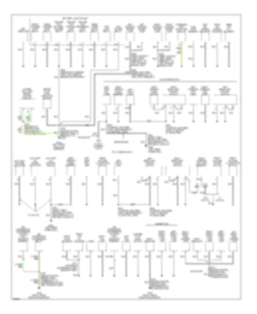
Ground Distribution Wiring Diagram (1 of 4) for Ford Expedition 2002
List of elements for Ground Distribution Wiring Diagram (1 of 4) for Ford Expedition 2002:
- (under center console) s366
- 4 wheel drive mode switch
- A/c clutch diode
- A/c compressor clutch solenoid
- Adjustable pedal switch
- Air bag sliding contact
- Air suspension/ evo steering module
- Ashtray illum- ination
- Autolamp module
- Auxiliary a/c relay
- Battery
- Battery junction box
- Blend door actuator
- Blower motor resistor
- Blower motor speed controller
- Blower relay
- Blower/flasher relay block
- Cd changer
- Cellular phone support electronics
- Clock
- Crankshaft position sensor shield
- Data link connector
- Daytime running lamps relay 1
- Daytime running lamps relay 2
- Daytime running lamps relay block
- Digital transmission range sensor
- Electronic automatic temperature control module
- Electronic variable orifice module
- Engine compartment lamp
- Flasher relay
- Function selector switch assembly
- G100 (right side of engine compt, near battery)
- G101 (right side of firewall)
- G102 (rear of right fender apron)
- G105 (right side of engine compt, near battery)
- G200 (lower right kick panel)
- G202 (upper left kick panel)
- G400 (left rear of vehicle)
- Glove compt lamp
- Harn, near breakout to console blower motor)
- Instrument cluster
- Main light switch
- Mass airflow sensor
- Powertrain control module
- Radio
- Rear integrated control panel
- Rear window defrost switch
- Rear wiper up relay
- Right rear of engine compt)
- Rpo relay block 2
- S102 (engine control sensor harn, near breakout to starter motor relay)
- S201 (main body harn, near breakout to air suspension/ evo steering module)
- S202 (main body harn, (near breakout to blower/ flasher relay box)
- S2020 (main harn, near breakout to belt minder module)
- S203 (main body harn, near breakout to rpo relay block)
- S204 (main body harn, near breakout to instrument cluster)
- Shift lock actuator
- Speed control servo
- Subwoofer amplifier
- Torque on demand relay
- Trailer tow
- Trailer tow ground
- Transfer case shift relays
- Video cassette player
- Video monitor
- W/ eatc
- W/ rear seat entertainment
- W/o eatc
- W/o memory
- Windshield wiper motor
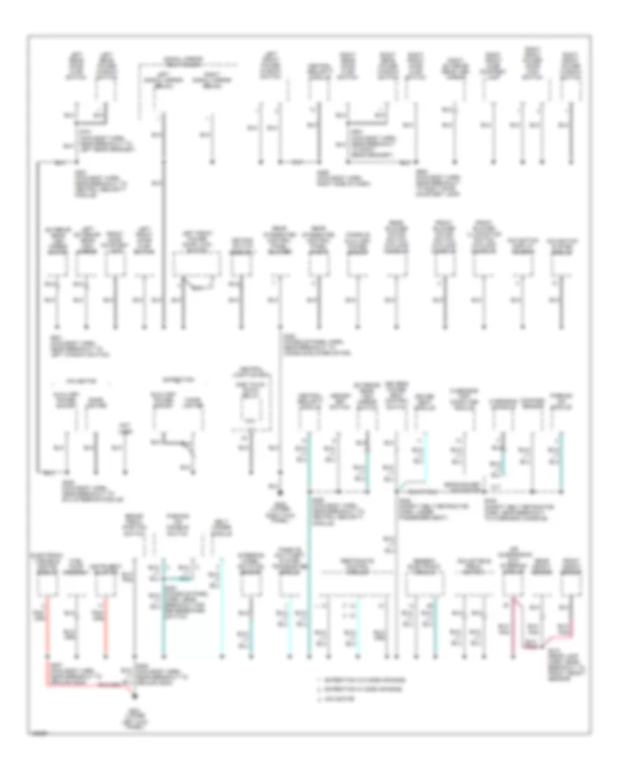
Ground Distribution Wiring Diagram (2 of 4) for Ford Expedition 2002
List of elements for Ground Distribution Wiring Diagram (2 of 4) for Ford Expedition 2002:
- 4 wheel anti-lock brake system module
- Air suspension compressor motor & vent solenoid assembly
- Air suspension compressor relay
- Auxiliary a/c blend actuator
- Auxiliary a/c control module
- Auxiliary a/c mode actuator
- Battery junction box
- Brake fluid level indicator switch
- Breakout to left running board lamp)
- Eddie bauer
- Expedition
- Fog lamp relay
- Front air fill solenoid
- Front blower illumination switch
- Front blower motor switch
- Front gate solenoid
- Front interior/ map lamp assembly
- Front washer pump relay
- Fuel pump assembly
- Full console only
- G103 (right front radiator support)
- G104 (left front radiator support)
- G402 (left rear wheelwell)
- Horn
- Left air spring solenoid
- Left fog lamp
- Left front park/ turn lamp
- Left front side marker lamp
- Left headlamp
- Left interior/ map lamp
- Left rear vent window switch
- Left running board lamp
- Left side rail lamp
- Left vanity lamp
- Mini console only
- Navigator
- Nca
- Overhead trip computer module
- Pcm power relay
- Rear air fill solenoid
- Rear blower illumination switch
- Rear washer pump relay
- Rear wiper down relay
- Right air spring solenoid
- Right fog lamp
- Right front park/ turn lamp
- Right front side marker lamp
- Right headlamp
- Right interior/ map lamp
- Right rear vent window switch
- Right running board lamp
- Roof opening panel assembly
- Roof opening panel switch
- Rpo relay block 2)
- S103 (engine control sensor harn, near breakout to ground g109)
- S106 (engine control sensor harn, in breakout to g108)
- S155 (engine control sensor harn, in breakout to compressor motor/ vent solenoid assy)
- S177 (air spring suspension harn, near battery)
- S400 (rear lamp harn, near breakout to fuel pump assembly)
- S424 (safety belt retractor harn, near breakout to rpo relay block 2)
- S913 (interior lamp feed harn, near breakout to left rail lamp)
- S923 (interior lamp feed harn, in center of headliner)
- Sensor harn, near breakout for 4wabs module)
- Sensor harn, near breakout to ground g109)
- To s414 (diagram 4 of 4)
- Trailer tow battery charge relay
- Trailer tow reversing lamp relay
- Trailer tow running lamp relay
- W/ aux a/c
- W/ vent
- W/o aux a/c
- W/o vent
- Washer fluid level switch
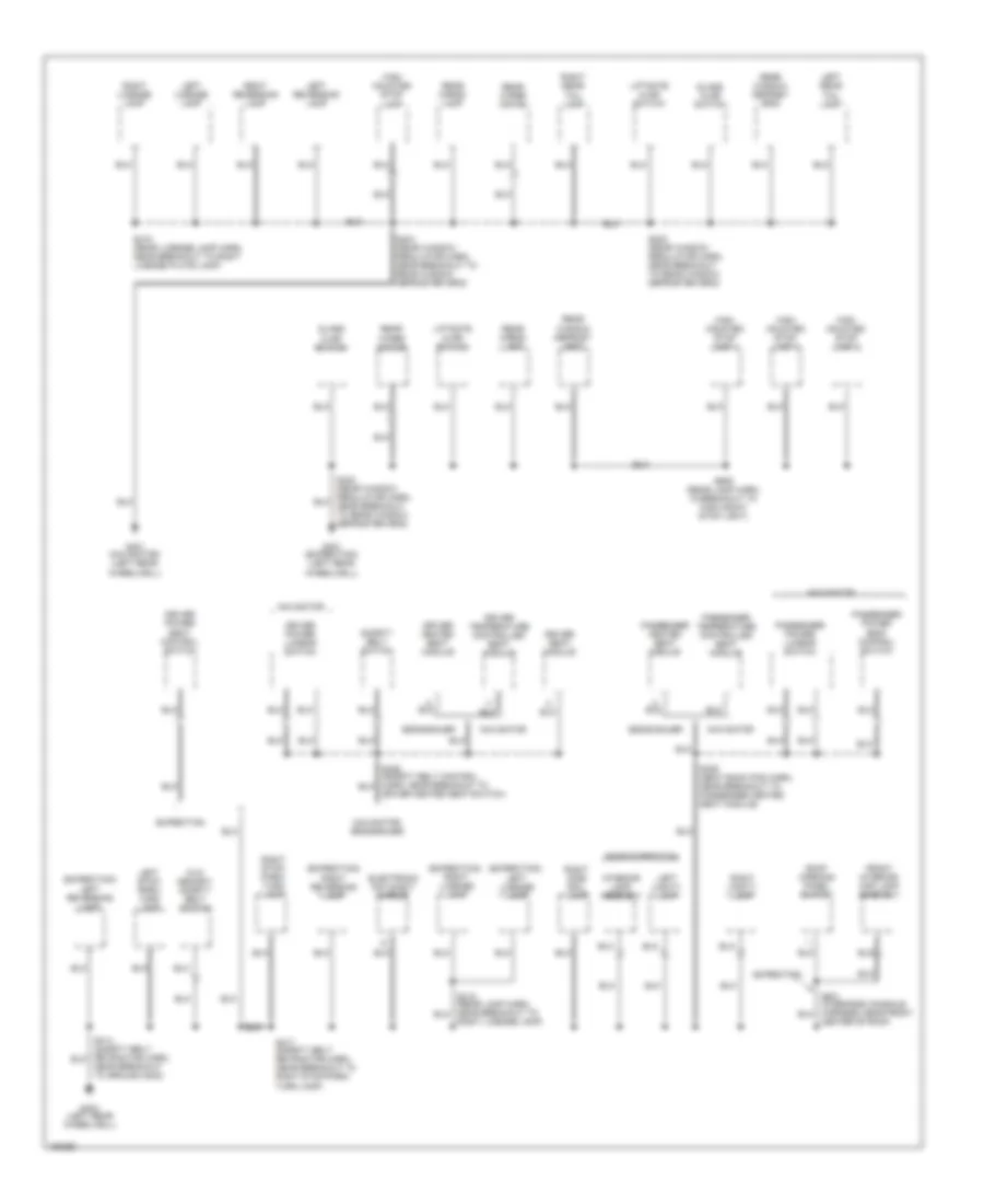
Ground Distribution Wiring Diagram (3 of 4) for Ford Expedition 2002
List of elements for Ground Distribution Wiring Diagram (3 of 4) for Ford Expedition 2002:
- 87a
- Adjustable pedal switch
- Air suspension/ evo steering module
- Auxiliary power socket
- Belt minder module
- Brake pedal position switch
- Central junction box
- Central security module
- Cigar lighter
- Compass sensor
- Console auxiliary power socket
- Driver seat module
- Driver's power seat control switch
- Eddie bauer/ navigator
- Electronic variable orifice module
- Expedition
- Expedition w/ side air bags
- Expedition w/o side air bags
- Exterior rear view mirror switch
- Front blower illumination switch (w/floor console)
- Front blower motor switch (w/floor console)
- Front door courtesy lamp
- Front height sensor
- Fuel pump assembly
- G200 (lower right kick panel)
- G201 (lower left kick panel)
- Generic electronic module
- Instrument cluster
- Keypad switch assembly
- Left exterior rear view mirror
- Left front door ajar switch
- Left front power door lock switch
- Left front power window switch
- Left rear door ajar switch
- Left rear power window switch
- Left signal mirror relay
- Memory set switch
- Navigation display housing
- Navigation system module
- Navigator
- Not used
- One touch down relay
- Overhead console
- Overhead trip computer module
- Parking aid disable switch
- Parking aid module
- Passive anti-theft system transceiver module
- Rear blower motor switch (w/floor console)
- Rear height sensor
- Rear integrated control panel (audio)
- Rear integrated control panel (blower)
- Restraints control module
- Right exterior rear view mirror
- Right front door ajar switch
- Right front door courtesy lamp
- Right front power door lock switch
- Right front power window switch
- Right rear door ajar switch
- Right rear power window switch
- Right signal mirror relay
- S205 (main body harn, near breakout to evo steering module)
- S207 (main body harn, near breakout to ground g202)
- S250 (main body harn, near breakout to central security module)
- S251 (main body harn, near breakout to central security module)
- S258 (main body harn, right side of dash)
- S308 (safety belt retractor harn, under passenger seat)
- S322 (console panel harn, near breakout to console blower motor)
- S410 (rear lamp harn, near breakout to front height sensor)
- S425 (safety belt retractor harn, near breakout to overhead console)
- S501 (main body harn, near breakout to left window switch)
- S600 (main body harn, near breakout to right door courtesy lamp)
- S701 (main body harn, near breakout to left rear grommet)
- Signal mirror relay block
- Steering wheel rotation sensor
- To right rear grommet)
- Xlt
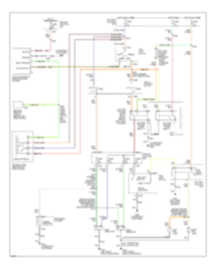
Ground Distribution Wiring Diagram (4 of 4) for Ford Expedition 2002
List of elements for Ground Distribution Wiring Diagram (4 of 4) for Ford Expedition 2002:
- (expedition) left license lamp
- (expedition) left reversing lamp
- (expedition) right license lamp
- (expedition) right reversing lamp
- (w/o memory) safety belt switch
- Base expedition
- Center of roof)
- Driver heated seat module
- Driver heated seat switch)
- Driver power lumbar switch
- Driver power seat control switch
- Driver seat module
- Driver temperature controlled seat module
- Eddie bauer
- Electronic day/night mirror
- Expedition
- Front interior/ map lamp assembly
- G401 (expedition) (left rear wheelwell)
- G401 (navigator) (left rear wheelwell)
- G403 (left rear wheelwell)
- Glass ajar switch
- High mounted stop lamp
- High mounted stop lamp 1
- High mounted stop lamp 2
- High mounted stop lamp 3
- Interior lamp assembly
- Left license lamp
- Left rear tail lamp
- Left reversing lamp
- Left stop/ park/ turn lamp
- Left vanity lamp
- Liftgate ajar switch
- Navigator
- Navigator/ eddie bauer
- Near breakout to ground g402)
- Passenger heated seat module
- Passenger power lumbar switch
- Passenger power seat control switch
- Passenger temperature controlled seat module
- Rear cargo lamp
- Rear window defrost grid
- Rear wiper motor
- Right license lamp
- Right license lamp)
- Right rear tail lamp
- Right reversing lamp
- Right side rail lamp
- Right stop/ park/ turn lamp
- Right vanity lamp
- Roof opening panel switch
- S329 (seat back pad harn, near breakout to passenger heated seat module)
- S402 (rear window regulator harn, near breakout to rear window defroster grid)
- S404 (rear window regulator harn, near breakout to rear window defroster grid)
- S415 (rear license lamp harn, near breakout to right license plate lamp)
- S417 (safety belt retractor harn, near breakout t0 right stop/park/ turn lamp)
- S909 (rear lamp harn, in breakout to high mount stop light)
- Safety belt switch
HEADLIGHTS
Autolamps & Fog Lamps Wiring Diagram, with DRL for Ford Expedition 2002
List of elements for Autolamps & Fog Lamps Wiring Diagram, with DRL for Ford Expedition 2002:
- (engine control sensor harness, near breakout at left front radiator support) s114
- (engine control sensor harness, near breakout to left fog lamp) s147
- (expedition) (navigator)
- (lower right kick panel) g200
- (main harness, near breakout to central junction box) s2000
- Auto
- Autolamp module (behind center of dash)
- Autolamp out
- Battery junction box
- C238
- C242
- C243
- C246
- C257
- C259
- Central junction box
- Central security module (behind left side of dash)
- Daytime running lamps relay 1
- Daytime running lamps relay 2
- Daytime running lamps relay block (behind right side of dash)
- Daytime running lamps resistor (in left front of engine compt)
- Fog lamp relay
- Fog lamp switch
- Fog on indicator
- Fuse 10a
- Fuse 15a
- Fuse 20a
- Fuse 30a
- Fuse 5a
- G103 (right front radiator support)
- G104 (left front radiator support)
- G200 (lower right kick panel)
- Ground
- Head
- Headlamp relay
- Hi-beam indicator
- Hot at all times
- Hot in run
- Hot in start or run
- Ignition
- Instrument cluster
- Left fog lamp
- Left headlamp
- Left side of dash)
- Main light switch
- Multi- function switch
- Off
- Park
- Pass
- Relay ground
- Right fog lamp
- Right headlamp
- Rpo relay box (behind right side of dash)
- S109
- S152
- S203
- S204
- S212
- S222
- S225
- S245 (main harn, near break- out to rpo relay block)
Autolamps & Fog Lamps Wiring Diagram, without DRL for Ford Expedition 2002
List of elements for Autolamps & Fog Lamps Wiring Diagram, without DRL for Ford Expedition 2002:
- (engine control sensor harness, near breakout at left front radiator support) s114
- (engine control sensor harness, near breakout to left fog lamp) s147
- (expedition) (navigator)
- (lower right kick panel) g200
- (main harness, near breakout to central junction box) s2000
- Auto
- Autolamp module (behind center of dash)
- Autolamp out
- Battery junction box
- C238
- C242
- C243
- C246
- C257
- C259
- Central junction box
- Central security module (behind left side of dash)
- Fog lamp relay
- Fog lamp switch
- Fog on indicator
- Fuse 10a
- Fuse 15a
- Fuse 20a
- Fuse 30a
- Fuse 5a
- G103 (right front radiator support)
- G104 (left front radiator support)
- G200 (lower right kick panel)
- Ground
- Head
- Headlamp relay
- Hi-beam indicator
- Hot at all times
- Hot in start or run
- Ignition
- Instrument cluster
- Left fog lamp
- Left headlamp
- Main light switch
- Multi- function switch
- Off
- Park
- Pass
- Relay ground
- Right fog lamp
- Right headlamp
- Rpo relay box (behind right side of dash)
- S106
- S152
- S203
- S204
- S212
- S225
- S245 (main harn, near break- out to rpo relay block)
Headlamps & Fog Lamps Wiring Diagram, with DRL for Ford Expedition 2002
List of elements for Headlamps & Fog Lamps Wiring Diagram, with DRL for Ford Expedition 2002:
- (engine control sensor harn, near breakout to left fog lamp) s147
- (expedition) (navigator)
- (lower right kick panel) g200
- Battery junction box
- C238
- C242
- C243
- C246
- C259
- Central junction box
- Daytime running lamps relay 1
- Daytime running lamps relay 2
- Daytime running lamps relay block (behind right side of dash)
- Daytime running lamps resistor (in left front of engine compt)
- Fog lamp relay
- Fog lamp switch
- Fog on indicator
- Fuse 10a
- Fuse 15a
- Fuse 20a
- Fuse 30a
- Fuse 5a
- G103 (right front radiator support)
- G104 (left front radiator support)
- G200 (lower right kick panel)
- Head
- Hi-beam indicator
- Hot at all times
- Hot in run
- Instrument cluster
- Left fog lamp
- Left headlamp
- Left side of dash)
- Main light
- Main light switch
- Multi- function switch
- Off
- Park
- Pass
- Right fog lamp
- Right headlamp
- S109
- S152
- S2000 (main harness, near breakout to central junction box)
- S203
- S204
- S212
- S222
- Switch
Headlamps & Fog Lamps Wiring Diagram, without DRL for Ford Expedition 2002
List of elements for Headlamps & Fog Lamps Wiring Diagram, without DRL for Ford Expedition 2002:
- (engine control sensor harness, near breakout at left front radiator support) s114
- (expedition) (navigator)
- Battery junction box
- C238
- C242
- C243
- C246
- C259
- Central junction box
- Fog lamp relay
- Fog lamp switch
- Fog on indicator
- Fuse 10a
- Fuse 15a
- Fuse 20a
- Fuse 30a
- Fuse 5a
- G103 (right front radiator support)
- G104 (left front radiator support)
- G200 (lower right kick panel)
- Head
- Hi-beam indicator
- Hot at all times
- Instrument cluster
- Left fog lamp
- Left headlamp
- Main light
- Main light switch
- Multi- function switch
- Off
- Park
- Pass
- Right fog lamp
- Right headlamp
- S147 (engine control sensor harness, near breakout to left fog lamp)
- S152
- S2000 (main harness, near breakout to central junction box)
- S204
- S212
- Switch
HORN
Horn Wiring Diagram for Ford Expedition 2002
List of elements for Horn Wiring Diagram for Ford Expedition 2002:
- 20a
- Air bag sliding contact
- Battery junction box (left side of engine compartment)
- C256
- Central securiy module (behind left side of dash)
- Climate control system
- Fuse 7
- G103 (right front radiator support)
- Horn (right front of engine compt)
- Horn switch
- Hot at all times
- Nca
- S104
- Speed control servo (left side of engine compt)
- Steering column assembly
INSTRUMENT CLUSTER
Instrument Cluster Wiring Diagram for Ford Expedition 2002
List of elements for Instrument Cluster Wiring Diagram for Ford Expedition 2002:
- (conn a)
- (conn b)
- (lower right kick panel)
- (lower right kick panel) g200
- 4 wheel anti- lock brake system module (on left side of engine compt)
- 4x4 high ind
- 4x4 low ind
- 820 ohms
- A10
- A14
- A15
- A17
- A22
- Air suspension/ evo steering module (behind center of dash)
- Airbag ind
- Anti-lock brakes system
- Anti-lock ind
- B10
- B11
- B12
- B13
- B14
- B16
- B17
- B18
- B19
- B20
- Belt minder module (behind center of dash)
- Bias ckt
- Brake fluid level indicator switch (on brake fluid reservoir)
- Brake ind
- C146
- C2005
- C2012
- C237
- C238
- C239
- C240
- C241
- C242
- C243
- C296
- Central junction box
- Charge ind
- Check suspension ind
- Clock
- Computer data lines system
- Cruise control ind
- Door ajar ind
- Engine oil pressure switch (on left front of engine, next to p/s pump)
- Exterior lights system
- Fasten safety belt ind
- Fuel pump assembly (under vehicle, at fuel tank)
- Fuel pump module
- Fuse 30a
- Fuse 5a
- G104 (left front radiator support)
- G200
- G201 (lower left kick panel)
- Generic electronic module (behind left side of dash)
- Headlights system
- Hi beam ind
- Hot at all times
- Hot in accy or run
- Hot in park or head
- Hot in run
- Hot in start or run
- Illumination
- Instrument cluster
- Interior lights system
- Left turn ind
- Low fuel ind
- Low oil/high coolant ind
- Low washer fluid ind
- Malfunction indicator
- Micro- processor
- Microprocessor
- Nca
- Near breakout to 4wabs module)
- Overhead trip computer module (in front of overhead console)
- Parking brake switch (on right side of park brake lever)
- Passive anti-theft system transceiver module (behind center of dash)
- Restraints control module (behind right side of dash)
- Right turn ind
- Rx input
- S106
- S2002
- S2021 (main harn, near belt minder module)
- S203
- S204
- S207
- S211
- S223
- S265
- S289
- S298 (main harn, near breakout to insrument cluster)
- Shift interlock system
- Speed control servo (left side of eng compt)
- Starting/charging system
- Theft indicator micro cluster
- Tx input
Overhead Console Wiring Diagram for Ford Expedition 2002
List of elements for Overhead Console Wiring Diagram for Ford Expedition 2002:
- Ambient temperature sensor (left front of engine compt)
- C243
- Central junction box
- Compass
- Electronic suspension system
- Fuse 10a
- G201 (lower left kick panel)
- Hot in run
- Overhead console
- Power distribution system
- S425
- S435
- Thermometer
Trip Computer Wiring Diagram for Ford Expedition 2002
List of elements for Trip Computer Wiring Diagram for Ford Expedition 2002:
- (lower left kick panel) g201
- Air suspension/ evo steering module (behind center of dash)
- Awd low
- Batt sav lmp
- C237
- C242
- Central junction box
- Compass +
- Compass -
- Compass sensor (in overhead console)
- Data out
- Electronic suspension system
- Fuel pump assembly
- Fuel sender
- Fuse 5a
- G104 (left front
- G402 (left rear wheelwell)
- Ground
- Hot at all times
- Hot in run
- Instrument cluster
- Interior lights system
- Left interior/ map lamp
- Left map lt
- Main light
- Near breakout to instrument cluster)
- Overhead trip computer module (in front of overhead console)
- Pnk
- Power
- Powertrain control module (on right side of engine compt)
- Radiator support)
- Right interior/ map lamp
- Right map lt
- S267 (main harn, near breakout to evo module)
- S289
- S400
- S425
- S426
- S923
- Speed sens
- Transmissions system (all wheel drive)
INTERIOR LIGHTS
Courtesy Lamps Wiring Diagram for Ford Expedition 2002
List of elements for Courtesy Lamps Wiring Diagram for Ford Expedition 2002:
- g102 (rear of right fender apron)
- (body main harn, behind right side of dash) s239
- (expedition) (left rear wheelwell) g402
- (int lp feed harn, near left side rail lamp breakout)
- (navigator)
- (near fuel tank) g403
- (rear lamp extension harn, near right side running board) s434
- (seat belt ret harn, near torque on demand breakout)
- Battery junction box
- Battery saver input
- Battery saver relay
- C242
- C243
- C245
- C267
- C928
- Central junction box
- Door
- Engine compartment lamp
- Front interior/ map lamp assembly
- Fuse 10a
- Fuse 15a
- G104 (left front radiator support)
- G200 (lower right kick panel)
- G401 (left rear wheelwell)
- G402 (left rear wheelwell) (expedition)
- G403 (near fuel tank) (navigator)
- Generic electronic module (gem)
- Glove compartment lamp
- Hot at all times
- Int lamp
- Interior lamp assembly
- Interior lamp relay
- Interior lamp relay input
- Interior lamp switch
- Left front door courtesy lamp
- Left interior/ map lamp
- Left map lamp switch
- Left running board lamp
- Left side rail lamp
- Left vanity lamp
- Main light switch
- Map lamps
- Nca
- Off
- Off
- Overhead
- Overhead trip computer module (w/ mini console)
- Pnk
- Rear cargo lamp
- Right front door courtesy lamp
- Right interior/ map lamp
- Right map lamp switch
- Right running board lamp
- Right side rail lamp
- Right vanity lamp
- S102
- S164 (eng cntrl sens harn, left rear of eng compt)
- S200
- S203
- S204
- S240 (main harn, near ashtray illum breakout)
- S251
- S400
- S404
- S408 (rear lamp harn, in left side running board)
- S417
- S419
- S420 (seat belt ret harn, near right kick panel)
- S428
- S429
- S430 (rear lamp extension harn, in left side running board)
- S501
- S600
- S912 (int lp feed harn, near left rear wheelwell)
- S913
- S917
- S923
- S931
- Universal garage door opener
- W/ aux a/c
- W/ full overhead console
- W/ mini console only
- W/ mini console or full over head console only
- W/o aux a/c w/ full overhead console, or w/o full overhead console
- W/o full overhead console
- W/o full w/ full overhead console console
- Wiper/ washer system
- Xlt only
Instrument Illumination Wiring Diagram for Ford Expedition 2002
List of elements for Instrument Illumination Wiring Diagram for Ford Expedition 2002:
- (center of headliner) s924
- (left rear wheelwell) g402
- (lower right kick panel) g200
- (main harn, behind left side of dash) s242
- (navigator)
- (near blower motor breakout) s350
- 4 wheel drive mode switch
- Adjust- able pedal switch
- Airbag slidilng contact
- Airbag sliding contact
- Ashtray illumination
- Audio/ climate cntrl sw
- Back- light
- Battery junction box
- C219
- C237
- C238
- C242
- C243
- C245
- C246
- C262
- C280
- C281
- C283
- C314
- C342
- C347
- C384
- C390
- C508
- C510
- C608
- C609
- C709
- C809
- C915
- C924
- C928
- C929
- C930
- C931
- C955
- Central junction box
- Cigar lighter
- Clock
- Dimmer module
- Electronic automatic temperature control module
- Expedition
- Exterior lights circuit
- Front blower illumi- nation switch
- Front blower illumination switch
- Full overhead console or xlt
- Function selector switch assembly
- Fuse 5a
- Fuse 6 15a
- G200 (lower right kick panel)
- G201 (lower left kick panel)
- G402 (left rear wheelwell)
- Gnd
- Head
- Hot at all times
- Instrument cluster (6 bulbs)
- Left front power door lock switch
- Left front power window switch
- Left rear power window switch
- Left rear vent window switch
- Main light switch
- Mini overhead console
- Nav- igation display housing (nav- igator)
- Navigation system module
- Navigator
- Nca
- Off
- Overhead console
- Overhead trip computer module
- Park
- Parking aid disable switch
- Radio
- Rear blower illumi- nation switch
- Rear blower illumination switch
- Rear inte- grated control panel
- Rear window defrost switch
- Right front power door lock switch
- Right front power window switch
- Right rear power window switch
- Right rear vent window switch
- Roof opening panel switch
- S201
- S2013
- S202
- S203
- S204
- S205
- S211 (main harn, behind left side of dash)
- S224 (main harn, near near instrument cluster breakout)
- S251
- S253 (body main harn, behind right side of dash)
- S256 (body main harn, near lock relay box breakout)
- S258
- S286 (main harn, near breakout to relay block)
- S322
- S351
- S411 (near safety belt switch breakout)
- S501
- S600
- S701
- S801
- S913
- S915 (near rear blower switch breakout)
- S923
- S931
- S932 (center of headliner)
- Speed cntrl sw
- Speed control servo (left side of engine compt)
- Steering column assembly
- W/full overhead console w/o aux a/c
- Xlt only
MEMORY SYSTEMS
Adjustable Pedal Wiring Diagram for Ford Expedition 2002
List of elements for Adjustable Pedal Wiring Diagram for Ford Expedition 2002:
- Adjustable pedal motor
- Adjustable pedal switch
- C2000
- C2001
- C242
- C351
- C357
- Central junction box (under left side of dash)
- Driver seat module (under driver seat)
- Fuse 4 7.5a
- G200 (lower right kick panel)
- G201 (lower left kick panel)
- Hot at all times
- Interior lights system
- Nca
- S204
- S208
- S219
- S308 (safety belt retractor harn, under passenger seat)
- S309 (safety belt retractor harn, under passenger seat)
Driver's Memory Seat Wiring Diagram for Ford Expedition 2002
List of elements for Driver's Memory Seat Wiring Diagram for Ford Expedition 2002:
- (left rear wheelwell) g403
- (lower left inner kick panel) g201
- (lower left kick panel) g201
- (main body harn, near breakout to central security module)
- (main body harness, near breakout to in-line connector, behind right side of dash)
- (safety belt retractor harn, behind left side of instrument panel)
- (safety belt retractor harn, under passenger seat)
- Adj. brake pedal circuit
- Adjustable pedal motor
- Battery junction box (on left side of engine compartment)
- C2001
- C242
- C243
- C257
- C302
- C303
- C307
- C315
- C316
- C319
- C351
- C356
- C357
- C358
- C359
- Central junction box (under left side of dash)
- Data link connector (dlc) (under center of dash)
- Dlc
- Driver power lumber switch
- Driver power motor seat assembly
- Driver power seat control switch
- Driver seat module (under driver seat)
- Entire seat
- Front height motor
- Front of seat
- Fuse 30a
- Fuse 5a
- Fuse 7.5a
- Fwd
- Fwd/rwd motor
- G201 (lower left inner kick panel)
- Gnd
- Ground
- Hot at all times
- Hot in start
- Lefft horiz motor
- Left front motor
- Left horiz motor
- Left mirr up/dn mtr gnd
- Left mirr up/dn pos sens
- Left mirror l/r mtr
- Left mirror l/r mtr gnd
- Left mirror posit sensor
- Left rear motor
- Mem 1
- Mem 2
- Memory seat sw lamp dr
- Memory seat sw posit 1
- Memory seat sw posit 2
- Memory seat sw set
- Memory set switch
- Mirr posit sens gnd
- Mirr posit sensor feed
- Mirr sw horiz left
- Mirr sw horiz right
- Mirr sw vert left
- Mirr sw vert right
- Mirror sw common
- Nca
- Pedal backward
- Pedal forward
- Pedal sensor
- Power
- Power mirrors system
- Rear height motor
- Rear of seat
- Red
- Remote anti-theft personality (rap) module (behind left side of dash)
- Right mirr l/r posit sens
- Right mirr up/dn mtr gnd
- Right mirr up/dn posit
- Right mirror l/r mtr
- Right mirror l/r mtr gnd
- Right mirror up/dn mtr
- Rwd
- S2009
- S219
- S220
- S236
- S248
- S250
- S308
- S309
- S310
- S326
- S332
- Seat posit sensor front
- Seat posit sensor horiz
- Seat posit sensor rear
- Seat position sensor (+)
- Seat position sensor (-)
- Set
Memory Mirrors Wiring Diagram for Ford Expedition 2002
List of elements for Memory Mirrors Wiring Diagram for Ford Expedition 2002:
- (safety belt retractor harn, behind left side of instrument panel)
- C242
- C356
- C357
- C507
- C607
- Central junction box (under left side of dash)
- Data link connector (dlc) (under center of dash)
- Defogger system
- Direct- tional switch
- Dlc
- Driver seat module (under driver's seat)
- Exterior rear view mirror switch
- Exterior lights system
- Fuse 7.5a
- G201 (lower left kick panel)
- Horiz
- Horiz mtr
- Hot at all times
- Left exterior rear view mirror
- Left heated mirror
- Left mirr up/dn mtr gnd
- Left mirr up/dn pos sens
- Left mirror l/r mtr
- Left mirror l/r mtr gnd
- Left mirror posit sensor
- Left/right mirror select switch
- Mirr posit sens gnd
- Mirr posit sensor feed
- Mirr sw horiz left
- Mirr sw horiz right
- Mirr sw vert left
- Mirr sw vert right
- Mirror sw common
- Nca
- Pnk
- Red
- Right exterior rear view mirror
- Right heated mirror
- Right mirr l/r posit sens
- Right mirr up/dn mtr gnd
- Right mirr up/dn posit
- Right mirror l/r mtr
- Right mirror l/r mtr gnd
- Right mirror up/dn mtr
- S220
- S237 (main body harness, near breakout to in-line connector behind right side of dash)
- S243 (main body harness, near breakout to in-line connector behind right side of dash)
- S250
- S332
- Vert
- Vert mtr
NAVIGATION
Navigation Wiring Diagram for Ford Expedition 2002
List of elements for Navigation Wiring Diagram for Ford Expedition 2002:
- (console panel harness, near front center of floor console)
- (console panel wiring harness, near b/o to cd changer)
- Antenna
- C242
- C243
- C300
- C343
- C344
- C345
- C346
- C347
- C348
- Central junction box (under left side of dash)
- Converted speed
- D2b (+) database
- D2b (-) database
- Display gnd
- Display ground
- Display on/off
- Fuse 18 5a
- Fuse 2 5a
- Fuse 8 5a
- G200 (behind right kick panel)
- Generic electronic module
- Ground
- Hot at all times
- Hot in acc or run
- Hot in park or head
- Instrument illumination
- Navigation display housing (center of dash)
- Navigation system module (behind center of dash)
- Nca
- Power
- Pwm dimming
- Reverse lights
- S267
- S289
- S322
- S341
- S353
- S354
- Speaker (+)
- Speaker (-)
- Transmission input (rev)
- Video green/csync
- Video red
- Video red gnd
- Video shield
- Vss
Parking Assistant Wiring Diagram for Ford Expedition 2002
List of elements for Parking Assistant Wiring Diagram for Ford Expedition 2002:
- (back-up alarm harness, near b/0 to left inner sensor)
- (behind left kick panel)
- (safety belt retractor harness, near front of left rear wheelwell)
- 12v in reverse
- Battery junction box
- C182
- C256
- C342
- C343
- C406
- C407
- C460
- C461
- C470
- C471
- C904
- Central junction box
- Data link connector (under center of dash)
- Digital trans range sensor module (raps) (on trans)
- Driver seat module
- Electronic day/night mirror
- Fuse 6 5a
- G201
- Ground
- Hot in run
- Instrument illumination
- Iso 9141
- Left center parking aid sensor
- Left center sensor input
- Left outer parking aid sensor
- Left outer sensor input
- Left reversing lamp
- Navigation system module (behind center of dash)
- On/off switch
- Parking aid disable switch (in glove box)
- Parking aid module (right rear of vehicle)
- Parking aid speaker
- Power
- Remote anti- theft personality module (raps) (left rear quarter panel)
- Reverse input
- Right center parking aid sensor
- Right center sensor input
- Right outer parking aid sensor
- Right outer sensor input
- Right reversing lamp
- S150 (eng sensor harness, near c160)
- S229 (main harness, near breakout to instrument cluster)
- S263 (main harness, near b/o to g200)
- S265
- S332 (safety belt retractor harness, near b/o to c208 in-line)
- S351
- S421 (safety belt retractor harness, near b/o to safety belt switch)
- S425
- S440
- S445
- Sensor ground
- Sensor power
- Speaker (+)
- Speaker (-)
- Status led
- To multiplex communication network
- W/memory seat
POWER DISTRIBUTION
Power Distribution Wiring Diagram (1 of 4) for Ford Expedition 2002
List of elements for Power Distribution Wiring Diagram (1 of 4) for Ford Expedition 2002:
- (cable assembly harness, near battery) red s1001
- (console panel harn, near console blower motor) s305
- (eng harn, near 4wabs module) s107
- (engine harn, in breakout to battery junction box) s108
- (engine harn, left side of eng compt)
- (main harn, near breakout to steering wheel rotation sensor) s212
- (main harn, near main light switch) s2013
- (main harn, near radio)
- (seatbelt harn, near passenger lumbar switch)
- 4 wheel anti-lock brake system 4wabs module
- Air suspension compressor relay
- Auxiliary a/c relay
- Auxiliary power socket
- Battery
- Battery junction box
- Battery junction box (left side of engine compartment)
- C243
- C256
- C257
- Cd changer
- Cellular telephone support electronics
- Central junction box (under left side of dash)
- Central security module
- Console auxiliary power socket
- Daytime running lamps resistor
- Fog lamp relay
- From a fuse 8 (diagram 1 of 4)
- Fuse 10a
- Fuse 15a
- Fuse 20a
- Fuse 25a
- Fuse 30a
- Fuse 50a
- Generator
- Headlamp relay
- Main light switch
- Multi- function switch
- Nca
- Passenger power lumbar switch
- Passenger power seat control switch
- Radio
- Rear integrated control panel
- Rear wiper down relay
- Rear wiper up relay
- Red
- Rpo relay block 1
- Rpo relay block 2
- S1002 (cable assembly harness, near battery)
- S109
- S2012
- S311
- Starter motor
- Starter motor relay
- Subwoofer amplifier
- To fuse (diagram 2 of 4)
- To fuse 103 (diagram 1 of 4)
- To fuse 2 (diagram 3 of 4)
- Trailer tow back-up lamp relay
- Trailer tow battery charge relay
- Trailer tow running lamp relay
- Wot relay
Power Distribution Wiring Diagram (2 of 4) for Ford Expedition 2002
List of elements for Power Distribution Wiring Diagram (2 of 4) for Ford Expedition 2002:
- (console panel harn, near cd changer)
- (diagram 3 of 4)
- (engine compt harn, left rear of engine compt) s113
- (main harn, in breakout to central junction box) s265
- (main harn, in breakout to transfer case) s213
- (main harn, left rear of engine compt)
- (main harn, near blower motor speed controller) s2014
- (main harn, near breakout to instrument cluster) s222
- (main harn, near breakout to instrument cluster) s223
- (seatbelt harn, near driver power seat motor) s310
- Acc
- Acc delay relay
- Adjustable pedal switch
- Air suspension evo steering module
- Battery junction box
- Battery junction box (left side of engine compt)
- Blend door actuator
- Blower relay
- Blower/ flasher relay block
- C238
- C242
- C243
- C256
- C262
- C267
- C295
- Cellular phone support electronics
- Central junction box
- Central junction box (under left side of dash)
- Circuit breaker 30a
- Clock
- Compass sensor
- Daytime running lights 1 relay
- Daytime running lights relay block
- Digital transmission range (dtr) sensor
- Driver heated seat module
- Driver power lumbar switch
- Driver power seat control switch
- Driver seat module
- Driver temperature controlled seat module
- Electronic variable orifice module
- From b fuse 101 (diagram 1 of 4)
- Front washer pump relay
- Fuel pump relay
- Function selector switch assembly
- Fuse 15a
- Fuse 20a
- Fuse 30a
- Fuse 40a
- Fuse 5a
- Generic electronic module
- Heated grid relay
- Ignition switch
- Instrument cluster
- Lock
- Navigation system module
- Navigator/eddie bauer
- Nca
- Off
- Overhead trip computer module
- Parking aid module (pam)
- Parking brake release switch
- Passenger heated seat module
- Passenger temperature controlled seat module
- Pcm power relay
- Radio
- Rear washer pump relay
- Red
- Remote anti-theft personality module
- Run
- S112 (eng harn, left rear of engine compt)
- S2021 main harn, near breakout to belt minder module)
- S214 (main harn, near steering wheel rotation sensor)
- S215 (main harn, in breakout to ignition switch)
- S221
- S297
- S353
- S365 (in center console)
- S426 (seatbelt harn, over- head console)
- Shift lock actuator
- Speed control servo
- Start
- Steering wheel rotation sensor
- To fuse 20
- To fuse 22 (diagram 4 of 4)
- To fuse 29 (diagram 3 of 4)
- Torque on-demand relay
- Trailer tow (battery feed)
- Transfer case shift relays
- Video cassette player
- Video monitor
- W/ memory
- W/climate control
- W/o climate control
- W/o memory
- Windshield wiper motor
- Wiper hi/lo relay
- Wiper run/park relay
Power Distribution Wiring Diagram (3 of 4) for Ford Expedition 2002
List of elements for Power Distribution Wiring Diagram (3 of 4) for Ford Expedition 2002:
- (body harn, near breakout to park brake switch) s220
- (console panel harn, near break- out to cd changer)
- (fuel charge harn, in breakout to fuel injector 3) s161
- (fuel charge harn, in breakout to fuel injector 7) s162
- (main harn, near breakout to instrument cluster)
- (main harn, near breakout to instrument cluster) s289
- (seatbelt retractor harn, near breakout to transfer case) s307
- Adjustable pedal switch
- Air suspension service switch
- Air suspension/ evo steering module
- Autolamp module
- Battery junction box
- Battery saver relay
- Belt minder module
- C238
- C242
- C243
- C256
- C257
- C267
- C268
- C295
- C356
- Central junction box (under left side of dash)
- Central security module
- Clock
- Coil on plug 1
- Coil on plug 2
- Coil on plug 3
- Coil on plug 4
- Coil on plug 5
- Coil on plug 6
- Coil on plug 7
- Coil on plug 8
- Digital transmission range sensor
- Driver power seat control switch
- Driver seat module
- Electronic automatic temperature control module
- Exterior rear view mirror switch
- From fuse 1 (diagram 1 of 4)
- From fuse 21 (diagram 2 of 4)
- From ignition switch (diagram 2 of 4)
- Fuse 15a
- Fuse 30a
- Fuse 5a
- Fuse 7.5a
- Generic electronic module
- Instrument cluster
- Interior lamp relay
- Memory set switch
- Navigation display housing
- Navigation system module
- Nca
- Overhead trip computer module
- Passive anti-theft system control module
- Pcm power diode
- Pcm power relay
- Powertrain control module
- Radio
- Radio noise capacitor 1
- Radio noise capacitor 2
- S116 (engine harn, left rear of engine compt)
- S117 (fuel charge harn, right rear of engine compt)
- S2002 (main harn, near breakout to central junction box)
- S2009 (main body harn, near breakout to instrument cluster)
- S219 (main harn, near breakout to evo module)
- S225
- S354
- To fuse 3 (diagram 4 of 4)
- Transmission control switch
Power Distribution Wiring Diagram (4 of 4) for Ford Expedition 2002
List of elements for Power Distribution Wiring Diagram (4 of 4) for Ford Expedition 2002:
- (front seat- back pad harness, near passenger heated seat switch)
- (main harn, in breakout to central junction box) s228
- (main harn, near breakout to 4wd mode switch) s2005
- (main harn, near breakout to central junction box) s2001
- (main harn, near breakout to eatc module) s292
- (seatbelt harn, near breakout to aux a/c mode switch) s422
- (seatbelt harn, near breakout to right park/ stop/turn lamp)
- 4 wheel anti-lock brake system (4wabs) module
- Auxiliary a/c blend actautor
- Auxiliary a/c control module
- Auxiliary a/c mode actuator
- Auxiliary a/c relay
- Battery junction box
- Blower relay
- Blower/ flasher relay block
- Brake pedal position switch
- Brake pressure switch
- C242
- C243
- C267
- C280
- C436
- Central junction box (under left side of dash)
- Cigar lighter
- Console blower relay
- Data link connector
- Driver heated seat module
- Driver heated seat switch
- Driver temperature controlled seat module
- Electronic automatic temperature control module
- Electronic day/ night mirror
- Expedition
- Flasher relay
- From fuse 4 (diagram 3 of 4)
- From ignition switch (diagram 2 of 4)
- Function selector switch assembly
- Fuse 10a
- Fuse 20a
- Fuse 5a
- G200 (right kick panel)
- Generic electronic module
- Interior lights system
- Navigator
- Nca
- Overhead console
- Passenger heated seat module
- Passenger heated seat switch
- Passenger temperature controlled seat module
- Rear integrated control panel
- Restraints control module (rcm)
- Rpo relay block 1
- Rpo relay block 2
- S205
- S296
- S325 (seatbelt harn, near driver heated seat switch)
- S328
- S435
- Tan/red
- Torque on-demand (tod) relay
- Trailer tow battery charge relay
- W/climate controlled seats
- W/eatc
- W/heated seats
- W/o eatc
POWER DOOR LOCKS
Power Door Lock Wiring Diagram for Ford Expedition 2002
List of elements for Power Door Lock Wiring Diagram for Ford Expedition 2002:
- (body harn, near breakout to remote anti-theft personality module) s235
- (body harn, near breakout to right door courtesy lamp) s604
- (body main harn, near parking brake switch breakout) s603
- (body main harn, near right door courtesy lamp breakout) s504
- All lock
- All unlock
- Battery
- Battery junction box (left side of engine compt)
- C256
- C257
- Central security module (behind left side of dash)
- Drvr lock
- Fuse 15a
- Fuse 20a
- Fuse 30a
- G200 (lower right kick panel)
- G201 (lower left kick panel)
- Ground
- Hot at all times
- Interior lights system
- Left front door lock actuator
- Left front power door lock switch
- Left rear door lock actuator
- Liftgate door lock actuator
- Lock
- Lock in
- Right front door lock actuator
- Right front power door lock switch
- Right rear door lock actuator
- S2013
- S234 (body harn, near breakout to remote anti-theft personality module)
- S250
- S251
- S258
- S501
- S600
- Unlock
- Unlock in
POWER MIRRORS
Electronic Day/Night Mirror Wiring Diagram for Ford Expedition 2002
List of elements for Electronic Day/Night Mirror Wiring Diagram for Ford Expedition 2002:
- (safety belt retractor harness, near breakout to safety belt switch)
- Central junction box (under left side of dash)
- Digital transmission range (dtr) sensor (left side of transmission)
- Electronic day/night mirror
- Fuse 10a
- Fuse 15a
- G403 (left rear wheelwell)
- Ground
- Hot in run
- Parking aid module
- Power
- Reverse
- Reverse lights system
- S417
- S421
- S435
- Sense
Power Mirror Wiring Diagram for Ford Expedition 2002
List of elements for Power Mirror Wiring Diagram for Ford Expedition 2002:
- (lower right kick panel) g200
- 7.5a
- Central junction box (under left side of dash)
- Direc- tional control switch
- Down
- Exterior lights
- Exterior rear view mirror switch
- Fuse
- G200 (lower right kick panel)
- Hot at all times
- Illum
- L/r
- Left
- Left exterior rear view mirror
- Nca
- Red
- Right
- Right exterior rear view mirror
- S220
- S250
- S501
- S503 (body harn, near left front grommet)
- S600
- U/d
POWER SEATS
6-Way Power Seat Wiring Diagram for Ford Expedition 2002
List of elements for 6-Way Power Seat Wiring Diagram for Ford Expedition 2002:
- Battery junction box (on left side of engine compt)
- C306
- Driver power seat control switch
- Driver seat motor assembly
- Entire seat
- Front height motor
- Front of seat
- Fuse 30a
- Fwd/rwd motor
- G403 (left rear wheelwell)
- Hot at all times
- Lumbar circuit
- Nca
- Passenger power seat control switch
- Passenger seat motor assembly
- Rear height motor
- Rear of seat
- Rwd fwd
- S311
- S326
- S329
- S414
- W/lumbar
- W/o lumbar
Adjustable Pedal Wiring Diagram for Ford Expedition 2002
List of elements for Adjustable Pedal Wiring Diagram for Ford Expedition 2002:
- Adjustable pedal motor (behind left side of dash)
- Adjustable pedal switch
- Battery junction box (on left side of engine compt)
- Fuse 30a
- G200 (lower left kick panel)
- Hot at all times
- Interior lights system
- Nca
- Red
- S204
Heated Seats Wiring Diagram, with Auto A/C for Ford Expedition 2002
List of elements for Heated Seats Wiring Diagram, with Auto A/C for Ford Expedition 2002:
- (left rear wheelwell)
- Battery junction box (on left side of eng compt)
- C243
- C320
- C321
- C322
- C323
- Central junction box (under left side of dash)
- Cold
- Driver's backrest thermo-electric device
- Driver's cushion thermo-electric device
- Driver's seat fan motor
- Driver's temperature controlled seat module (under left front seat)
- Driver's temperature controlled seat switch
- Fan tach
- Feed
- From switch
- Fuse 10a
- Fuse 30a
- G403
- Hot
- Hot at all times
- Hot in run
- Motor
- Nca
- Not used
- Off
- On illumination
- Passenger's backrest thermo-electric device
- Passenger's cushion thermo-electric device
- Passenger's seat fan motor
- Passenger's temperature controlled seat module (under right front seat)
- Passenger's temperature controlled seat switch
- Red
- Return
- S2014
- S329
- S422
- S435
- Seat enable
- Temp +
- Temp -
- Temp sensor
- To fan
- To motor
Heated Seats Wiring Diagram, without Auto A/C for Ford Expedition 2002
List of elements for Heated Seats Wiring Diagram, without Auto A/C for Ford Expedition 2002:
- Battery junction box
- C243
- Central junction box
- Driver heated seat module (under left front seat)
- Driver heated seat switch
- Driver seat back heater
- Driver seat heater/ temperature sensor
- Fuse 10a
- Fuse 30a
- G403 (left rear wheelwell)
- Ground
- Heat feed
- Heat return
- Hot at all times
- Hot in run
- Illum sw
- Nca
- Off
- Passenger heated seat module (under right front seat)
- Passenger heated seat switch
- Passenger seat back heater
- Passenger seat heater/ temperature sensor
- Power
- S2014
- S325
- S326
- S328
- S329
- S414
- S422
- S435
- Snsr feed
- Snsr return
- Switch
Lumbar Wiring Diagram for Ford Expedition 2002
List of elements for Lumbar Wiring Diagram for Ford Expedition 2002:
- Battery junction box (left side of eng compt)
- Driver's lumbar motor
- Driver's power lumbar switch
- Fuse 30a
- G403 (left rear wheelwell)
- Hot at all times
- Nca
- Passenger's lumbar motor
- Passenger's power lumbar switch
- Pnk
- S310
- S311
- S326
- S329
POWER TOP/SUNROOF
Power Top/Sunroof Wiring Diagrams for Ford Expedition 2002
List of elements for Power Top/Sunroof Wiring Diagrams for Ford Expedition 2002:
- (left rear wheelwell)
- A b
- A w/ full over head console w/o full over head console b
- Accessory delay relay
- Audio
- Batt saver
- Battery junction box (left side of eng compt)
- Battery junction box (on left side of engine compartment)
- Battery saver relay
- C eddie bauer except eddie bauer d
- C242
- C243
- C918
- C919
- Central junction box (under left side of dash)
- Circuit breaker 30a
- Close
- Close/up
- Flush
- Fuse 10a
- Fuse 15a
- Fuse 50a
- G402
- G402 (left rear wheelwell)
- G402 g403 (left rear wheelwell)
- G403
- G900 (near roof opening panel motor assy)
- Generic electronic module
- Ground
- Hot at all times
- Interior lights system
- Left rear vent window switch
- Left vent window motor
- Ls common
- Motor out 1
- Motor out 2
- Nca
- One tch dn hi
- Open
- Open/dn
- Pnk b
- Power
- Power windows system
- Range
- Red
- Right rear vent window switch
- Right vent window motor
- Roof opening panel assembly (center of headliner)
- Roof opening panel motor assembly (in center of headliner)
- Roof opening panel switch
- S2006 (main harn, near central junction box)
- S299 (main harn, near breakout to left kick panel ground)
- S913
- S923
- S926 (interior lamp harness, behind front center of headliner)
- S931
- Soft stop
- Sw 1
- Sw 2
- Sw 3
- Sw common
- System
- Tan/ red
- Tan/red
- W/full overhead console
- W/mini overhead console
POWER WINDOWS
Power Window Wiring Diagram for Ford Expedition 2002
List of elements for Power Window Wiring Diagram for Ford Expedition 2002:
- (body harn, near breakout to 16 pin conn, behind right side of dash)
- 87a
- Acc delay relay
- Batt saver
- Battery junction box
- Battery saver relay
- C242
- C243
- C267
- C509
- C510
- Central junction box
- Circuit breaker 30a
- Down sw input
- Fuse 15a
- Fuse 50a
- G200 (lower right kick panel)
- Generic elec- tronic module
- Ground
- Hot at all times
- Interior lights system
- Left front power window motor
- Left front power window switch
- Left rear power window motor
- Left rear power window switch
- Left rear switch
- Left switch
- Lock out
- One tch dn hi
- One tch dn lo
- One touch down relay
- Otd sw input
- Otd switch
- Right front power window motor
- Right front power window switch
- Right rear power window motor
- Right rear power window switch
- Right rear switch
- Right switch
- S205
- S252 (body harn, near breakout to park brake switch)
- S257
- S500
- S600
- S701
- S801
- Shunt (0.015 +/-10%)
RADIO
Premium Sound Radio Wiring Diagram, with Rear Controls for Ford Expedition 2002
List of elements for Premium Sound Radio Wiring Diagram, with Rear Controls for Ford Expedition 2002:
- (dash harn, near breakout to console blower motor)
- (dash harn, near breakout to torque on demand switch) s303
- (lower right kick panel) g200
- (main harn, behind left side of dash)
- Amp l rear (+)
- Amp r rear (+)
- Antenna
- Audio network
- Audio on
- Audio system on
- Audio sytem on
- C242
- C243
- C261
- C262
- C314
- Cd changer
- Cd left sig in
- Cd left sig out
- Cd player shield
- Cd right sig in
- Cd right sig out
- Cell phone
- Cell phone (+)
- Cell phone (-)
- Cell phone shield
- Cellular phone wiring
- Central junction box (under left side of dash)
- Fuse 10a
- Fuse 25a
- Fuse 5a
- Fused ignition
- G202 (upper left kick panel)
- Generic electronic module
- Ground
- Hot at all times
- Hot in run or acc
- Hot in start
- Illum
- Interior lights
- L front spkr feed
- L rear sig (+)
- L rear sig (-)
- L rear spkr feed
- Left front door speaker
- Left rear door speaker
- Left sig (+)
- Left sig (-)
- Nca
- Power
- Protocol a
- Protocol b
- R front spkr feed
- R rear sig (+)
- R rear sig (-)
- R rear spkr feed
- Radio
- Rear integrated control panel
- Right front door speaker
- Right rear door speaker
- Right sig (+)
- Right sig (-)
- S200
- S2010
- S2011
- S2012
- S203
- S223
- S304
- S305
- S306
- S322
- S323
- Shield
- Tan
- Vehicle speed sig
- Vss
Premium Sound Radio Wiring Diagram, without Rear Controls for Ford Expedition 2002
List of elements for Premium Sound Radio Wiring Diagram, without Rear Controls for Ford Expedition 2002:
- (dash harn, near breakout to console blower motor)
- (lower right kick panel) g200
- Antenna
- Audio network
- Audio on
- Audio system on
- C242
- C243
- C261
- C262
- Cd changer
- Cd left sig in
- Cd left sig out
- Cd player shield
- Cd right sig in
- Cd right sig out
- Cell phone
- Cell phone (+)
- Cell phone (-)
- Cell phone shield
- Cellular phone wiring
- Central junction box (under left side of dash)
- Fuse 10a
- Fuse 25a
- Fuse 5a
- Fused ignition
- G202 (upper left kick panel)
- Generic electronic module
- Ground
- Hot at all times
- Hot in run or acc
- Hot in start
- Illum
- Interior lights system
- L front spkr feed
- L rear spkr feed
- Left front door speaker
- Left rear door speaker
- Left sig (+)
- Left sig (-)
- Nca
- Power
- Protocol a
- Protocol b
- R front spkr feed
- R rear spkr feed
- Radio
- Right front door speaker
- Right rear door speaker
- Right sig (+)
- Right sig (-)
- S200
- S2012
- S203
- S223
- S304
- S305
- S306
- S323
- Shield
- Tan
- Vehicle speed sig
- Vss
Rear Seat Entertainment Wiring Diagram for Ford Expedition 2002
List of elements for Rear Seat Entertainment Wiring Diagram for Ford Expedition 2002:
- (center console harn)
- (overhead console harn)
- (right pillar harn, near roof)
- Audio in l+
- Audio in r+
- Audio l-
- Audio out l+
- Audio out r+
- Audio r-
- C242
- Central junction box (under left side of dash)
- Drain
- Fm modulator
- Fuse 5a
- G202 (upper left kick panel)
- Ground
- Hot in acc or run
- Ir ground
- Ir in
- Nca
- Overhead video monitor
- Power
- Red
- S360
- S363
- S364
- S365
- S366
- S367
- S368
- S369
- S940
- S941
- S942
- S943
- S944
- S945
- S947
- S948
- Video cassette player
- Video gnd
- Video in
- Video monitor
- Video out
Super Sound Radio Wiring Diagram for Ford Expedition 2002
List of elements for Super Sound Radio Wiring Diagram for Ford Expedition 2002:
- (dash harn, near break- out to console blower motor)
- (dash harn, near break- out to torque on demand switch) s303
- (lower right kick panel) g200
- (main harn, behind left side of dash)
- A navigator
- Air bag sliding contact
- Amp l rear (+)
- Amp r rear (+)
- Audio network
- Audio on
- Audio shield
- Audio system on
- Audio sytem on
- Audio/ climate control switch assembly
- Band
- Body computer system
- C2007
- C242
- C243
- C261
- C262
- C281
- C314
- C442
- Cd changer
- Cd left sig in
- Cd left sig out
- Cd player shield
- Cd right sig in
- Cd right sig out
- Cell phone
- Cell phone (+)
- Cell phone (-)
- Cell phone shield
- Cellular phone wiring
- Central junction box (under left side of dash)
- Delayed acc power
- Dwn
- Electronic automatic temperature control module (behind center of dash)
- Fuse 10a
- Fuse 25a
- Fuse 5a
- Fused ignition
- G200 (lower right kick panel)
- G202 (upper left kick panel)
- Generic electronic module
- Ground
- High audio mute
- Hot at all times
- Hot in start
- Illum
- Interior lights
- Interior lights system
- L front spkr feed
- L rear sig (+)
- L rear sig (-)
- L rear spkr feed
- Left front door speaker
- Left rear door speaker
- Left sig (+)
- Left sig (-)
- Mem
- Nca
- Power
- Protocol a
- Protocol b
- R front spkr feed
- R rear sig (+)
- R rear sig (-)
- R rear spkr feed
- Radio
- Radio control
- Rear integrated control panel
- Right front door speaker
- Right rear door speaker
- Right sig (+)
- Right sig (-)
- S200
- S2010
- S2011
- S2012
- S203
- S304
- S305
- S306
- S322
- S323
- Shield
- Sub speaker
- Subwoofer
- Subwoofer (+)
- Subwoofer (-)
- Subwoofer amplifier
- Tan
- Vehicle speed sig
- Vss
SHIFT INTERLOCKS
Shift Interlock Wiring Diagram for Ford Expedition 2002
List of elements for Shift Interlock Wiring Diagram for Ford Expedition 2002:
- Battery junction box (left side of engine compt)
- Brake pedal position(bpp) switch (under left side of dash)
- C242
- C243
- Central junction box (under left side of dash)
- Fuse 15 5a
- Fuse 6 5a
- G200 (lower right kick panel)
- G201 (lower left kick panel)
- Hot at all times
- Hot in run
- Instrument cluster (left side of dash)
- Park brake switch (right side of park brake lever)
- Parking brake release diode
- Parking brake release solenoid (behind left side of dash)
- Parking brake release switch (behind left side of dash)
- S2003 (main harn, near breakout to instrument cluster)
- S204
- S208
- S265
- Shift lock actuator (in steering column)
- Solid state
- To g200)
- W/o parking brake release
- W/parking brake release
STARTING/CHARGING
Charging Wiring Diagram for Ford Expedition 2002
List of elements for Charging Wiring Diagram for Ford Expedition 2002:
- 0hms
- Acc
- Battery
- Battery junction box (left side of engine compt)
- C176
- C177
- C178
- C238
- C243
- Central junction box (under left side of dash)
- Charge indicator
- Fuse 2oa
- Fuse 30a
- Fuse 40a
- Fuse link a (12 ga- gray) (near battery)
- Fuse link b (12 ga- gray) (near battery)
- G100 (right side of firewall)
- G105 (right side of eng compt, near battery)
- Generator
- Ignition switch
- Instrument cluster
- Lock
- Off
- Red
- Run
- S1002 (cable harn, near battery)
- S2002 (main harn, near central junction box)
- S214
- Start
- Starter motor
- Starter motor relay (right rear of engine compt)
Starting Wiring Diagram for Ford Expedition 2002
List of elements for Starting Wiring Diagram for Ford Expedition 2002:
- Acc
- Battery
- Battery junction box (left side of engine compt)
- C243
- Central junction box (under left side of dash)
- Charging circuit
- Digital transmission range (dtr) sensor (left side of transmission)
- Fuse 15a
- Fuse 40a
- G100 (right side of firewall)
- G105 (right side of engine compt, near battery)
- Ignition switch
- Lock
- Near battery)
- Off
- Power distribution
- Red
- Run
- S1002 (cable harn, near battery)
- S214
- Sta
- Start
- Starter motor
- Starter motor relay (right rear of engine compt)
- Tan/ red
SUPPLEMENTAL RESTRAINTS
Supplemental Restraint Wiring Diagram for Ford Expedition 2002
List of elements for Supplemental Restraint Wiring Diagram for Ford Expedition 2002:
- (lower left inner kick panel) g201
- (main harness, near breakout to connector c243 on central junction box) s2002
- (main harness, near breakout to ground g202, upper left inner kick panel) s208
- Air bag indicator
- Air bag indicator lamp
- Air bag sliding contact
- C2004
- C2005
- C238
- C239
- C242
- C243
- Central junction box (under left side of dash)
- Data link connector (dlc) (partial) (under center of dash)
- Diagnostic output
- Driver air bag
- Driver air bag feed
- Driver air bag return
- Driver preten feed
- Driver preten return
- Driver pretensioner
- Driver side air bag
- Driver side air bag crash sensor (near driver seat)
- Expedition w/ side air bags
- Expedition w/o side air bags
- Expedition w/o side air bags & navigator
- Expedition w/side air bags
- Fuse 22 10a
- Fuse 30 30a
- Generic electronic module (gem) (behind left side of dash)
- Ground
- Hot in run
- Hot in run or start
- Ignition
- Instrument cluster
- Left sab sensor feed
- Left sab sensor return
- Nca
- Pass air bag feed
- Pass air bag return
- Pass preten feed
- Pass preten return
- Passenger air bag
- Passenger pretensioner
- Passenger side air bag
- Passenger side air bag crash sensor (near passenger seat)
- Pin shorting bars engaged when module connector is disconnected from harness: (shorting bars are connected between following pins: 3-4, 6-7, 15-16, 18-22, 20 & 21 for conn c2005 2-3 & 5-6 for conn c2004
- Resistor a
- Resistor b
- Restraints control module (rcm) (behind right side of dash)
- Right sab sensor feed
- Right sab sensor return
- S229 (main harness, near breakout to conn c237 on instrument cluster)
- Sab feed
- Sab return
- Shorting bar
- Tone request
- Tone request input
- W/o side air bags
- W/side air bags
TRANSMISSION
4.6L
4.6L, A/T Wiring Diagram, 4R100 for Ford Expedition 2002
List of elements for 4.6L, A/T Wiring Diagram, 4R100 for Ford Expedition 2002:
- (5.4l)
- (dash harn, near breakout to cluster)
- (eng ctrl harn, near breakout to wiper motor)
- (engine ctrl harn, near breakout to starter relay)
- (engine ctrl harn, right rear of eng compt)
- (fuel charge harn, near breakout to ho2s 21)
- (fuel charge harn, near breakout to knock sensor)
- (in reversing lamp harn)
- (rear of engine compt) g101
- (right side of engine compt) powertrain control module
- (under center of dash) data link connector
- 4r100 transmission
- 4wd circuit
- 4x4 low
- A/c system, instrument cluster
- Autolamp, central security & belt minder modules
- Battery junction box (left side of engine compt)
- Bpp
- Brake pedal position switch (under left side of dash)
- Breakout to cluster)
- C174
- C243
- Ccs
- Central junction box (under left side of dash)
- Cht
- Coast clutch control
- Cylinder head temperature (cht) sensor (top front of engine)
- Data
- Digital transmission range sensor (left side of transmission)
- Dlc (+)
- Dlc (-)
- Electronic pressure control solenoid
- Engine controls system
- Epc
- Fuse 15a
- Fuse 30a
- Fuse 5a
- G104 (left front radiator support)
- G201 (lower left kick panel)
- Gem module, shift lock actuator, central security module
- Ground
- Hot at all times
- Hot in run or start
- Iat
- Ignition coils, radio noise capacitor
- Instrument cluster, pats transceiver module
- Intake air temperature sensor (on intake manifold)
- Nca
- Oss
- Output shaft speed sensor (left side of transmission)
- Pcm power diode
- Pcm power relay
- R p
- Red
- S101
- S106
- S116
- S127
- S130 (engine ctrl harn, left rear of eng compt)
- S134 (left rear corner of eng compt)
- S135
- S136
- S137
- S138
- S140
- S141
- S160 (engine ctrl harn, left rear of eng compt)
- S2002
- S2007
- S2008
- S208
- S225
- Shift solenoid a
- Shift solenoid b
- Sig rtn
- Speed control servo, 4wabs module
- Ss a
- Ss b
- Tcc
- Tcil
- Tcs
- Tft
- Throttle position (tp) sensor (on throttle body)
- Torque converter clutch solenoid
- Tr1
- Tr2
- Tr3
- Tr4
- Transmission control switch (tcs) (end of transmission selector lever)
- Transmission fluid temperature sensor
- Tss
- Turbine shaft speed sensor (5.4l) (left side of transmission)
- Vpwr
- Vref
4.6L, A/T Wiring Diagram, 4R70W for Ford Expedition 2002
List of elements for 4.6L, A/T Wiring Diagram, 4R70W for Ford Expedition 2002:
- (dash harn, near breakout to cluster)
- (eng ctrl harn, near breakout to wiper motor)
- (engine ctrl harn, near breakout to starter relay)
- (engine ctrl harn, right rear of engine compt)
- (fuel charge harn, near breakout to ho2s 21)
- (fuel charge harn, near breakout to knock sensor)
- (in reversing lamp harn)
- (under center of dash) data link connector
- 4r70w transmission (mounted under center of vehicle)
- 4wd circuit
- 4x4 low
- A/c system, instrument cluster
- Autolamp, central security & belt minder modules
- Battery junction box (left side of engine compt)
- Bpp
- Brake pedal position switch (under left side of dash)
- Breakout to cluster)
- C174
- C243
- Central junction box (under left side of dash)
- Cht
- Cylinder head temperature (cht) sensor (top front of engine)
- Data
- Digital transmission range sensor (left side of transmission)
- Dlc (+)
- Dlc (-)
- Electronic pressure control solenoid
- Engine controls system
- Epc
- Fuse 15a
- Fuse 30a
- Fuse 5a
- G101 (rear of engine compt)
- G104 (left front radiator support)
- G201 (lower left kick panel)
- Gem module, shift lock actuator, central security module
- Ground
- Hot at all times
- Hot in run or start
- Iat
- Ignition coils, radio noise capacitor
- Instrument cluster, pats transceiver module
- Intake air temperature sensor (on intake manifold)
- Nca
- Oss
- Output shaft speed sensor (left side of transmission)
- Pcm power diode
- Pcm power relay
- Powertrain control module (pcm) (right side of engine compt)
- R p
- Red
- S101
- S106
- S116
- S127
- S130 (engine ctrl harn, left rear of eng compt)
- S134 (left rear corner of eng compt)
- S135
- S136
- S137
- S138
- S140
- S141
- S160 (engine ctrl harn, left rear of eng compt)
- S2002
- S2007
- S2008
- S208
- S225
- Shift solenoids (ss)
- Sig rtn
- Speed control servo, 4wabs module
- Ss a
- Ss b
- Tcc
- Tcil
- Tcs
- Tft
- Throttle position (tp) sensor (on throttle body)
- Torque converter clutch (tcc) solenoid
- Tr1
- Tr2
- Tr3
- Tr4
- Transmission control switch (tcs) (end of transmission selector lever)
- Transmission fluid temperature sensor
- Vpwr
- Vref
4WD Wiring Diagram for Ford Expedition 2002
List of elements for 4WD Wiring Diagram for Ford Expedition 2002:
- (4h) ohms
- (4l) ohms
- (4wd) 1.5k ohms
- (behind center of dash)
- (eng cntrl sens harn, near windshield wiper motor)
- (lower right kick panel) g200
- (main harn, near breakout to transfer case rel) s278
- (main harn, near breakout to transfer case)
- (right side of engine compt)
- (seatbelt harn, near power seat motor assembly)
- (seatbelt harn, near torque on demand)
- (under left side of dash) central junction box
- 4 wheel drive mode switch
- 4wd low out
- 4wd output
- 4x4 "high range" indicator
- 4x4 "low range" indicator
- 4x4 high ind
- 4x4 mode sw
- A4wd out
- Abs input
- Air suspension/ evo steering module
- Anti-lock brake system
- Apron) g102
- Battery junction box (left side of engine compt)
- Bpp sw input
- Brake pedal position switch (under left side of dash)
- Breakout to cluster)
- C174
- C238
- C239
- C240
- C241
- C242
- C243
- C296
- Central junction box (under left side of dash)
- Digital transmission range (dtr) sensor (left side of transmission)
- Frnt spd sens
- Front speed sensor
- Fuse 10a
- Fuse 30a
- Fuse 5a
- G200 (lower right kick panel)
- G201 (lower left kick panel)
- Gem module, shift lock actuator, central security module, exterior lights system
- Generic electronic module (gem) (behind left side of dash)
- H2l
- H2l rly ctrl
- Hall effect
- Hot at all times
- Hot in run
- Illumination
- Interior lights (instrument illumination)
- L2h
- L2h rly ctrl
- Magnetic clutch
- Neutral sw in
- Overhead trip computer module
- Powertrain control module
- Rear spd sens
- Rear speed sensor
- S102
- S143
- S201
- S202
- S208
- S213
- S228
- S233 (main harn, near breakout to gem)
- S265
- S287
- S301
- S302
- Shift lock actuator, steering wheel rotation sensor, compass sensor, overhead trip computer module, air suspension evo steering module, parking brake release switch, parking aid module
- Shift motor
- Sig return
- Speed control servo
- Sw a input
- Sw b input
- Sw c input
- Sw d input
- Tod relay
- Torque on demand (tod) relay (behind center of dash)
- Trailer tow battery charge relay, flasher relay, aux a/c control module, aux a/c mode actuator, aux a/c blend actuator, electronic day/night mirror, driver heated seat switch & module, passenger heated seat switch & module, overhead console
- Transfer case assembly
- Transfer case shift relays (behind center of dash)
- Ts out
- Vss (+)
- Wiper/washer (multi-function switch)
5.4L
4WD Wiring Diagram for Ford Expedition 2002
List of elements for 4WD Wiring Diagram for Ford Expedition 2002:
- (4h) ohms
- (4l) ohms
- (4wd) 1.5k ohms
- (behind center of dash)
- (eng cntrl sens harn, near windshield wiper motor)
- (lower right kick panel) g200
- (main harn, near breakout to transfer case rel) s278
- (main harn, near breakout to transfer case)
- (right side of engine compt)
- (seatbelt harn, near power seat motor assembly)
- (seatbelt harn, near torque on demand)
- (under left side of dash) central junction box
- 4 wheel drive mode switch
- 4wd low out
- 4wd output
- 4x4 "high range" indicator
- 4x4 "low range" indicator
- 4x4 high ind
- 4x4 mode sw
- A4wd out
- Abs input
- Air suspension/ evo steering module
- Anti-lock brake system
- Apron) g102
- Battery junction box (left side of engine compt)
- Bpp sw input
- Brake pedal position switch (under left side of dash)
- Breakout to cluster)
- C174
- C238
- C239
- C240
- C241
- C242
- C243
- C296
- Central junction box (under left side of dash)
- Digital transmission range (dtr) sensor (left side of transmission)
- Frnt spd sens
- Front speed sensor
- Fuse 10a
- Fuse 30a
- Fuse 5a
- G200 (lower right kick panel)
- G201 (lower left kick panel)
- Gem module, shift lock actuator, central security module, exterior lights system
- Generic electronic module (gem) (behind left side of dash)
- H2l
- H2l rly ctrl
- Hall effect
- Hot at all times
- Hot in run
- Illumination
- Interior lights (instrument illumination)
- L2h
- L2h rly ctrl
- Magnetic clutch
- Neutral sw in
- Overhead trip computer module
- Powertrain control module
- Rear spd sens
- Rear speed sensor
- S102
- S143
- S201
- S202
- S208
- S213
- S228
- S233 (main harn, near breakout to gem)
- S265
- S287
- S301
- S302
- Shift lock actuator, steering wheel rotation sensor, compass sensor, overhead trip computer module, air suspension evo steering module, parking brake release switch, parking aid module
- Shift motor
- Sig return
- Speed control servo
- Sw a input
- Sw b input
- Sw c input
- Sw d input
- Tod relay
- Torque on demand (tod) relay (behind center of dash)
- Trailer tow battery charge relay, flasher relay, aux a/c control module, aux a/c mode actuator, aux a/c blend actuator, electronic day/night mirror, driver heated seat switch & module, passenger heated seat switch & module, overhead console
- Transfer case assembly
- Transfer case shift relays (behind center of dash)
- Ts out
- Vss (+)
- Wiper/washer (multi-function switch)
5.4L, A/T Wiring Diagram, 4R100 for Ford Expedition 2002
List of elements for 5.4L, A/T Wiring Diagram, 4R100 for Ford Expedition 2002:
- (5.4l)
- (dash harn, near breakout to cluster)
- (eng ctrl harn, near breakout to wiper motor)
- (engine ctrl harn, near breakout to starter relay)
- (engine ctrl harn, right rear of eng compt)
- (fuel charge harn, near breakout to ho2s 21)
- (fuel charge harn, near breakout to knock sensor)
- (in reversing lamp harn)
- (rear of engine compt) g101
- (right side of engine compt) powertrain control module
- (under center of dash) data link connector
- 4r100 transmission
- 4wd circuit
- 4x4 low
- A/c system, instrument cluster
- Autolamp, central security & belt minder modules
- Battery junction box (left side of engine compt)
- Bpp
- Brake pedal position switch (under left side of dash)
- Breakout to cluster)
- C174
- C243
- Ccs
- Central junction box (under left side of dash)
- Cht
- Coast clutch control
- Cylinder head temperature (cht) sensor (top front of engine)
- Data
- Digital transmission range sensor (left side of transmission)
- Dlc (+)
- Dlc (-)
- Electronic pressure control solenoid
- Engine controls system
- Epc
- Fuse 15a
- Fuse 30a
- Fuse 5a
- G104 (left front radiator support)
- G201 (lower left kick panel)
- Gem module, shift lock actuator, central security module
- Ground
- Hot at all times
- Hot in run or start
- Iat
- Ignition coils, radio noise capacitor
- Instrument cluster, pats transceiver module
- Intake air temperature sensor (on intake manifold)
- Nca
- Oss
- Output shaft speed sensor (left side of transmission)
- Pcm power diode
- Pcm power relay
- R p
- Red
- S101
- S106
- S116
- S127
- S130 (engine ctrl harn, left rear of eng compt)
- S134 (left rear corner of eng compt)
- S135
- S136
- S137
- S138
- S140
- S141
- S160 (engine ctrl harn, left rear of eng compt)
- S2002
- S2007
- S2008
- S208
- S225
- Shift solenoid a
- Shift solenoid b
- Sig rtn
- Speed control servo, 4wabs module
- Ss a
- Ss b
- Tcc
- Tcil
- Tcs
- Tft
- Throttle position (tp) sensor (on throttle body)
- Torque converter clutch solenoid
- Tr1
- Tr2
- Tr3
- Tr4
- Transmission control switch (tcs) (end of transmission selector lever)
- Transmission fluid temperature sensor
- Tss
- Turbine shaft speed sensor (5.4l) (left side of transmission)
- Vpwr
- Vref
WARNING SYSTEMS
Warning System Wiring Diagrams for Ford Expedition 2002
List of elements for Warning System Wiring Diagrams for Ford Expedition 2002:
- (main harn, near breakout to belt minder module) s2022
- (rear window reg harn, near breakout to glass ajar sw) s401
- Bat
- Battery junction box (on left side of engine compt)
- Belt minder module (behind center of dash)
- C2011
- C2012
- C237
- C239
- C243
- C246
- C267
- Central junction box (under left side of dash)
- Fuse 15a
- Fuse 5a
- G200 (lower right kick panel)
- G201 (lower left kick panel)
- G401 (left rear wheelwell)
- G403 (left rear wheelwell)
- Generic electronic module (gem) (behind left side of dash)
- Glass ajar switch
- Ground
- Head
- Hot at all times
- Hot in acc or run
- Hot in run
- Hot in start
- Ign
- Ignition key warning switch
- Instrument cluster
- Key in ignition
- Left front door ajar switch
- Left rear door ajar switch
- Lf door ajar
- Liftgate ajar
- Liftgate ajar switch
- Lr door ajar
- Main light switch
- Nca
- Near breakout to belt minder module)
- Off
- Park
- Park/head input
- Rf door ajar
- Right front door ajar switch
- Right rear door ajar switch
- Rr door ajar
- S2013
- S2020 (main harn, near breakout to belt minder module)
- S208
- S251
- S258
- S326 (w/ memory)
- S402
- S414
- S501
- S600
- S701
- S801
- Safety belt switch (in seat belt buckle)
- Seat belt buckle
- Seat belt ind
WIPER/WASHER
Front Washer/Wiper Wiring Diagram for Ford Expedition 2002
List of elements for Front Washer/Wiper Wiring Diagram for Ford Expedition 2002:
- 103k ohms
- 3.3k ohms
- 4.08k ohms
- 7.25k
- All wheel drive system
- Battery junction box (left side of engine compt)
- C239
- C240
- C243
- C259
- Central junction box (under left side of dash)
- Front washer pump ctrl
- Fuse 30a
- G102 (rear of right fender apron)
- G103 (right front radiator support)
- G104 (left front radiator support)
- Generic electronic module (behind left side of dash)
- Hot in acc or run
- Int max
- Int min
- Interval delay/wash
- Multi- function switch
- Off
- Off 36.27k ohms
- Ohms
- Park
- Park sense
- Rear washer pump ctrl
- Rear washer pump relay
- Red
- Run
- Run/park relay ctrl
- S102
- S104
- S113
- S146 (near breakout to left fog lamp)
- S152
- S233 (near gem)
- Signal return
- Tan/ red
- Washer fluid level
- Washer fluid level switch (in fluid reservoir)
- Washer pump assembly (in fluid reservoir)
- Washer pump relay
- Washer switch
- Wind- shield wiper motor
- Wiper hi/lo relay
- Wiper mode select
- Wiper run/park relay
- Wiper speed ctrl
- Wiper switch
Rear Washer/Wiper Wiring Diagram for Ford Expedition 2002
List of elements for Rear Washer/Wiper Wiring Diagram for Ford Expedition 2002:
- (left rear wheelwell) g401
- 1000 ohms
- 2900 ohms
- 330 ohms
- All wheel drive system
- Battery junction box (left side of engine compt)
- Battery saver relay
- C239
- C240
- C243
- C258
- C259
- C267
- Central junction box (under left side of dash)
- Front washer pump ctrl
- Front washer pump relay
- Fuse 10a
- Fuse 15a
- Fuse 30a
- G102 (rear of right fender apron)
- G104 (left front radiator support)
- Generic electronic module
- Generic electronic module (behind left side of dash)
- Hot at all times
- Hot in acc or run
- Int1
- Int2
- Interior lamps system
- Interval delay/wash
- Multi- function switch
- Nca
- Off
- Rear washer pump ctrl
- Rear washer pump relay
- Rear wiper down relay
- Rear wiper hi/lo park sense
- Rear wiper motor
- Rear wiper switch
- Rear wiper up relay
- S102
- S113
- S152
- S164 (engine sensor harn, left rear of engine compt)
- S233 (near gem)
- S402 (expedition) s404 (navigator)
- Signal return
- Tan
- Tan/ red
- Wash
- Washer pump motor (in fluid reservoir)
- Washer switch

 Čeština
 Dansk
Dansk Deutsch
 Ελληνικά
 English
 English
 Español
 Suomi
Suomi Français
 Français
 עברית
עברית Hrvatski
 Magyar
 日本語
日本語 한국어
한국어 Nederlands
 Polski
 Português
 Português
 Română
 Русский
 Slovenčina
 Slovenščina
 Svenska
 Türkçe
 中文 (中国)