AIR CONDITIONING
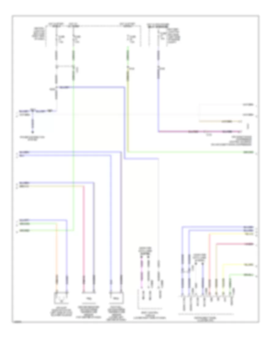
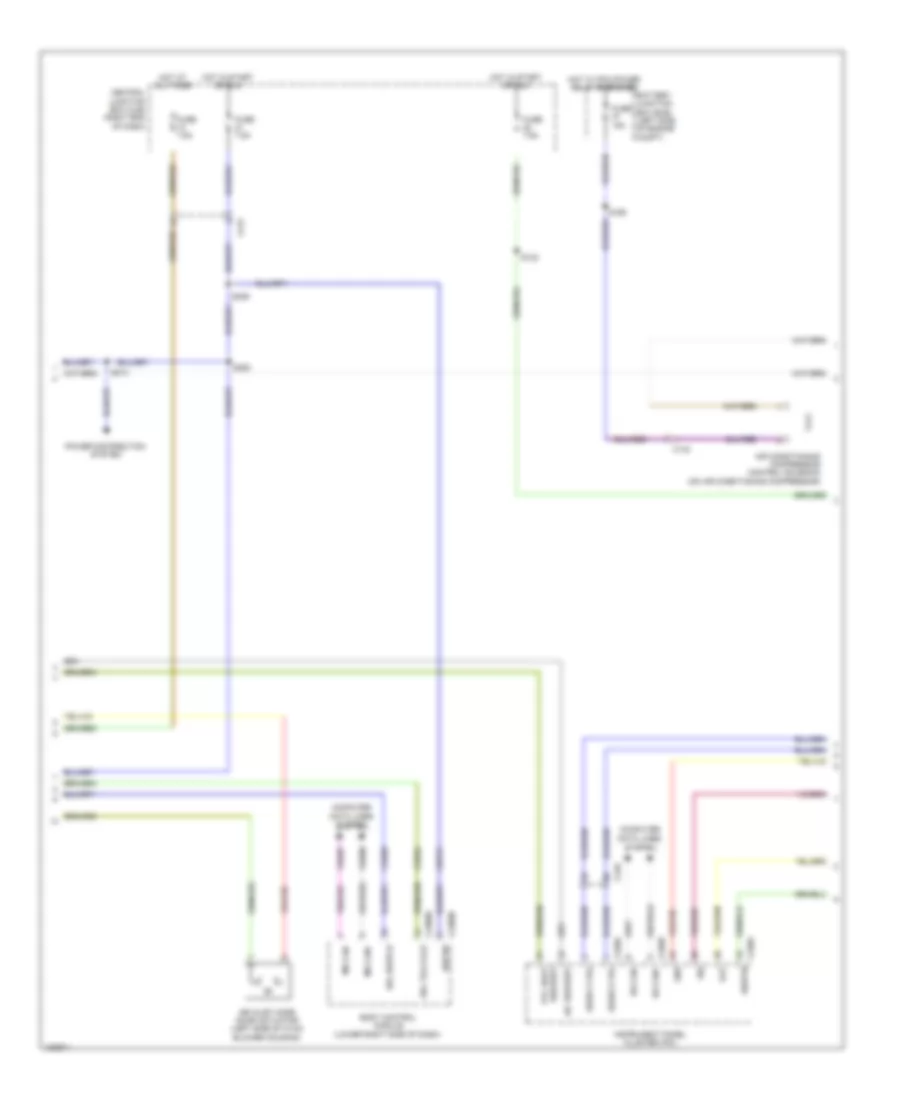
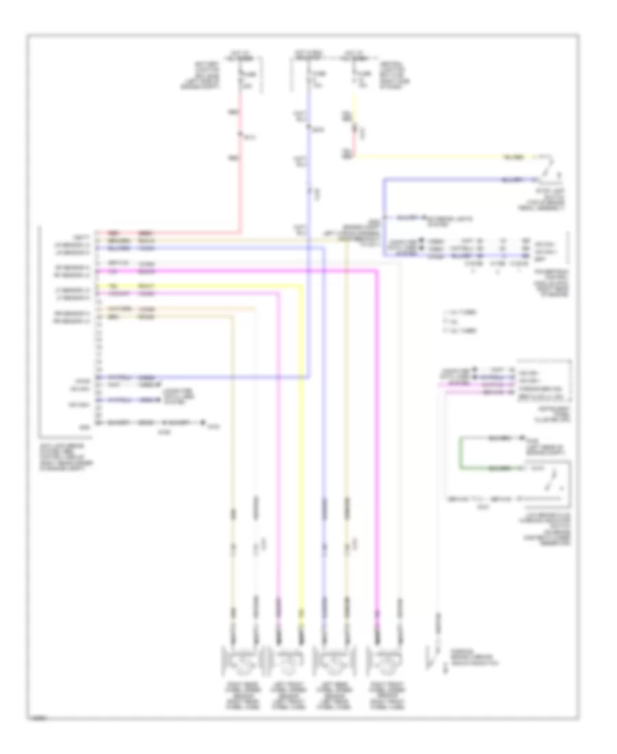
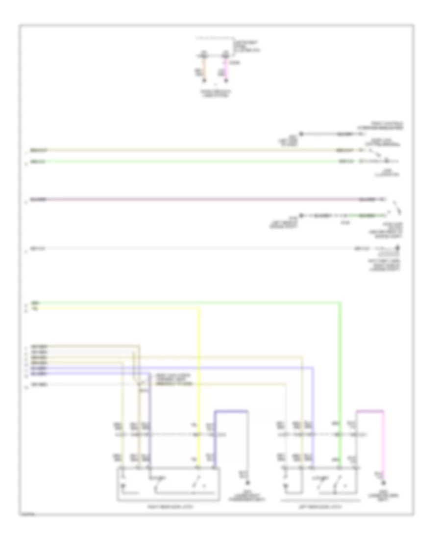
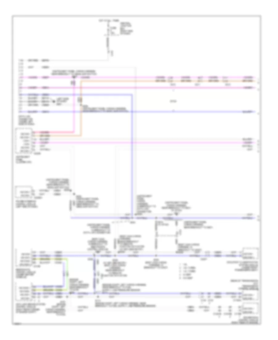
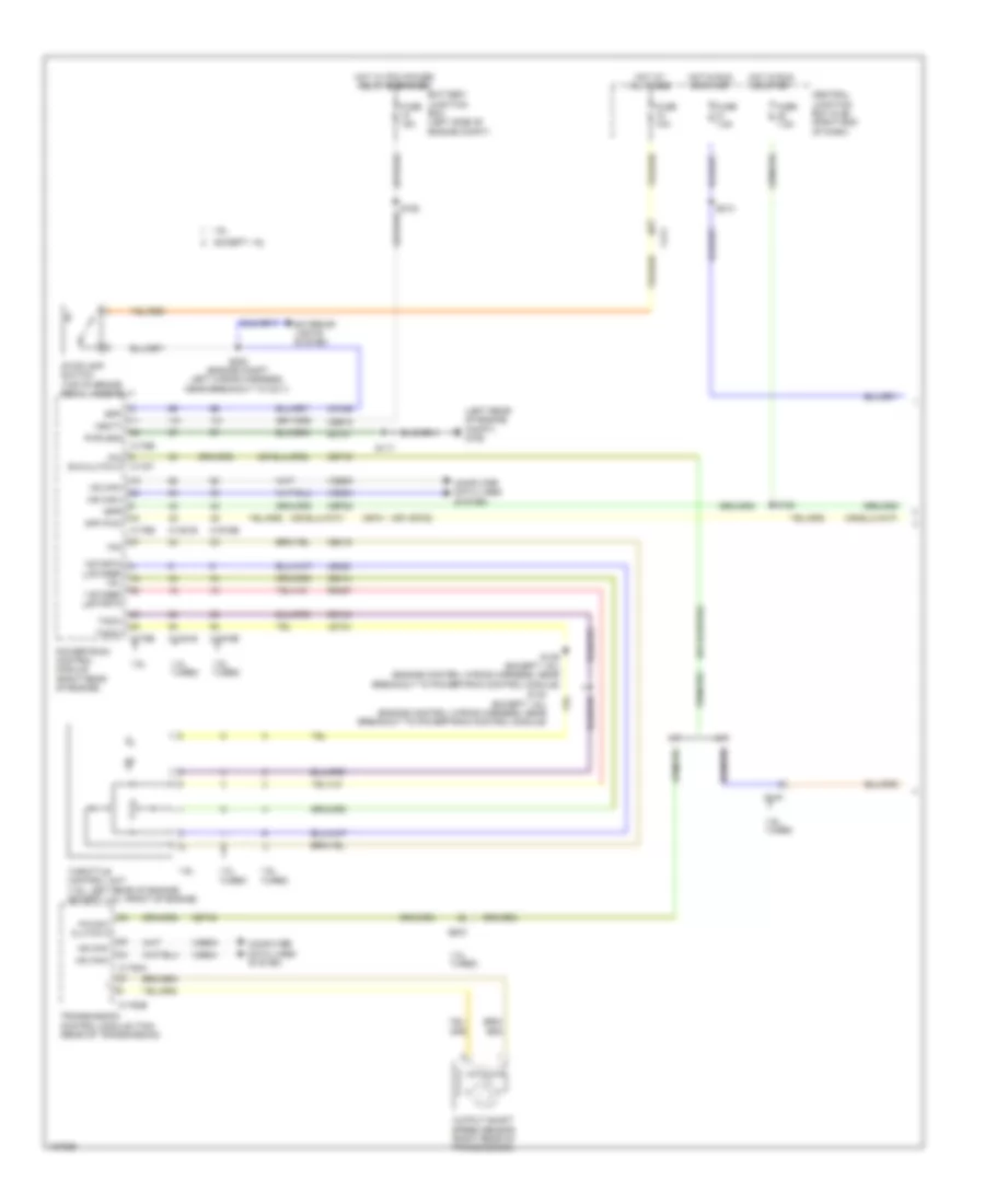
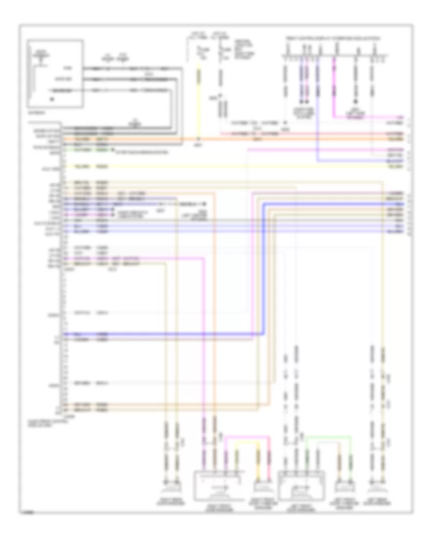
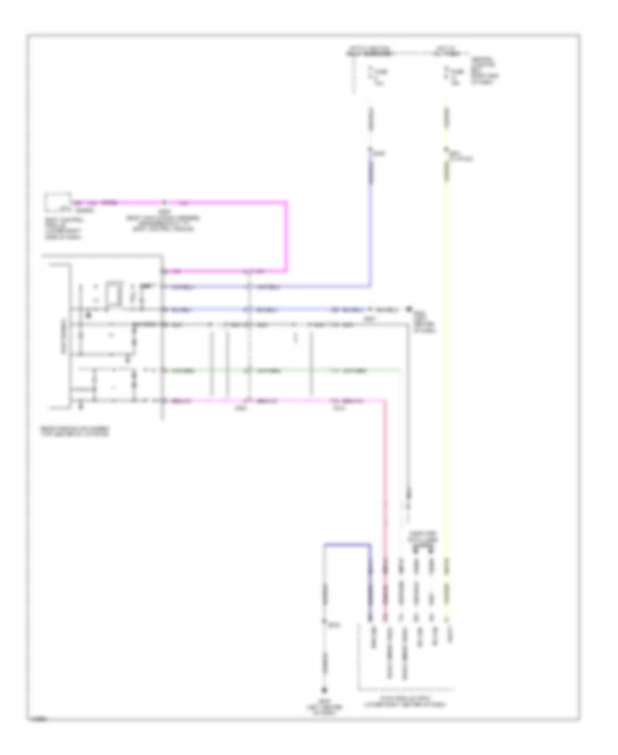
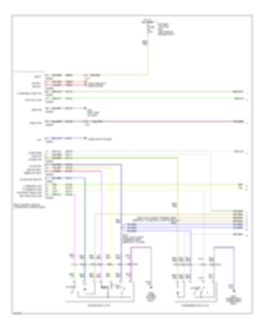
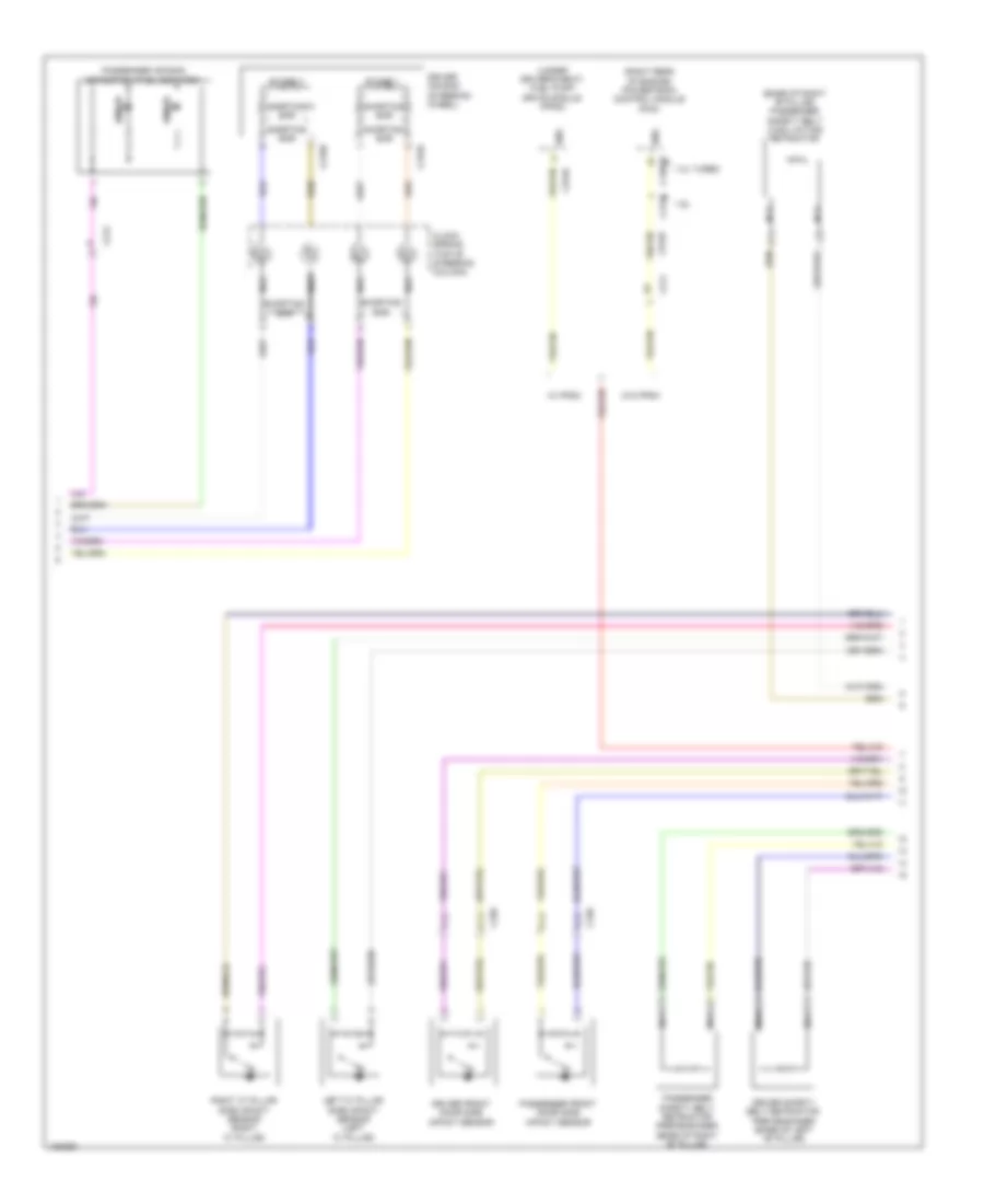
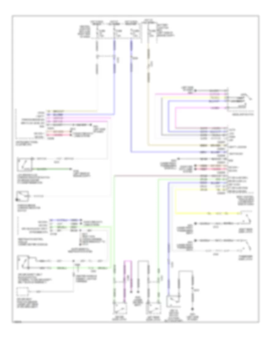
Automatic A/C Wiring Diagram (1 of 4) for Ford Fiesta S 2014
 https://portal-diagnostov.com/license.html
Automotive Electricians Portal FZCO
Automotive Electricians Portal FZCO
https://portal-diagnostov.com/license.html
https://portal-diagnostov.com/license.html
Automotive Electricians Portal FZCO
Automotive Electricians Portal FZCO
List of elements for Automatic A/C Wiring Diagram (1 of 4) for Ford Fiesta S 2014:
- (instrument panel wiring harness, near breakout to ipc)
- (left side of dash) g201
- 1.6l
- A/c clutch relay
- Air conditioning compressor (lower left front of engine)
- Air distribution door actuator (left side of hvac unit)
- Aspirator gnd
- Aspirator pwr
- Battery junction box (bjb) (left side of engine compt)
- Blower cmd
- Blower motor (right side of dash)
- Blower motor control module (lower center of hvac unit)
- Blower motor relay
- C133
- C140
- C210
- C228a
- C228b
- C297a
- C297b
- Ch103
- Ch207
- Ch208
- Ch227
- Ch228
- Ch229
- Ch232
- Ch233
- Ch234
- Ch402
- Cmd
- Computer
- Data lines system
- Electronic automatic temperature control module (eatc)
- Except 1.6l
- Floor sensor
- Fuse 10a
- Fuse 40a
- G109 (left rear of engine compt)
- G112 (left side of engine compt)
- G201 (left side of dash)
- Gd115
- Gnd
- Hot at all times
- Hot w/ pcm power relay energized
- In-vehicle temperature sensor (left center of dash)
- Incar temp sensorl
- Interior lights system
- Lh111
- Mode motor+
- Mode sig
- Motor+
- Motor-
- Ms can+
- Ms can-
- Panel sensor
- Recirc out1
- Recirc out2
- Rh103
- Rh104
- Rh105
- Rh111
- Rh301
- S163
- S231
- S232
- Sbp12
- Sensor gnd
- Sunload sensor (top center of dash)
- Sunload sensor left
- Sunload sensor right
- Temp motor+
- Temp motor-
- Temp sig
- Temperature door actuator (upper right side of hvac unit)
- Vbatt
- Vdb06
- Vdb07
- Vh101
- Vh301
- Vh408
- Vh414
- Vh416
- Vh417
- Vh452
- Vpwr
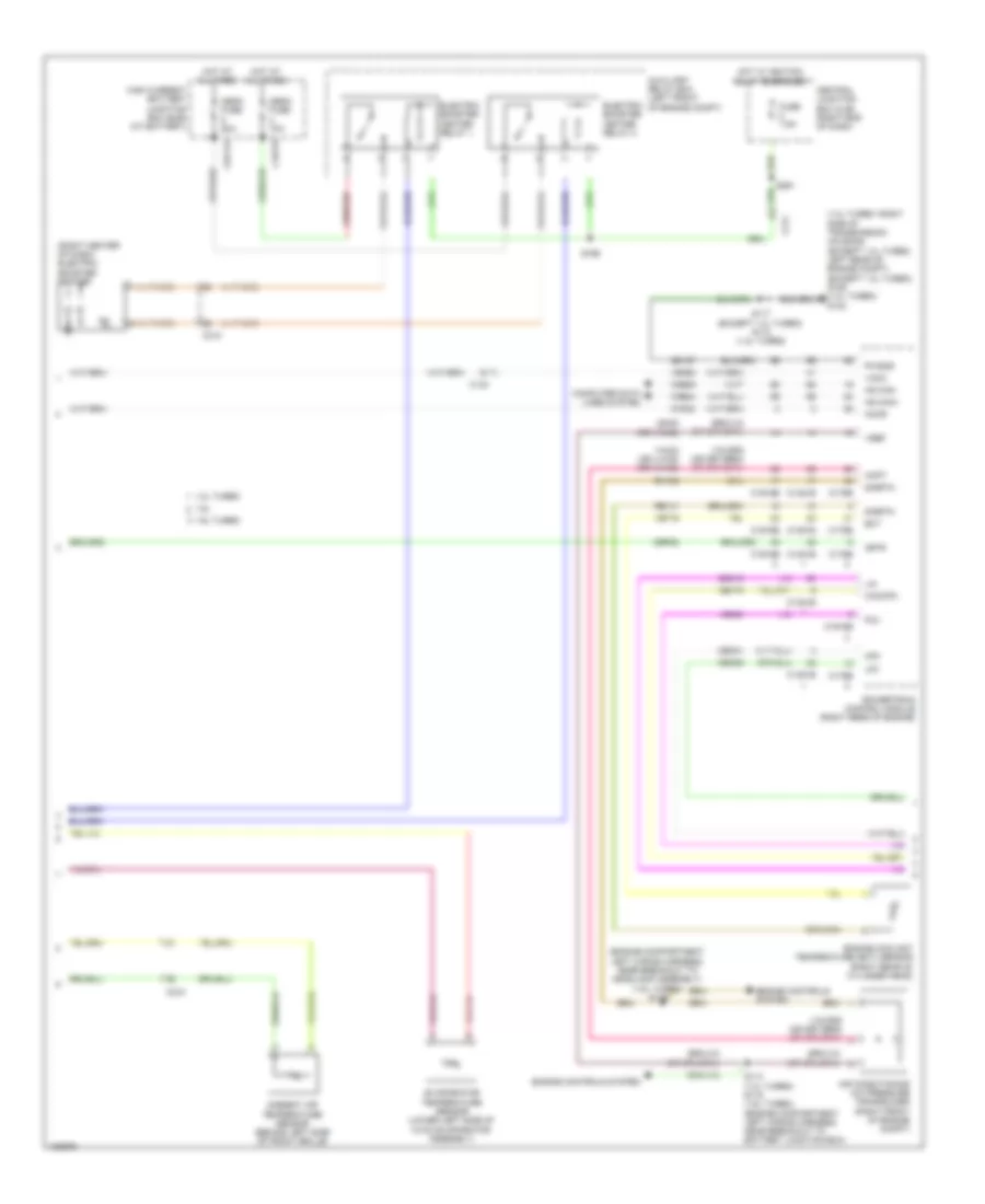
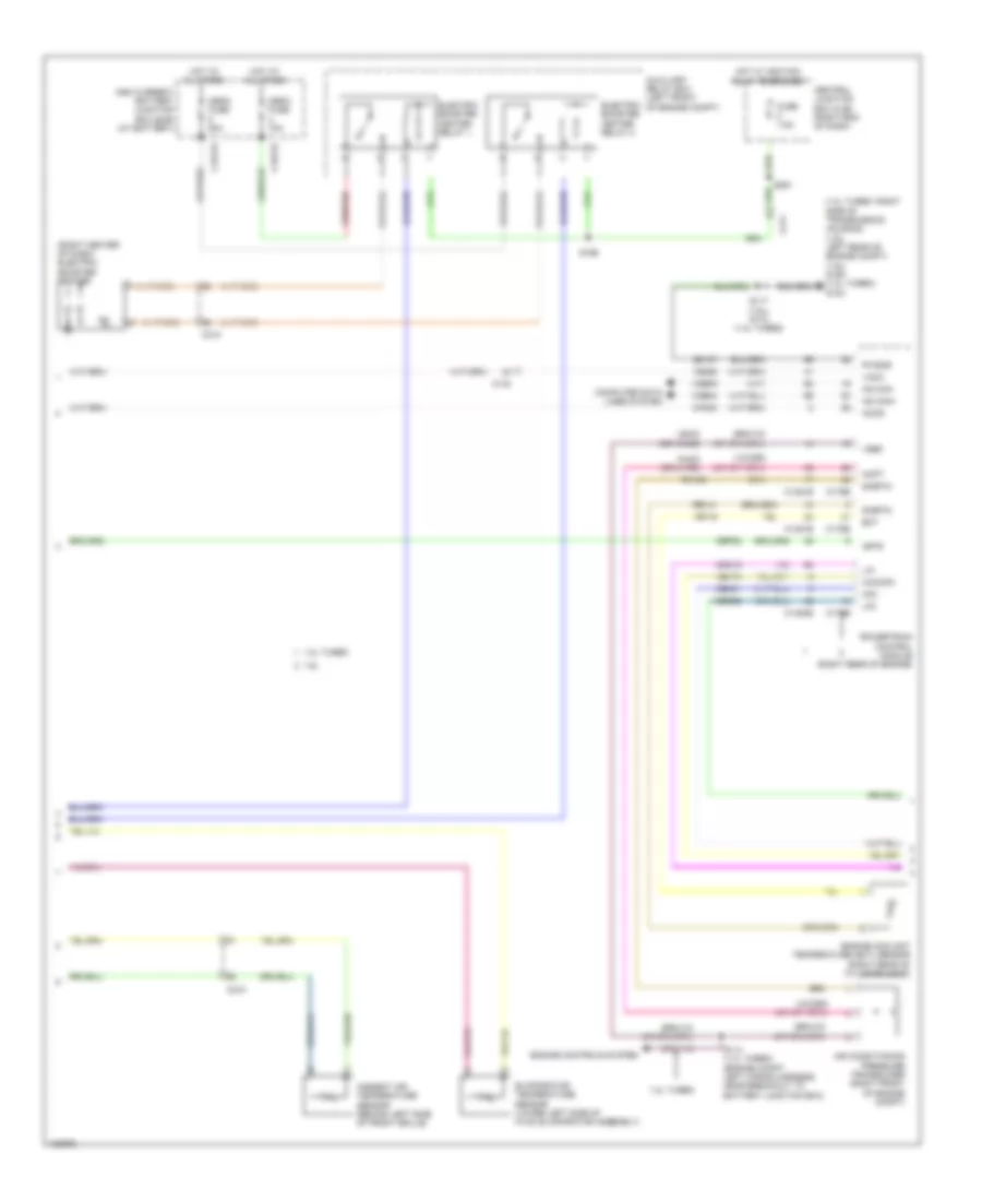
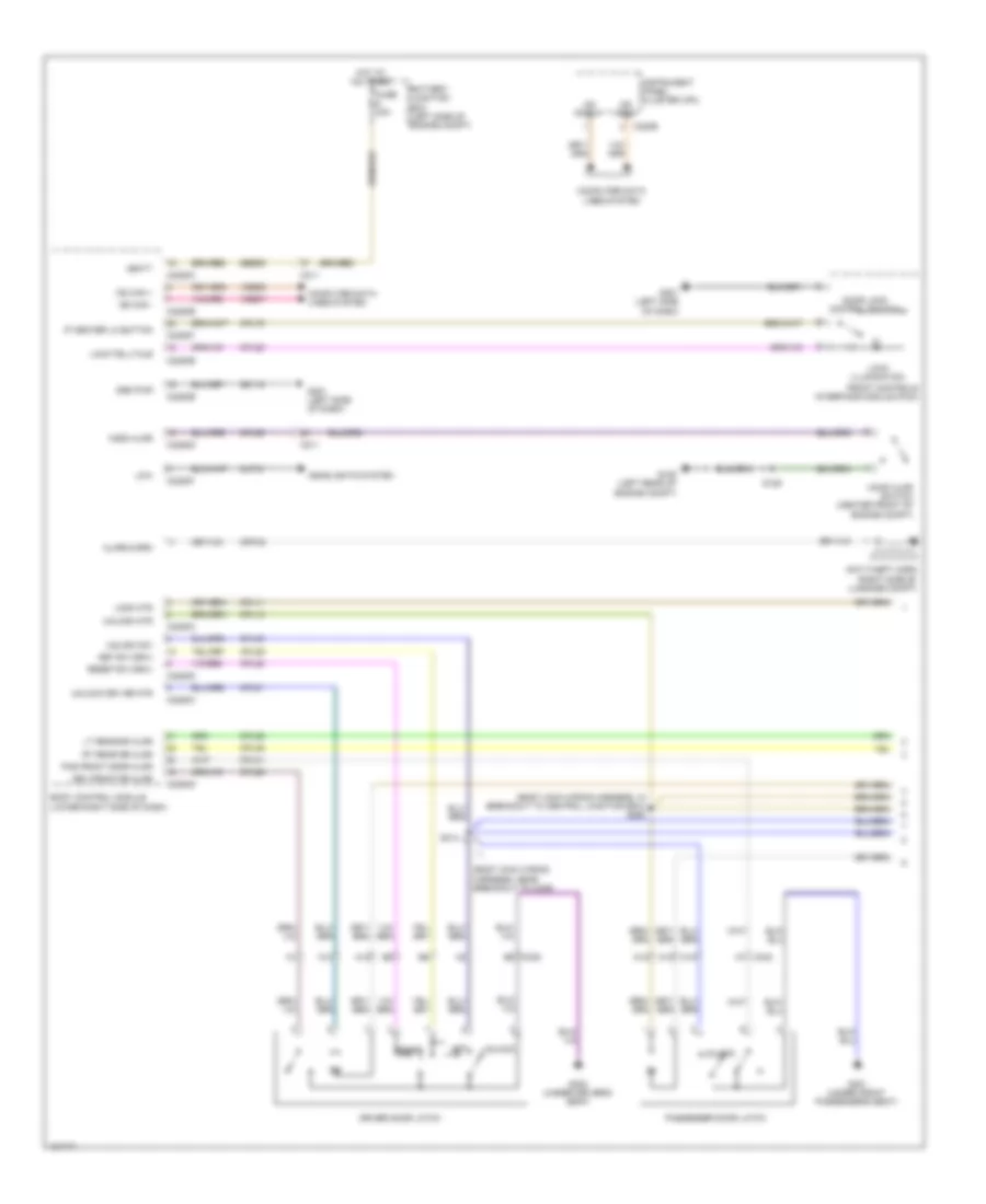
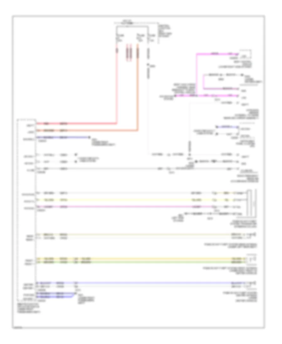
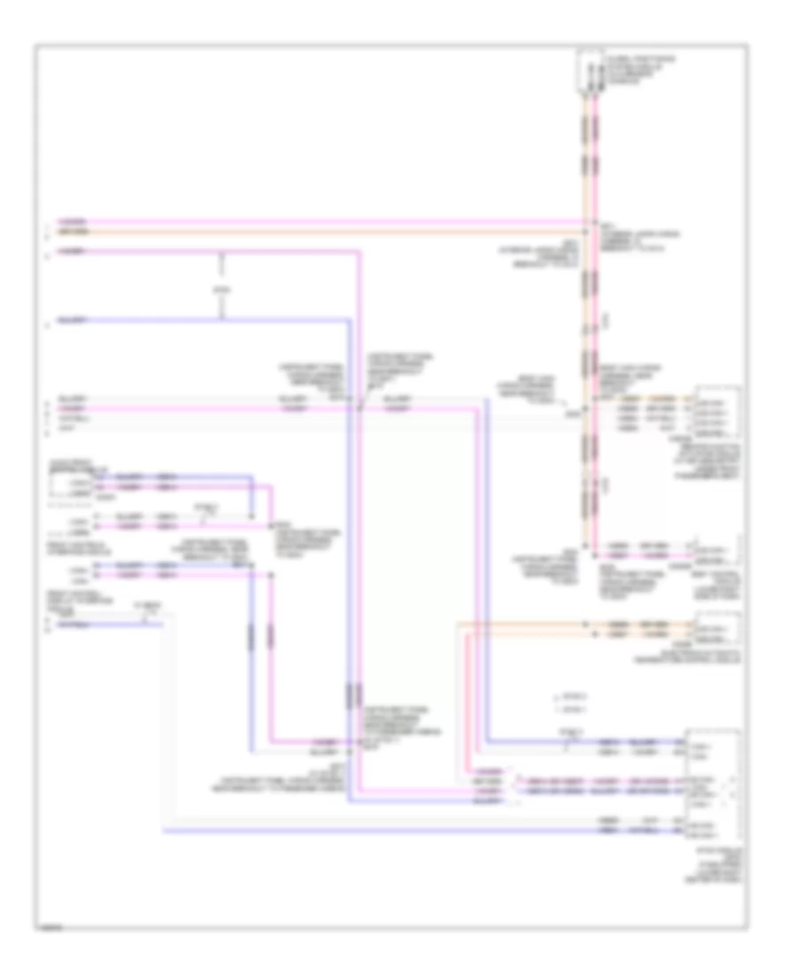
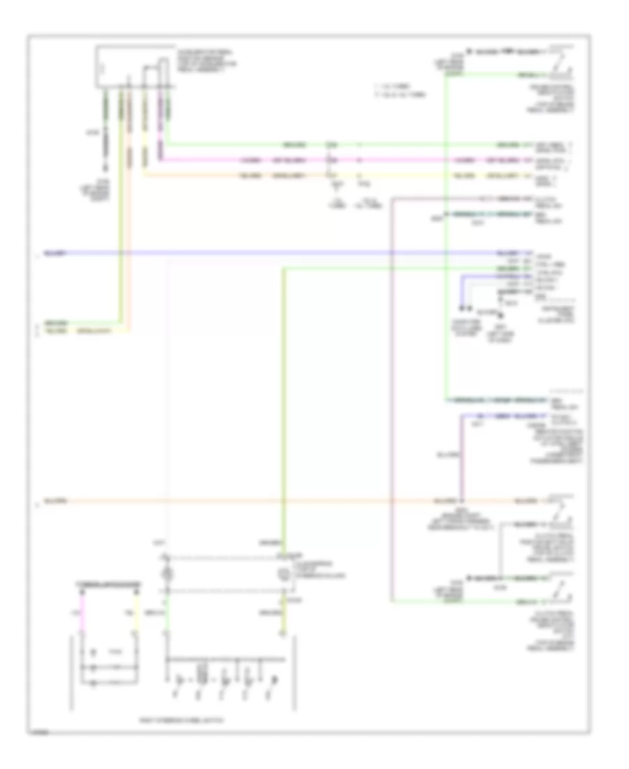
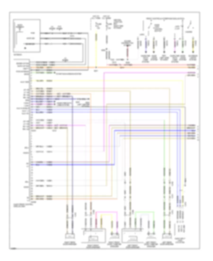
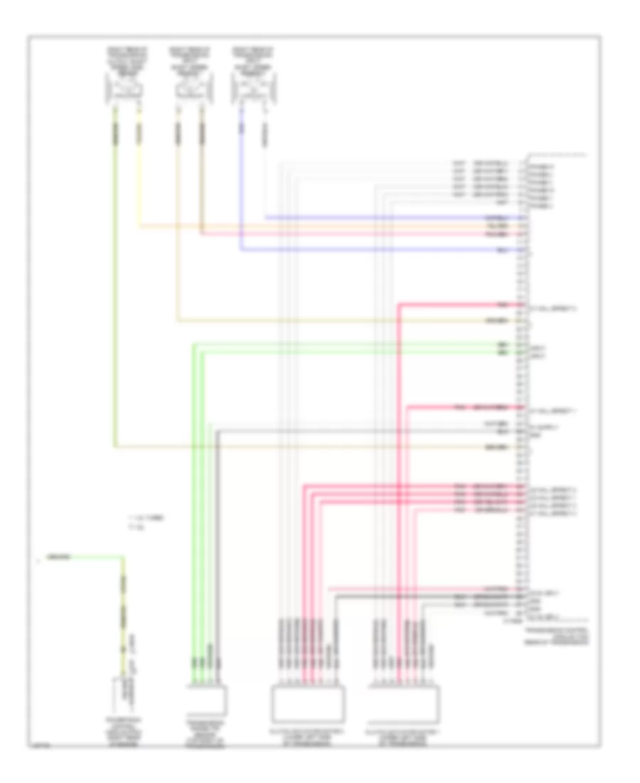
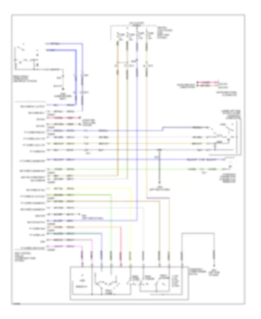
Automatic A/C Wiring Diagram (2 of 4) for Ford Fiesta S 2014
List of elements for Automatic A/C Wiring Diagram (2 of 4) for Ford Fiesta S 2014:
- Aat
- Air conditioning compressor control solenoid (on air conditioning compressor)
- Air inlet door actuator (left side of hvac blower housing)
- Battery junction box (bjb) (left side of engine compt)
- Body control module (lower right side of dash)
- C133
- C210
- C212
- C220a
- C220b
- C2280b
- C2280e
- Cbp21
- Center register air discharge temperature sensor (top center of dash)
- Central junction box (cjb) (right end of dash)
- Computer
- Data lines system
- Ebhr1 ctrl
- Ebhr2 ctrl
- Footwell air discharge temperature sensor (lower left center of dash)
- Fuse 15a
- Fuse 7.5a
- Gnd
- Hot at all times
- Hot in start or run
- Hot w/ pcm power relay energized
- Hs can+
- Hs can-
- Ign sw
- Instrument panel cluster (ipc)
- Ms can+
- Ms can-
- Power distribution system
- S122
- S213
- S228
- Sig
- Sigrtn
- Vdb06
- Vdb07
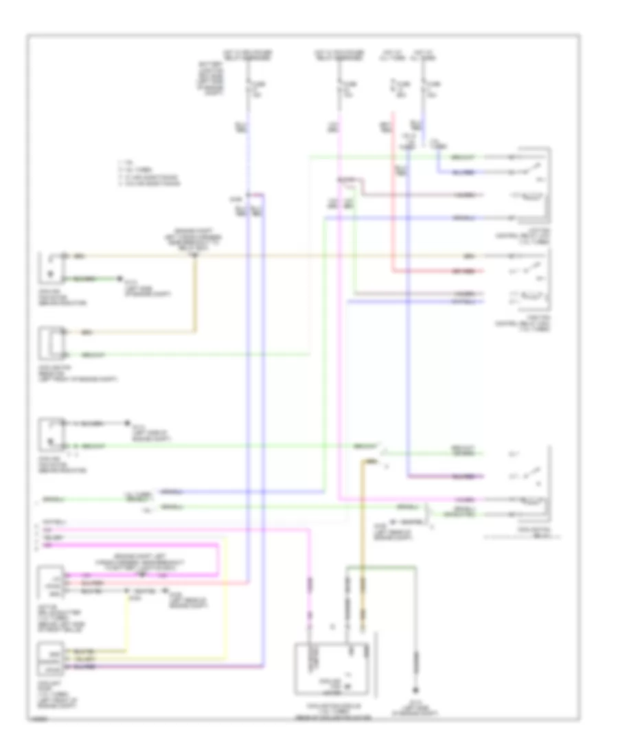
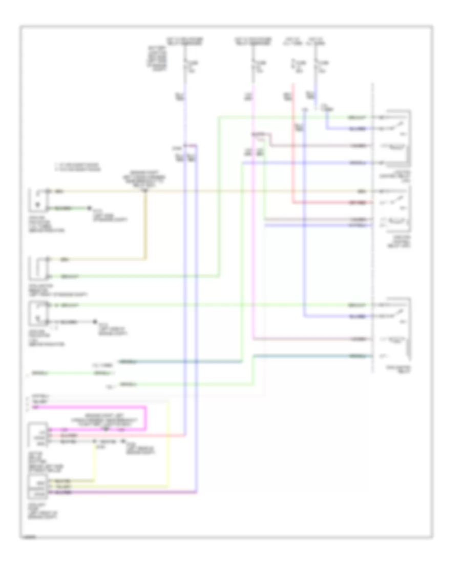
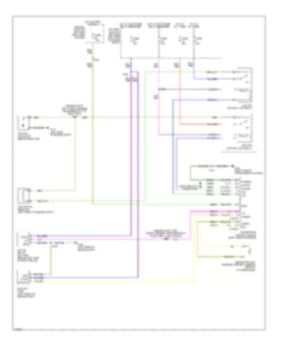
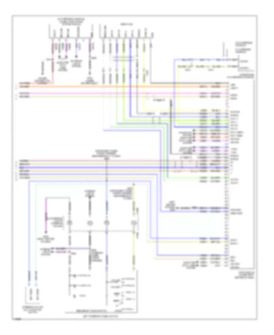
Automatic A/C Wiring Diagram (3 of 4) for Ford Fiesta S 2014
List of elements for Automatic A/C Wiring Diagram (3 of 4) for Ford Fiesta S 2014:
- (1.0l turbo: right side of transmission housing) (except 1.0l turbo: left rear of engine compt) (except 1.0l turbo) g106 (1.0l turbo) g102
- (engine compartment left wiring harness, near breakout to headlamp assembly) (1.6l turbo) s135
- (right center of dash) electric booster heater
- 1.0l turbo
- 1.6l
- 1.6l turbo
- Accr
- Acpt
- Air conditioning a/c pressure transducer (right front of engine compt)
- Ambient air temperature sensor (behind left side of front grille)
- Auxiliary relay box (left front of engine compt)
- C133
- C1381b
- C1381e
- C1617d
- C1617e
- C175b
- C175e
- C1915b
- C1915e
- C210
- C211
- Caccpc
- Cbp22
- Cdc15
- Ce174
- Cec01
- Cec02
- Central junction box (cjb) (right end of dash)
- Ch302
- Computer data lines system
- Ect
- Electric booster heater relay 1
- Electric booster heater relay 2
- Engine controls system
- Engine coolant temperature (ect) sensor (right rear of cylinder head)
- Evaporator temperature sensor (lower left side of hvac evaporator assembly)
- Fcu
- Fuse 7.5a
- Gd187
- Hfc
- High current battery junction box (bjb) (at battery)
- Hot at all times
- Hot w/ ignition relay energized
- Hs can+
- Hs can-
- Isp-r
- Le423 (or vh442)
- Lfc
- Lin
- Mega fuse 50a
- Mega fuse 70a
- Powertrain control module (right rear of engine)
- Pwgnd
- Re141
- Rh108
- S114 (1.0l turbo) s115 (1.6l turbo) (engine compartment left wiring harness, near breakout to battery junction box)
- S117 (except 1.0l turbo) s110 (1.0l turbo)
- S166
- S261
- Sigrtn
- Vacc
- Vdb04
- Vdb05
- Ve230
- Ve462
- Ve716
- Vh433 (or lh108) (or vh442)
- Vref
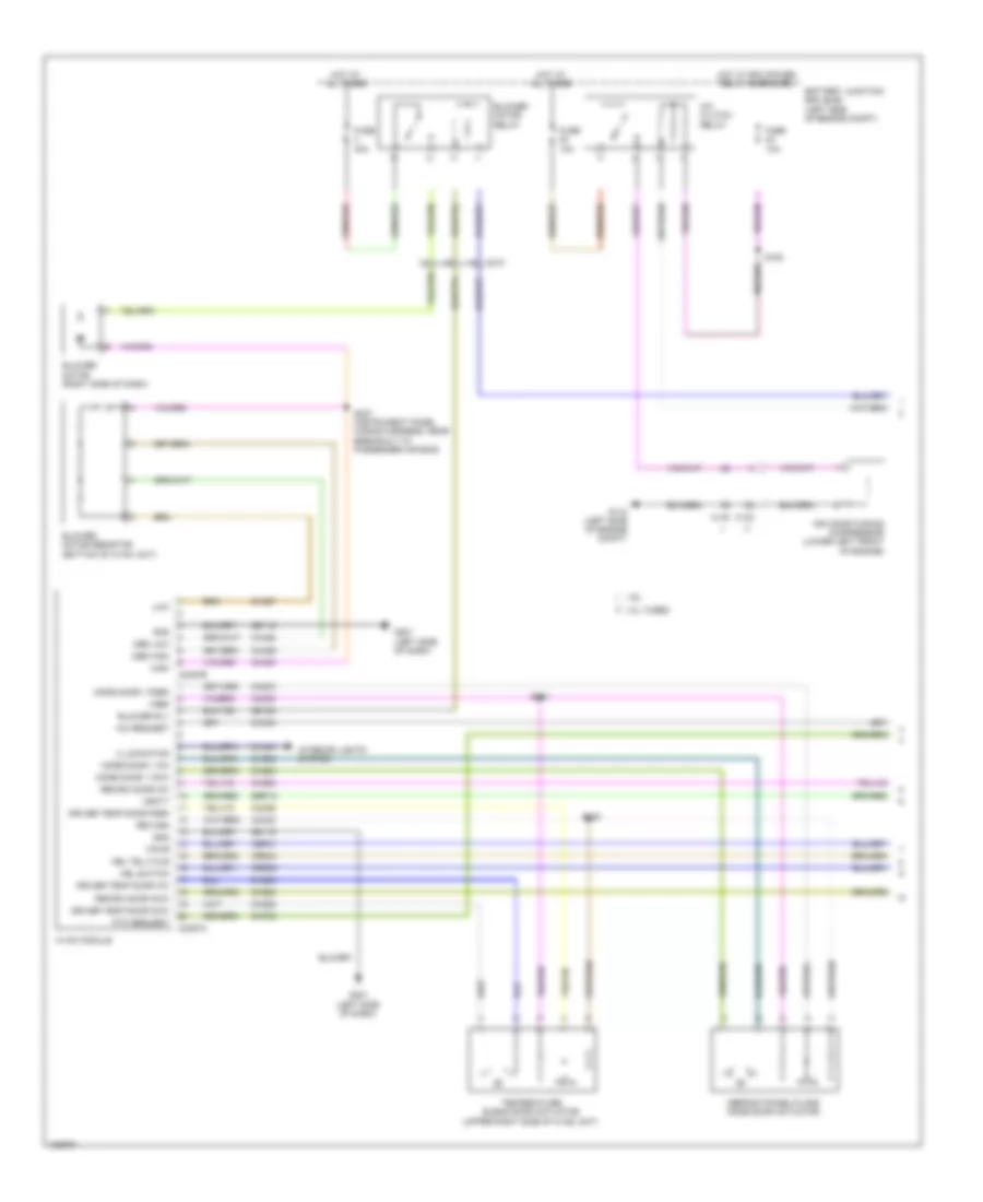
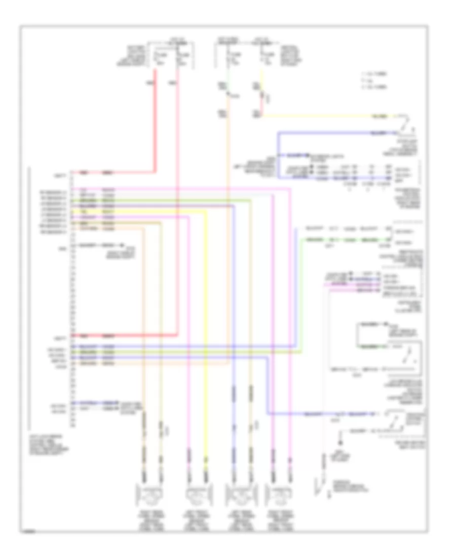
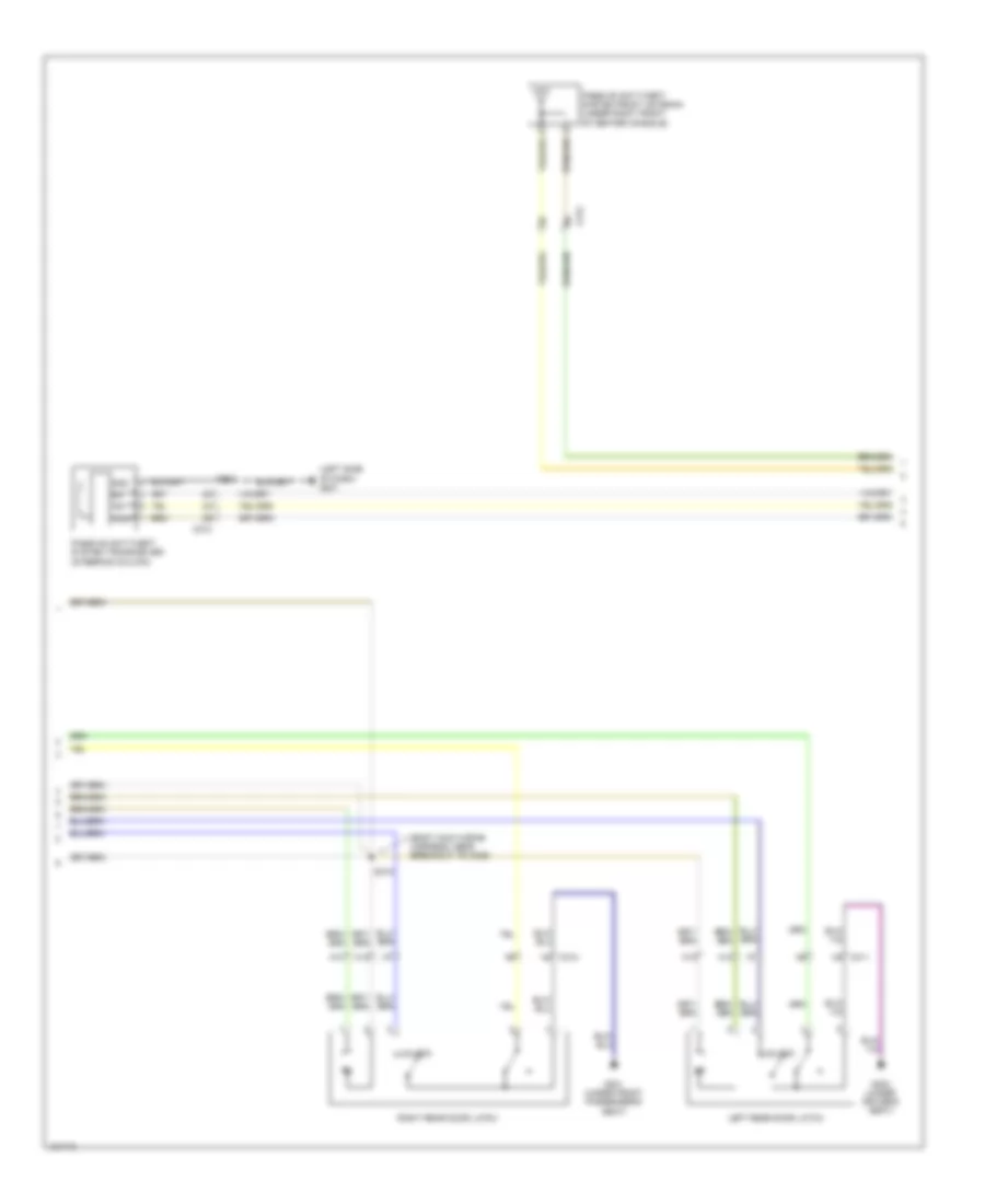
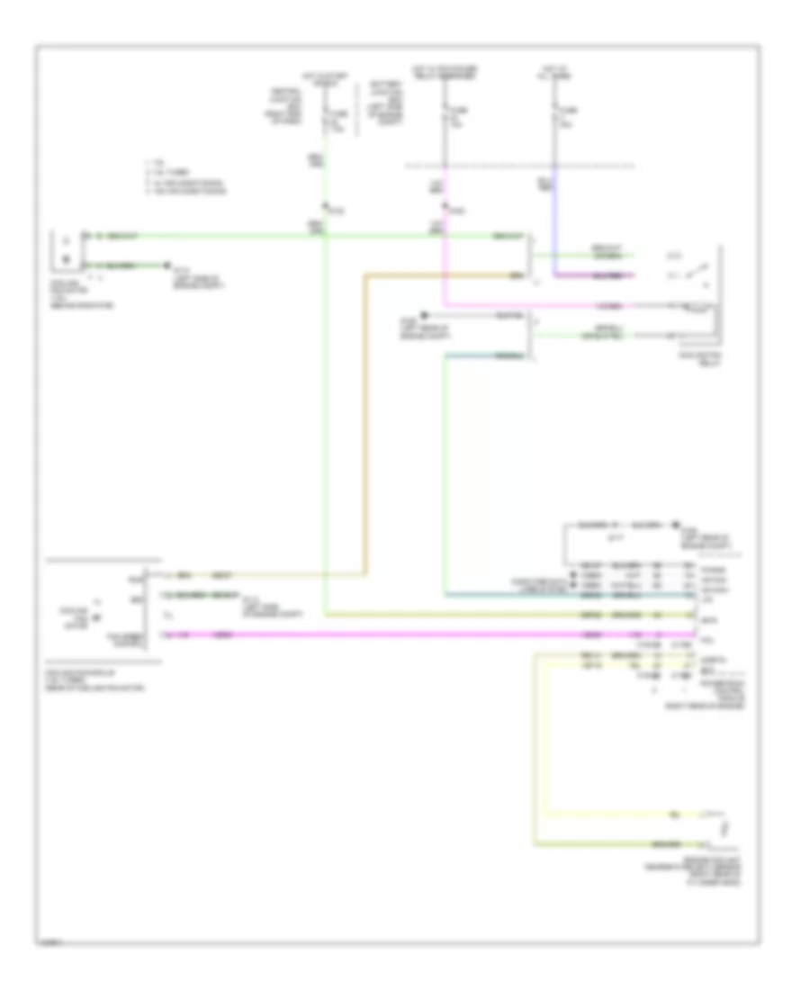
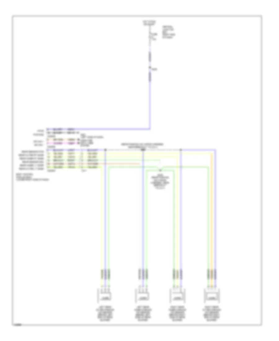
Automatic A/C Wiring Diagram (4 of 4) for Ford Fiesta S 2014
List of elements for Automatic A/C Wiring Diagram (4 of 4) for Ford Fiesta S 2014:
- (engine compt left wiring harness, near breakout to battery junction box) s155
- (engine compt left wiring harness, near breakout to relay box) s111
- 1.0l turbo
- 1.6l
- 1.6l & 1.6l turbo
- 1.6l turbo
- Active grille shutter (1.0l turbo) (behind left side of front grille)
- Battery junction box (bjb) (left side of engine compt)
- Caccpc
- Cec07
- Control fan speed
- Coolant pump (1.0l turbo) (left front of engine compt)
- Cooling fan module (1.6l turbo) (rear of cooling fan motor)
- Cooling fan motor
- Cooling fan motor (behind radiator)
- Cooling fan relay
- Cooling fan resistor (left front of engine compt)
- Fuse 10a
- Fuse 15a
- Fuse 40a
- Fuse 60a
- G109 (left rear of engine compt)
- G113 (left side of engine compt)
- Gd120
- Gnd
- High fan control relay (hfc) (1.0l turbo)
- Hot at all times
- Hot w/ pcm power relay energized
- Lin
- Low fan control relay (lfc) (1.0l turbo)
- Pwr
- S163
- S164
- S165
- Ve230
- Vpwr
- W/ air conditioning w/o air conditioning
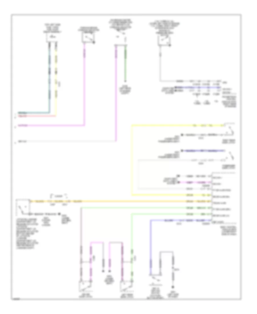
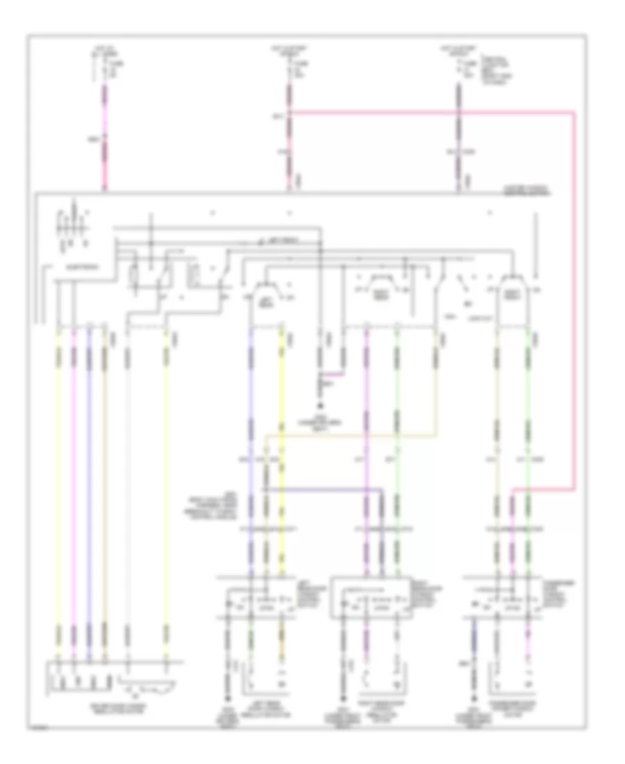
Manual A/C Wiring Diagram (1 of 4) for Ford Fiesta S 2014
List of elements for Manual A/C Wiring Diagram (1 of 4) for Ford Fiesta S 2014:
- 1.0l turbo
- 1.6l
- A/c clutch relay
- A/c request
- Air conditioning compressor (lower left front of engine)
- Battery junction box (bjb) (left side of engine compt)
- Blower motor (right side of dash)
- Blower motor relay
- Blower motor resistor (bottom of hvac unit)
- Blower rly
- C133
- C140
- C210
- C2357a
- C2357b
- Cbp21
- Ch202
- Ch203
- Ch204
- Ch206
- Ch208
- Ch232
- Ch233
- Ch235
- Ch236
- Ch427
- Ch428
- Ch429
- Ch430
- Ch434
- Chp03
- Cln04
- Crd04
- Crd09
- Defrost/panel/floor mode door actuator
- Driver temp door ccw
- Driver temp door cw
- Driver temp door fdbk
- Fuse 10a
- Fuse 40a
- G112 (left side of engine compt)
- G201 (left side of dash)
- Gd115
- Gd188
- Gnd
- Hbl switch
- Hbl telltale
- High
- Hot at all times
- Hot w/ pcm power relay energized
- Hvac module
- Illumination
- Interior lights system
- Low
- Med high
- Med low
- Mode door 1 ccw
- Mode door 1 cw
- Mode door 1 fdbk
- Ptc request
- Recirc door ccw
- Recirc door cw
- Return
- S163
- S220
- S221
- S237 (instrument panel wiring harness, near breakout to passenger air bag)
- Sbp12
- Temperature blend door actuator (upper right side of hvac unit)
- Vbatt
- Vpwr
- Vref
Manual A/C Wiring Diagram (2 of 4) for Ford Fiesta S 2014
List of elements for Manual A/C Wiring Diagram (2 of 4) for Ford Fiesta S 2014:
- A/c request
- Aat
- Air conditioning compressor control solenoid (on air conditioning compressor)
- Air inlet mode door actuator (left side of hvac blower housing)
- Battery junction box (bjb) (left side of engine compt)
- Body control module (lower right side of dash)
- C133
- C210
- C212
- C220a
- C220b
- C2280b
- C2280e
- Cbp21
- Central junction box (cjb) (right end of dash)
- Computer
- Crd04
- Crd09
- Data lines system
- Ebhr1 ctrl
- Ebhr2 ctrl
- Fuse 15a
- Fuse 7.5a
- Gnd
- Hbl switch
- Hbl telltale
- Hot at all times
- Hot in start or run
- Hot w/ pcm power relay energized
- Hs can+
- Hs can-
- Ign sw
- Instrument panel cluster (ipc)
- Ms can+
- Ms can-
- Power distribution system
- Request ptc heat
- S122
- S165
- S213
- S228
- S239
- Sig
- Sigrtn
- Vdb06
- Vdb07
Manual A/C Wiring Diagram (3 of 4) for Ford Fiesta S 2014
List of elements for Manual A/C Wiring Diagram (3 of 4) for Ford Fiesta S 2014:
- (1.0l turbo: right side of transmission housing) (1.6l: left rear of engine compt) (1.6l) g106 (1.0l turbo) g102
- (right center of dash) electric booster heater
- 1.0l turbo
- 1.6l
- Accr
- Acpt
- Air conditioning pressure transducer (right front of engine compt)
- Ambient air temperature sensor (behind left side of front grille)
- Auxiliary relay box (left front of engine compt)
- C133
- C1381b
- C1381e
- C1617d
- C1617e
- C175b
- C175e
- C210
- C211
- Caccpc
- Cbp22
- Cdc15
- Ce174
- Cec01
- Cec02
- Central junction box (cjb) (right end of dash)
- Ch302
- Computer data lines system
- Ect
- Electric booster heater relay 1
- Electric booster heater relay 2
- Engine controls system
- Engine coolant temperature (ect) sensor (right rear of cylinder head)
- Evaporator temperature sensor (lower left side of hvac evaporator assembly)
- Fuse 7.5a
- Gd187
- Hfc
- High current battery junction box (bjb) (at battery)
- Hot at all times
- Hot w/ ignition relay energized
- Hs can+
- Hs can-
- Isp-r
- Le423 (or vh442)
- Lfc
- Lin
- Mega fuse 50a
- Mega fuse 70a
- Powertrain control module (right rear of engine)
- Pwgnd
- Re141
- Rh108
- S114 (1.0l turbo) (engine compt left wiring harness, near breakout to battery junction box)
- S117 (1.6l) s110 (1.0l turbo)
- S166
- S261
- Sigrtn
- Vacc
- Vdb04
- Vdb05
- Ve462
- Ve716
- Vh433 (or lh108)
- Vref
Manual A/C Wiring Diagram (4 of 4) for Ford Fiesta S 2014
List of elements for Manual A/C Wiring Diagram (4 of 4) for Ford Fiesta S 2014:
- (engine compt left wiring harness, near breakout to battery junction box) s155
- (engine compt left wiring harness, near breakout to relay box) s111
- 1.0l turbo
- 1.6l
- Active grille shutter (behind left side of front grille)
- Battery junction box (bjb) (left side of engine compt)
- Caccpc
- Coolant pump (left front of engine compt)
- Cooling fan motor (1.0l turbo) (behind radiator)
- Cooling fan motor (1.6l) (behind radiator)
- Cooling fan relay
- Cooling fan resistor (left front of engine compt)
- Fuse 10a
- Fuse 15a
- Fuse 40a
- Fuse 60a
- G109 (left rear of engine compt)
- G113 (left side of engine compt)
- Gnd
- High fan control relay (hfc)
- Hot at all times
- Hot w/ pcm power relay energized
- Lin
- Low fan control relay (lfc)
- S163
- S164
- S165
- Vpwr
- W/ air conditioning w/o air conditioning
ANTI-LOCK BRAKES
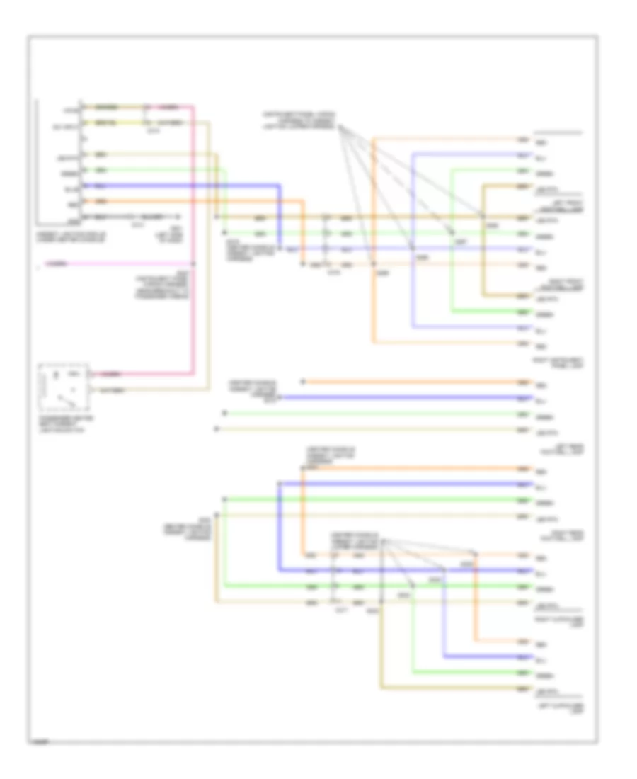
Anti-lock Brakes Wiring Diagram, with Electronic Stability Program for Ford Fiesta S 2014
List of elements for Anti-lock Brakes Wiring Diagram, with Electronic Stability Program for Ford Fiesta S 2014:
- 1.0l turbo
- 1.6l
- 1.6l turbo
- Anti-lock brake system (abs) control module (right rear corner of engine compt)
- Battery junction box (bjb) (left side of engine compt)
- Bpp
- Brk fluid lvl sw
- C1381b
- C175b
- C1915b
- C210
- C211
- C310b
- Cbp22
- Cca26
- Cca47
- Central junction box (cjb) (right end of dash)
- Computer data lines system
- Driver heated seat switch
- Esp sw
- Exterior lights system
- Fuse 10a
- Fuse 60a
- Fuse 7.5a
- G106 (left rear of engine compt)
- G108 (right side of engine compt)
- G201 (left side of dash)
- Gd123
- Gnd
- Hot at all times
- Hot in run or start
- Hs can +
- Hs can -
- Hs can+
- Hs can-
- Hs can2 +
- Hs can2 -
- Instrument panel cluster (ipc)
- Left front wheel speed sensor (left front wheel hubs)
- Left rear wheel speed sensor (left rear wheel hubs)
- Lf sensor hi
- Lf sensor lo
- Low brake fluid warning indicator switch (on brake master cylinder reservoir)
- Lr sensor hi
- Lr sensor lo
- Nca
- Parking brake warning indicator switch
- Parking brk sig
- Powertrain control module (pcm) (right rear of engine)
- Rca17
- Rca18
- Rca19
- Rca20
- Red
- Restraints control module (rcm) (under center console)
- Rf sensor hi
- Rf sensor lo
- Right front wheel speed sensor (right front wheel hubs)
- Right rear wheel speed sensor (right rear wheel hubs)
- Rr sensor hi
- Rr sensor lo
- S122
- S202 (engine compt left wiring harness, near breakout to c211)
- Sbb01
- Sbb09
- Stoplamp switch (top of brake pedal assembly)
- Traction control switch
- Vbatt
- Vca03
- Vca04
- Vca05
- Vca06
- Vca23
- Vca24
- Vdb04
- Vdb05
- Vpwr
Anti-lock Brakes Wiring Diagram, without Electronic Stability Program for Ford Fiesta S 2014
List of elements for Anti-lock Brakes Wiring Diagram, without Electronic Stability Program for Ford Fiesta S 2014:
- 1.0l turbo
- 1.6l
- 1.6l turbo
- Anti-lock brake system (abs) control module (right rear corner of engine compt)
- Battery junction box (bjb) (left side of engine compt)
- Bpp
- Brk fluid lvl sw
- C1381b
- C175b
- C1915b
- C210
- C211
- C215
- Cca26
- Central junction box (cjb) (right side of dash)
- Computer data lines system
- Cpb06
- Exterior lights system
- Fuse 10a
- Fuse 40a
- G103
- G106 (left rear of engine compt)
- Gd123
- Gnd
- Hot at all times
- Hot in run or start
- Hs can +
- Hs can -
- Hs can+
- Hs can-
- Instrument panel cluster (ipc)
- Left front wheel speed sensor (left front wheel hubs)
- Left rear wheel speed sensor (left rear wheel hubs)
- Lf sensor hi
- Lf sensor lo
- Low brake fluid warning indicator switch (on brake master cylinder reservoir)
- Lr sensor hi
- Lr sensor lo
- Nca
- Parking brake warning indicator switch
- Parking brk sig
- Powertrain control module (pcm) (right rear of engine)
- Rca17
- Rca18
- Rca19
- Rca20
- Red
- Rf sensor hi
- Rf sensor lo
- Right front wheel speed sensor (right front wheel hubs)
- Right rear wheel speed sensor (right rear wheel hubs)
- Rr sensor hi
- Rr sensor lo
- S113
- S129
- S202 (engine compt left wiring harness, near breakout to c211)
- S276
- Sbb01
- Stop lamp switch (top of brake pedal assembly)
- Vbatt
- Vca03
- Vca04
- Vca05
- Vca06
- Vdb04
- Vdb05
- Vpwr
ANTI-THEFT
Forced Entry Wiring Diagram, with Keyless Entry (1 of 4) for Ford Fiesta S 2014
List of elements for Forced Entry Wiring Diagram, with Keyless Entry (1 of 4) for Ford Fiesta S 2014:
- (body main wiring harness, in breakout to central junction box) s260
- (body main wiring harness, near breakout to c339)
- A1 c340
- A10
- A12
- A13
- Alarm horn
- Anti-theft horn (right side of luggage compt)
- B5 c339
- Battery junction box (left side of engine compt)
- Body control module (lower right side of dash)
- C211
- C220b
- C2280b
- C2280c
- C2280d
- C2280e
- C2280f
- C2280g
- Clf18
- Computer data lines system
- Cpl11
- Cpl13
- Cpl22
- Cpl25
- Cpl26
- Cpl28
- Cpl29
- Cpl30
- Cpl31
- Cpl36
- Cpl39
- Cpl51
- Cpl75
- Crt02
- Door lock control switch
- Driver door latch
- Drv front dr ajar
- Front controls interface module (fcim)
- Fuse 30a
- G106 (left rear of engine compt)
- G201 (left side of dash)
- G301 (under front passenger's seat)
- G302 (under driver's seat)
- Gd115
- Gnd pwr
- Headlights system
- Hood ajar
- Hood ajar switch (center front of engine compt)
- Hot at all times
- Instrument panel cluster (ipc)
- Ip center lk button
- Lock illumination
- Lock mtr
- Lock telltale
- Low
- Lt rear dr ajar
- Ms can +
- Ms can -
- Pas front door ajar
- Passenger door latch
- Reset
- Reset sw (drv)
- Rt rear dr ajar
- S129
- S314
- Sbb06
- Set
- Set sw (drv)
- Unlock
- Unlock drv dr mtr
- Unlock mtr
- Unlock sw
- Vbatt
- Vdb06
- Vdb07
Forced Entry Wiring Diagram, with Keyless Entry (2 of 4) for Ford Fiesta S 2014
List of elements for Forced Entry Wiring Diagram, with Keyless Entry (2 of 4) for Ford Fiesta S 2014:
- (body main wiring harness, near breakout to c339)
- (left side of dash) g201
- A12
- A13
- A4 c311
- A4 c312
- C212
- G301 (under front passenger's seat)
- G302 (under driver's seat)
- Gnd
- Left rear door latch
- Passive anti-theft system front antenna (under right front of center console)
- Passive anti-theft system transceiver (steering column)
- Pwr
- Right rear door latch
- S218
- S315
- Unlock
Forced Entry Wiring Diagram, with Keyless Entry (3 of 4) for Ford Fiesta S 2014
List of elements for Forced Entry Wiring Diagram, with Keyless Entry (3 of 4) for Ford Fiesta S 2014:
- Ant +
- Ant -
- C212
- C3503a
- C3503d
- C3503e
- C495
- Cbp13
- Center +
- Center -
- Central junction box (right end of dash)
- Front +
- Front -
- Fuse 20a
- Fuse 7.5a
- G301 (under front passenger's seat)
- Gd145
- Hot at all times
- Keyless entry rear antenna (behind center of rear bumper)
- Left +
- Left -
- Logic
- Passive anti-theft system center antenna (under center center console)
- Passive anti-theft system rear antenna (under left rear seat)
- Pats pwr
- Pats rx
- Pats tx
- Pwr gnd
- Rear +
- Rear -
- Red
- Remote function actuator module (under front passenger's seat)
- Right +
- Right -
- Rpk01
- Rpk02
- Rpk05
- Rpk06
- Rpk07
- Rpk08
- S262
- Sbp09
- Sbp14
- Sig gnd 1
- Sig gnd 2
- Vbatt
- Vpk01
- Vpk02
- Vpk05
- Vpk06
- Vpk07
- Vpk08
- Vrt23
- Vrt24
Forced Entry Wiring Diagram, with Keyless Entry (4 of 4) for Ford Fiesta S 2014
List of elements for Forced Entry Wiring Diagram, with Keyless Entry (4 of 4) for Ford Fiesta S 2014:
- A10
- Anti-theft system
- Brake pedal sw
- C213
- C339
- C340
- C3503b
- C3503c
- C3503d
- Cca25
- Cdc32
- Cdc35
- Cdc41
- Ce903
- Clutch 2
- Computer data lines system
- Cpk34
- Cpk35
- Cpl10
- Cpl27
- Cpl32
- Cruise control system
- G301 (under front passenger's seat)
- G302 (under driver's seat)
- Gnd
- Hs can +
- Hs can -
- Ign monitor
- K-line
- K-line irx
- Left front exterior door handle
- Ms can +
- Ms can -
- Park detect sw
- Power distribution system
- Radio frequency receiver (in overhead console)
- Release sw
- Remote function actuator module (under front passenger's seat)
- Right front exterior door handle
- Run/acc output
- S905
- S914
- Shift interlock system
- Smcs
- Ssb 1
- Ssb 2
- Start/run out
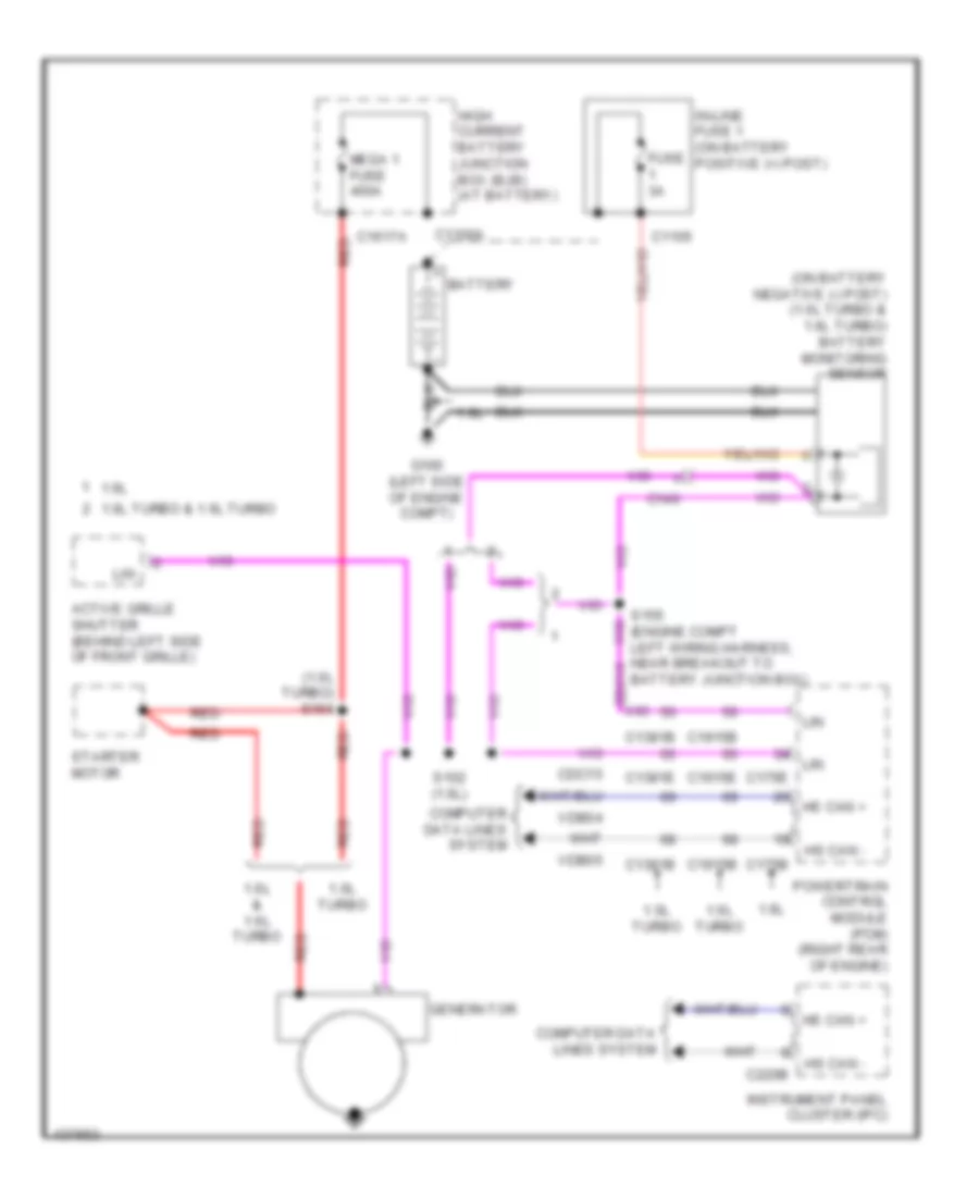
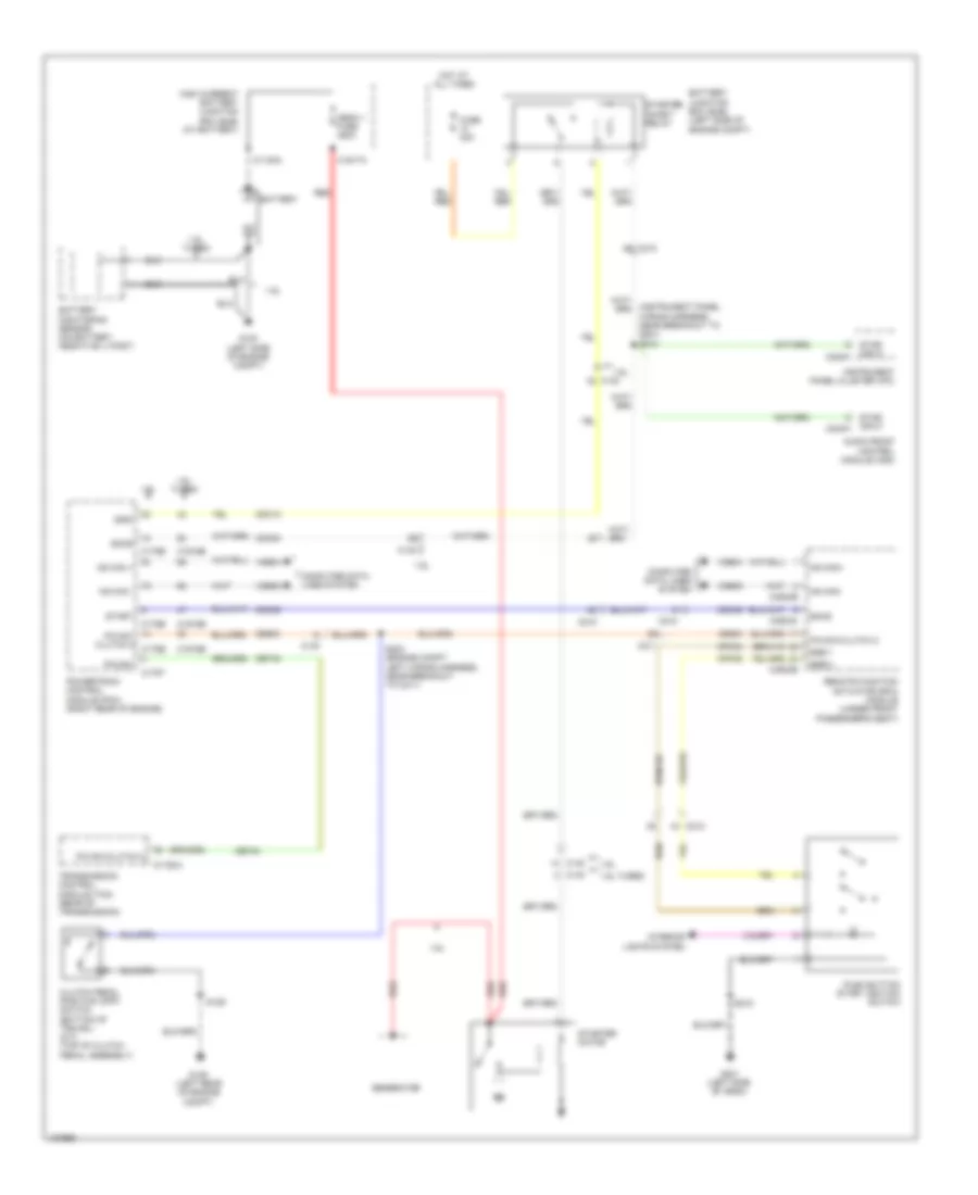
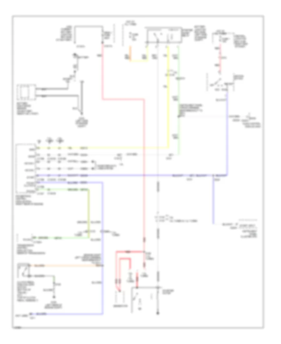
- Starting/charging system
- Sw left
- Sw right
- Trunk, tailgate, fuel doors system
- Vbatt
- Vdb04
- Vdb05
- Vdb06
- Vdb07
- Vdb10
- Za101
- Za102
Forced Entry Wiring Diagram, without Keyless Entry (1 of 2) for Ford Fiesta S 2014
List of elements for Forced Entry Wiring Diagram, without Keyless Entry (1 of 2) for Ford Fiesta S 2014:
- (body main wiring harness, near breakout to central junction box) s260
- A10
- A12
- A13
- Alarm horn
- Battery junction box (left side of engine compt)
- Body control module (lower right side of dash)
- C211
- C2280b
- C2280c
- C2280d
- C2280e
- C2280f
- C2280g
- C339 b5
- C340 b5
- Clf18
- Computer data lines system
- Cpl11
- Cpl13
- Cpl22
- Cpl25
- Cpl26
- Cpl28
- Cpl29
- Cpl30
- Cpl31
- Cpl36
- Cpl39
- Cpl51
- Cpl75
- Crt02
- Driver door latch
- Drv front dr ajar
- Fuse 30a
- G201 (left side of dash)
- G301 (under front passenger's seat)
- G302 (under driver's seat)
- Gd115
- Gnd pwr
- Headlights system
- Hood ajar
- Hot at all times
- Ip center lk button
- Lock mtr
- Lock telltale
- Low
- Lt rear dr ajar
- Ms can +
- Ms can -
- Pas front door ajar
- Passenger door latch
- Reset
- Reset sw (drv)
- Rt rear fr ajar
- S314 (body main wiring harness, near breakout to c339)
- Sbb06
- Set
- Set sw (drv)
- Unlock
- Unlock drv dr mtr
- Unlock mtr
- Unlock sw
- Vbatt
- Vdb06
- Vdb07
Forced Entry Wiring Diagram, without Keyless Entry (2 of 2) for Ford Fiesta S 2014
List of elements for Forced Entry Wiring Diagram, without Keyless Entry (2 of 2) for Ford Fiesta S 2014:
- (body main wiring harness, near breakout to c339)
- A12
- A13
- Anti-theft horn (right side of luggage compt)
- C220b
- C311 a4
- C312 a4
- Computer data lines system
- Door lock control switch
- Front controls interface module (fcim)
- G106 (left rear of engine compt)
- G201 (left side of dash)
- G301 (under front passenger's seat)
- G302 (under driver's seat)
- Hood ajar switch (center front of engine compt)
- Instrument panel cluster (ipc)
- Left rear door latch
- Lock illumination
- Ms can +
- Ms can -
- Right rear door latch
- S129
- S315
- Unlock
Passive Anti-theft Wiring Diagram, with Keyless Entry for Ford Fiesta S 2014
List of elements for Passive Anti-theft Wiring Diagram, with Keyless Entry for Ford Fiesta S 2014:
- (body main wiring harness, near breakout to body control module) s280
- Body control module (lower right side of dash)
- C212
- C213
- C220b
- C2280g
- C3503a
- C3503b
- C3503d
- C3503e
- Cbp13
- Center +
- Center -
- Central junction box (right end of dash)
- Computer data lines system
- Front +
- Front -
- Fuse 20a
- Fuse 7.5a
- G201 (left side of dash)
- G301 (under front passenger's seat)
- G302 (under driver's seat)
- Gd145
- Gnd
- Hot at all times
- Hs can +
- Hs can -
- Hs can+
- Hs can-
- Instrument panel cluster (ipc)
- Intrusion sensor (integral to inside rearview mirror assembly)
- K-line
- K-line irx
- Lin2
- Logic
- Navigation system
- Passive anti-theft system center antenna (under center console)
- Passive anti-theft system front antenna (under right front of center console)
- Passive anti-theft system rear antenna (under left rear seat)
- Passive anti-theft system transceiver (steering column)
- Pats pwr
- Pats rx
- Pats tx
- Pwr
- Pwr gnd
- Radio frequency receiver (in overhead console)
- Rear +
- Rear -
- Red
- Remote function actuator module (under front passenger's seat)
- Rpk05
- Rpk06
- Rpk08
- S218
- S262
- S905
- S914
- Sbp09
- Sbp14
- Sig gnd 1
- Sig gnd 2
- Vbatt
- Vdb04
- Vdb05
- Vdb10
- Vpk05
- Vpk06
- Vpk08
- Vrt23
- Vrt24
- Vrt26
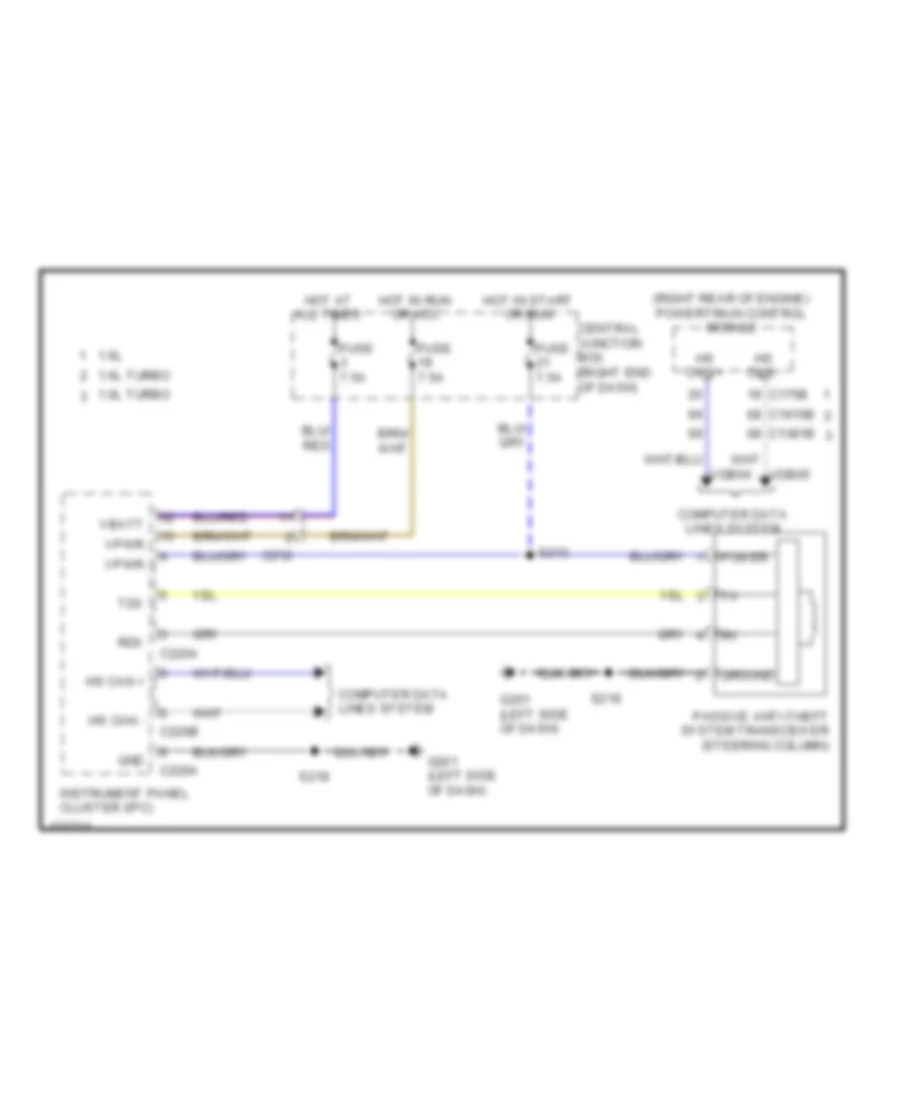
Passive Anti-theft Wiring Diagram, without Keyless Entry for Ford Fiesta S 2014
List of elements for Passive Anti-theft Wiring Diagram, without Keyless Entry for Ford Fiesta S 2014:
- (right rear of engine) powertrain control module
- 1.0l turbo
- 1.6l
- 1.6l turbo
- C1381b
- C175b
- C1915b
- C212
- C220a
- C220b
- Central junction box (right end of dash)
- Computer data lines system
- Fuse 7.5a
- G201 (left side of dash)
- Gnd
- Ground
- Hot at all times
- Hot in run or acc
- Hot in start or run
- Hs can +
- Hs can -
- Instrument panel cluster (ipc)
- Passive anti-theft system transceiver (steering column)
- Power
- Rdx
- S213
- S218
- Tdx
- Vbatt
- Vdb04
- Vdb05
- Vpwr
BODY CONTROL MODULES
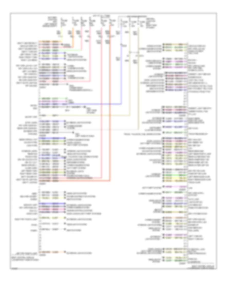
Body Control Modules Wiring Diagram for Ford Fiesta S 2014
List of elements for Body Control Modules Wiring Diagram for Ford Fiesta S 2014:
- (not used)
- Alarm horn
- Ambient light sen rtn
- Ambient light sen sig
- Ambient/moon ltng
- Anti-theft system
- Auto lamp
- Backup lamp
- Batt saver o/p
- Battery junction box (left side of engine compt)
- Body control module (lower right side of dash)
- C210
- C211
- C212
- C2280a
- C2280b
- C2280c
- C2280d
- C2280e
- C2280f
- C2280g
- Cbp11
- Cbp13
- Cbp21
- Cca26
- Cdc30
- Ce436
- Central junction box (right end of dash)
- Cet47
- Chs02
- Chs07
- Chs11
- Chs12
- Chs30
- Chs32
- Clf02
- Clf04
- Clf05
- Clf10
- Clf11
- Clf17
- Clf18
- Clf19
- Clf21
- Clf23
- Clf24
- Clf27
- Cln01
- Cln02
- Cln03
- Cln04
- Cln55
- Cln56
- Cls06
- Cls07
- Cls08
- Cls09
- Cls12
- Cls21
- Cls23
- Cls25
- Cls27
- Cls32
- Cls37
- Cls39
- Cls41
- Cmc28
- Computer data lines system
- Cpl10
- Cpl11
- Cpl13
- Cpl20
- Cpl22
- Cpl25
- Cpl26
- Cpl28
- Cpl29
- Cpl30
- Cpl31
- Cpl36
- Cpl39
- Cpl44
- Cpl51
- Cpl75
- Crd04
- Crd06
- Crd09
- Crh03
- Crh04
- Crt02
- Crw02
- Crw05
- Crw07
- Crw08
- Crw09
- Crw10
- Crw12
- Crw14
- Crw15
- Crw16
- Crw17
- Crw18
- Crw20
- Crw23
- Defogger system
- Delayed accsry
- Dhsrc
- Dimmer down
- Dimmer up
- Door locks & anti-theft systems
- Door locks & anti-theft systems exterior lights system
- Door locks system
- Drv dr unlock mtr
- Drv frt dr ajar
- Drv htd seat telltale
- Drv htd seats sw
- Drv reset sw
- Drv set sw
- Drv unlk sw
- Engine controls system
- Exterior lights system
- Exterior lights system navigation system
- Fflrc
- Flasher sw
- Fog lamps
- Frt sig gnd
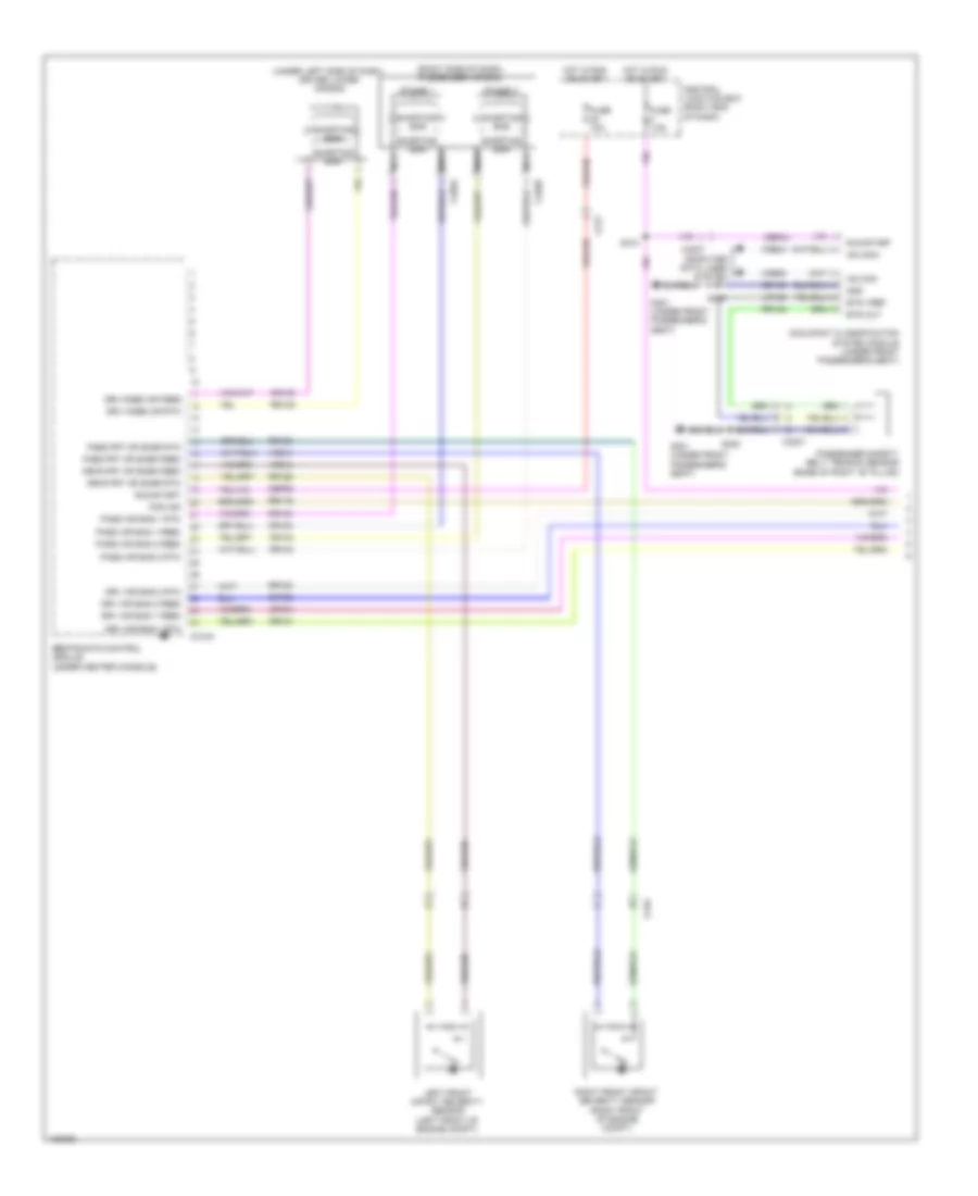
- Frt wpr hi rly o/p
- Frt wpr high sw
- Frt wpr intrvl auto sw
- Frt wpr low rly o/p
- Frt wpr low sw
- Frt wpr park sw
- Frt wpr rtn
- Frt wpr sw gnd frt wpr vrbl interval data
- Frt wpr wshr pmp
- Frt wpr wshr sw
- Fuse 15a
- Fuse 20a
- Fuse 30a
- Fuse 7.5a
- G201 (left side of dash)
- G304 (under front passenger's door sill)
- Gd115
- Gd133
- Gd156
- Gnd
- Hbl rly out
- Hbrc
- Headlights system
- High beam sw
- Hood ajar
- Horns system
- Hot at all times
- Hot in run or start
- Htd backlite button
- Htd backlite telltale
- Ign frt wpr
- Ign rear wpr
- Ign sw
- Instrument cluster system
- Interior lamps
- Interior lights system
- Ip central lock button hzrd warning sw
- Ip illum
- Key-in sw
- Keyless/ign sw ill
- Left front turn
- Left frt postn lamp
- Left low beam
- Left rear door ajar
- Left rear postn lamp
- Left rear turn
- Left turn sw
- Lights off sw
- Lin1
- Lin2
- Lmp07
- Lock mtrs
- Lock telltale
- Low beam sw
- Ms can +
- Ms can -
- Navigation system
- Park sw
- Pass frt dr ajar
- Pass htd seat telltale
- Pass htd seats sw
- Pcm wu
- Phsrc
- Power distribution & interior lights systems
- Power distribution system
- Pwr gnd
- Rear fog
- Rear inner left sn
- Rear inner right sn
- Rear outer left sn
- Rear outer right sn
- Rear sens gnd
- Rear wpr rly o/p
- Rear wpr sply
- Rear wpr wshr sw
- Red
- Right front turn
- Right frt postn lamp
- Right low beam
- Right rear door ajar
- Right rear position lamp rear sens pwr
- Right rear turn
- Right turn sw
- Rlf14
- Rmp07
- Rr wpr intrvl sw
- Rr wpr wshr pmp
- S218
- S239
- Sbb06
- Sbb23
- Sbb25
- Sbb26
- Sbb28
- Sbb34
- Seats system
- Stop lamps
- Trunk ajar
- Trunk mtrs
- Trunk release sw
- Trunk, tailgate, fuel doors system
- Unlock mtrs
- Vbatt extr lighting
- Vbatt heated bklt
- Vbatt locking
- Vbatt saver/horn
- Vbatt turn sig
- Vdb06
- Vdb07
- Vehicle horn o/p
- Vehicle horn sw
- Vlf14
- Vln04
- Vmp14
- Vmp15
- Vmp16
- Vmp17
- Vrt26
- Vrw11
- Vrw26
- Wiper/ washer system
- Wiper/washer system
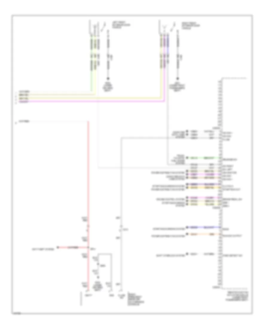
COMPUTER DATA LINES
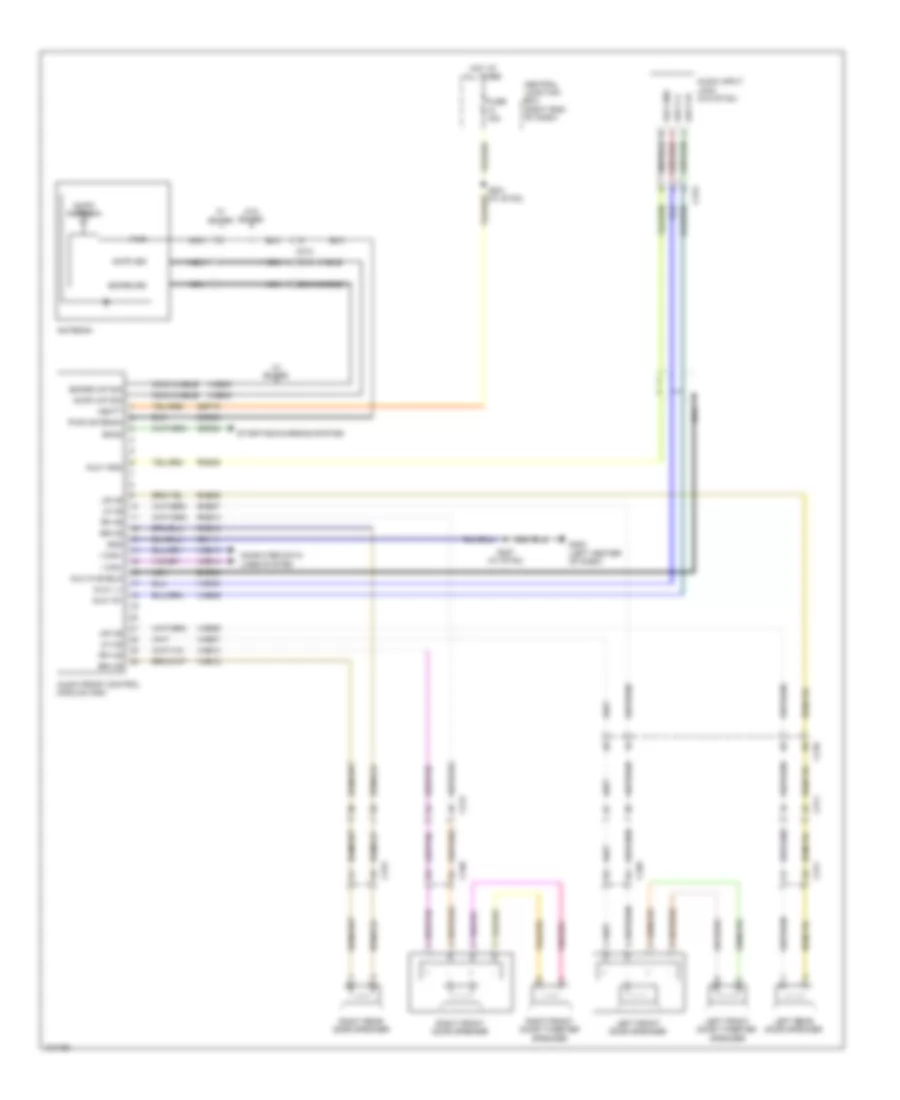
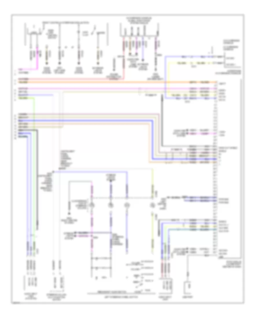
Computer Data Lines Wiring Diagram (1 of 2) for Ford Fiesta S 2014
List of elements for Computer Data Lines Wiring Diagram (1 of 2) for Ford Fiesta S 2014:
- (body main wiring harness, in breakout to c3007) s309
- (body main wiring harness, in breakout to restraints control module) s327
- (engine compt left wiring harness, near breakout to g105) s160
- (instrument panel wiring harness, in breakout to data link connector)
- (instrument panel wiring harness, in breakout to data link connector) s205
- (instrument panel wiring harness, near breakout to g201)
- (instrument panel wiring harness, near breakout to g201) (w/ sync) s211
- (instrument panel wiring harness, near breakout to headlamp switch) s207
- (instrument panel wiring harness, near breakout to headlamp switch) s209
- (left side of dash) g201
- (rear of transmission) (a/t) transmission control module
- 1.0l turbo
- 1.6l
- 1.6l turbo
- Anti-lock brake system control module (right rear corner of engine compt)
- C133
- C1381b
- C140
- C1750a
- C175b
- C1915b
- C210
- C211
- C212
- C214
- C220b
- C2368a
- C3007
- C310b
- Central junction box (right end of dash)
- Data link connector (under left side of dash)
- Fuse 15a
- Gd115
- Hot at all times
- Hs can +
- Hs can -
- Hs can2 +
- Hs can2 -
- I can +
- I can -
- Instrument panel cluster (ipc)
- Ms can +
- Ms can -
- Near breakout to remote function actuator) (w/ keyless entry) s328
- Occupant classification system module (under front passenger's seat)
- Power steering control module (left end of dash)
- Powertrain control module (right rear of engine)
- Restraints control module (under center console)
- S161 (engine compt left wiring harness, near breakout to g105)
- S204
- S206 (instrument panel wiring harness, near breakout to headlamp switch)
- S208 (instrument panel wiring harness, near breakout to headlamp switch)
- S210 (w/ sync)
- S308 (body main wiring harness, in breakout to c3007)
- S329 (w/ keyless entry) (body main wiring harness, near breakout to remote function actuator)
- Sbp05
- Sync
- Vca23
- Vca24
- Vdb04
- Vdb05
- Vdb06
- Vdb07
- Vdb13
- Vdb14
- W/ esp
- W/o esp
Computer Data Lines Wiring Diagram (2 of 2) for Ford Fiesta S 2014
List of elements for Computer Data Lines Wiring Diagram (2 of 2) for Ford Fiesta S 2014:
- (body main wiring harness, near breakout to g304)
- (body main wiring harness, near breakout to g304) s331
- (instrument panel wiring harness, near breakout to g201) s216
- (instrument panel wiring harness, near breakout to g204) s215
- (instrument panel wiring harness, near breakout to g204) s241
- (instrument panel wiring harness, near breakout to passenger airbag) (w/ sync 1) s275
- Audio front control module
- Body control module (lower right side of dash)
- C212
- C214
- C2280e
- C228b
- C240a
- C3503b
- Electronic automatic temperature control module
- Front control/ display interface module
- Front controls interface module
- Global positioning system module (in overhead console)
- Hs can +
- Hs can -
- I can +
- I can -
- I can - ms can +
- I can+
- I can-
- Ms can +
- Ms can -
- Ms can+
- Ms can-
- Remote function actuator module (w/ keyless entry) (under front passenger's seat)
- S234 (instrument panel wiring harness, near breakout to g204)
- S235 (instrument panel wiring harness, near breakout to g204)
- S242 (instrument panel wiring harness, near breakout to g204)
- S274 (w/ sync 1) (instrument panel wiring harness, near breakout to passenger airbag)
- S330
- S910 (interior lamps wiring harness, in breakout to c214)
- S911 (interior lamps wiring harness, in breakout to c214)
- Sync
- Sync 1
- Sync 2
- Sync module (apim) (if equipped) (lower right center of dash)
- Vdb04
- Vdb05
- Vdb06
- Vdb07
- Vdb13
- Vdb13 (or vdb06)
- Vdb14
- Vdb14 (or vdb07)
- W/ sync
COOLING FAN
1.0L TURBO
1.0L Turbo, Cooling Fan Wiring Diagram for Ford Fiesta S 2014
List of elements for 1.0L Turbo, Cooling Fan Wiring Diagram for Ford Fiesta S 2014:
- (engine compt left wiring harness, near breakout to battery junction box) s155
- (engine compt left wiring harness, near breakout to relay box) s111
- Active grille shutter (behind left side of front grille)
- Battery junction box (bjb) (left side of engine compt)
- C1381b
- C1381e
- Caccpc
- Cbp22
- Cdc15
- Ce174
- Cec01
- Cec02
- Central junction box (bjb) (right end of dash)
- Computer data lines system
- Coolant pump (left front of engine compt)
- Cooling fan motor (behind radiator)
- Cooling fan resistor (left front of engine compt)
- Ect
- Engine coolant temperature (ect) sensor (rear of cylinder head)
- Fuse 10a
- Fuse 15a
- Fuse 40a
- Fuse 60a
- Fuse 7.5a
- G102 (right side of transmission housing)
- G109 (left rear of engine compt)
- G113 (left side of engine compt)
- Gd187
- Gnd
- Hfc
- High fan control (hfc) relay
- Hot at all times
- Hot in start or run
- Hot w/ pcm power relay energized
- Hs can+
- Hs can-
- Lfc
- Lin
- Low fan control (lfc) relay
- Powertrain control module (right rear of engine)
- Pwrgnd
- Re141
- S110
- S122
- S163
- S164
- S165
- Sigrtn
- Sp-r
- Vdb04
- Vdb05
- Ve716
- Vpwr
1.6L
1.6L, Cooling Fan Wiring Diagram for Ford Fiesta S 2014
List of elements for 1.6L, Cooling Fan Wiring Diagram for Ford Fiesta S 2014:
- 1.6l
- 1.6l turbo
- Battery junction box (left side of engine compt)
- C175b
- C175e
- C1915b
- C1915e
- Cbp22
- Cec02
- Cec07
- Central junction box (right end of dash)
- Computer data lines system
- Cooling fan module (1.6l turbo) (rear of cooling fan motor)
- Cooling fan motor
- Cooling fan motor (1.6l) (behind radiator)
- Cooling fan relay
- Ect
- Engine coolant temperature (ect) sensor (right rear of cylinder head)
- Fan speed control
- Fcu
- Fuse 10a
- Fuse 40a
- Fuse 7.5a
- G106 (left rear of engine compt)
- G109 (left rear of engine compt)
- G113 (left side of engine compt)
- Gd120
- Gd187
- Gnd
- Hot at all times
- Hot in start or run
- Hot w/ pcm power relay energized
- Hs can+
- Hs can-
- Lfc
- Powertrain control module (right rear of engine)
- Pwgnd
- Pwr
- Re141
- S117
- S122
- S163
- Sigrtn
- Sp-r
- Vdb04
- Vdb05
- Ve230
- Ve716
- W/ air conditioning w/o air conditioning
1.6L TURBO
1.6L Turbo, Cooling Fan Wiring Diagram for Ford Fiesta S 2014
List of elements for 1.6L Turbo, Cooling Fan Wiring Diagram for Ford Fiesta S 2014:
- 1.6l
- 1.6l turbo
- Battery junction box (left side of engine compt)
- C175b
- C175e
- C1915b
- C1915e
- Cbp22
- Cec02
- Cec07
- Central junction box (right end of dash)
- Computer data lines system
- Cooling fan module (1.6l turbo) (rear of cooling fan motor)
- Cooling fan motor
- Cooling fan motor (1.6l) (behind radiator)
- Cooling fan relay
- Ect
- Engine coolant temperature (ect) sensor (right rear of cylinder head)
- Fan speed control
- Fcu
- Fuse 10a
- Fuse 40a
- Fuse 7.5a
- G106 (left rear of engine compt)
- G109 (left rear of engine compt)
- G113 (left side of engine compt)
- Gd120
- Gd187
- Gnd
- Hot at all times
- Hot in start or run
- Hot w/ pcm power relay energized
- Hs can+
- Hs can-
- Lfc
- Powertrain control module (right rear of engine)
- Pwgnd
- Pwr
- Re141
- S117
- S122
- S163
- Sigrtn
- Sp-r
- Vdb04
- Vdb05
- Ve230
- Ve716
- W/ air conditioning w/o air conditioning
CRUISE CONTROL
Cruise Control Wiring Diagram (1 of 2) for Ford Fiesta S 2014
List of elements for Cruise Control Wiring Diagram (1 of 2) for Ford Fiesta S 2014:
- (left rear of engine compt) g106
- (or ve702)
- 1.0l turbo
- 1.6l
- 1.6l turbo
- A/t
- App pwm
- Battery junction box (left side of engine compt)
- Bpp
- C133
- C1381b
- C1381e
- C140
- C1750a
- C1750b
- C175b
- C175e
- C1915b
- C1915e
- C211
- Cbb18
- Cbp22
- Cca26
- Ce414
- Ce415
- Central junction box (cjb) (right end of dash)
- Cet40
- Computer data lines system
- Etcref
- Etcref etcrtn
- Etcrtn
- Except 1.6l
- Exterior lights system
- Fuse 10a
- Fuse 15a
- Fuse 7.5a
- Gd187
- Hot at all times
- Hot in run or start
- Hot w/ pcm power relay energized
- Hs can+
- Hs can-
- Ispr
- Le134
- Le428
- M/t
- Output shaft speed sensor (right rear of transmission)
- P/n sw/ clutch 2
- P/n sw/clutch 2 c175t
- Powertrain control module (right rear of engine)
- Pwr gnd
- Re134
- Re427
- S117
- S122
- S139 (except 1.6l) (engine control wiring harness, near breakout to powertrain control module)
- S140 (except 1.6l) (engine control wiring harness, near breakout to powertrain control module)
- S162
- S202 (engine compt left wiring harness, near breakout to c211)
- S213
- Stoplamp switch (top of brake pedal assembly)
- Tacm+
- Tacm-
- Throttle control unit (1.6l: left rear of engine) (except 1.6l: front of engine)
- Tp1
- Tp2
- Transmission control module (tcm) (rear of transmission)
- Vbatt
- Vdb04
- Vdb05
- Ve701
Cruise Control Wiring Diagram (2 of 2) for Ford Fiesta S 2014
List of elements for Cruise Control Wiring Diagram (2 of 2) for Ford Fiesta S 2014:
- (left rear of engine compt)
- (left side
- 1.0l turbo
- 1.6l & 1.6l turbo
- Accelerator pedal position sensor (top of accelerator pedal assembly)
- App vref2 apps1 pwr
- App2 apps1
- Apps1 rtn app rtn2
- Brk pedal sw
- C210
- C211
- C215
- C218b
- C218c
- C3503b
- Cca29
- Ce903
- Clockspring (top of steering column)
- Clutch pedal cruise control deactivator switch (m/t) (top of brake pedal assembly)
- Clutch pedal position bottom of travel switch (top of clutch pedal assembly)
- Clutch pedal sw
- Computer data lines system
- Cruise control deactivator switch (top of brake pedal assembly)
- Ctrl + res
- Ctrl rtn
- G106
- G106 (left rear of engine compt)
- G201
- Gnd
- Hs can +
- Hs can -
- Instrument panel cluster (ipc)
- Interior lights system
- Of dash)
- Off
- P/n sw/ clutch 2
- Remote function actuator module (w/ intelligent access) (under front passenger's seat)
- Reset/ cancel
- Right steering wheel switch
- S129
- S200
- S203 (engine compt left wiring harness, near breakout to c211)
- S218
- Set (+)
- Set (-)
- Vpwr
DEFOGGERS
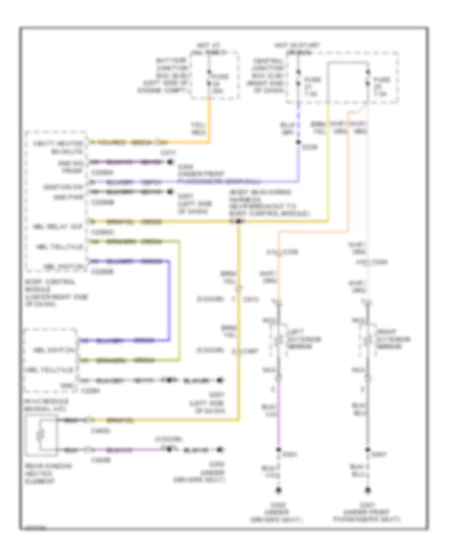
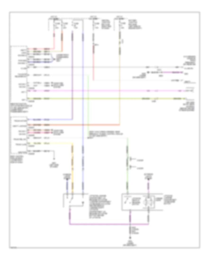
Defoggers Wiring Diagram for Ford Fiesta S 2014
List of elements for Defoggers Wiring Diagram for Ford Fiesta S 2014:
- (5 door)
- (body main wiring harness, near breakout to body control module) s246
- (left side of dash)
- (under driver's seat)
- Battery junction box (bjb) (left side of engine compt)
- Body control module (lower right side of dash)
- C211
- C2280b
- C2280c
- C2280e
- C228a
- C339
- C340
- C402a
- C402b
- C497
- C913
- Cbp21
- Central junction box (cjb) (right end of dash)
- Crd04
- Crd06
- Crd09
- Fuse 20a
- Fuse 7.5a
- G201
- G201 (left side of dash)
- G301 (under front passenger's seat)
- G302
- G302 (under driver's seat)
- G304 (under front passenger's door sill)
- Gd115
- Gd156
- Gnd
- Gnd pwr
- Gnd sig front c2280a
- Hbl relay out
- Hbl switch
- Hbl telltale
- Hot at all times
- Hot in start or run
- Hvac module (manual a/c)
- Ignition sw
- Left exterior mirror
- Nca
- Rear window heated element
- Right exterior mirror
- S218
- S239
- S401
- S501
- S601
- Sbb34
ELECTRONIC POWER STEERING
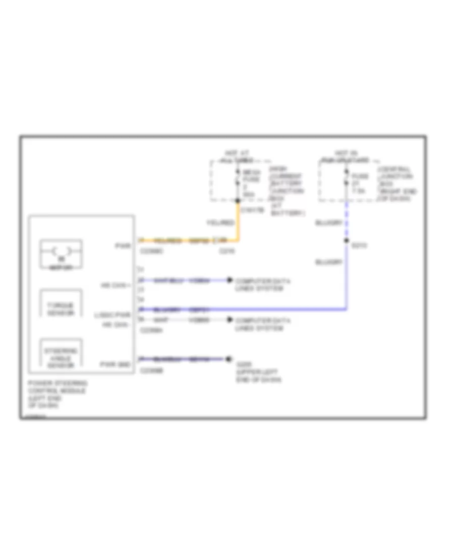
Electronic Power Steering Wiring Diagram for Ford Fiesta S 2014
List of elements for Electronic Power Steering Wiring Diagram for Ford Fiesta S 2014:
- C1617b
- C210
- C2368a
- C2368b
- C2368c
- Cbp21
- Central junction box (right end of dash)
- Computer data lines system
- Fuse 7.5a
- G205 (upper left end of dash)
- Gd114
- High current battery junction box (at battery)
- Hot at all times
- Hot in run or start
- Hs can +
- Hs can -
- Logic pwr
- Mega fuse 60a
- Motor
- Power steering control module (left end of dash)
- Pwr
- Pwr gnd
- S213
- Sbf02
- Steering angle sensor
- Torque sensor
- Vdb04
- Vdb05
ENGINE PERFORMANCE
1.0L TURBO
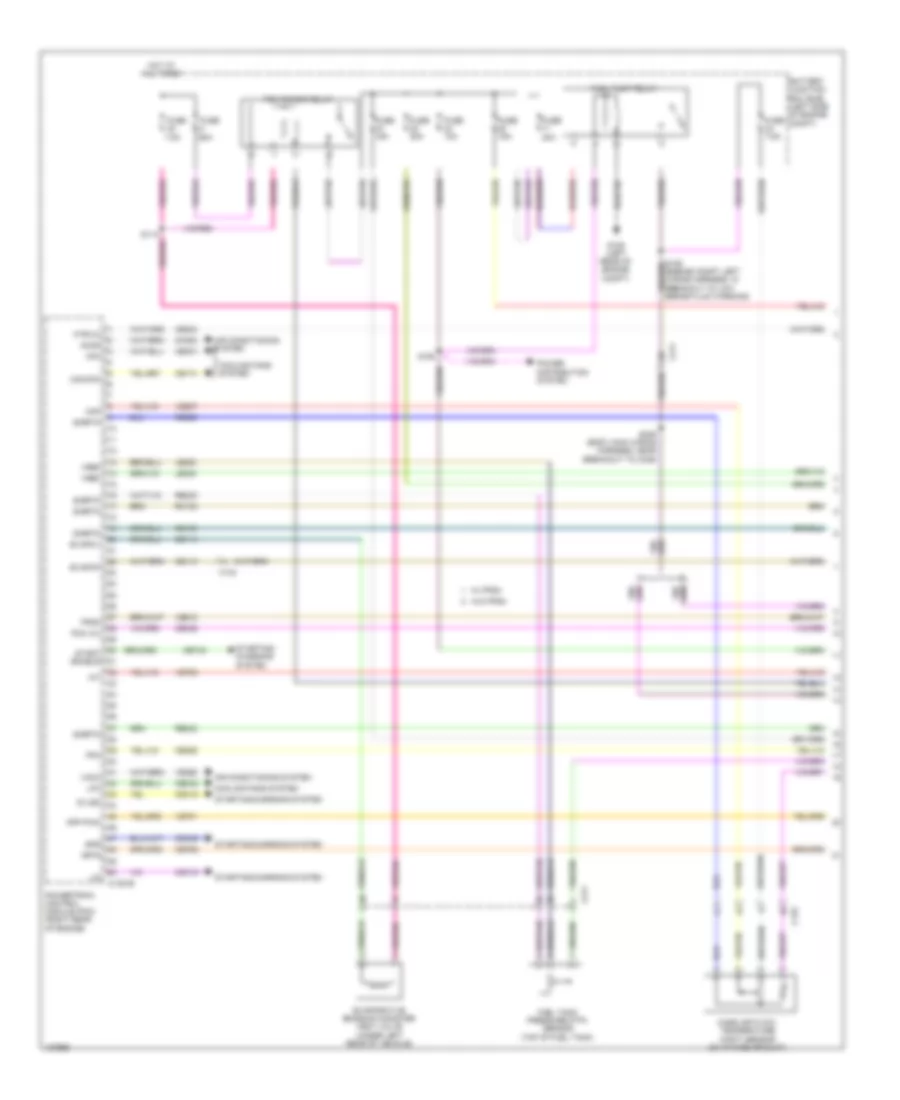
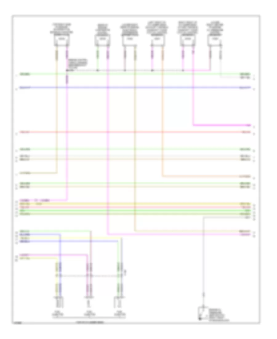
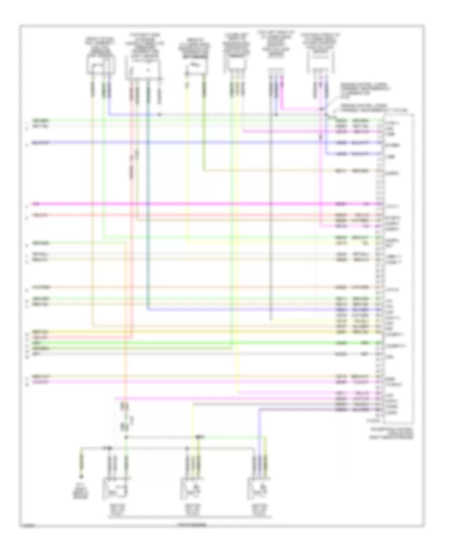
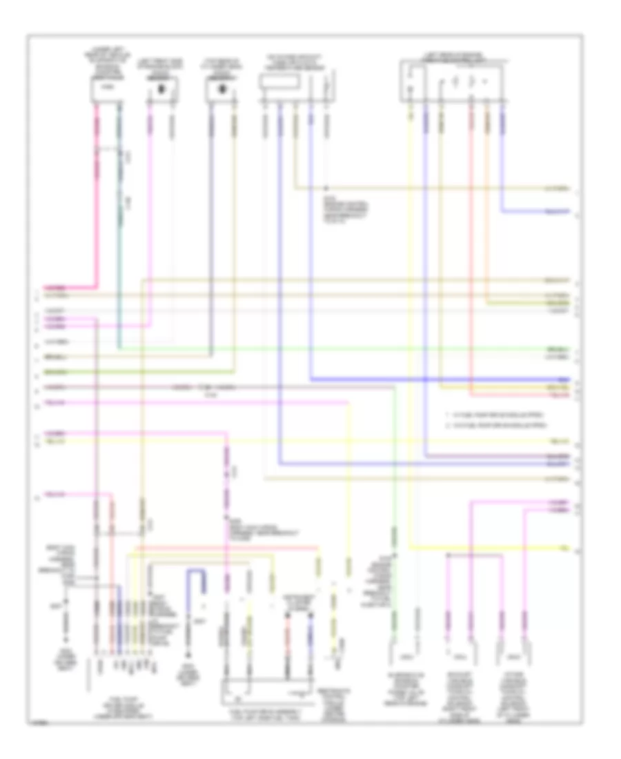
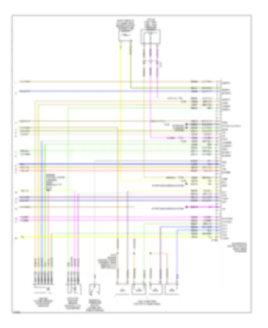
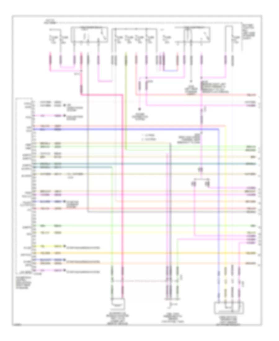
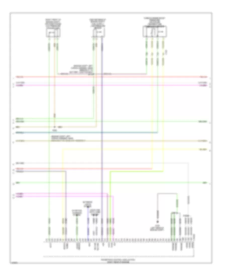
1.0L Turbo, Engine Performance Wiring Diagram (1 of 6) for Ford Fiesta S 2014
List of elements for 1.0L Turbo, Engine Performance Wiring Diagram (1 of 6) for Ford Fiesta S 2014:
- 60a
- 7.5a
- Accr
- Air conditioning system
- App pwm
- Battery junction box (bjb) (left side of engine compt)
- C133
- C1381b
- C211
- Caccpc
- Cbp22
- Cdc12
- Cdc15
- Cdc35
- Ce113
- Ce114
- Ce174
- Ce226
- Ce233
- Ce436
- Cec01
- Cec02
- Cet40
- Ch302
- Cooling fans system
- Evapcp
- Evapcv
- Evaporative emission canister vent valve (under left rear of vehicle)
- Fpc
- Fpdm
- Fuel pump relay
- Fuel tank pressure (ftp) sensor (top of fuel tank)
- Fuse
- Fuse 10a
- Fuse 15a
- Fuse 20a
- Fuse 30a
- Fuse 7.5a
- G109 (left rear of engine compt)
- Hfc
- Hot at all times
- Htr(12)
- Iat
- Isp-r
- Le230
- Le423
- Lfc
- Lin
- Maf
- Mass air flow/ temperature (maft) sensor (on intake air duct)
- Pcm power relay
- Pcm wu
- Power distribution system
- Powertrain control module (pcm) (right rear of engine)
- Re150
- Re230
- Re242
- Re320
- Rh108
- S114
- S163
- S1lsd
- S306 (body main wiring harness, near breakout to c339)
- Sigrtn
- Smr
- Start enable
- Starting/ charging system
- Starting/charging system
- Vacc
- Ve462
- Ve518
- Ve701
- Ve755
- Ve807
- Vref
- W/ fpdm
- W/o fpdm
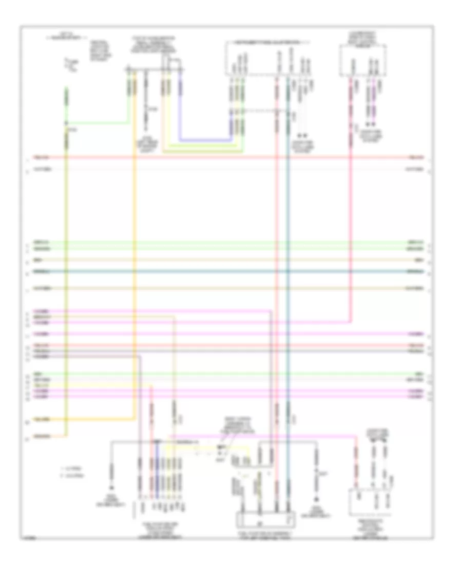
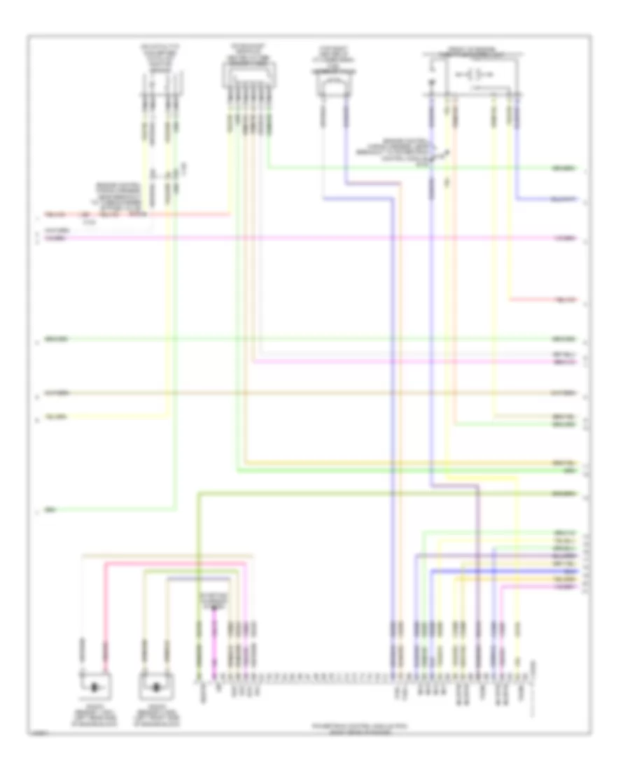
1.0L Turbo, Engine Performance Wiring Diagram (2 of 6) for Ford Fiesta S 2014
List of elements for 1.0L Turbo, Engine Performance Wiring Diagram (2 of 6) for Ford Fiesta S 2014:
- (body wiring harness, in breakout to fuel pump drive)
- (lower right side of dash) body control module
- (top of accelerator pedal assembly) accelerator pedal position (app) sensor
- App rtn2
- App vref2
- App2
- C210
- C211
- C220a
- C220b
- C2280d
- C2280e
- C310b
- Ce226
- Ce436
- Ce515
- Ce608
- Central junction box (cjb) (right end of dash)
- Computer data lines system
- Cr167
- Ens
- Fpc
- Fpm
- Fuel lvl i/p
- Fuel lvl rtn
- Fuel pump drive assembly (top left side fuel tank)
- Fuel pump driver module (fpdm) (if equipped) (under driver's seat)
- Fuse 7.5a
- G106 (left rear of engine compt)
- G303 (under driver's seat)
- Gd354
- Gnd
- Hot in run or start
- Hs can +
- Hs can -
- Instrument panel cluster (ipc)
- Ms can +
- Ms can -
- Mtr+
- Mtr-
- Nca
- Pcm wu
- Re515
- Restraints control module (rcm) (under center console)
- S122
- S129
- S307
- S406
- S407
- Vdb04
- Vdb05
- Vdb06
- Vdb07
- Ve518
- Vpwr
- W/ fpdm
- W/o fpdm
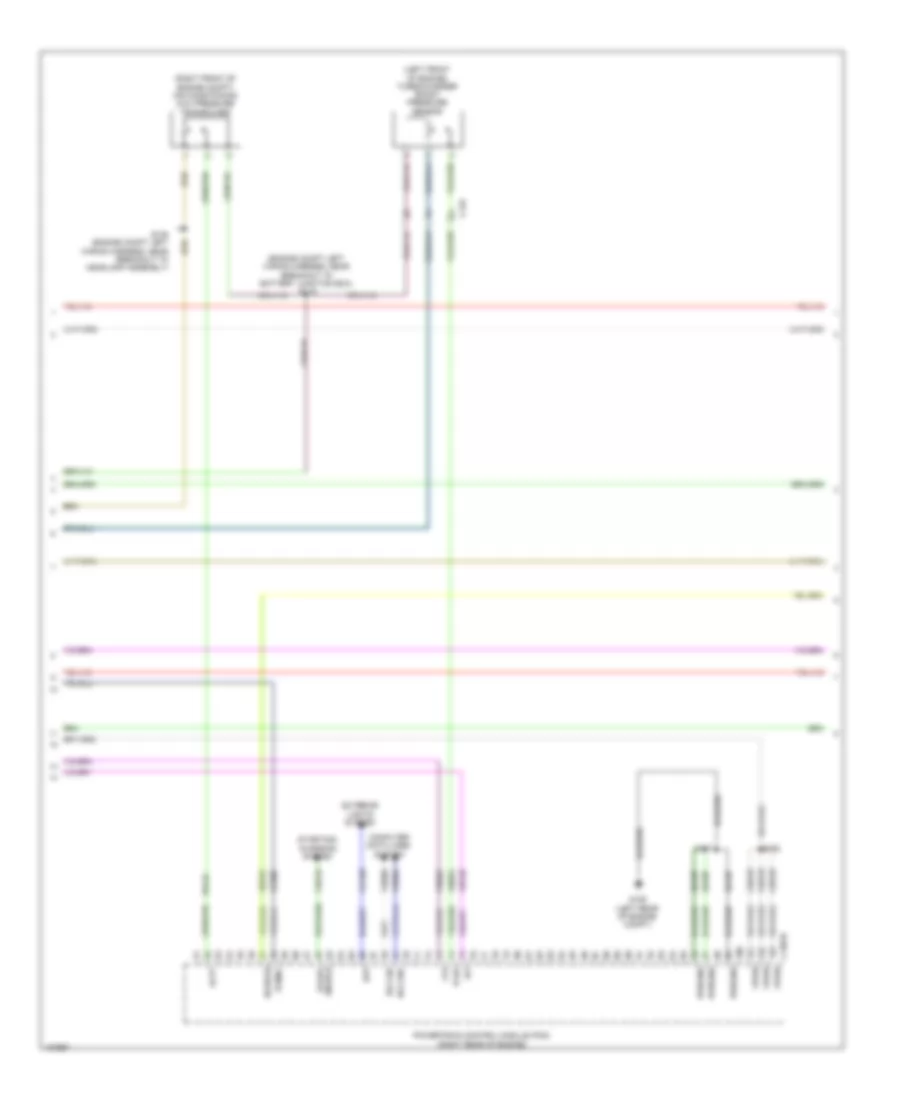
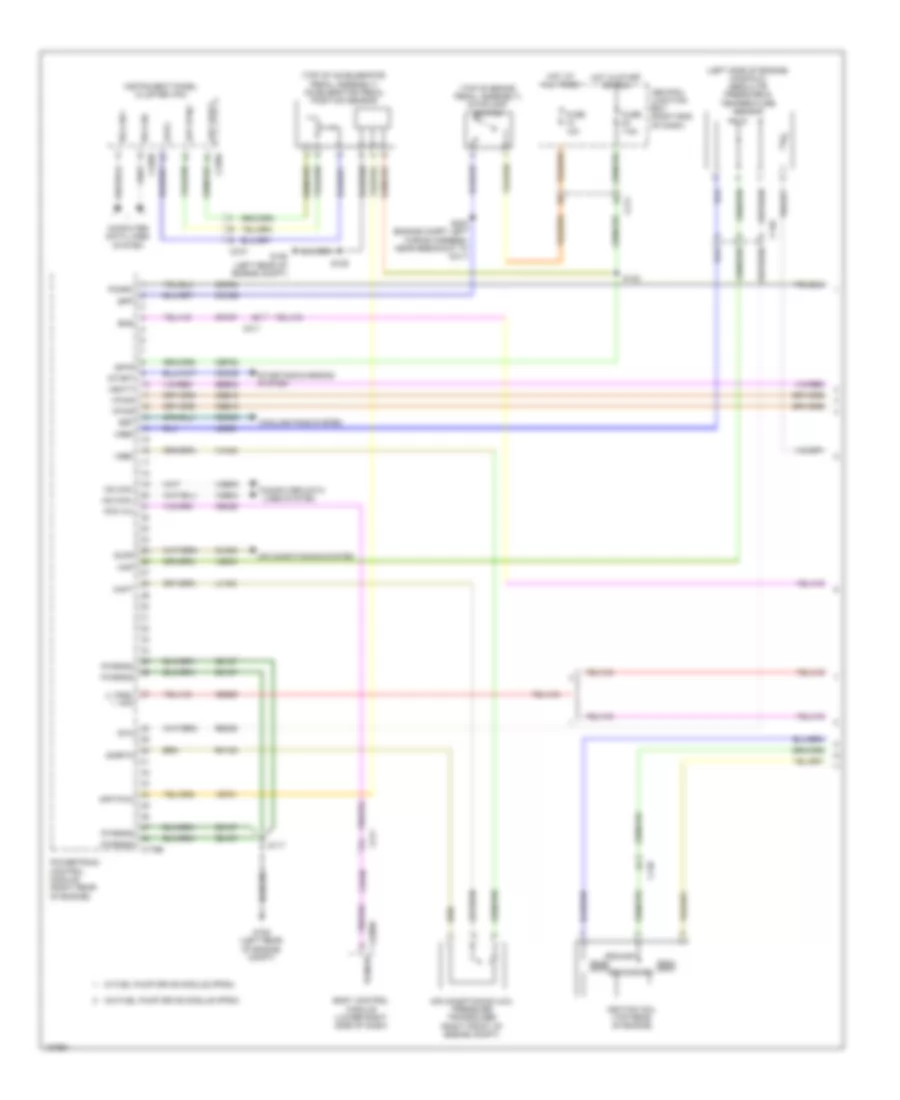
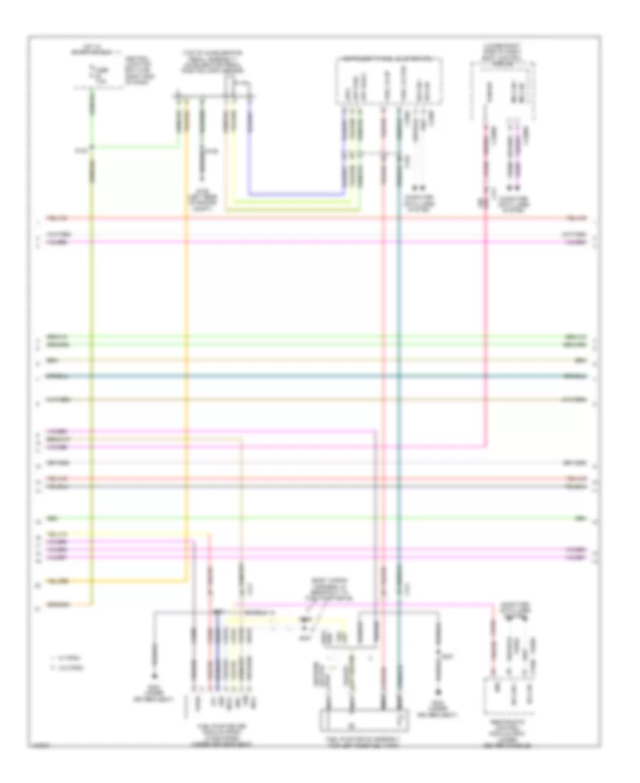
1.0L Turbo, Engine Performance Wiring Diagram (3 of 6) for Ford Fiesta S 2014
List of elements for 1.0L Turbo, Engine Performance Wiring Diagram (3 of 6) for Ford Fiesta S 2014:
- (engine compt left wiring harness, near breakout to battery junction box) s115
- (left front of engine) turbocharger boost pressure sensor
- (right front of engine compt) air conditioning (a/c) pressure transducer
- Acpt
- Bpp
- C133
- C1381b
- Cbb18
- Cca26
- Cdc54
- Ce302
- Computer data lines system
- Enable
- Exterior lights system
- Ftp
- G106 (left rear of engine compt)
- Gd187
- Ho2s(12)
- Hs can+
- Hs can-
- Iat
- Pcmrc
- Powertrain control module (pcm) (right rear of engine)
- Pwrgnd
- S117
- S135 (engine compt left wiring harness, near breakout to headlamp assembly)
- S162
- Start
- Starting/ charging system
- Tcbp
- Vdb04
- Vdb05
- Ve731
- Ve740
- Ve824
- Ve922
- Vh442
- Vpwr
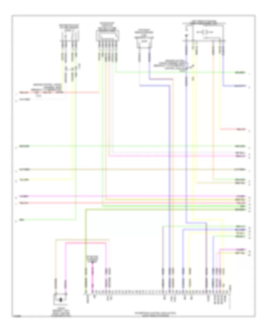
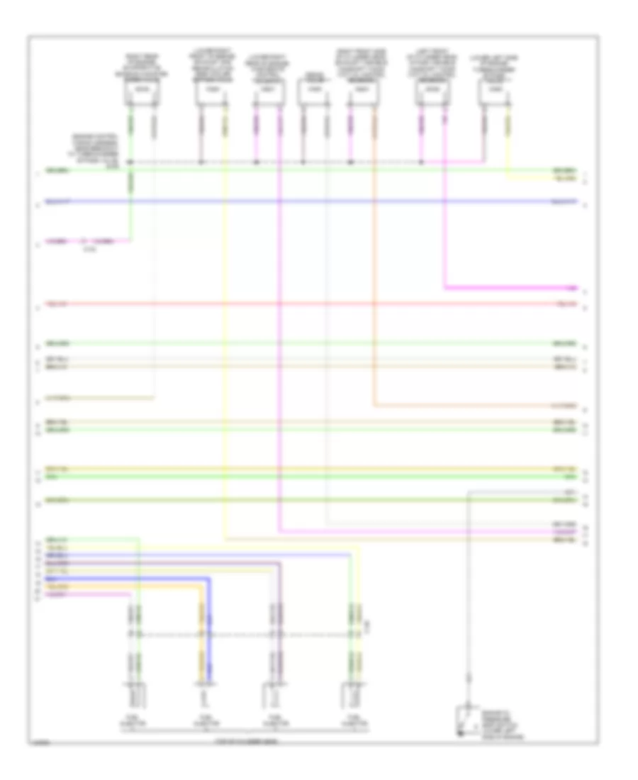
1.0L Turbo, Engine Performance Wiring Diagram (4 of 6) for Ford Fiesta S 2014
List of elements for 1.0L Turbo, Engine Performance Wiring Diagram (4 of 6) for Ford Fiesta S 2014:
- (engine control wiring harness, near breakout to generator) s103
- (engine control wiring harness, near breakout to powertrain control module) s140
- (left rear of engine) throttle control unit
- (on exhaust manifold) heated oxygen sensor (ho2s)
- (top right rear of engine) fuel metering valve
- C133
- C1381e
- Cdc15
- Ce205
- Ce206
- Ce207
- Ce256
- Fvrc+
- Fvrc-
- Heated exhaust oxygen sensor (h02s) 12
- Inj1
- Inj1rtn
- Inj2
- Inj2rtn
- Inj3
- Inj3rtn
- Knock sensor 1 (ks1) (right center of engine block)
- Ks1+
- Ks1-
- Le134
- Lin
- Nca
- Powertrain control module (pcm) (right rear of engine)
- Re134
- Re135
- Re205
- Re206
- Re207
- Re256
- Re323
- S139
- Sigrtn
- Starting/ charging system
- Tacm+
- Tacm-
- Ve801
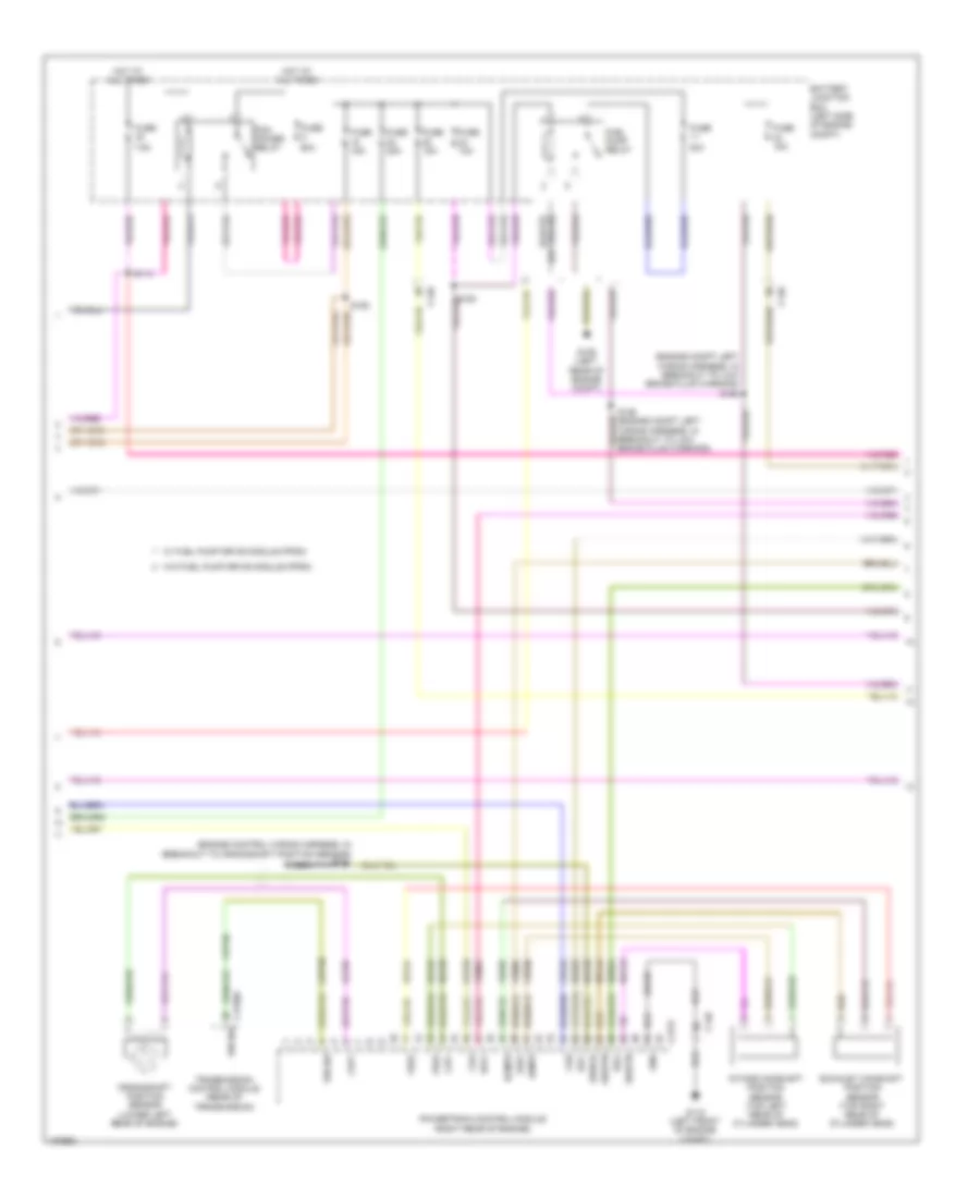
1.0L Turbo, Engine Performance Wiring Diagram (5 of 6) for Ford Fiesta S 2014
List of elements for 1.0L Turbo, Engine Performance Wiring Diagram (5 of 6) for Ford Fiesta S 2014:
- (engine control wiring harness, near breakout to c146) s109
- (left front of cylinder head) exhaust variable camshaft timing (vct) oil control solenoid
- (lower right center of engine) oil pressure control solenoid
- (lower right rear of engine) electronic compressor bypass valve
- (rear of engine) wastegate control solenoid
- (right front of cylinder head) intake variable camshaft timing (vct) oil control solenoid
- (top of cylinder head)
- (top right side of engine) evaporative emission canister purge valve
- C133
- C146
- Engine oil pressure (eop) switch (right front of engine block)
- Fuel injector
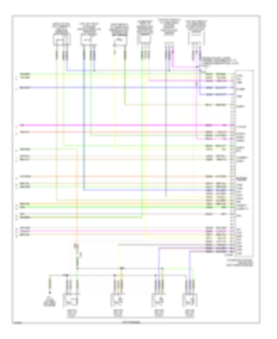
1.0L Turbo, Engine Performance Wiring Diagram (6 of 6) for Ford Fiesta S 2014
List of elements for 1.0L Turbo, Engine Performance Wiring Diagram (6 of 6) for Ford Fiesta S 2014:
- (engine control wiring harness, near breakout to c146)
- (engine control wiring harness, near breakout to generator) s145
- (front of fuel rail assembly) fuel rail pressure (frp) sensor
- (lower left front of engine block) crankshaft position (ckp) sensor
- (rear of cylinder head) engine coolant temperature (ect) sensor
- (top left front of cylinder head) exhaust camshaft position (cmp) sensor
- (top of engine)
- (top right front of cylinder head) intake camshaft position (cmp) sensor
- (top right side of engine) manifold absolute pressure/ temperature (mapt) sensor
- C133
- C1381e
- Ce235
- Ce303
- Ce304
- Ce305
- Ce358
- Ce414
- Ce415
- Ce421
- Ce422
- Ce460
- Ckp
- Cmc24
- Cmp
- Cmp (11)
- Cop1a
- Cop2b
- Cop3c
- Ecbv
- Ect
- Etcref
- Etcrtn
- Frp
- G111 (right rear of engine)
- Htr(11)
- Ignition coil on plug 1
- Ignition coil on plug 2
- Ignition coil on plug 3
- Le135
- Le428
- Le448
- Le451
- Le452
- Le458
- Map
- Ops
- Powertrain control module (pcm) (right rear of engine)
- Re141
- Re143
- Re329
- Re405
- Re427
- S108
- S142
- S143
- Sigrtn
- Tcwrvs
- Tp1
- Tp2
- Uo2s(11)
- Uo2spc11
- Uo2spct11
- Uref(11)
- Vct(11)
- Vct(12)
- Ve175
- Ve711
- Ve716
- Ve727
- Ve736
- Ve738
- Ve803
- Ve826
- Vref
1.6L
1.6L, Engine Performance Wiring Diagram (1 of 4) for Ford Fiesta S 2014
List of elements for 1.6L, Engine Performance Wiring Diagram (1 of 4) for Ford Fiesta S 2014:
- (left side of engine) manifold absolute pressure & temperature sensor
- (top of accelerator pedal assembly) accelerator pedal position sensor
- (top of brake pedal assembly) stoplamp switch
- Accr
- Acpt
- Air conditioning (a/c) pressure transducer (right front of engine compt)
- Air conditioning system
- App pwm
- App rtn2
- App vref2
- App2
- Body control module (lower right side of dash)
- Bpp
- C140
- C175b
- C210
- C211
- C220a
- C220b
- C2280d
- Cbb18
- Cbp22
- Cca26
- Cdc35
- Ce226
- Ce302
- Ce436
- Cec02
- Central junction box (right end of dash)
- Ch302
- Computer data lines system
- Cooling fans system
- Cr167
- Edf
- Ens
- Fprc fpc
- Fuse 10a
- Fuse 7.5a
- G106 (left rear of engine compt)
- Gd187
- Hot at all times
- Hot in start or run
- Hs can +
- Hs can -
- Hs can+
- Hs can-
- Ignition coil (top rear of engine)
- Instrument panel cluster (ipc)
- Isp-r
- Le329
- Lh108
- Map
- Pcm wu
- Pcmrc
- Powertrain control module (right rear of engine)
- Primary
- Pwrgnd
- Re329
- Rh108
- Rtn
- S117
- S122
- S129
- S202 (engine compt left wiring harness, near breakout to c211)
- Sbb32
- Secondary
- Sigrtn
- Start
- Starting/charging system
- Vbatt
- Vdb04
- Vdb05
- Ve701
- Ve804
- Vh442
- Vpwr
- Vref
- W/ fuel pump drive module (fpdm)
- W/o fuel pump drive module (fpdm)
1.6L, Engine Performance Wiring Diagram (2 of 4) for Ford Fiesta S 2014
List of elements for 1.6L, Engine Performance Wiring Diagram (2 of 4) for Ford Fiesta S 2014:
- (engine compt left wiring harness, in breakout to low brake fluid warning) s126
- (engine control wiring harness, in breakout to crankshaft position sensor) s101
- 30a
- 60a
- 7.5a
- Battery junction box (left side of engine compt)
- C140
- C1750a
- C175t
- Cda
- Cdb
- Ce123
- Ce124
- Cet40
- Ckp+
- Ckp-
- Crankshaft position sensor (lower left rear of engine)
- De135
- Ecmps
- Exhaust camshaft position sensor (top right rear of cylinder head)
- Fuel pump relay
- Fuse
- Fuse 10a
- Fuse 15a
- Fuse 20a
- G109 (left rear of engine compt)
- G115 (left front of engine compt)
- Gd122
- Gnd
- Hot at all times
- Icmps
- Intake camshaft position sensor (top left rear of cylinder head)
- Ks1+
- Ks1-
- Ks2+
- Ks2-
- Le135
- Le143
- Le144
- Nca
- P/n sw
- Pcm power relay
- Powertrain control module (right rear of engine)
- Re135
- Re143
- Re144
- Re323
- Re324
- S114
- S126 (engine compt left wiring harness, in breakout to low brake fluid warning)
- S162
- Shield
- Sigrtn
- Transmission control module (rear of transmission)
- Ve706
- Ve707
- Ve801
- Ve802
- Vref
- W/ fuel pump drive module (fpdm)
- W/o fuel pump drive module (fpdm)
1.6L, Engine Performance Wiring Diagram (3 of 4) for Ford Fiesta S 2014
List of elements for 1.6L, Engine Performance Wiring Diagram (3 of 4) for Ford Fiesta S 2014:
- (body main wiring harness, near breakout to c339) s306
- (left front side of engine block) knock sensor 1
- (left rear of engine) throttle control unit
- (on intake air duct) mass air flow & temperature sensor
- (top rear of cylinder head) knock sensor 2
- (under left rear of vehicle) evaporative emission canister vent valve
- C140
- C211
- C310b
- Ce226
- Ce515
- Ce608
- Cr167
- Ens
- Evaporative emission canister purge valve (top left rear of engine)
- Exhaust variable camshaft timing oil control solenoid (right front side of cylinder head)
- Fpc
- Fpm
- Fuel pump drive assembly (top left side fuel tank)
- Fuel pump driver module (if equipped) (under driver's seat)
- G303 (under driver's seat)
- Gd354
- Gnd
- Instrument cluster system
- Intake variable camshaft timing oil control solenoid (left front of cylinder head)
- Mtr +
- Mtr -
- Nca
- Restraints control module (under center console)
- S103 (engine control wiring harness, near breakout to g114)
- S109 (engine control wiring harness, near breakout to fuel injector 2)
- S306 (body main wiring harness, near breakout to c339)
- S307
- Ve518
- Vpwr
- W/ fuel pump drive module (fpdm)
- W/o fuel pump drive module (fpdm)
1.6L, Engine Performance Wiring Diagram (4 of 4) for Ford Fiesta S 2014
List of elements for 1.6L, Engine Performance Wiring Diagram (4 of 4) for Ford Fiesta S 2014:
- (engine control wiring harness, near breakout to g114) s103
- (right rear of cylinder head) engine coolant temperature sensor
- (top of fuel tank) fuel tank pressure sensor
- C140
- C175e
- C211
- Catalyst monitor sensor (on catalytic converter)
- Cdc12
- Cdc15
- Cdc54
- Ce113
- Ce114
- Ce233
- Ce235
- Ce414
- Ce415
- Ce444
- Ce446
- Ce903
- Cmc24
- Cms +
- Engine oil pressure switch (lower left side of engine)
- Etc
- Etcref
- Etcrtn
- Evapcp
- Evapcv
- Evctocs
- Fpdm
- Ftpt
- Fuel injectors (top of cylinder head)
- Heated oxygen sensor (on exhaust manifold)
- Htr
- Iat
- Inj 1
- Inj 2
- Inj 3
- Inj 4
- Ivctocs
- Le134
- Le230
- Le329
- Le428
- Le448
- Le451
- Le452
- Lin
- Maf
- Nca
- Ops
- P/n sw clutch 2
- Powertrain control module (right rear of engine)
- Re134
- Re141
- Re145
- Re205
- Re206
- Re207
- Re208
- Re230
- Re242
- Re329
- Re427
- Re433
- S133 (engine control wiring harness, near breakout to ignition coil)
- Sigrtn
- Sirc
- Smcs
- Starting/ charging system
- Starting/charging system
- Tacm+
- Tacm-
- Tp1
- Tp2
- Uo2s
- Uo2spc
- Uo2spct
- Uo2sref
- Ve518
- Ve716
- Ve740
- Ve826
- Ve922
- Vref
1.6L TURBO
1.6L Turbo, Engine Performance Wiring Diagram (1 of 6) for Ford Fiesta S 2014
List of elements for 1.6L Turbo, Engine Performance Wiring Diagram (1 of 6) for Ford Fiesta S 2014:
- 60a
- 7.5a
- Accr
- Air conditioning system
- App pwm
- Battery junction box (left side of engine compt)
- C133
- C1915b
- C211
- Cbp22
- Cdc12
- Cdc15
- Cdc35
- Ce113
- Ce114
- Ce226
- Ce233
- Ce436
- Ce903
- Ch302
- Cooling fans system
- Evapcp
- Evapcv
- Evaporative emission canister vent valve (under left rear of vehicle)
- Fpc
- Fpdm
- Fuel pump relay
- Fuel tank pressure (ftp) sensor (top of fuel tank)
- Fuse
- Fuse 10a
- Fuse 15a
- Fuse 20a
- Fuse 30a
- Fuse 7.5a
- G109 (left rear of engine compt)
- Hot at all times
- Htr12
- Iat
- Isp-r
- Le230
- Le423
- Lin1 (bms)
- Maf
- Mass air flow/ temperature (maft) sensor (on intake air duct)
- P/n sw clutch 2
- Pcm power relay
- Pcm wu
- Power distribution system
- Powertrain control module (pcm) (right rear of engine)
- Pwm
- Re150
- Re230
- Re242
- Re320
- Rh108
- Rtn
- S114
- S1hsd
- S1lsd
- S306 (body main wiring harness, near breakout to c339)
- Sigrtn
- Starting/ charging system
- Starting/charging system
- Ve230
- Ve518
- Ve701
- Ve755
- Ve807
- Vref
- W/ fpdm
- W/o fpdm
1.6L Turbo, Engine Performance Wiring Diagram (2 of 6) for Ford Fiesta S 2014
List of elements for 1.6L Turbo, Engine Performance Wiring Diagram (2 of 6) for Ford Fiesta S 2014:
- (body wiring harness, in breakout to fuel pump drive)
- (lower right side of dash) body control module
- (top of accelerator pedal assembly) accelerator pedal position (app) sensor
- App rtn2
- App vref2
- App2
- C210
- C211
- C220a
- C220b
- C2280d
- C2280e
- C310b
- Ce226
- Ce436
- Ce515
- Ce608
- Central junction box (cjb) (right end of dash)
- Computer data lines system
- Cr167
- Ens
- Fpc
- Fpm
- Fuel lvl i/p
- Fuel lvl rtn
- Fuel pump drive assembly (top left side fuel tank)
- Fuel pump driver module (fpdm) (if equipped) (under driver's seat)
- Fuse 7.5a
- G106 (left rear of engine compt)
- G303 (under driver's seat)
- Gd354
- Gnd
- Hot in start or run
- Hs can +
- Hs can -
- Instrument panel cluster (ipc)
- Ms can +
- Ms can -
- Mtr+
- Mtr-
- Nca
- Pcm wu
- Re515
- Restraints control module (rcm) (under center console)
- S122
- S307
- S406
- S407
- Vdb04
- Vdb05
- Vdb06
- Vdb07
- Ve518
- Vpwr
- W/ fpdm
- W/o fpdm
1.6L Turbo, Engine Performance Wiring Diagram (3 of 6) for Ford Fiesta S 2014
List of elements for 1.6L Turbo, Engine Performance Wiring Diagram (3 of 6) for Ford Fiesta S 2014:
- (engine compt left wiring harness, near breakout to battery junction box) s115
- (engine compt left wiring harness, near breakout to headlamp assembly)
- (right front of engine compt) air conditioning (a/c) pressure transducer
- Acpt
- Bpp
- C133
- C1915b
- Cbb18
- Cca26
- Cdc54
- Ce302
- Computer data lines system
- Enable
- Exterior lights system
- Frp
- Ftpt
- G106 (left rear of engine compt)
- Gd187
- Ho2s12
- Hs can+
- Hs can-
- Iat
- Pcmrc
- Powertrain control module (pcm) (right rear of engine)
- Pwrgnd
- S117
- S135
- S162
- Start
- Starting/ charging system
- Tcbp
- Turbocharger boost pressure/ air cooler temperature (tcbp/cact) sensor
- Vdb04
- Vdb05
- Ve731
- Ve740
- Ve761
- Ve824
- Ve922
- Vh442
- Vpwr
1.6L Turbo, Engine Performance Wiring Diagram (4 of 6) for Ford Fiesta S 2014
List of elements for 1.6L Turbo, Engine Performance Wiring Diagram (4 of 6) for Ford Fiesta S 2014:
- (engine control wiring harness, near breakout to powertrain control module) s140
- (engine control wiring harness, near breakout to turbocharger bypass valve) s103
- (front of engine) throttle control unit
- (on catalytic converter) catalyst monitor sensor
- (on exhaust manifold) heated oxygen sensor (ho2s)
- (top right center of cylinder bank) fuel metering valve
- C133
- C1915e
- Cdc15
- Ce205
- Ce206
- Ce207
- Ce208
- Ce256
- Fvrc+
- Fvrc-
- Inj1
- Inj1rtn
- Inj2
- Inj2rtn
- Inj3
- Inj3rtn
- Inj4
- Inj4rtn
- Knock sensor 1 (ks1) (left rear side of engine block)
- Knock sensor 2 (ks2) (left front side of engine block)
- Ks1+
- Ks1-
- Ks2+
- Ks2-
- Le134
- Lin
- Nca
- Powertrain control module (pcm) (right rear of engine)
- Re134
- Re135
- Re205
- Re206
- Re207
- Re208
- Re256
- Re323
- Re324
- S139
- Sigrtn
- Starting/ charging system
- Tacm+
- Tacm-
- Ve801
- Ve802
1.6L Turbo, Engine Performance Wiring Diagram (5 of 6) for Ford Fiesta S 2014
List of elements for 1.6L Turbo, Engine Performance Wiring Diagram (5 of 6) for Ford Fiesta S 2014:
- (engine control wiring harness, near breakout to turbocharger bypass valve) s109
- (left front of cylinder head) intake variable camshaft timing (vct) oil control solenoid
- (lower left side of engine) turbocharger bypass valve
- (lower right front of engine) exhaust gas recirculation (egr) cooler bypass valve
- (lower right rear of engine) wastegate control solenoid
- (right front side of cylinder head) exhaust variable camshaft timing (vct) oil control solenoid
- (right rear of engine) evaporative emission canister purge valve
- (top of cylinder head)
- C110
- C133
- Degas valve
- Engine oil pressure (eop) switch (lower left side of engine)
- Fuel injector
1.6L Turbo, Engine Performance Wiring Diagram (6 of 6) for Ford Fiesta S 2014
List of elements for 1.6L Turbo, Engine Performance Wiring Diagram (6 of 6) for Ford Fiesta S 2014:
- (engine control wiring harness, near breakout to turbocharger bypass valve) s145
- (front of fuel rail assembly) fuel rail pressure (frp) sensor
- (lower right front of engine block) crankshaft position (ckp) sensor
- (right rear of cylinder head) engine coolant temperature (ect) sensor
- (top left front of engine) manifold absolute pressure (map) sensor
- (top left rear of cylinder head) intake camshaft position (cmp) sensor
- (top of engine)
- (top right rear of cylinder head) exhaust camshaft position (cmp) sensor
- C133
- C1915e
- Cdv
- Ce166
- Ce167
- Ce235
- Ce303
- Ce304
- Ce305
- Ce306
- Ce414
- Ce415
- Ce421
- Ce422
- Ce460
- Ckp
- Cmc24
- Cmp11
- Cmp12
- Cop1
- Cop2
- Cop3
- Cop4
- Ecbv
- Etc
- Etcref
- Etcrtn
- Evctocs tss/oss/
- Frp
- G111 (lower left rear of engine)
- Htr11
- Ignition coil on plug 1
- Ignition coil on plug 2
- Ignition coil on plug 3
- Ignition coil on plug 4
- Ivctocs
- Le135
- Le428
- Le448
- Le451
- Le452
- Le458
- Map
- Ops
- Powertrain control module (pcm) (right rear of engine)
- Re141
- Re143
- Re329
- Re405
- Re427
- S108
- S142
- S143
- Sigrtn
- Tbv
- Tpng
- Tpps
- Uo2s11
- Uo2spc11
- Uo2spct11
- Uo2sref11
- Ve711
- Ve716
- Ve727
- Ve736
- Ve738
- Ve803
- Ve826
- Ve917
- Vref
- Wcs
EXTERIOR LIGHTS
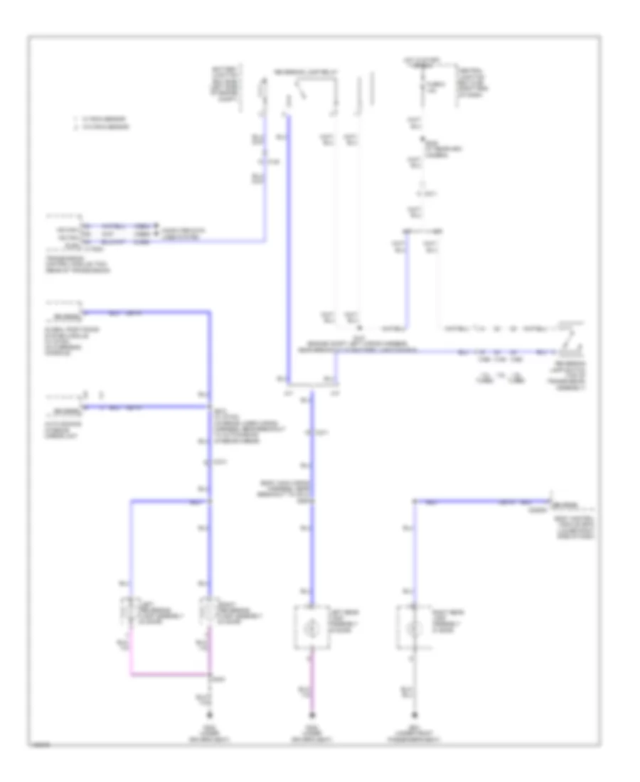
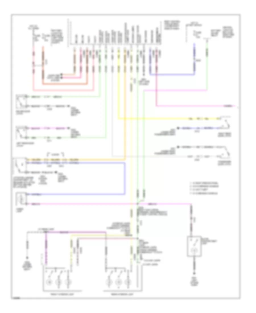
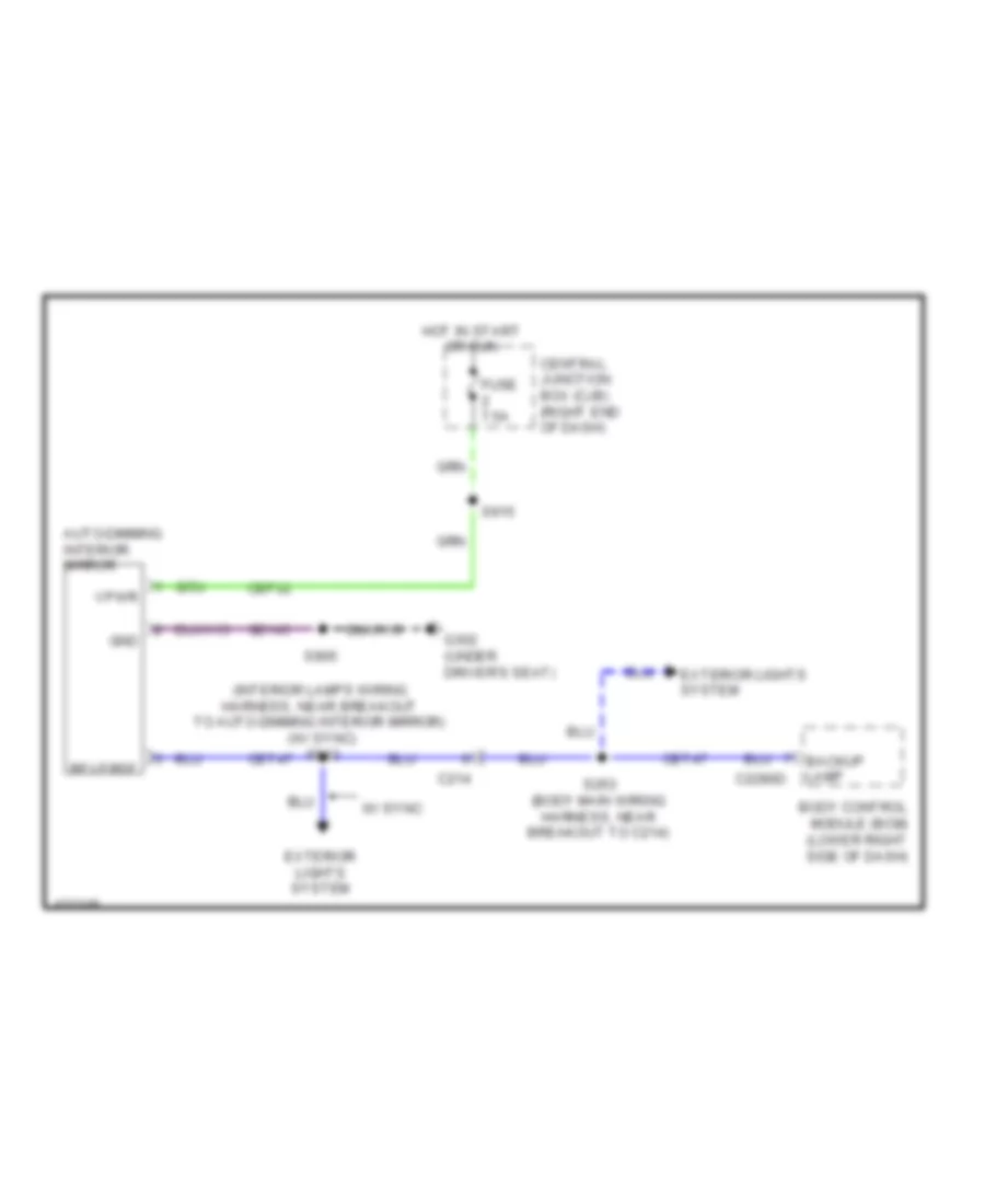
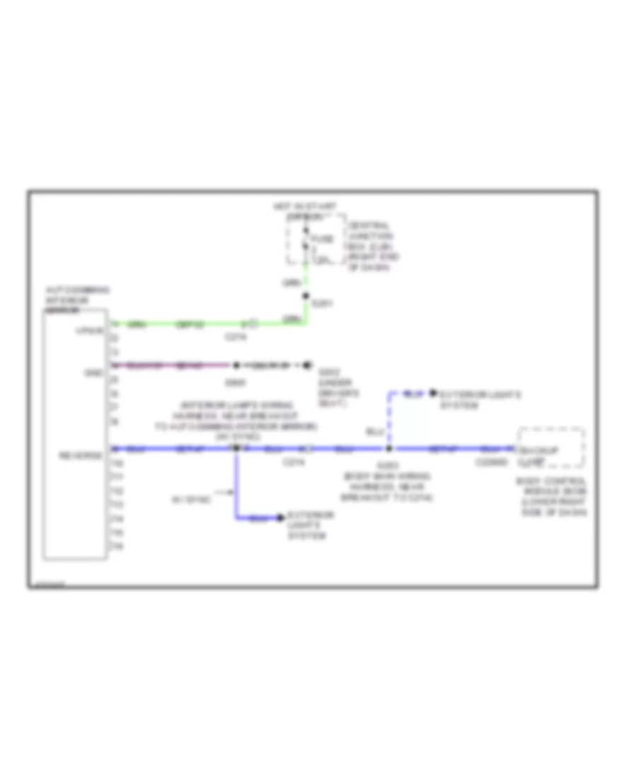
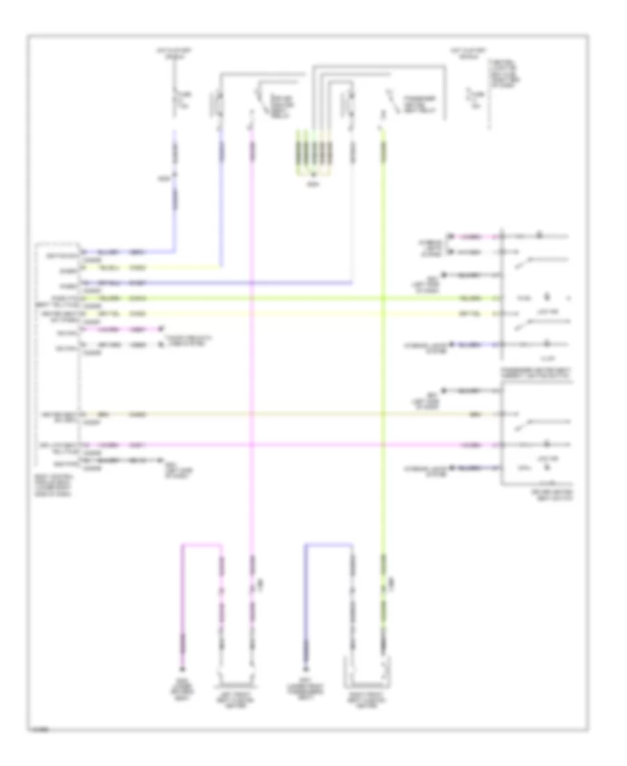
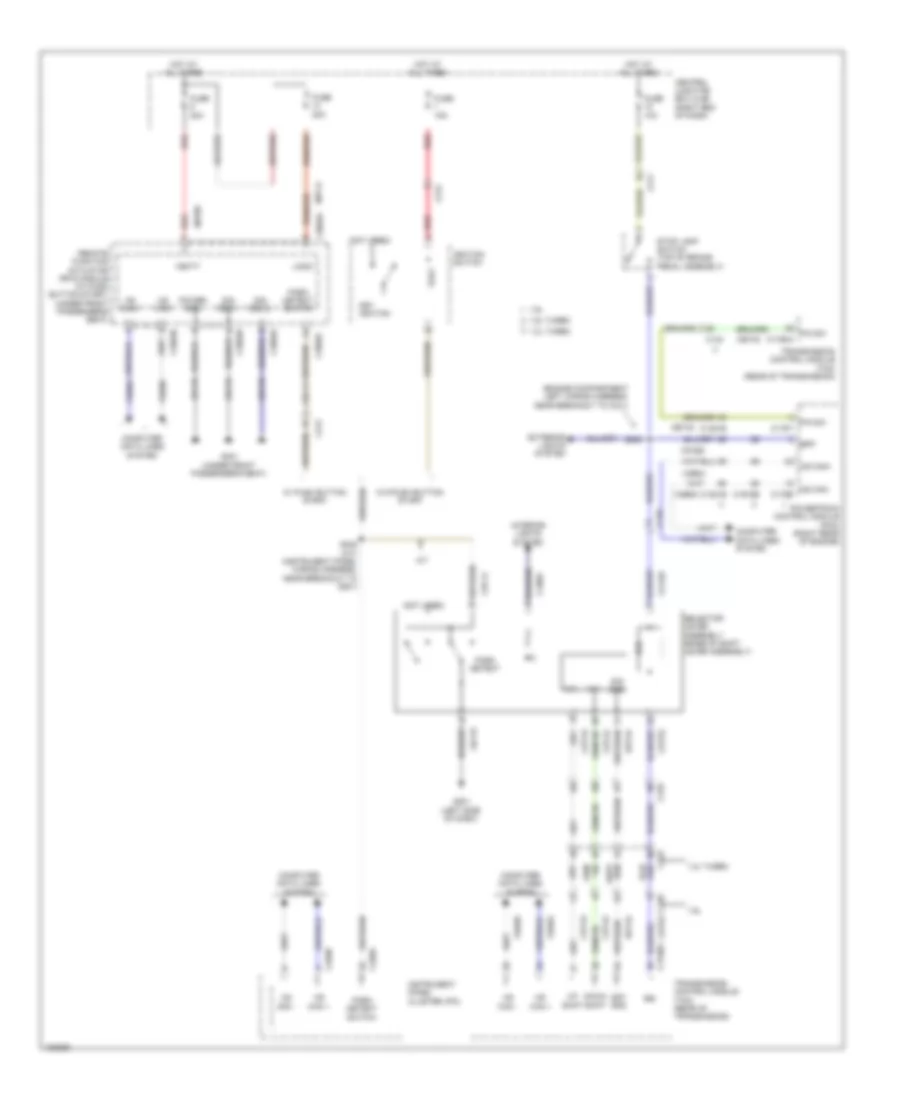
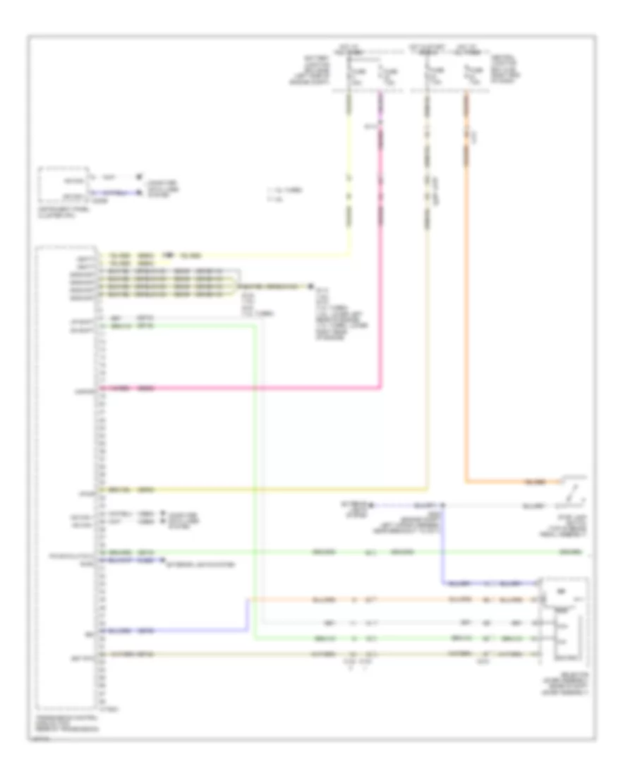
Backup Lamps Wiring Diagram for Ford Fiesta S 2014
List of elements for Backup Lamps Wiring Diagram for Ford Fiesta S 2014:
- (body main wiring harness, near breakout to c214) s263
- 1.0l turbo
- 1.6l
- 1.6l turbo
- A/t
- Auto dimming interior mirror unit
- Battery junction box (bjb) (left side of engine compt)
- Body control module (bcm) (lower right side of dash)
- C133
- C140
- C1750a
- C211
- C214
- C2280d
- Central junction box (cjb) (right end of dash)
- Cet47
- Cls28
- Computer data lines system
- Fuse 6 10a
- G301 (under front passenger's seat)
- G302 (under driver's seat)
- Global positioning system module (w/ sync) (in overhead console)
- Hot in start or run
- Hs can+
- Hs can-
- Left rear lamp assembly (5 door)
- Left reversing lamp assembly (4 door)
- M/t
- Reverse
- Reversing lamp relay
- Reversing lamp switch (top of transmission assembly)
- Right rear lamp assembly (5 door)
- Right reversing lamp assembly (4 door)
- Rlrc
- S121 (engine compt left wiring harness, near breakout to battery junction box)
- S403
- Transmission control module (tcm) (rear of transmission)
- Vdb04
- Vdb05
- W/ rain sensor
- W/o rain sensor
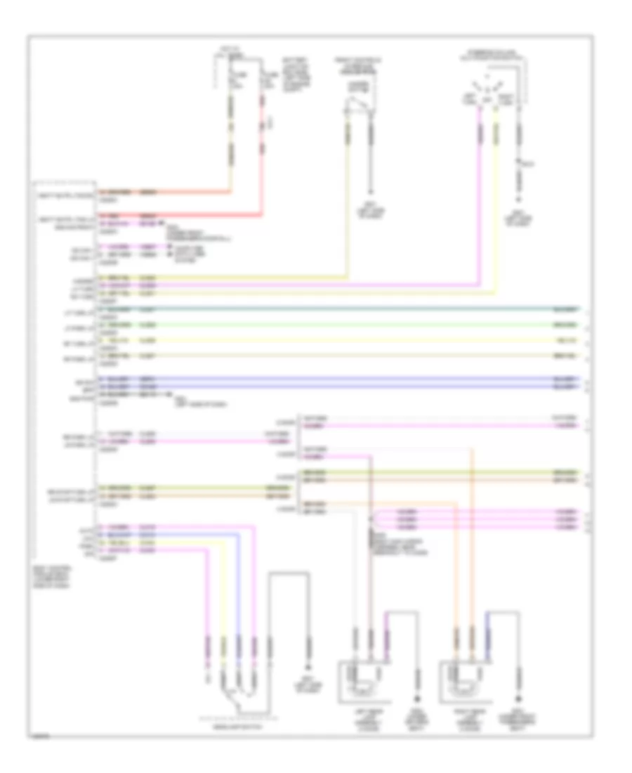
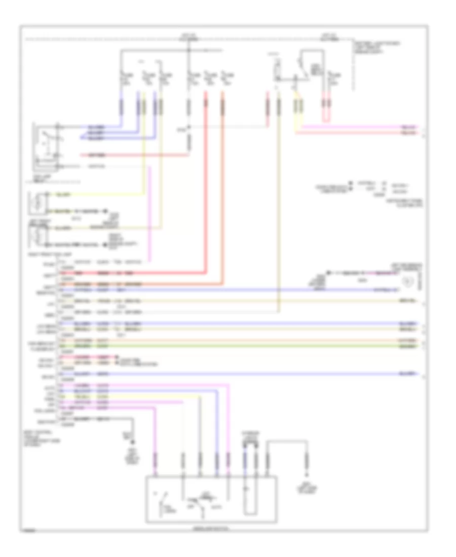
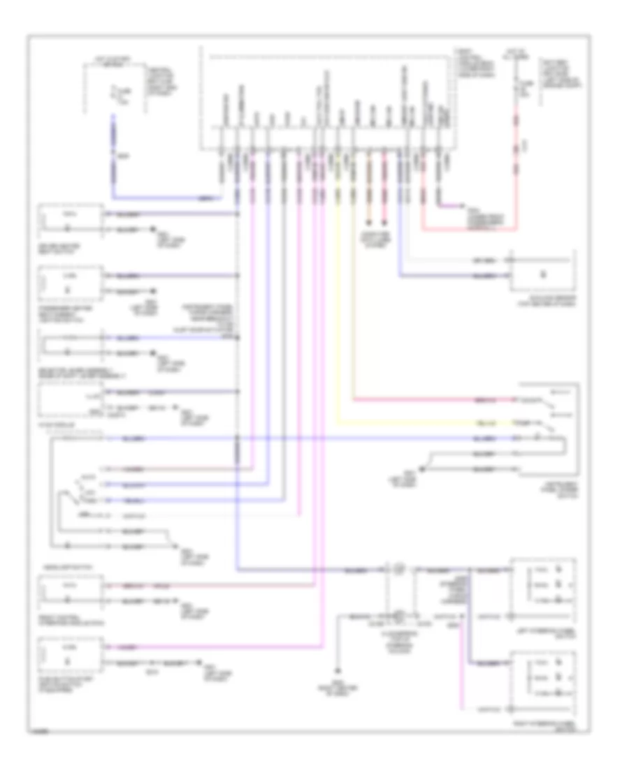
Exterior Lamps Wiring Diagram (1 of 3) for Ford Fiesta S 2014
List of elements for Exterior Lamps Wiring Diagram (1 of 3) for Ford Fiesta S 2014:
- 4 door
- 5 door
- Auto
- Battery junction box (bjb) (left side of engine compt)
- Body control module (bcm) (lower right side of dash)
- Bpp
- C211
- C2280a
- C2280b
- C2280c
- C2280d
- C2280e
- C2280f
- C2280g
- Cbp21
- Cca26
- Clf18
- Clf19
- Clf23
- Clf24
- Cls06
- Cls07
- Cls08
- Cls09
- Cls21
- Cls23
- Cls25
- Cls27
- Cls32
- Cls39
- Cls41
- Computer data lines system
- Front controls interface module (fcim)
- Fuse 20a
- Fuse 30a
- G201 (left side of dash)
- G301 (under front passenger's seat)
- G302 (under driver's seat)
- G304 (under front passenger's door sill)
- Gd115
- Gd156
- Gnd pwr
- Gnd sig front
- Hazard
- Hazard switch
- Headlamp switch
- Hot at all times
- Ign sw
- Left rear lamp assembly (4 door)
- Left turn
- Lf park lp
- Lf turn lp
- Lh turn
- Low
- Lr park lp
- Lr stop/turn lp
- Ms can +
- Ms can -
- Off
- Park
- Red
- Rf park lp
- Rf turn lp
- Rh turn
- Right rear lamp assembly (4 door)
- Right turn
- Rr park lp
- Rr stop/turn lp
- S218
- S405 (body main wiring harness, near breakout to c3209)
- Sbb06
- Sbb25
- Steering column multifunction switch
- Turn stop/
- Vbatt extr ltng lh
- Vbatt extr ltng rh
- Vdb06
- Vdb07
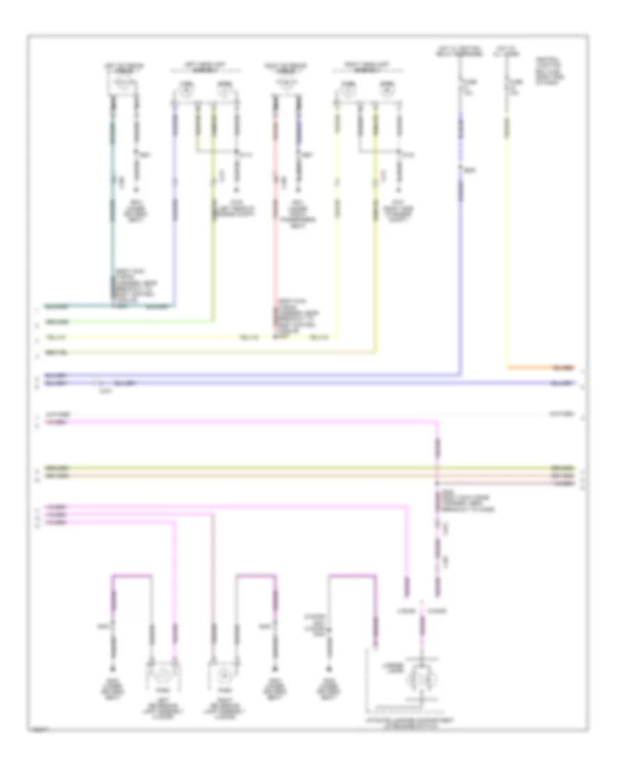
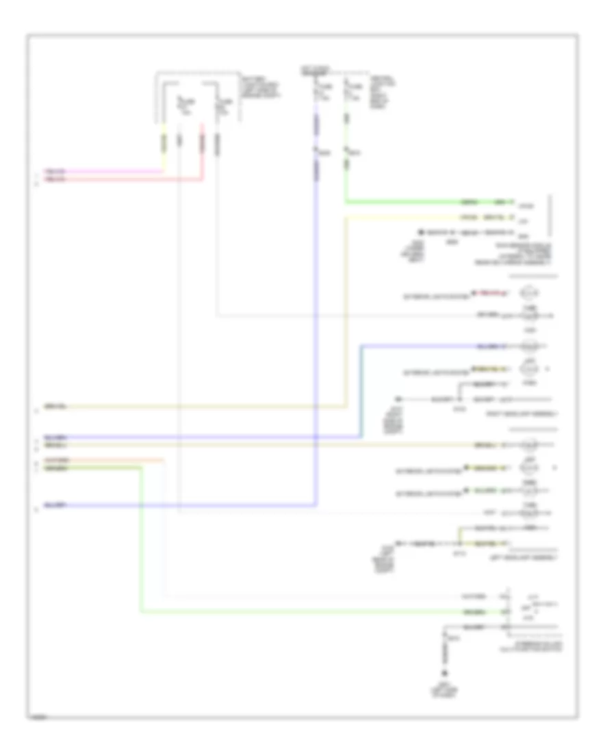
Exterior Lamps Wiring Diagram (2 of 3) for Ford Fiesta S 2014
List of elements for Exterior Lamps Wiring Diagram (2 of 3) for Ford Fiesta S 2014:
- (5 door) s401 (4 door) s403
- 4 door
- 5 door
- C210
- C211
- C339
- C340
- C497
- C913
- Central junction box (cjb) (right end of dash)
- Fuse 10a
- G105 (left rear of engine compt)
- G107 (right side of engine compt)
- G301 (under front passenger's seat)
- G302 (under driver's seat)
- Hot at all times
- Hot w/ ignition relay energized
- Left exterior mirror
- Left headlamp assembly
- Left reversing lamp assembly (4 door)
- License lamps
- Liftgate/luggage compartment lid release switch
- Nca
- Park
- Right exterior mirror
- Right headlamp assembly
- Right reversing lamp assembly (4 door)
- S112
- S132
- S239
- S403
- S405 (body main wiring harness, near breakout to c3209)
- S501
- S601
- Turn
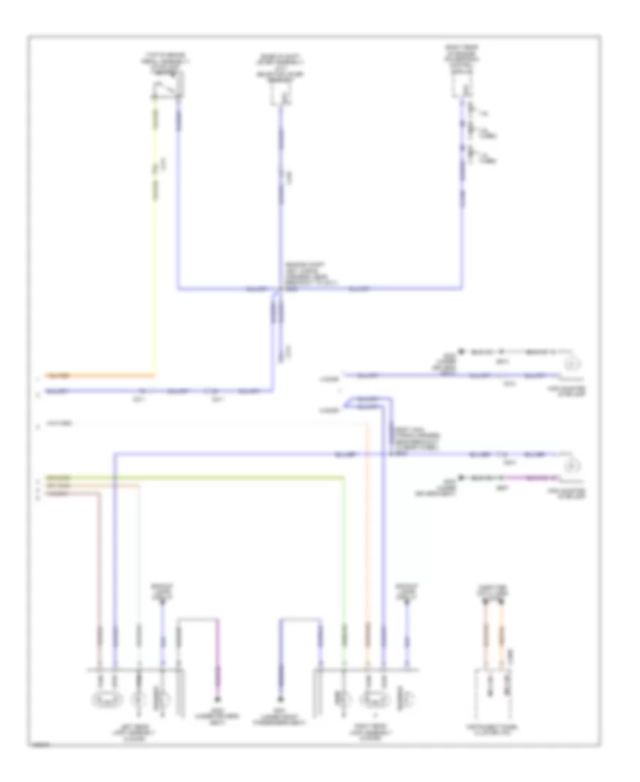
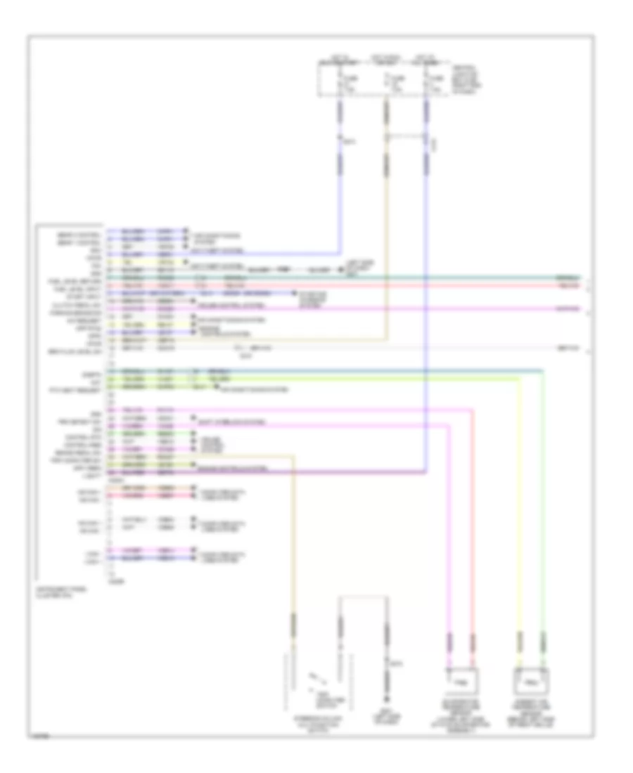
Exterior Lamps Wiring Diagram (3 of 3) for Ford Fiesta S 2014
List of elements for Exterior Lamps Wiring Diagram (3 of 3) for Ford Fiesta S 2014:
- (base of shift lever assembly) (a/t) selector lever assembly
- (body main wiring harness, near breakout to rear wheel) s302
- (engine compt left wiring harness, near breakout to c211) s202
- (right rear of engine) powertrain control module
- (top of brake pedal assembly) stoplamp switch
- 1.0l turbo
- 1.6l
- 1.6l turbo
- 4 door
- 5 door
- Backup lamps circuit
- Bpp
- C1381b
- C175b
- C1915b
- C210
- C211
- C214
- C220b
- C913
- Cca26
- Computer data lines system
- G301 (under front passenger's seat)
- G302 (under driver's seat)
- High mounted stoplamp
- Instrument panel cluster (ipc)
- Left rear lamp assembly (5 door)
- Ms can +
- Ms can -
- Park
- Reverse
- Right rear lamp assembly (5 door)
- S907
- S913
- Stop
- Turn
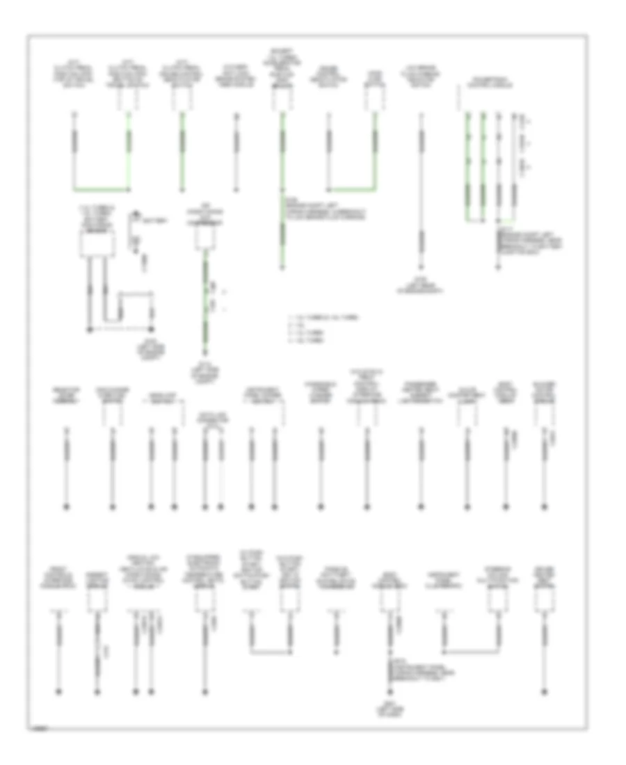
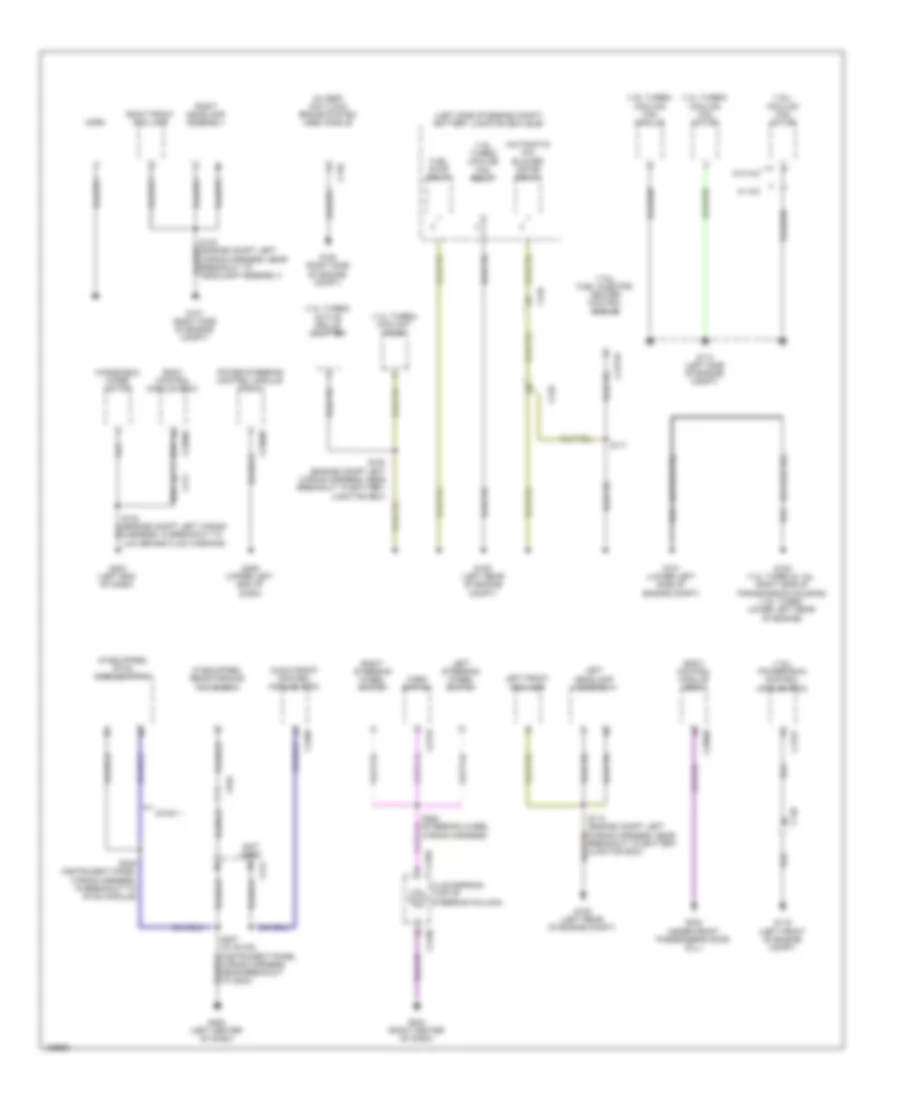
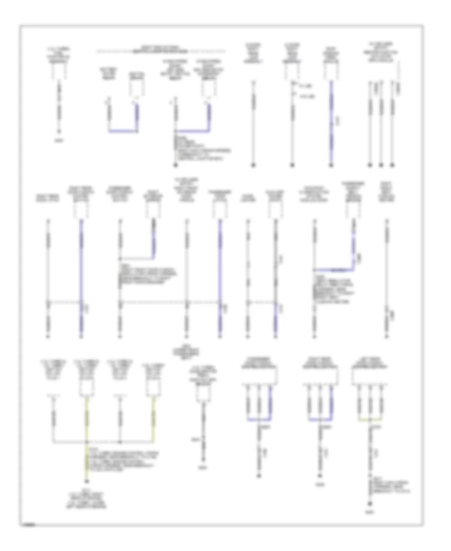
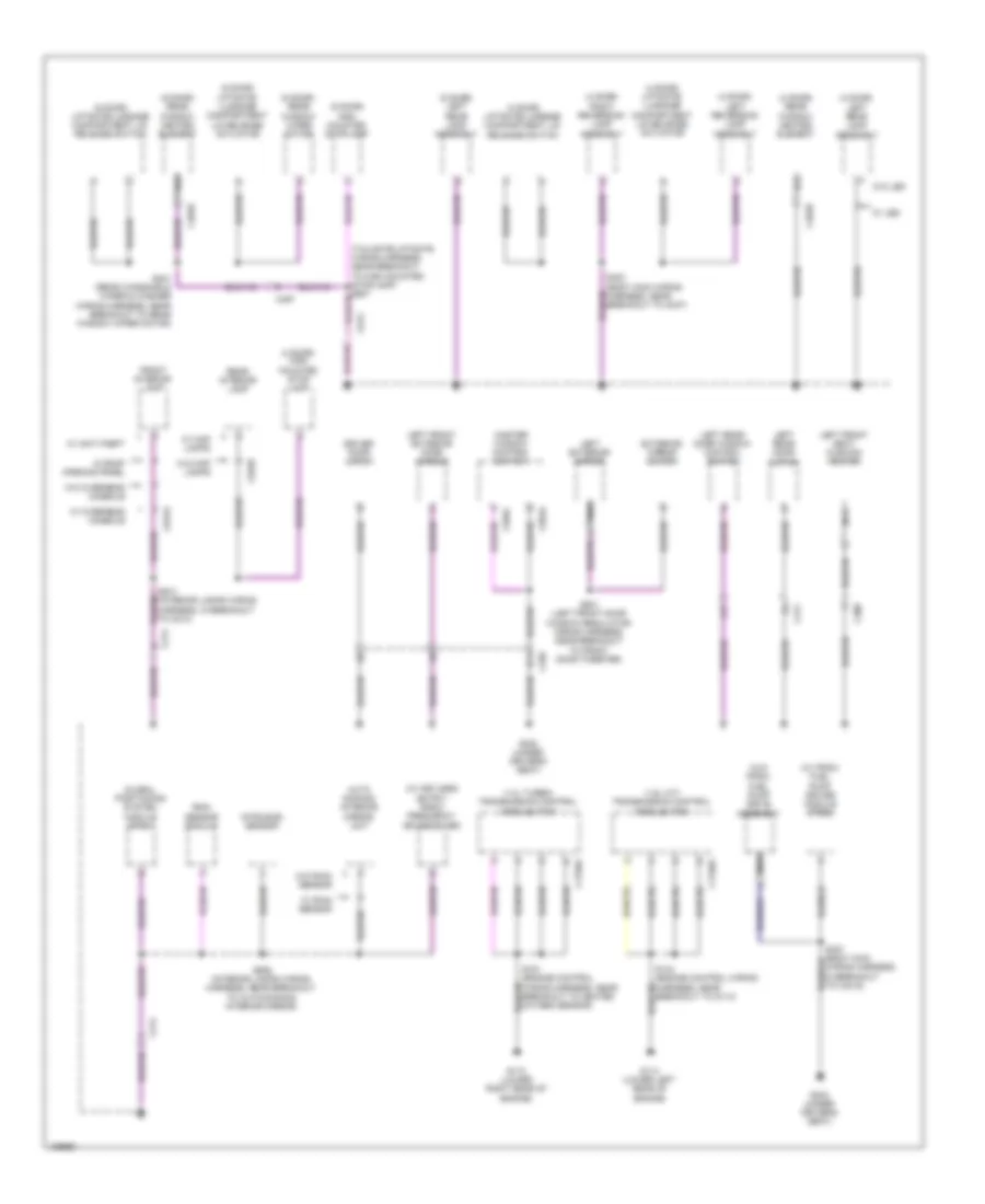
GROUND DISTRIBUTION
Ground Distribution Wiring Diagram (1 of 4) for Ford Fiesta S 2014
List of elements for Ground Distribution Wiring Diagram (1 of 4) for Ford Fiesta S 2014:
- (1.0l turbo & 1.6l turbo) battery monitoring sensor
- (except 1.0l turbo) accelerator pedal position (app) sensor
- (if equipped) electronic automatic temperature control (eatc) module
- (instrument panel wiring harness, near breakout to g201)
- (m/t) clutch pedal cruise control deactivator switch
- (m/t) clutch pedal position (cpp) (bottom of travel switch)
- (m/t) clutch pedal position (cpp) (top of travel switch)
- (manual a/c) heating, ventilation & air conditioning (hvac) control module
- (w/ push button start) ignition switch-push button start
- (w/o esp) anti-lock brake system (abs) module
- (w/o push button start) key in ignition switch
- (w/o sync 2) front control/ display interface module (fcdim)
- 1.0l turbo
- 1.0l turbo & 1.6l turbo
- 1.6l
- 1.6l turbo
- Air conditioning (a/c) compressor
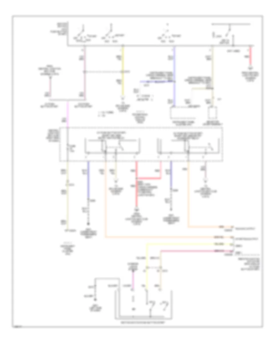
- Ambient lighting module
- Battery
- Blower motor control module
- Body control module (bcm)
- C1100b
- C133
- C1381b
- C140
- C175b
- C1915b
- C2280b
- C228a
- C2357a
- C2357b
- C297a
- C313
- Cng change over fuel switch
- Cruise control deactivator switch
- Data link connector (dlc)
- Driver heated seat switch
- Front controls interface module (fcim)
- G100 (left side of engine compt)
- G106 (left rear of engine compt)
- G112 (left side of engine compt)
- G201 (left side of dash)
- Glove compartment lamp
- Headlamp switch
- Hood ajar switch
- Instrument panel cluster (ipc)
- Instrument panel dimmer switch
- Low brake fluid warning indicator switch
- Passenger heated seat/ ambient lighting switch
- Passive anti-theft system (pats) transceiver
- Powertrain control module
- S117 (engine compt left wiring harness, near breakout to battery junction box)
- S129 (engine compt left wiring harness, in breakout to low brake fluid warning)
- Selector lever assembly
- Steering column multi-function switch
- Windshield wiper/ washer switch
Ground Distribution Wiring Diagram (2 of 4) for Ford Fiesta S 2014
List of elements for Ground Distribution Wiring Diagram (2 of 4) for Ford Fiesta S 2014:
- (1.0l turbo) active grille shutter
- (1.0l turbo) coolant pump
- (1.0l turbo) cooling fan motor
- (1.6l turbo) cooling fan module
- (1.6l turbo) cooling fan relay
- (1.6l) cooling fan motor
- (1.6l) fuel injector heater control module
- (1.6l) powertrain control module (pcm)
- (automatic a/c) blower motor relay
- (if equipped) rear parking aid camera
- (if equipped) sync module (apim)
- (left side of engine compt) battery junction box (bjb)
- (not used)
- (w/ esp) anti-lock brake system (abs) module
- Audio front control module (acm)
- Body control module (bcm)
- C1273a
- C135
- C140
- C175t
- C210
- C211
- C212
- C217b
- C218b
- C218c
- C2280a
- C2368b
- C240a
- C934
- Clockspring (top of steering column)
- Fuel pump relay
- G101 (lower left side of engine compt)
- G102 (1.0l turbo & 1.6l: right side of transmission housing) (1.6l turbo: lower left rear of engine)
- G105 (left rear of engine compt)
- G107 (right side of engine compt)
- G108 (right side of engine compt)
- G109 (left rear of engine compt)
- G113 (left side of engine compt)
- G115 (left front of engine compt)
- G202 (left center of dash)
- G203 (left end of dash)
- G204 (right center of dash)
- G205 (upper left end of dash)
- G304 (under front passenger's door sill)
- Harness, in breakout to low brake fluid warning)
- Horn
- Horn switch
- Left front fog lamp
- Left headlamp assembly
- Left steering wheel switch
- Power steering control module (pscm)
- Right front fog lamp
- Right headlamp assembly
- Right steering wheel switch
- S112 (engine compt left wiring harness, near breakout to battery junction box)
- S164 (engine compt left wiring harness, near breakout to battery junction box)
- S171
- S238 (instrument panel wiring harness, in breakout to sync module)
- S264 (steering wheel wiring harness)
- Sync 1
- W/ a/c
- W/o a/c
- Windshield wiper motor
- Wiring harness, near breakout to g204)
Ground Distribution Wiring Diagram (3 of 4) for Ford Fiesta S 2014
List of elements for Ground Distribution Wiring Diagram (3 of 4) for Ford Fiesta S 2014:
- (1.0l turbo & 1.6l turbo) ignition coil-on- plug 1
- (1.0l turbo & 1.6l turbo) ignition coil-on- plug 2
- (1.0l turbo & 1.6l turbo) ignition coil-on- plug 3
- (1.0l turbo) accelerator pedal position (app) sensor
- (1.0l turbo) fuel pump drive assembly
- (1.6l turbo) ignition coil-on- plug 4
- (4 door) right rear lamp assembly
- (5 door) right rear lamp assembly
- (if equipped) smart keyless entry accessory relay
- (if equipped) smart keyless entry ignition relay
- (right end of dash) central junction box (cjb)
- (w/ keyless entry) remote function actuator (rfa) module
- (w/ keyless entry) right front exterior door handle
- A17
- Auxiliary power point
- Battery saver relay
- C213
- C3007
- C311
- C312
- C314
- C317
- C340
- C3503a
- C3503d
- Cigar lighter
- G111 (1.0l turbo: right rear of engine) (1.6l turbo: lower left rear of engine)
- G200
- G300
- G301 (under front passenger's seat)
- G305
- G400
- Harness, near breakout to right front seat cushion heater)
- Ignition relay
- Left rear door window control switch
- Nca
- Near breakout to right front door speaker)
- Occupant classification system module (ocsm)
- Passenger door latch
- Passenger door window control switch
- Passenger safety belt tension sensor
- Right exterior mirror
- Right front seat cushion heater
- Right rear door latch
- Right rear door window control switch
- Roof opening panel module
- S143 (1.0l turbo: engine control wiring harness, near breakout to c146) (1.6l turbo: engine control wiring harness, near breakout to coil-on-plugs)
- S244
- S317 (body main wiring harness, near breakout to c314)
- W/ led
- W/o led
Ground Distribution Wiring Diagram (4 of 4) for Ford Fiesta S 2014
List of elements for Ground Distribution Wiring Diagram (4 of 4) for Ford Fiesta S 2014:
- (1.0l turbo) transmission control module (tcm)
- (1.6l a/t) transmission control module (tcm)
- (4 door) high mounted stop lamp
- (4 door) left rear lamp assembly
- (4 door) left reversing lamp assembly
- (4 door) liftgate/ luggage compartment lid release actuator
- (4 door) liftgate/luggage compartment lid release switch
- (4 door) rear window heated element
- (4 door) right reversing lamp assembly
- (5 door) high mounted stoplamp
- (5 door) left rear lamp assembly
- (5 door) liftgate/ luggage compartment lid release actuator
- (5 door) liftgate/luggage compartment lid release switch
- (5 door) rear window heated element
- (5 door) rear window wiper motor
- (w/ fpdm) fuel pump driver module (fpdm)
- (w/ keyless entry) radio frequency (rf) receiver
- (w/o fpdm) fuel pump drive assembly
- A17
- Auto dimming interior mirror unit
- B11
- C1750a
- C214
- C300
- C311
- C339
- C402b
- C497
- C504a
- C504c
- C913
- C931a
- C932b
- Driver door latch
- Exterior mirror switch
- Front interior lamp
- G110 (lower right rear of engine)
- G114 (lower left rear of engine)
- G302 (under driver's seat)
- G303 (under driver's seat)
- Global positioning system module (gpsm)
- Intrusion sensor
- Left exterior mirror
- Left front exterior door handle
- Left front seat cushion heater
- Left rear door latch
- Left rear door window control switch
- Master window control switch
- Nca
- Rain sensor module
- Rear interior lamp
- S144 (engine control wiring harness, near breakout to g114)
- S151 (engine control wiring harness, near breakout to heated oxygen sensor)
- S401 (rear windshield wiper & washer wiring harness, near breakout to rear window wiper motor)
- S403 (body main wiring harness, near breakout to c487)
- S501 (left front door window regulator wiring harness, near breakout to front door tweeter)
- S905 (interior lamps wiring harness, near breakout to auto-dimming interior mirror)
- S913 (interior lamps wiring harness, in breakout to c214)
- W/ anti-theft
- W/ led
- W/ map lamps
- W/ overhead console
- W/ rain sensor
- W/ roof opening panel
- W/o led
- W/o map lamps
- W/o overhead console
- W/o rain sensor
- Wiring harness, in breakout to c3416)
HEADLIGHTS
Headlights Wiring Diagram (1 of 2) for Ford Fiesta S 2014
List of elements for Headlights Wiring Diagram (1 of 2) for Ford Fiesta S 2014:
- (right side of engine compt) g107
- Auto
- Battery junction box (left side of engine compt)
- Body control module (lower right side of dash)
- C211
- C214
- C220b
- C2280a
- C2280b
- C2280c
- C2280d
- C2280e
- C2280f
- C2280g
- Cbp21
- Clf02
- Clf04
- Clf17
- Clf18
- Clf19
- Clf21
- Clf23
- Clf24
- Clf27
- Clfo5
- Cls12
- Cls37
- Computer data lines system
- Fflrc
- Flasher sw
- Fog lamp relay
- Fog lamps
- Fuse 10a
- Fuse 20a
- Fuse 30a
- Fuse 7.5a
- G105 (left rear of engine compt)
- G201 (left side of dash)
- G302 (under driver's seat)
- Gd115
- Gnd pwr
- Hbrc
- Headlamp switch
- High beam relay
- High beam sw
- Hot at all times
- Hs can +
- Hs can -
- Ign sw
- Instrument panel cluster (ipc)
- Interior lights system
- Left front fog lamp
- Left reversing lamp assembly
- Lin1
- Low
- Low beam
- Ms can +
- Ms can -
- Off
- Park
- Rear fog
- Red
- Right front fog lamp
- S112
- S120
- S132
- S403
- Sbb06
- Sbb25
- Vbatt
- Vdb06
- Vdb07
- Vrw26
Headlights Wiring Diagram (2 of 2) for Ford Fiesta S 2014
List of elements for Headlights Wiring Diagram (2 of 2) for Ford Fiesta S 2014:
- Battery junction box (left side of engine compt)
- Cbp02
- Central junction box (right end of dash)
- Exterior lights system
- Ftp
- Fuse 10a
- Fuse 7.5a
- G105 (left rear of engine compt)
- G107 (right side of engine compt)
- G201 (left side of dash)
- G302 (under driver's seat)
- Gd143
- Gnd
- High
- Hot in run or start
- Left headlamp assembly
- Lin1
- Low
- Off
- Park
- Rain sensor module (if equipped) (integral to inside rearview mirror assembly)
- Right headlamp assembly
- S112
- S132
- S218
- S239
- S905
- S915
- Steering column multi-function switch
- Turn
- Vpwr
- Vrw26
HORN
Horn Wiring Diagram for Ford Fiesta S 2014
List of elements for Horn Wiring Diagram for Ford Fiesta S 2014:
- Battery junction box (bjb) (left side of engine compt)
- Body control module (bcm) (lower right side of dash)
- C211
- C217a
- C217b
- C218b
- C218c
- C2280a
- C2280e
- Clockspring (top of steering column)
- Crh03
- Crh04
- Front gnd sig
- Fuse 20a
- G107 (right side of engine compt)
- G204 (right center of dash)
- G304 (under front passenger's door sill)
- Gd156
- Horn (right front of engine compt)
- Horn switch (behind horn pad)
- Hot at all times
- S264
- Sbb26
- Vbatt batt saver/ horn
- Vehicle horn output
- Vehicle horn switch
INSTRUMENT CLUSTER
Instrument Cluster Wiring Diagram (1 of 2) for Ford Fiesta S 2014
List of elements for Instrument Cluster Wiring Diagram (1 of 2) for Ford Fiesta S 2014:
- (left side of dash) g201
- (or cdc54)
- A/c request
- Aat
- Air conditioning system
- Ambient air temperature sensor (behind left side of front grille)
- Anti-theft system
- App rtn2
- App vref2
- App2
- Brake pedal sw
- Brk fluid level sw
- C210
- C212
- C220a
- C220b
- Cbp19
- Cbp21
- Cca25
- Cdc35
- Cdc41
- Ce904
- Central junction box (cjb) (right end of dash)
- Ch434
- Chp01
- Chp03
- Clutch pedal sw
- Cmc19
- Cmc25
- Computer data lines system
- Control rtn
- Control+res
- Cruise control system
- Ebhr 1 control
- Ebhr 2 control
- Engine controls system
- Evaporator temperature sensor (lower left side of hvac evaporator assembly)
- Fuel level input
- Fuel level return
- Fuse 7.5a
- G201 (left side of dash)
- Gd115
- Gnd
- Hot at all times
- Hot in run or acc
- Hot in run or start
- Hs can +
- Hs can -
- I can +
- I can -
- Instrument panel cluster (ipc)
- Le136
- Le137
- Ms can +
- Ms can -
- Parking brake sig
- Prk detect sw
- Ptc heat request
- Rdx
- Re137
- Res08
- Rh107
- Rh119
- Rmc27
- Rmc32
- S213
- S218
- Sbp03
- Shift interlock system
- Sig
- Sigrtn
- Start input
- Starting/ charging system
- Steering column multifunction switch
- Tdx
- Trip computer sw
- Trip computer switch
- V batt
- Vdb04
- Vdb05
- Vdb06
- Vdb07
- Vdb13
- Vdb14
- Ves10
- Vh406
- Vh407
- Vmc11
- Vpwr
- Vrt23
- Vrt24
Instrument Cluster Wiring Diagram (2 of 2) for Ford Fiesta S 2014
List of elements for Instrument Cluster Wiring Diagram (2 of 2) for Ford Fiesta S 2014:
- (1.6l turbo & 1.6l: lower left side of engine) (1.0l turbo: right front of engine block) engine oil pressure (eop) switch
- (on brake master cylinder reservoir) low brake fluid warning indicator switch
- (top left side fuel tank) fuel pump drive assembly
- 1.0l turbo
- 1.6l
- 1.6l turbo
- 5 door
- Body control module (bcm) (lower right side of dash)
- C1381b
- C1381e
- C175b
- C175e
- C1915b
- C1915e
- C211
- C212
- C2280e
- C2280g
- C311
- C312
- C339
- C340
- C497
- C913
- Cdc30
- Cmc24
- Computer data lines system
- Cpl26
- Cpl31
- Cpl36
- Cpl39
- Cpl44
- Driver door latch
- Ft dr ajar (drv)
- Ft dr ajar (pas)
- G106 (left rear of engine compt)
- G201 (left side of dash)
- G301 (under front passenger's seat)
- G302 (under driver's seat)
- Hs can +
- Hs can -
- Key in ignition switch (w/o push button start)
- Key in sw
- Left rear door latch
- Liftgate/luggage compartment lid release actuator (liftgate compartment lid release actuator: bottom center of liftgate) (luggage compartment lid release actuator: center rear of luggage compt)
- Ms can +
- Ms can -
- Nca
- Ops
- Parking brake warning indicator switch
- Passenger door latch
- Powertrain control module (pcm) (right rear of engine)
- Right rear door latch
- Rmc32
- Rr dr ajar (lh)
- Rr dr ajar (rh)
- S218
- S401 (5 door) s403 (4 door)
- Trunk ajar
- Vdb04
- Vdb05
- Vdb06
- Vdb07
- Vmc11
INTERIOR LIGHTS
Courtesy Lamps Wiring Diagram (1 of 2) for Ford Fiesta S 2014
List of elements for Courtesy Lamps Wiring Diagram (1 of 2) for Ford Fiesta S 2014:
- (interior lamps wiring harness, in breakout to c214) (w/ rear lamp) s906
- (w/ rear lamp) s913
- 5 door
- Battery junction box (bjb) (left side of engine compt)
- Battery saver output
- Battery saver relay
- Body control module (bcm) (lower right side of dash)
- C211
- C212
- C214
- C2280a
- C2280b
- C2280c
- C2280e
- C2280g
- C311
- C312
- C339
- C340
- C497
- C913
- C931a
- C931b
- C932a
- C932b
- Cargo lamp
- Cbp21
- Central junction box (cjb) (right end of dash)
- Cln01
- Cln02
- Cln03
- Computer data lines system
- Cpl26
- Cpl31
- Cpl36
- Cpl39
- Cpl44
- Driver door latch
- Front door ajar (drv)
- Front door ajar (pas)
- Front interior lamp
- Fuse 20a
- Fuse 30a
- Fuse 7.5a
- G201 (left of side dash)
- G201 (left side of dash)
- G301 (under front passenger's seat)
- G302 (under driver's seat)
- Gd115
- Glove compartment lamp
- Gnd power
- Hot at all times
- Hot in start or run
- Ignition sw
- Interior lamps
- Left rear door latch
- Liftgate/luggage compartment lid release actuator (bottom center of liftgate)
- Liftgate/luggage compt ajar
- Lighting ambient/moon
- Ms can+
- Ms can-
- Passenger door latch
- Rear door ajar (lh)
- Rear door ajar (rh)
- Rear interior lamp
- Red
- Right rear door latch
- S239
- S248 (body main wiring harness, near breakout to body control module)
- S401 (5 door) s403 (4 door)
- S904 (w/ rear lamp) (interior lamps wiring harness, in breakout to c214)
- Sbb06
- Sbb25
- Vbatt
- Vdb06
- Vdb07
- W/ anti-theft
- W/ map lamps
- W/ overhead console
- W/ roof opening panel
- W/o map lamps
- W/o overhead console
Courtesy Lamps Wiring Diagram (2 of 2) for Ford Fiesta S 2014
List of elements for Courtesy Lamps Wiring Diagram (2 of 2) for Ford Fiesta S 2014:
- (center console ambient lighting harness) s318
- (center console ambient lighting harness) s321
- (center console ambient lighting jumper harness)
- (instrument panel wiring harness to ambient lighting jumper harness)
- Ambient lighting module (under center console)
- C313
- C316
- C317
- G201 (left side of dash)
- Gnd
- Green
- Led rtn
- Left cupholder lamp
- Left front footwell lamp
- Left rear footwell lamp
- Passenger heated seat/ambient lighting switch
- Red
- Right cupholder lamp
- Right front footwell lamp
- Right instrument panel lamp
- Right rear footwell lamp
- S240 (instrument panel wiring harness, near breakout to passenger airbag)
- S266
- S267
- S268
- S269
- S319 (center console ambient lighting harness)
- S320 (center console ambient lighting harness)
- S322
- S323
- S324
- S325
- Sw input
- Vpwr
Instrument Illumination Wiring Diagram for Ford Fiesta S 2014
List of elements for Instrument Illumination Wiring Diagram for Ford Fiesta S 2014:
- (instrument panel wiring harness, near breakout to air inlet door actuator) s226
- Ambient light sen sig
- Auto
- Battery junction box (bjb) (left side of engine compt)
- Body control module (bcm) (lower right side of dash)
- C211
- C218b
- C218c
- C2280a
- C2280b
- C2280e
- C2280f
- C2357a
- Cbp21
- Central junction box (cjb) (right end of dash)
- Clf18
- Clf19
- Clf23
- Clf24
- Cln04
- Cln55
- Cln56
- Clockspring (top of steering column)
- Computer data lines system
- Cpl22
- Dim down
- Dim up
- Down
- Driver heated seat switch
- Front control interface module (fcim)
- Fuse 20a
- Fuse 7.5a
- G201 (left side of dash)
- G204 (right center of dash)
- G304 (under front passenger's door sill)
- Gd115
- Gd156
- Gnd
- Gnd sig front
- Headlamp switch
- Hot at all times
- Hot in start or run
- Hvac module
- Ignition sw
- Illum
- Instrument panel dimmer switch
- Ip illumination
- Keyless ign sw illu
- Left steering wheel switch
- Lock tell tail
- Low
- Ms can+
- Ms can-
- Off
- Park
- Passenger heated seat/ambient lighting switch
- Push button start ignition switch (if equipped)
- Red
- Right steering wheel switch
- Rlf14
- S218
- S239
- S264
- S265 (steering wheel wiring harness)
- Sbb25
- Selector lever assembly (base of shift lever assembly)
- Sunload sensor (top center of dash)
- Vbatt exterior lighting
- Vdb06
- Vdb07
- Vlf14
- Vln04
NAVIGATION
Navigation Wiring Diagram, with SYNC GEN 1 (1 of 2) for Ford Fiesta S 2014
List of elements for Navigation Wiring Diagram, with SYNC GEN 1 (1 of 2) for Ford Fiesta S 2014:
- Am/fm antenna
- Am/fm o/p sig
- Am/fm sig
- Antenna
- Audio front control module (acm)
- Aux in shield
- Aux1 gnd
- Aux1 l+
- Aux1 r+
- C210
- C211
- C212
- C213
- C240a
- C240b
- C311
- C312
- C339
- C340
- Cdc54
- Central junction box (right end of dash)
- Cme44
- Coax cable
- Computer data lines system
- Dme54
- Front control/display interface module (fcdim)
- Fuse 15a
- Fuse 7.5a
- G201 (left side of dash)
- G202 (left center of dash)
- Gd111
- Gd115
- Gnd
- Hot at all times
- I can+
- I can-
- Il+
- Il-
- Ir+
- Ir-
- Left front door speaker
- Left front door tweeter speaker
- Left rear door speaker
- Lf+ve
- Lf-ve
- Linbus
- Lr+ve
- Lr-ve
- Mono+
- Mono-
- Nca
- Pwr
- Pwr antenna
- Rf+ve
- Rf-ve
- Right front door speaker
- Right front door tweeter speaker
- Right rear door speaker
- Rme07
- Rme09
- Rme10
- Rme12
- Rme24
- Rme45
- Rme52
- Rme53
- Rmn14
- Rr+ve
- Rr-ve
- S201
- S225
- S227
- S262
- Sbp07
- Sbp10
- Sdars o/p sig
- Sdars sig
- Smcs
- Starting/charging system
- Swc1+
- Swc1-
- Vbatt
- Vdb13
- Vdb14
- Vmc49
- Vme07
- Vme09
- Vme10
- Vme12
- Vme14
- Vme43
- Vme45
- Vme46
- Vme52
- Vme53
- Vmn14
- W/ sdars
- W/o sdars
Navigation Wiring Diagram, with SYNC GEN 1 (2 of 2) for Ford Fiesta S 2014
List of elements for Navigation Wiring Diagram, with SYNC GEN 1 (2 of 2) for Ford Fiesta S 2014:
- (in overhead console) global positioning system module
- (instrument panel wiring harness, near breakout to g204) s236
- Audio input jack
- Audio input jack (w/o sync)
- Aux gnd
- Aux in l+
- Aux in r+
- Aux1 l+
- Aux1 r+
- C212
- C213
- C218b
- C218c
- C313
- Cet47
- Clockspring (top of steering column)
- Cls32
- Computer data lines system
- Cpl22
- Cpl75
- Dme45
- Dme52
- Dmn14
- Door lock control switch
- Door locks system
- Exterior lights system
- Front controls interface module (fcim)
- G201 (left side of dash)
- G202 (left center of dash)
- G204 (right center of dash)
- G302 (under driver's seat)
- Gd111
- Gd115
- Gd143
- Gnd
- Hazard
- Hs can+
- Hs can-
- I can+
- I can-
- Interior lights system
- Left steering wheel switch
- Lock illum
- Logic
- Mic in+
- Mic in-
- Mic sig +
- Mic sig -
- Microphone (in overhead console)
- Mono out shield
- Mono+
- Mono-
- Ms can+
- Ms can-
- Nca
- Not used
- Power distribution system
- Pwr gnd
- Redundant audio switch
- Reverse
- Rme45
- Rme52
- Rme53
- Rmm13
- Rmn14
- S233 (instrument panel wiring harness, near breakout to g204)
- S238
- S264
- S265 (steering wheel wiring harness)
- S905
- S914
- Sbp07
- Sbp10
- Seek +
- Seek -
- Shield
- Steering column multi-function switch
- Sync module (lower right center of dash)
- Usb
- Usb port
- Vbatt
- Vdb04
- Vdb05
- Vdb06
- Vdb07
- Vdb13
- Vdb14
- Vmc49
- Vme45
- Vme46
- Vme52
- Vme53
- Vmm13
- Vmn14
- Voice
- Volume +
- Volume -
- W/ overhead console
- W/o overhead console
Navigation Wiring Diagram, with SYNC GEN 2 (1 of 2) for Ford Fiesta S 2014
List of elements for Navigation Wiring Diagram, with SYNC GEN 2 (1 of 2) for Ford Fiesta S 2014:
- Am/fm antenna
- Am/fm o/p sig
- Am/fm sig
- Antenna
- Audio front control module (acm)
- Audio input jack (w/o sync)
- Aux gnd
- Aux in shield
- Aux1 gnd
- Aux1 l+
- Aux1 r+
- C210
- C211
- C212
- C213
- C240a
- C240b
- C311
- C312
- C313
- C339
- C340
- Cdc54
- Central junction box (right end of dash)
- Cls32
- Cme44
- Coax cable
- Computer data lines system
- Cpl22
- Cpl75
- Dme54
- Door lock control switch
- Door locks system
- Exterior lights system
- Front controls interface module (fcim)
- Fuse 15a
- Fuse 7.5a
- G201 (left side of dash)
- G202 (left center of dash)
- Gd111
- Gd115
- Gnd
- Hazard
- Hot at all times
- I can+
- I can-
- Il+
- Il-
- Ir+
- Ir-
- Left front door speaker
- Left front door tweeter speaker
- Left rear door speaker
- Lf +ve
- Lf -ve
- Lock illum
- Logic
- Lr +ve
- Lr -ve
- Mono+
- Mono-
- Nca
- Power distribution system
- Pwr
- Pwr antenna
- Rf +ve
- Rf -ve
- Right front door speaker
- Right front door tweeter speaker
- Right rear door speaker
- Rme07
- Rme09
- Rme10
- Rme12
- Rme45
- Rme52
- Rme53
- Rmn14
- Rr +ve
- Rr -ve
- S201
- S225
- S227
- Sbp07
- Sbp10
- Sdars o/p sig
- Sdars sig
- Sdl+
- Sdl-
- Smcs
- Starting/charging system
- Vbatt
- Vdb13
- Vdb14
- Vme07
- Vme09
- Vme10
- Vme12
- Vme43
- Vme45
- Vme46
- Vme52
- Vme53
- Vme90
- Vme91
- Vmn14
- W/ sdars
- W/o sdars
Navigation Wiring Diagram, with SYNC GEN 2 (2 of 2) for Ford Fiesta S 2014
List of elements for Navigation Wiring Diagram, with SYNC GEN 2 (2 of 2) for Ford Fiesta S 2014:
- (in overhead console) global positioning system module
- (instrument panel wiring harness, near breakout to g204) s233
- (left center of dash) g202
- Aux l+
- Aux l-
- Aux r+
- Aux r-
- C212
- C213
- C218b
- C218c
- C315
- Cet47
- Clockspring (top of steering column)
- Computer data lines system
- Dme45
- Dme52
- Dmn14
- Exterior lights system
- G204 (right center of dash)
- G302 (under driver's seat)
- Gd111
- Gd143
- Gnd
- Hs can+
- Hs can-
- I can+
- I can-
- Interior lights system
- Left steering wheel switch
- Lme89
- Media gnd
- Media hub
- Mic in+
- Mic in-
- Mic sig +
- Mic sig -
- Microphone (in overhead console)
- Mono+
- Mono-
- Ms can+
- Ms can-
- Navigation system
- Nca
- Not used
- Power distribution system
- Pwr gnd
- Redundant audio switch
- Reverse
- Rme24
- Rme45
- Rme46
- Rme52
- Rme53
- Rme89
- Rmm13
- Rmn14
- Rmp19
- Rvc video+
- Rvc video-
- S236 (instrument panel wiring harness, near breakout to g204)
- S238
- S264
- S265 (steering wheel wiring harness)
- S905
- S914
- Sbp07
- Sbp10
- Sdl+
- Sdl-
- Seek +
- Seek -
- Shield
- Steering column multi-function switch
- Swc1+
- Swc1-
- Sync b+
- Sync module (lower right center of dash)
- Usb
- Vbatt
- Vdb04
- Vdb05
- Vdb06
- Vdb07
- Vdb13
- Vdb14
- Vme14
- Vme45
- Vme46
- Vme52
- Vme53
- Vme90
- Vme91
- Vmm13
- Vmn14
- Vmp19
- Voice
- Volume +
- Volume -
- W/ overhead console
- W/o overhead console
Parking Assistant Wiring Diagram for Ford Fiesta S 2014
List of elements for Parking Assistant Wiring Diagram for Ford Fiesta S 2014:
- (rear parking aid wiring harness, near breakout to c411) s408
- Body control module (bcm) (lower right side of dash)
- C2280b
- C2280e
- C2280g
- C411
- Cbp21
- Central junction box (right end of dash)
- Computer data lines system
- Fuse 7.5a
- G201 (left side of dash)
- Gd115
- Hot in run or start
- Left rear inner parking aid sensor (behind left side of rear bumper)
- Left rear outer parking aid sensor (behind left end of rear bumper)
- Lmp07
- Micro
- Ms can +
- Ms can -
- Pwr gnd
- Rear inner lt snsr
- Rear inner rt snsr
- Rear outer lt snsr
- Rear outer rt snsr
- Rear sensor gnd
- Rear sensor pwr
- Right rear inner parking aid sensor (behind right side of rear bumper)
- Right rear outer parking aid sensor (behind right end of rear bumper)
- Rmp07
- S239
- S409 (rear parking aid wiring harness, near breakout to c411)
- Vdb06
- Vdb07
- Vmp14
- Vmp16
- Vmp17
- Vpm15
- Vpwr
Rear Camera Wiring Diagram for Ford Fiesta S 2014
List of elements for Rear Camera Wiring Diagram for Ford Fiesta S 2014:
- Body control module (lower right side of dash)
- C212
- C934
- Central junction box (right end of dash)
- Choke
- Computer data lines system
- Electronics
- Fuse 10a
- Fuse 15a
- G202 (left center of dash)
- Gd111
- Hot at all times
- Hot w/ ignition relay energized
- Hs can+
- Hs can-
- Lin
- Nca
- Pwr gnd
- Rear camera video+
- Rear camera video-
- Rear parking aid camera (top center of liftgate)
- Rmp19
- S201 (w/ sync)
- S227
- S2280g
- S238
- S249
- S280 (body main wiring harness, near breakout to body control module)
- Sbp10
- Sync module (apim) (lower right center of dash)
- Un comm
- Vbatt
- Vdb04
- Vdb05
- Vmp19
- Vrt26
POWER DISTRIBUTION
Power Distribution Wiring Diagram (1 of 6) for Ford Fiesta S 2014
List of elements for Power Distribution Wiring Diagram (1 of 6) for Ford Fiesta S 2014:
- (1.0l turbo)
- (1.6l)
- (1.6l: engine control wiring harness, near breakout to g114) (1.0l turbo: engine control wiring harness, near breakout to heated oxygen sensor) s100
- (engine compartment left wiring harness, near breakout to battery junction box) s114
- 1.0l turbo
- 1.6l & 1.6l turbo
- A/c clutch relay
- Anti-lock brake system (abs) module
- Auxiliary relay box (w/ electric booster heater) (left front of engine compt)
- Battery
- Battery junction box (bjb) (left side of engine compt)
- Battery monitoring sensor (1.0l turbo & 1.6l turbo)
- Blower motor relay
- Body control module (bcm)
- C1100a
- C133
- C140
- C1617a
- C1617b
- C1617c
- C1617d
- C1617e
- C1750a
- C175b
- C210
- C211
- C2280a
- C2280c
- C2368c
- Cooling fan relay
- Electric booster heater relay 1
- Electric booster heater relay 2
- Evaporative emission canister vent valve
- Fuse 10a
- Fuse 15a
- Fuse 20a
- Fuse 30a
- Fuse 3a
- Fuse 40a
- Fuse 60a
- Fuse 7.5a
- Generator
- High current battery junction box (bjb) (at battery)
- High fan control (hfc) relay
- In-line fuse 1 (on battery positive (+) post)
- Low fan control (lfc) relay
- Mega fuse 1 450a
- Mega fuse 2 60a
- Mega fuse 3 200a
- Mega fuse 4 70a
- Mega fuse 5 50a
- Power steering control module (pscm)
- Powertrain control module (pcm) (1.6l)
- Red
- S156 (1.0l turbo) red (engine control wiring harness, near breakout to heated oxygen sensor)
- Starter inhibit relay
- Starter motor
- To battery junction box (bjb) (diagram 2 of 6)
- To fuse 17 (diagram 6 of 6)
- To fuse 5 (diagram 2 of 6)
- Transmission control module (tcm) (a/t)
Power Distribution Wiring Diagram (2 of 6) for Ford Fiesta S 2014
List of elements for Power Distribution Wiring Diagram (2 of 6) for Ford Fiesta S 2014:
- (1.0l turbo: engine control wiring harness, near breakout to generator) (1.6l: engine control wiring harness, near breakout to g114) (1.6l turbo: engine control wiring harness, near breakout to turbocharger bypass valve) s103
- (1.6l turbo: engine control wiring harness, near breakout to c110) (1.0l turbo: engine control wiring harness, near breakout to intake camshaft position sensor) s108
- (engine compt left wiring harness, near breakout to battery junction box) s165
- (engine compt left wiring harness, near breakout to g109) s122
- (instrument panel wiring harness, near breakout to g201) s213
- 1.0l turbo
- 1.0l turbo & 1.6l turbo
- 1.6l
- 1.6l turbo
- Accelerator pedal position (app) sensor
- Active grille shutter
- Air conditioning a/c compressor control solenoid
- Anti-lock brake system (abs) module
- Battery junction box (bjb) (left side of engine compt)
- Blower motor relay
- Body control module (bcm)
- C1273a
- C133
- C1381b
- C140
- C1750a
- C175b
- C1915b
- C210
- C211
- C212
- C220a
- C2280b
- C2357a
- C2368a
- C310a
- C3503b
- Catalyst monitor sensor
- Central junction box (cjb) (right end of dash)
- Coolant pump
- From a fuse 10 (diagram 1 of 6)
- From battery junction box (bjb) (diagram 1 of 6)
- From central junction box (cjb) (diagram 4 of 6)
- From ignition switch (diagram 4 of 6)
- From splice s114 (diagram 1 of 6)
- Fuel injector heater control module
- Fuse 10a
- Fuse 15a
- Fuse 20a
- Fuse 60a
- Fuse 7.5a
- G301 (under front passenger's seat)
- Heated oxygen sensor (ho2s)
- Hvac control module
- Ignition coil
- Ignition coil-on plug 1
- Ignition coil-on plug 2
- Ignition coil-on plug 3
- Ignition coil-on plug 4 (1.6l turbo)
- Ignition relay
- Instrument panel cluster (ipc)
- Passive anti-theft transceiver (w/o keyless entry)
- Pcm power relay
- Power steering control module (pscm)
- Powertrain control module (pcm)
- Remote function actuator (rfa) module (w/ keyless entry)
- Restraints control module (rcm)
- S228
- S239 (instrument panel wiring harness, near breakout to passenger airbag)
- S256 (w/ rear power point)
- S259 (body main wiring harness, in breakout to central junction box)
- To central junction box (cjb) (diagram 5 of 6)
- To fuse 24 (diagram 6 of 6)
- To splice s252 (diagram 3 of 6)
- Transmission control module (tcm)
- W/ push button start
- W/o push button start
Power Distribution Wiring Diagram (3 of 6) for Ford Fiesta S 2014
List of elements for Power Distribution Wiring Diagram (3 of 6) for Ford Fiesta S 2014:
- (body main wiring harness, near breakout to body control module) s252
- (instrument panel wiring harness, in breakout to c212) (w/ sync) s201
- (instrument panel wiring harness, near breakout to passenger air bag) s225
- (interior lamps wiring harness, near breakout to auto-dimming interior mirror) s914
- (left front door window regulator wiring harness, in breakout to c339) (w/ power windows) s504
- Audio front control module (acm)
- Automatic a/c
- Auxiliary power point
- Battery saver relay
- Body control module (bcm)
- Breakout to central junction box)
- C211
- C212
- C213
- C220a
- C2280c
- C228a
- C2357a
- C240a
- C314
- C317
- C339 a8
- C3503a
- C504a
- Central junction box (cjb) (right end of dash)
- Cigar lighter
- Data link connector (dlc)
- Electronic automatic temperature control (eatc) module
- Exterior rear view mirror switch
- From battery junction box (bjb) f (diagram 2 of 6)
- Front control/ display interface module (fcdim)
- Front controls interface module (fcim)
- Fuse 10a
- Fuse 15a
- Fuse 20a
- Fuse 5a
- Fuse 7.5a
- G301 (under front passenger's seat)
- Global positioning system module
- Heating ventilation & air conditioning (hvac) control module
- Instrument panel cluster (ipc)
- Interior lights system
- Intrusion sensor
- Manual a/c
- Master window control switch (w/ power window)
- Radio frequency (rf) receiver
- Red
- Remote function actuator (rfa) module (w/ keyless entry)
- Roof opening panel module
- S248 (body main wiring harness, near breakout to body control module)
- S256
- Stop lamp switch
- Sync module (apim) (w/ sync)
- To central jinction box (cjb) (diagram 6 of 6)
- To ignition switch (diagram 4 of 6)
- To splice s253 (diagram 4 of 6)
- W/ keyless entry
- W/ push button start
- W/o push button start
Power Distribution Wiring Diagram (4 of 6) for Ford Fiesta S 2014
List of elements for Power Distribution Wiring Diagram (4 of 6) for Ford Fiesta S 2014:
- (instrument panel wiring harness, near breakout to g201) (a/t) s245
- (instrument panel wiring harness, near breakout to g201) s230
- (not used)
- (w/ push button start) smart keyless entry accessory relay
- (w/ push button start) smart keyless entry ignition relay
- 1.0l turbo
- 1.6l
- A/t
- Acc
- C1381b
- C175b
- C210
- C212
- C220a
- C3503b
- C3503c
- Central junction box (cjb) (right end of dash)
- From central junction box (cjb) (diagram 3 of 6)
- From central junction box (cjb) (diagram 4 of 6)
- From central junction box (diagram 3 of 6)
- Fuse 7.5a
- G201 (left side of dash)
- G301 (under front passenger's seat)
- Ignition switch (w/o push button start)
- Ignition switch-push button start
- Instrument panel cluster (ipc)
- Interior lights system
- Key in ignition
- Lock
- Off
- Powertrain control module (pcm)
- Red
- Remote function actuator (rfa) module (w/ push button start)
- Run
- Run/acc output
- S218
- S253 (body main red wiring harness, in breakout to central junction box)
- S256
- Selector lever assembly
- Ssb 1
- Ssb 2
- Start
- Start/run output
- Sw 1
- Sw 2
- To central junction box (cjb) (diagram 4 of 6)
- To splice s259 (diagram 2 of 6)
- W/ push button start
- W/o push button start
Power Distribution Wiring Diagram (5 of 6) for Ford Fiesta S 2014
List of elements for Power Distribution Wiring Diagram (5 of 6) for Ford Fiesta S 2014:
- (body main wiring harness, in breakout to central junction box) s254
- (body main wiring harness, near breakout to c214) s261
- (body main wiring harness, near breakout to c340) s310
- (engine compt left wiring harness, near breakout to battery junction box) s121
- (interior lamps wiring harness, in breakout to c214) (w/ rain sensor) s915
- 1.0l turbo
- 1.6l
- 1.6l turbo
- A/t
- Auto dimming interior mirror unit
- Auxiliary relay box (left front of engine compt)
- Battery junction box (bjb) (left side of engine compt)
- Body control module (bcm)
- C133
- C140
- C211
- C212
- C213
- C214
- C2280b
- C3007
- C934
- Central junction box (cjb) (right end of dash)
- Driver heated seat relay
- Electric booster heater relay 1
- Electric booster heater relay 2
- From central junction box (cjb) (diagram 2 of 6)
- From fuse 6 l (diagram 5 of 6)
- Fuse 10a
- Fuse 15a
- Fuse 20a
- Fuse 7.5a
- M/t
- Occupant classification system module (ocsm)
- Passenger air bag deactivation (pad) indicator
- Passenger heated seat relay
- Rain sensor module (if equipped)
- Rear parking aid camera (w/ rearview camera)
- Reversing lamp switch
- Reversing lamps relay
- Roof opening panel module
- S166 (engine compt left wiring harness, near breakout to g107)
- To fuse 2 (diagram 5 of 6)
- Windshield wiper/ washer switch
Power Distribution Wiring Diagram (6 of 6) for Ford Fiesta S 2014
List of elements for Power Distribution Wiring Diagram (6 of 6) for Ford Fiesta S 2014:
- (1.0l turbo: engine control wiring harness, near breakout to c146) (1.6l: engine control wiring harness, near breakout to fuel injector 2) (1.6l turbo: engine control wiring harness, near breakout to turbocharger bypass valve) s109
- (body main wiring harness, in breakout to central junction box) s282
- (not used)
- 1.0l turbo & 1.6l turbo
- 1.6l
- A/c clutch relay
- A15 c339
- Accessory relay
- Air conditioning (a/c) clutch relay
- B14
- Battery junction box (bjb) (left side of engine compt)
- Body control module (bcm)
- C133
- C140
- C211
- C212
- C2280a
- C2280c
- C2280d
- C340 a15
- C504a
- C504c
- Central junction box (bjb) (right end of dash)
- Central junction box (cjb) (right end of dash)
- Cooling fan relay (1.6l & 1.6l turbo)
- Degas valve (1.6l turbo)
- Electronic compressor bypass valve (1.0l turbo)
- Evaporative emission canister purge valve
- Exhaust gas reorculation (egr) cooler bypass valve (1.6l turbo)
- Exhaust variable camshaft timing (vct) oil control solenoid
- Fog lamp relay
- From fuse 18 m (diagram 2 of 6)
- From n fuse 6 (diagram 1 of 6)
- From o splice s262 (diagram 3 of 6)
- Fuel pump relay
- Fuse 10a
- Fuse 15a
- Fuse 20a
- Fuse 30a
- Fuse 60a
- Fuse 7.5a
- High beam relay
- High fan control (hfc) relay
- Intake variable camshaft timing (vct) oil control solenoid
- Low fan control (lfc) relay
- Master window control switch
- Oil pressure control solenoid (1.0l turbo)
- Passenger door window control switch
- Red
- S120 (engine compt left wiring harness, near breakout to battery junction box)
- S163 (engine compt left wiring harness, near breakout to battery junction box)
- S311 (body main wiring harness, near breakout to c340)
- Turbocharger bypass valve (1.6l turbo)
- Turbocharger wastegate regulating valve solenoid (tcwrvs) (1.0l turbo)
- Variable camshaft timing 11 (vct11) solenoid (1.0l turbo)
- Variable camshaft timing 12 (vct12) solenoid (1.0l turbo)
- Wastage control solenoid
POWER DOOR LOCKS
Power Door Locks Wiring Diagram, with Keyless Entry (1 of 4) for Ford Fiesta S 2014
List of elements for Power Door Locks Wiring Diagram, with Keyless Entry (1 of 4) for Ford Fiesta S 2014:
- (body main wiring harness, in breakout to central junction box) s260
- (body main wiring harness, near breakout to c339)
- A1 c340
- A10
- A12
- A13
- Alarm horn
- Anti-theft horn (right side of luggage compt)
- B5 c339
- Battery junction box (left side of engine compt)
- Body control module (lower right side of dash)
- C211
- C220b
- C2280b
- C2280c
- C2280d
- C2280e
- C2280f
- C2280g
- Clf18
- Computer data lines system
- Cpl11
- Cpl13
- Cpl22
- Cpl25
- Cpl26
- Cpl28
- Cpl29
- Cpl30
- Cpl31
- Cpl36
- Cpl39
- Cpl51
- Cpl75
- Crt02
- Door lock control switch
- Driver door latch
- Drv front dr ajar
- Front controls interface module (fcim)
- Fuse 30a
- G106 (left rear of engine compt)
- G201 (left side of dash)
- G301 (under front passenger's seat)
- G302 (under driver's seat)
- Gd115
- Gnd pwr
- Headlights system
- Hood ajar
- Hood ajar switch (center front of engine compt)
- Hot at all times
- Instrument panel cluster (ipc)
- Ip center lk button
- Lock illumination
- Lock mtr
- Lock telltale
- Low
- Lt rear dr ajar
- Ms can +
- Ms can -
- Pas front door ajar
- Passenger door latch
- Reset
- Reset sw (drv)
- Rt rear dr ajar
- S129
- S314
- Sbb06
- Set
- Set sw (drv)
- Unlock
- Unlock drv dr mtr
- Unlock mtr
- Unlock sw
- Vbatt
- Vdb06
- Vdb07
Power Door Locks Wiring Diagram, with Keyless Entry (2 of 4) for Ford Fiesta S 2014
List of elements for Power Door Locks Wiring Diagram, with Keyless Entry (2 of 4) for Ford Fiesta S 2014:
- (body main wiring harness, near breakout to c339)
- (left side of dash) g201
- A12
- A13
- A4 c311
- A4 c312
- C212
- G301 (under front passenger's seat)
- G302 (under driver's seat)
- Gnd
- Left rear door latch
- Passive anti-theft system front antenna (under right front of center console)
- Passive anti-theft system transceiver (steering column)
- Pwr
- Right rear door latch
- S218
- S315
- Unlock
Power Door Locks Wiring Diagram, with Keyless Entry (3 of 4) for Ford Fiesta S 2014
List of elements for Power Door Locks Wiring Diagram, with Keyless Entry (3 of 4) for Ford Fiesta S 2014:
- Ant +
- Ant -
- C212
- C3503a
- C3503d
- C3503e
- C495
- Cbp13
- Center +
- Center -
- Central junction box (right end of dash)
- Front +
- Front -
- Fuse 20a
- Fuse 7.5a
- G301 (under front passenger's seat)
- Gd145
- Hot at all times
- Keyless entry rear antenna (behind center of rear bumper)
- Left +
- Left -
- Logic
- Passive anti-theft system center antenna (under center center console)
- Passive anti-theft system rear antenna (under left rear seat)
- Pats pwr
- Pats rx
- Pats tx
- Pwr gnd
- Rear +
- Rear -
- Red
- Remote function actuator module (under front passenger's seat)
- Right +
- Right -
- Rpk01
- Rpk02
- Rpk05
- Rpk06
- Rpk07
- Rpk08
- S262
- Sbp09
- Sbp14
- Sig gnd 1
- Sig gnd 2
- Vbatt
- Vpk01
- Vpk02
- Vpk05
- Vpk06
- Vpk07
- Vpk08
- Vrt23
- Vrt24
Power Door Locks Wiring Diagram, with Keyless Entry (4 of 4) for Ford Fiesta S 2014
List of elements for Power Door Locks Wiring Diagram, with Keyless Entry (4 of 4) for Ford Fiesta S 2014:
- A10
- Anti-theft system
- Brake pedal sw
- C213
- C339
- C340
- C3503b
- C3503c
- C3503d
- Cca25
- Cdc32
- Cdc35
- Cdc41
- Ce903
- Clutch 2
- Computer data lines system
- Cpk34
- Cpk35
- Cpl10
- Cpl27
- Cpl32
- Cruise control system
- G301 (under front passenger's seat)
- G302 (under driver's seat)
- Gnd
- Hs can +
- Hs can -
- Ign monitor
- K-line
- K-line irx
- Left front exterior door handle
- Ms can +
- Ms can -
- Park detect sw
- Power distribution system
- Radio frequency receiver (in overhead console)
- Release sw
- Remote function actuator module (under front passenger's seat)
- Right front exterior door handle
- Run/acc output
- S905
- S914
- Shift interlock system
- Smcs
- Ssb 1
- Ssb 2
- Start/run out
- Starting/charging system
- Sw left
- Sw right
- Trunk, tailgate, fuel doors system
- Vbatt
- Vdb04
- Vdb05
- Vdb06
- Vdb07
- Vdb10
- Za101
- Za102
Power Door Locks Wiring Diagram, without Keyless Entry (1 of 2) for Ford Fiesta S 2014
List of elements for Power Door Locks Wiring Diagram, without Keyless Entry (1 of 2) for Ford Fiesta S 2014:
- (body main wiring harness, near breakout to central junction box) s260
- A10
- A12
- A13
- Alarm horn
- Battery junction box (left side of engine compt)
- Body control module (lower right side of dash)
- C211
- C2280b
- C2280c
- C2280d
- C2280e
- C2280f
- C2280g
- C339 b5
- C340 b5
- Clf18
- Computer data lines system
- Cpl11
- Cpl13
- Cpl22
- Cpl25
- Cpl26
- Cpl28
- Cpl29
- Cpl30
- Cpl31
- Cpl36
- Cpl39
- Cpl51
- Cpl75
- Crt02
- Driver door latch
- Drv front dr ajar
- Fuse 30a
- G201 (left side of dash)
- G301 (under front passenger's seat)
- G302 (under driver's seat)
- Gd115
- Gnd pwr
- Headlights system
- Hood ajar
- Hot at all times
- Ip center lk button
- Lock mtr
- Lock telltale
- Low
- Lt rear dr ajar
- Ms can +
- Ms can -
- Pas front door ajar
- Passenger door latch
- Reset
- Reset sw (drv)
- Rt rear fr ajar
- S314 (body main wiring harness, near breakout to c339)
- Sbb06
- Set
- Set sw (drv)
- Unlock
- Unlock drv dr mtr
- Unlock mtr
- Unlock sw
- Vbatt
- Vdb06
- Vdb07
Power Door Locks Wiring Diagram, without Keyless Entry (2 of 2) for Ford Fiesta S 2014
List of elements for Power Door Locks Wiring Diagram, without Keyless Entry (2 of 2) for Ford Fiesta S 2014:
- (body main wiring harness, near breakout to c339)
- A12
- A13
- Anti-theft horn (right side of luggage compt)
- C220b
- C311 a4
- C312 a4
- Computer data lines system
- Door lock control switch
- Front controls interface module (fcim)
- G106 (left rear of engine compt)
- G201 (left side of dash)
- G301 (under front passenger's seat)
- G302 (under driver's seat)
- Hood ajar switch (center front of engine compt)
- Instrument panel cluster (ipc)
- Left rear door latch
- Lock illumination
- Ms can +
- Ms can -
- Right rear door latch
- S129
- S315
- Unlock
POWER MIRRORS
Electrochromic Mirror Wiring Diagram, with Rain Sensor for Ford Fiesta S 2014
List of elements for Electrochromic Mirror Wiring Diagram, with Rain Sensor for Ford Fiesta S 2014:
- (interior lamps wiring harness, near breakout to auto-dimming interior mirror) (w/ sync) s912
- Auto-dimming interior mirror
- Backup lamp
- Body control module (bcm) (lower right side of dash)
- C214
- C2280d
- Cbp02
- Central junction box (cjb) (right end of dash)
- Cet47
- Exterior lights system
- Fuse 7.5a
- G302 (under driver's seat)
- Gd143
- Gnd
- Hot in start or run
- Reverse
- S263 (body main wiring harness, near breakout to c214)
- S905
- S915
- Vpwr
- W/ sync
Electrochromic Mirror Wiring Diagram, without Rain Sensor for Ford Fiesta S 2014
List of elements for Electrochromic Mirror Wiring Diagram, without Rain Sensor for Ford Fiesta S 2014:
- (interior lamps wiring harness, near breakout to auto-dimming interior mirror) (w/ sync) s912
- Auto-dimming interior mirror
- Backup lamp
- Body control module (bcm) (lower right side of dash)
- C214
- C2280d
- Cbp02
- Central junction box (cjb) (right end of dash)
- Cet47
- Exterior lights system
- Fuse 7.5a
- G302 (under driver's seat)
- Gd143
- Gnd
- Hot in start or run
- Reverse
- S261
- S263 (body main wiring harness, near breakout to c214)
- S905
- Vpwr
- W/ sync
Power Mirrors Wiring Diagram for Ford Fiesta S 2014
List of elements for Power Mirrors Wiring Diagram for Ford Fiesta S 2014:
- (left front door window regulator wiring harness, in breakout to c339) s503
- C339
- C340
- Central junction box (cjb) (right end of dash)
- Defogger system
- Down
- Exterior lights system
- Exterior mirror switch
- Fuse 5a
- G301 (under front passenger's seat)
- G302 (under driver's seat)
- Hot at all times
- Left
- Left exterior mirror
- Left/ right
- Left/ right m
- Mirror select
- Nca
- Right
- Right exterior mirror
- S501
- Up/ down
- Up/ down m
POWER SEATS
Power Seats Wiring Diagram for Ford Fiesta S 2014
List of elements for Power Seats Wiring Diagram for Ford Fiesta S 2014:
- Body control module (bcm) (lower right side of dash)
- C2280b
- C2280d
- C2280e
- C300
- C3007
- Cbp21
- Central junction box (cjb) (right end of dash)
- Chs02
- Chs07
- Chs11
- Chs12
- Chs30
- Chs32
- Computer data lines system
- Dhsrc
- Driver heated seat relay
- Driver heated seat switch
- Drv htd seat
- Fuse 15a
- Fuse 7.5a
- G201 (left side of dash)
- G301 (under front passenger's seat)
- G302 (under driver's seat)
- Gd115
- Gnd pwr
- Heated seat
- Hot in start or run
- Ignition sw
- Illum
- Interior lights system
- Left front seat cushion heater
- Low ind
- Ms can+
- Ms can-
- Nca
- Pass htd
- Passenger heated seat relay
- Passenger heated seat/ ambient lighting switch
- Phsrc
- Right front seat cushion heater
- S239
- S254
- Seat telltale c2280e
- Sw (drv) c2280f
- Sw (pass) c2280f
- Telltale c2280e
- Vdb06
- Vdb07
POWER TOP/SUNROOF
Power Top/Sunroof Wiring Diagram for Ford Fiesta S 2014
List of elements for Power Top/Sunroof Wiring Diagram for Ford Fiesta S 2014:
- (under front passenger's seat) g301
- C213
- Cbp08
- Central junction box (cjb) (right end of dash)
- Close
- Close/dwn
- Cpr31
- Cpr38
- Cpr39
- Cpr40
- Fuse 20a
- Fuse 7.5a
- Gd145
- Gnd
- Hot at all times
- Hot in start or run
- Ign
- Open
- Overhead console switch assembly
- Roof opening panel module (center front of roof)
- S901 (interior lamps wiring harness, near breakout to overhead console switch)
- Sbp35
- Tilt dwn
- Tilt up
- Vpwr
POWER WINDOWS
Power Windows Wiring Diagram, with Intelligent Windows (1 of 2) for Ford Fiesta S 2014
List of elements for Power Windows Wiring Diagram, with Intelligent Windows (1 of 2) for Ford Fiesta S 2014:
- (center front of roof) roof opening panel module
- (seat regulator relay feed wiring harness, near breakout to right front seat cushion heater) s300
- (under front passenger's seat) g301
- A11
- A17
- Acc delayed
- B12
- B17
- Battery junction box (bjb) (left side of engine compt)
- C213
- C311
- C312
- C339
- C340
- C3661a
- C3661b
- Central junction box (cjb) (right end of dash)
- Cpw10
- Cpw11
- Cpw12
- Cpw15
- Cpw16
- Cpw17
- Cpw18
- Cpw19
- Cpw20
- Cpw21
- Cpw22
- Cpw23
- Cpw24
- Cpw34
- Cpw35
- Cpw40
- Cpw41
- Cpw46
- Cpw47
- Cpw52
- Cpw53
- Driver door window regulator motor
- Fd pw down
- Fd pw up
- Fd sw down
- Fd sw up
- Fp pw down
- Fp pw up
- Fp sw down
- Fp sw up
- Fuse 20a
- G302 (under driver's seat)
- Gd143
- Gd145
- Gnd
- Hot at all times
- Left rear door window regulator motor
- Passenger door window regulator motor
- Power window module
- Right rear door window regulator motor
- Rl pw down
- Rl pw up
- Rl sw down
- Rl sw up
- Rr pw down
- Rr pw up
- Rr sw down
- Rr sw up
- Sbp34
- Sbp35
- Vbatt
- Vpw76
Power Windows Wiring Diagram, with Intelligent Windows (2 of 2) for Ford Fiesta S 2014
List of elements for Power Windows Wiring Diagram, with Intelligent Windows (2 of 2) for Ford Fiesta S 2014:
- (body main wiring harness, in breakout to c3007)
- (under driver's seat) g302
- A14
- A15
- A16
- A17
- B10
- B11
- B14
- B15
- B16
- C311
- C312
- C339
- C340
- C535a
- C535b
- G300
- G305
- Left front
- Left rear
- Left rear door window control switch
- Lock out
- Master window control switch
- Passenger door window control switch
- Right front
- Right rear
- Right rear door window control switch
- S309
- S501
- S501 (left front door window regulator wiring harness, near breakout to front door tweeter)
- S600
- S700
- S800
Power Windows Wiring Diagram, without Intelligent Windows for Ford Fiesta S 2014
List of elements for Power Windows Wiring Diagram, without Intelligent Windows for Ford Fiesta S 2014:
- A11
- A14
- A14 c311
- A14 c312
- A15
- A16
- A17
- Auto
- B14 c339
- B15
- B16
- B17
- C311
- C312
- C339 a11
- C340 a16
- C504a
- C504b
- C504c
- Central junction box (right end of dash)
- Driver door window regulator motor
- Electronic
- Fuse 30a
- Fuse 5a
- G301 (under front passenger's seat)
- G302 (under driver's seat)
- Gnd
- Hot at all times
- Hot in start or run
- Left front
- Left rear
- Left rear door window control switch
- Left rear door window regulator motor
- Lock out
- Master window control switch
- Off
- Passenger door power window motor
- Passenger door window control switch
- Pwr
- Right front
- Right rear
- Right rear door window control switch
- Right rear door window regulator motor
- S251 (body main wiring harness, near (breakout to body control module)
- S311
- S501
- S504
- S601
- Sns1
- Sns2
RADIO
Base Radio Wiring Diagram for Ford Fiesta S 2014
List of elements for Base Radio Wiring Diagram for Ford Fiesta S 2014:
- Am/fm antenna
- Am/fm o/p sig
- Am/fm sig
- Antenna
- Audio front control module (acm)
- Audio input jack (w/o sync)
- Aux gnd
- Aux in shield
- Aux1 gnd
- Aux1 l+
- Aux1 r+
- C210
- C211
- C212
- C311
- C312
- C313
- C339
- C340
- Cdc54
- Central junction box (right end of dash)
- Cme44
- Coax cable
- Computer data lines system
- Dme54
- Fuse 15a
- G202 (left center of dash)
- Gd111
- Gnd
- Hot at all times
- I can+
- I can-
- Left front door speaker
- Left front door tweeter speaker
- Left rear door speaker
- Lf+ve
- Lf-ve
- Lr+ve
- Lr-ve
- Nca
- Pwr
- Pwr antenna
- Rf+ve
- Rf-ve
- Right front door speaker
- Right front door tweeter speaker
- Right rear door speaker
- Rme07
- Rme09
- Rme10
- Rme12
- Rme45
- Rr+ve
- Rr-ve
- S227 (w/ sync)
- Sbp10
- Sdars o/p sig
- Sdars sig
- Smcs
- Starting/charging system
- Vbatt
- Vdb13
- Vdb14
- Vme07
- Vme09
- Vme10
- Vme12
- Vme43
- Vme45
- Vme46
- W/ sdars
- W/o sdars
Premium Radio Wiring Diagram, with SYNC GEN 1 (1 of 2) for Ford Fiesta S 2014
List of elements for Premium Radio Wiring Diagram, with SYNC GEN 1 (1 of 2) for Ford Fiesta S 2014:
- Am/fm antenna
- Am/fm o/p sig
- Am/fm sig
- Antenna
- Audio front control module (acm)
- Aux in shield
- Aux1 gnd
- Aux1 l+
- Aux1 r+
- C210
- C211
- C212
- C213
- C240a
- C240b
- C311
- C312
- C339
- C340
- Cdc54
- Central junction box (right end of dash)
- Cme44
- Coax cable
- Computer data lines system
- Dme54
- Front control/display interface module (fcdim)
- Fuse 15a
- Fuse 7.5a
- G201 (left side of dash)
- G202 (left center of dash)
- Gd111
- Gd115
- Gnd
- Hot at all times
- I can+
- I can-
- Il+
- Il-
- Ir+
- Ir-
- Left front door speaker
- Left front door tweeter speaker
- Left rear door speaker
- Lf+ve
- Lf-ve
- Linbus
- Lr+ve
- Lr-ve
- Mono+
- Mono-
- Nca
- Pwr
- Pwr antenna
- Rf+ve
- Rf-ve
- Right front door speaker
- Right front door tweeter speaker
- Right rear door speaker
- Rme07
- Rme09
- Rme10
- Rme12
- Rme24
- Rme45
- Rme52
- Rme53
- Rmn14
- Rr+ve
- Rr-ve
- S201
- S225
- S227
- S262
- Sbp07
- Sbp10
- Sdars o/p sig
- Sdars sig
- Smcs
- Starting/charging system
- Swc1+
- Swc1-
- Vbatt
- Vdb13
- Vdb14
- Vmc49
- Vme07
- Vme09
- Vme10
- Vme12
- Vme14
- Vme43
- Vme45
- Vme46
- Vme52
- Vme53
- Vmn14
- W/ sdars
- W/o sdars
Premium Radio Wiring Diagram, with SYNC GEN 1 (2 of 2) for Ford Fiesta S 2014
List of elements for Premium Radio Wiring Diagram, with SYNC GEN 1 (2 of 2) for Ford Fiesta S 2014:
- (in overhead console) global positioning system module
- (instrument panel wiring harness, near breakout to g204) s236
- Audio input jack
- Audio input jack (w/o sync)
- Aux gnd
- Aux in l+
- Aux in r+
- Aux1 l+
- Aux1 r+
- C212
- C213
- C218b
- C218c
- C313
- Cet47
- Clockspring (top of steering column)
- Cls32
- Computer data lines system
- Cpl22
- Cpl75
- Dme45
- Dme52
- Dmn14
- Door lock control switch
- Door locks system
- Exterior lights system
- Front controls interface module (fcim)
- G201 (left side of dash)
- G202 (left center of dash)
- G204 (right center of dash)
- G302 (under driver's seat)
- Gd111
- Gd115
- Gd143
- Gnd
- Hazard
- Hs can+
- Hs can-
- I can+
- I can-
- Interior lights system
- Left steering wheel switch
- Lock illum
- Logic
- Mic in+
- Mic in-
- Mic sig +
- Mic sig -
- Microphone (in overhead console)
- Mono out shield
- Mono+
- Mono-
- Ms can+
- Ms can-
- Nca
- Not used
- Power distribution system
- Pwr gnd
- Redundant audio switch
- Reverse
- Rme45
- Rme52
- Rme53
- Rmm13
- Rmn14
- S233 (instrument panel wiring harness, near breakout to g204)
- S238
- S264
- S265 (steering wheel wiring harness)
- S905
- S914
- Sbp07
- Sbp10
- Seek +
- Seek -
- Shield
- Steering column multi-function switch
- Sync module (lower right center of dash)
- Usb
- Usb port
- Vbatt
- Vdb04
- Vdb05
- Vdb06
- Vdb07
- Vdb13
- Vdb14
- Vmc49
- Vme45
- Vme46
- Vme52
- Vme53
- Vmm13
- Vmn14
- Voice
- Volume +
- Volume -
- W/ overhead console
- W/o overhead console
Premium Radio Wiring Diagram, with SYNC GEN 2 (1 of 2) for Ford Fiesta S 2014
List of elements for Premium Radio Wiring Diagram, with SYNC GEN 2 (1 of 2) for Ford Fiesta S 2014:
- Am/fm antenna
- Am/fm o/p sig
- Am/fm sig
- Antenna
- Audio front control module (acm)
- Audio input jack (w/o sync)
- Aux gnd
- Aux in shield
- Aux1 gnd
- Aux1 l+
- Aux1 r+
- C210
- C211
- C212
- C213
- C240a
- C240b
- C311
- C312
- C313
- C339
- C340
- Cdc54
- Central junction box (right end of dash)
- Cls32
- Cme44
- Coax cable
- Computer data lines system
- Cpl22
- Cpl75
- Dme54
- Door lock control switch
- Door locks system
- Exterior lights system
- Front controls interface module (fcim)
- Fuse 15a
- Fuse 7.5a
- G201 (left side of dash)
- G202 (left center of dash)
- Gd111
- Gd115
- Gnd
- Hazard
- Hot at all times
- I can+
- I can-
- Il+
- Il-
- Ir+
- Ir-
- Left front door speaker
- Left front door tweeter speaker
- Left rear door speaker
- Lf +ve
- Lf -ve
- Lock illum
- Logic
- Lr +ve
- Lr -ve
- Mono+
- Mono-
- Nca
- Power distribution system
- Pwr
- Pwr antenna
- Rf +ve
- Rf -ve
- Right front door speaker
- Right front door tweeter speaker
- Right rear door speaker
- Rme07
- Rme09
- Rme10
- Rme12
- Rme45
- Rme52
- Rme53
- Rmn14
- Rr +ve
- Rr -ve
- S201
- S225
- S227
- Sbp07
- Sbp10
- Sdars o/p sig
- Sdars sig
- Sdl+
- Sdl-
- Smcs
- Starting/charging system
- Vbatt
- Vdb13
- Vdb14
- Vme07
- Vme09
- Vme10
- Vme12
- Vme43
- Vme45
- Vme46
- Vme52
- Vme53
- Vme90
- Vme91
- Vmn14
- W/ sdars
- W/o sdars
Premium Radio Wiring Diagram, with SYNC GEN 2 (2 of 2) for Ford Fiesta S 2014
List of elements for Premium Radio Wiring Diagram, with SYNC GEN 2 (2 of 2) for Ford Fiesta S 2014:
- (in overhead console) global positioning system module
- (instrument panel wiring harness, near breakout to g204) s233
- (left center of dash) g202
- Aux l+
- Aux l-
- Aux r+
- Aux r-
- C212
- C213
- C218b
- C218c
- C315
- Cet47
- Clockspring (top of steering column)
- Computer data lines system
- Dme45
- Dme52
- Dmn14
- Exterior lights system
- G204 (right center of dash)
- G302 (under driver's seat)
- Gd111
- Gd143
- Gnd
- Hs can+
- Hs can-
- I can+
- I can-
- Interior lights system
- Left steering wheel switch
- Lme89
- Media gnd
- Media hub
- Mic in+
- Mic in-
- Mic sig +
- Mic sig -
- Microphone (in overhead console)
- Mono+
- Mono-
- Ms can+
- Ms can-
- Navigation system
- Nca
- Not used
- Power distribution system
- Pwr gnd
- Redundant audio switch
- Reverse
- Rme24
- Rme45
- Rme46
- Rme52
- Rme53
- Rme89
- Rmm13
- Rmn14
- Rmp19
- Rvc video+
- Rvc video-
- S236 (instrument panel wiring harness, near breakout to g204)
- S238
- S264
- S265 (steering wheel wiring harness)
- S905
- S914
- Sbp07
- Sbp10
- Sdl+
- Sdl-
- Seek +
- Seek -
- Shield
- Steering column multi-function switch
- Swc1+
- Swc1-
- Sync b+
- Sync module (lower right center of dash)
- Usb
- Vbatt
- Vdb04
- Vdb05
- Vdb06
- Vdb07
- Vdb13
- Vdb14
- Vme14
- Vme45
- Vme46
- Vme52
- Vme53
- Vme90
- Vme91
- Vmm13
- Vmn14
- Vmp19
- Voice
- Volume +
- Volume -
- W/ overhead console
- W/o overhead console
SHIFT INTERLOCK
Shift Interlock Wiring Diagram for Ford Fiesta S 2014
List of elements for Shift Interlock Wiring Diagram for Ford Fiesta S 2014:
- (engine compartment left wiring harness, near breakout to c211)
- (not used)
- 1.0l turbo
- 1.6l
- 1.6l turbo
- A/t
- Bpp
- Bsi
- C133
- C1381b
- C140
- C1750a
- C175b
- C175t
- C1915b
- C210
- C211
- C212
- C220a
- C220b
- C3503a
- C3503b
- C3503c
- C3503d
- Cca26
- Cdc41
- Central junction box (cjb) (right end of dash)
- Cet40
- Cet42
- Cet43
- Cet53
- Cln04
- Computer data lines system
- Down shift
- Exterior lights system
- Fuse 10a
- Fuse 15a
- Fuse 20a
- G201 (left side of dash)
- G301 (under front passenger's seat)
- Gd115
- Gd145
- Hot at all times
- Hs can +
- Hs can -
- Hs can+
- Hs can-
- Ignition switch
- Instrument panel cluster (ipc)
- Interior lights system
- Key ignition
- Logic
- P/n sw
- Park detect
- Park detect switch
- Power gnd
- Powertrain control module (pcm) (right rear of engine)
- Red
- Remote function actuator (rfa) module (w/ push button start) (under front passenger's seat)
- Ret42
- S202
- S245 (a/t) (instrument panel wiring harness, near breakout to g201)
- Sbp09
- Sbp14
- Selector lever assembly (base of shift lever assembly)
- Sig gnd
- Sig gnd 1
- Sig gnd 2
- Sst gnd
- Stop lamp switch (top of brake pedal assembly)
- Tip+
- Tip-
- Transmission control module (tcm) (rear of transmission)
- Up shift
- Vbatt
- Vdb04
- Vdb05
- W/ push button start
- W/o push button start
STARTING/CHARGING
Charging Wiring Diagram for Ford Fiesta S 2014
List of elements for Charging Wiring Diagram for Ford Fiesta S 2014:
- (1.0l turbo) s156
- 1.0l turbo
- 1.0l turbo & 1.6l turbo
- 1.6l
- 1.6l & 1.6l turbo
- 1.6l turbo
- Active grille shutter (behind left side of front grille)
- Battery
- C1100a
- C1105
- C1381b
- C1381e
- C140
- C1617a
- C175b
- C175e
- C1915b
- C1915e
- C220b
- Cdc15
- Computer data lines system
- Fuse 3a
- G100 (left side of engine compt)
- Generator
- High current battery junction box (bjb) (at battery)
- Hs can +
- Hs can -
- In-line fuse 1 (on battery positive (+) post)
- Instrument panel cluster (ipc)
- Lin
- Mega 1 fuse 450a
- Powertrain control module (pcm) (right rear of engine)
- Red
- S102 (1.6l)
- S155 (engine compt left wiring harness, near breakout to battery junction box)
- Starter motor
- Vdb04
- Vdb05
Starting Wiring Diagram, with Push button start for Ford Fiesta S 2014
List of elements for Starting Wiring Diagram, with Push button start for Ford Fiesta S 2014:
- (instrument panel wiring harness, near breakout to g201) s212
- 1.6l
- 1.6l turbo
- Audio front control module (acm)
- Battery
- Battery junction box (bjb) (left side of engine compt)
- C1100a
- C133
- C140
- C1617a
- C1750a
- C175b
- C175e
- C175t
- C1915b
- C210
- C211
- C212
- C220a
- C240a
- C3503b
- C3503c
- Cdc12
- Cdc35
- Cdc54
- Ce903
- Cet40
- Clutch pedal position (cpp) switch (bottom of travel) (m/t) (top of clutch pedal assembly)
- Computer data lines system
- Cpk34
- Cpk35
- Fuse 30a
- G100 (left side of engine compt)
- G106 (left rear of engine compt)
- G201 (left side of dash)
- Generator
- High current battery junction box (bjb) (at battery)
- Hot at all times
- Hs can +
- Hs can -
- Hs can+
- Hs can-
- Instrument panel cluster (ipc)
- Interior lights system
- Mega 1 fuse 450a
- P/n sw
- P/n sw clutch 2 c175e
- P/n sw/clutch 2
- Powertrain control module (pcm) (right rear of engine)
- Push button start ignition switch
- Red
- Remote function actuator (rfa) module (under front passenger's seat)
- S129
- S203 (engine compt left wiring harness, near breakout to c211)
- S218
- Sirc
- Smcs
- Ssb 1
- Ssb 2
- Star input
- Start
- Starter inhibit relay
- Starter motor
- Transmission control module (tcm) (rear of transmission)
- Vdb04
- Vdb05
Starting Wiring Diagram, without Push button start for Ford Fiesta S 2014
List of elements for Starting Wiring Diagram, without Push button start for Ford Fiesta S 2014:
- (engine compt left wiring harness, near breakout to c211) s203
- (instrument panel wiring harness, near breakout to g201) s212
- (not used)
- 1.0l turbo
- 1.6l
- 1.6l & 1.6l turbo
- 1.6l turbo
- 1.6l turbo & 1.0l turbo
- Acc
- Audio control module (acm)
- Battery
- Battery junction box (bjb) (left side of engine compt)
- C1100a
- C133
- C1381b
- C140
- C1617a
- C1750a
- C175b
- C175e
- C175t
- C1915b
- C210
- C211
- C212
- C220a
- Cdc12
- Cdc35
- Cdc54
- Ce903
- Central junction box (cjb) (right end of dash)
- Cet40
- Clutch pedal position (cpp) switch (bottom of travel) (m/t) (top of clutch pedal assembly)
- Computer data lines system
- Except 1.6l
- Fuse 1 15a
- Fuse 30a
- G100 (left side of engine compt)
- G106 (left rear of engine compt)
- Generator
- High current battery junction box (bjb) (at battery)
- Hot at all times
- Hs can +
- Hs can -
- Ignition switch
- Instrument panel cluster (ipc)
- Mega 1 fuse 450a
- Off
- P/n sw
- P/n sw clutch 2 c175e
- Powertrain control module (pcm) (right rear of engine)
- Red
- Run
- S129
- S156 (1.0l turbo)
- S230
- Sirc
- Smcs
- Smcs c240a
- Start
- Start input
- Starter inhibit relay
- Starter motor
- Transmission control module (tcm) (rear of transmission)
- Vdb04
- Vdb05
SUPPLEMENTAL RESTRAINTS
Supplemental Restraints Wiring Diagram (1 of 3) for Ford Fiesta S 2014
List of elements for Supplemental Restraints Wiring Diagram (1 of 3) for Ford Fiesta S 2014:
- (right side of dash) passenger air bag
- (under left side of dash) driver lower air bag
- Bts out
- Bts vref
- C210
- C212
- C256a
- C256b
- C3007
- C310a
- Cbp04
- Cbp20
- Central junction box (right end of dash)
- Computer data lines system
- Cr101
- Cr102
- Cr103
- Cr104
- Cr139
- Drv air bag 1 feed
- Drv air bag 1 rtn
- Drv air bag 2 feed
- Drv air bag 2 rtn
- Drv knee air feed
- Drv knee air rtn
- Drvr frt cr snsr feed
- Drvr frt cr snsr rtn
- Fuse 10a
- Fuse 7.5a
- G301 (under front passenger's seat)
- Gd145
- Gnd
- Hot in run or start
- Hs can+
- Hs can-
- Left front impact severity sensor (left front of engine compt)
- Lr142
- Nca
- Occupant classification system module (under front passenger's seat)
- Pad ind
- Pass air bag 1 feed
- Pass air bag 1 rtn
- Pass air bag 2 feed
- Pass air bag 2 rtn
- Pass frt cr snsr feed
- Pass frt cr snsr rtn
- Passenger safety belt tension sensor (base of right "b" pillar)
- Restraints control module (under center console)
- Right front impact severity sensor (right front of engine compt)
- Rr101
- Rr102
- Rr103
- Rr104
- Rr116
- Rr129
- Rr130
- Rr139
- Rr142
- Run/start
- S300
- S310
- Shorting bar
- Stage 1
- Stage 2
- Vdb04
- Vdb05
- Vr213
- Vr214
Supplemental Restraints Wiring Diagram (2 of 3) for Ford Fiesta S 2014
List of elements for Supplemental Restraints Wiring Diagram (2 of 3) for Ford Fiesta S 2014:
- (base of right "b' pillar) passenger safety belt load limiting retractor
- (right rear of engine) powertrain control module (pcm)
- (under driver's seat) fuel pump drive module (fpdm)
- 1.0l turbo
- 1.6l
- Amber
- B12
- B13
- C1381b
- C175b
- C211
- C212
- C216a
- C216b
- C339
- C340
- Clock spring (top of steering column)
- Cr167
- Driver air bag (steering wheel)
- Driver front door side impact sensor
- Driver safety belt retractor pretensioner (base of left "b" pillar)
- Ens
- Left "c" pillar side impact sensor (left "c" pillar)
- Nca
- Passenger air bag detection (pad) indicator
- Passenger front door side impact sensor
- Passenger safety belt retractor pretensioner (base of right "b" pillar)
- Right "c" pillar side impact sensor (right "c" pillar)
- Shorting bar
- Stage 1
- Stage 2
- W/ fpdm
- W/o fpdm
Supplemental Restraints Wiring Diagram (3 of 3) for Ford Fiesta S 2014
List of elements for Supplemental Restraints Wiring Diagram (3 of 3) for Ford Fiesta S 2014:
- (outer side of driver seat back) driver side air bag
- (outer side of passenger seat back) passenger side air bag
- (top of driver side "c" pillar) driver side air curtain
- (top of passenger side "c" pillar) passenger side air curtain
- C300
- C3007
- C310b
- Computer data lines system
- Cr105
- Cr106
- Cr109
- Cr111
- Cr122
- Cr146
- Cr147
- Cr167
- Cr201
- Cr202
- Driv side impct snsr feed
- Driv side impct snsr rtn
- Driver buckle sw input
- Driver safety belt buckle (integral to driver safety belt buckle assembly)
- Driver seat position sensor (under left rear of driver's seat)
- Driver seat track snsr
- Drv retrac preten +
- Drv retrac preten -
- Drvr 2row impct snsr feed
- Drvr 2row impct snsr rtn
- Drvr curtain feed
- Drvr curtain rtn
- Drvr side air feed
- Drvr side air rtn
- Ens
- Hs can+
- Hs can-
- Hs can2 +
- Hs can2 -
- Instrument panel cluster (ipc)
- Nca
- Pass 2row impct snsr feed
- Pass 2row impct snsr rtn
- Pass adapt load limiter feed
- Pass adapt load limiter rtn
- Pass buckle sw input
- Pass curtain feed
- Pass curtain rtn
- Pass retrac preten +
- Pass retrac preten -
- Pass seat track snsr
- Pass side air feed
- Pass side air rtn
- Pass side impct snsr feed
- Pass side impct snsr rtn
- Passenger safety belt buckle (integral to passenger safety belt buckle assembly)
- Passenger seat position sensor (under right rear of front passenger's seat)
- Restraints control module (under center console)
- Rr105
- Rr106
- Rr109
- Rr111
- Rr122
- Rr131
- Rr132
- Rr133
- Rr134
- Rr146
- Rr147
- Rr155
- S317 (body main wiring harness, near breakout to c314)
- S318 (center console ambient lighting harness)
- S319 (center console ambient lighting harness)
- Shorting bar
- Stps/sbbs return
- Vca23
- Vca24
- Vdb04
- Vdb05
- Vr215
- Vr216
- Vr217
- Vr218
- Vr219
- Vr220
TRANSMISSION
Transmission Wiring Diagram (1 of 2) for Ford Fiesta S 2014
List of elements for Transmission Wiring Diagram (1 of 2) for Ford Fiesta S 2014:
- (or gd110)
- 1.0l turbo
- 1.6l
- Battery junction box (bjb) (left side of engine compt)
- Bsi
- C133
- C140
- C1750a
- C210
- C211
- C220b
- Cbp23
- Central junction box (cjb) (right end of dash)
- Cet40
- Cet42
- Cet43
- Cet53
- Cls28
- Computer data lines system
- Dn shift
- Exterior lights system
- Fuse 40a
- Fuse 7.5a
- G114 (1.6l) g110 (1.0l turbo) (1.6l: lower left rear of engine) (1.0l turbo: lower right rear of engine)
- Gd109
- Gnd(hcp)
- Hot at all times
- Hot in start or run
- Hs can +
- Hs can -
- Instrument panel cluster (ipc)
- Kapwr
- P/n sw/clutch 2
- Ret42
- Rlrc
- S100
- S144 (1.6l)
- S151 (1.0l turbo)
- S202 (engine compt left wiring harness, near breakout to c211)
- Sbb02
- Sbb32
- Selector lever assembly (base of shift lever assembly)
- Sig gnd
- Sst rtn
- Stop lamp switch (top of brake pedal assembly)
- Tip+
- Tip-
- Transmission control module (tcm) (rear of transmission)
- Up shift
- Vbatt
- Vdb04
- Vdb05
- Vpwr
Transmission Wiring Diagram (2 of 2) for Ford Fiesta S 2014
List of elements for Transmission Wiring Diagram (2 of 2) for Ford Fiesta S 2014:
- (right rear of transmission) input shaft speed sensor 1
- (right rear of transmission) input shaft speed sensor 2
- (right rear of transmission) output shaft speed (oss) sensor
- 1.0l turbo
- 1.6l
- C1 5v sply
- C1 hall effect 1
- C1 hall effect 2
- C1 hall effect 3
- C1381b
- C1750b
- C175t clutch 2
- C2 5v sply
- C2 hall effect 1
- C2 hall effect 2
- C2 hall effect 3
- Cet40
- Clutch actuator motor 1 (upper left side of transmission)
- Clutch actuator motor 2 (lower left side of transmission)
- Gnd
- Input
- P/n sw/
- Phase u
- Phase v
- Phase w
- Pnk
- Powertrain control module (pcm) (right rear of engine)
- Transmission control module (tcm) (rear of transmission)
- Transmission range (tr) sensor (top right of transmission)
TRUNK, TAILGATE, FUEL DOOR
Trunk Release Wiring Diagram for Ford Fiesta S 2014
List of elements for Trunk Release Wiring Diagram for Ford Fiesta S 2014:
- (body main wiring harness, near breakout to body control module) (w/ keyless entry) s247
- (in overhead console) radio frequency (rf) receiver
- (under front passenger's seat) g301
- 20a
- 30a
- 5 door
- 7.5a
- Ant +
- Ant -
- Battery junction box (bjb) (left side of engine compt)
- Body control module (bcm) (lower right side of dash)
- C211
- C213
- C2280b
- C2280c
- C2280e
- C2280g
- C3503a
- C3503b
- C3503d
- C3503e
- C495
- C497
- C913
- Central junction box (cjb) (right end of dash)
- Computer data lines system
- Cpl10
- Cpl20
- Cpl44
- Exterior lights system
- Fuse
- G201 (left side of dash)
- G302 (under driver's seat)
- Gd115
- Gd145
- Gnd
- Gnd pwr
- Hot at all times
- Hs can +
- Hs can -
- Interior lights system
- K-line
- K-line irx
- Keyless entry rear antenna (behind center of rear bumper)
- License lamps
- Liftgate/ decklid release switch
- Liftgate/ luggage compartment lid release switch
- Liftgate/luggage compartment lid release actuator (luggage compartment lid release actuator: center rear of luggage compt) (liftgate compartment lid release actuator: bottom center of liftgate)
- Logic
- Ms can +
- Ms can -
- Pwr gnd
- Red
- Release sw
- Remote function actuator (rfa) module (w/ keyless entry) (under front passenger's seat)
- Rpk07
- S403 (4 door) s401 (5 door)
- S905
- Sbb06
- Sbp09
- Sbp14
- Sig gnd 1
- Sig gnd 2
- Tailgate
- Trunk ajar
- Trunk motor
- Trunk rel sw
- Vbatt
- Vbatt locking
- Vdb04
- Vdb05
- Vdb06
- Vdb07
- Vdb10
- Vpk07
WARNING SYSTEMS
Warning Systems Wiring Diagram for Ford Fiesta S 2014
List of elements for Warning Systems Wiring Diagram for Ford Fiesta S 2014:
- (center console ambient lighting harness)
- (left side of dash) g201
- Auto
- Battery junction box (left side of engine compt)
- Body control module (bcm) (lower right side of dash)
- Brk fluid level sw
- C210
- C211
- C212
- C220a
- C220b
- C2280a
- C2280b
- C2280c
- C2280e
- C2280f
- C2280g
- C300
- C310b
- C311
- C312
- C339
- C340
- Cbp21
- Cdc30
- Central junction box (cjb) (right end of dash)
- Clf18
- Clf19
- Clf23
- Clf24
- Computer data lines system
- Cpl26
- Cpl31
- Cpl36
- Cpl39
- Cr201
- Driver door latch
- Driver safety belt buckle switch (integral to driver safety belt buckle assembly)
- Driver seat position sensor (under left rear of driver's seat)
- Drv buckle sw input
- Ft dr ajar (drv)
- Ft dr ajar (pas)
- Fuse 30a
- Fuse 7.5a
- G106 (left rear of engine compt)
- G201 (left side of dash)
- G301 (under front passenger's seat)
- G302 (under driver's seat)
- G304 (under front passenger's door sill)
- Gd156
- Gnd
- Headlamp switch
- Hot at all times
- Hot in run or acc
- Hot in run or start
- Hs can+
- Hs can-
- Ignition sw
- Instrument panel cluster (ipc)
- Key in ignition switch (w/o push button start)
- Key in sw
- Left rear door latch
- Low
- Low beam
- Low brake fluid warning indicator switch (on brake master cylinder reservoir)
- Ms can +
- Ms can -
- Nca
- Off
- Park
- Parking brake sig
- Parking brake warning indicator switch
- Passenger door latch
- Restraints control module (under center console)
- Right rear door latch
- Rr dr ajar (lh)
- Rr dr ajar (rh)
- Rr155
- S218
- S239
- S317 (body main wiring harness, near breakout to c314)
- S319
- Sbb06
- Stps/sbbs rtn
- V batt
- Vbatt locking
- Vdb04
- Vdb05
- Vdb06
- Vdb07
- Vpwr
WIPER/WASHER
Wiper/Washer Wiring Diagram for Ford Fiesta S 2014
List of elements for Wiper/Washer Wiring Diagram for Ford Fiesta S 2014:
- (under left side of cowl cover) windshield wiper motor
- 1) off 2) on 3) low 4) int 5) high
- Body control module (lower right side of dash)
- C211
- C212
- C2280a
- C2280b
- C2280c
- C2280d
- C2280e
- C2280f
- C913
- Cbp11
- Cbp13
- Cbp21
- Cd133
- Central junction box (cjb) (right end of dash)
- Cluster (ipc)
- Computer data lines system
- Crw02
- Crw05
- Crw07
- Crw08
- Crw09
- Crw10
- Crw12
- Crw14
- Crw15
- Crw16
- Crw17
- Crw18
- Crw20
- Crw23
- Front washer
- Front wiper
- Ft wiper hi rly o/p
- Ft wiper high
- Ft wiper int auto sw
- Ft wiper lo rly o/p
- Ft wiper low
- Ft wiper park sw
- Ft wiper rtn
- Ft wiper var int dat
- Ft wiper washer pmp
- Ft wiper washer sw
- Fuse 15a
- Fuse 20a
- Fuse 7.5a
- G201 (left side of dash)
- G203 (left end of dash)
- G302 (under driver's seat)
- Gd115
- Gnd
- Gnd pwr
- Hot in start or run
- Ign wiper rr
- Ignition switch
- Ignition wiper front
- Instrument panel
- Ms can+
- Ms can-
- Park
- Rear washer
- Rear window wiper motor (center of liftgate)
- Rear wiper
- Rheostat
- Rr wiper int sw
- Rr wiper rly output
- Rr wiper sply
- Rr wiper washer pmp
- Rr wiper washer sw
- S123
- S239
- S401
- Vdb06
- Vdb07
- Vrw11
- Windshield washer pump (washer fluid reservoir)
- Windshield wiper/washer switch

 Čeština
 Dansk
Dansk Deutsch
 Ελληνικά
 English
 English
 Español
 Suomi
Suomi Français
 Français
 עברית
עברית Hrvatski
 Magyar
 日本語
日本語 한국어
한국어 Nederlands
 Polski
 Português
 Português
 Română
 Русский
 Slovenčina
 Slovenščina
 Svenska
 Türkçe
 中文 (中国)