AIR CONDITIONING
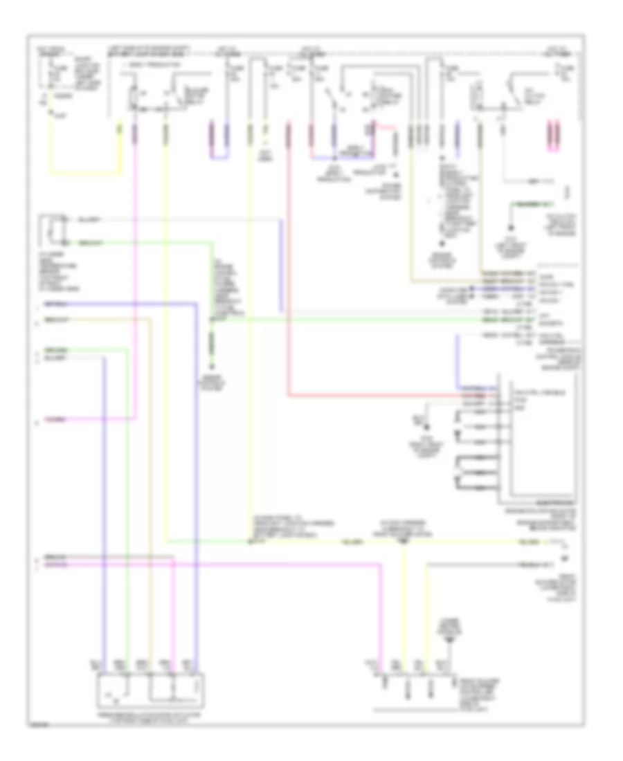
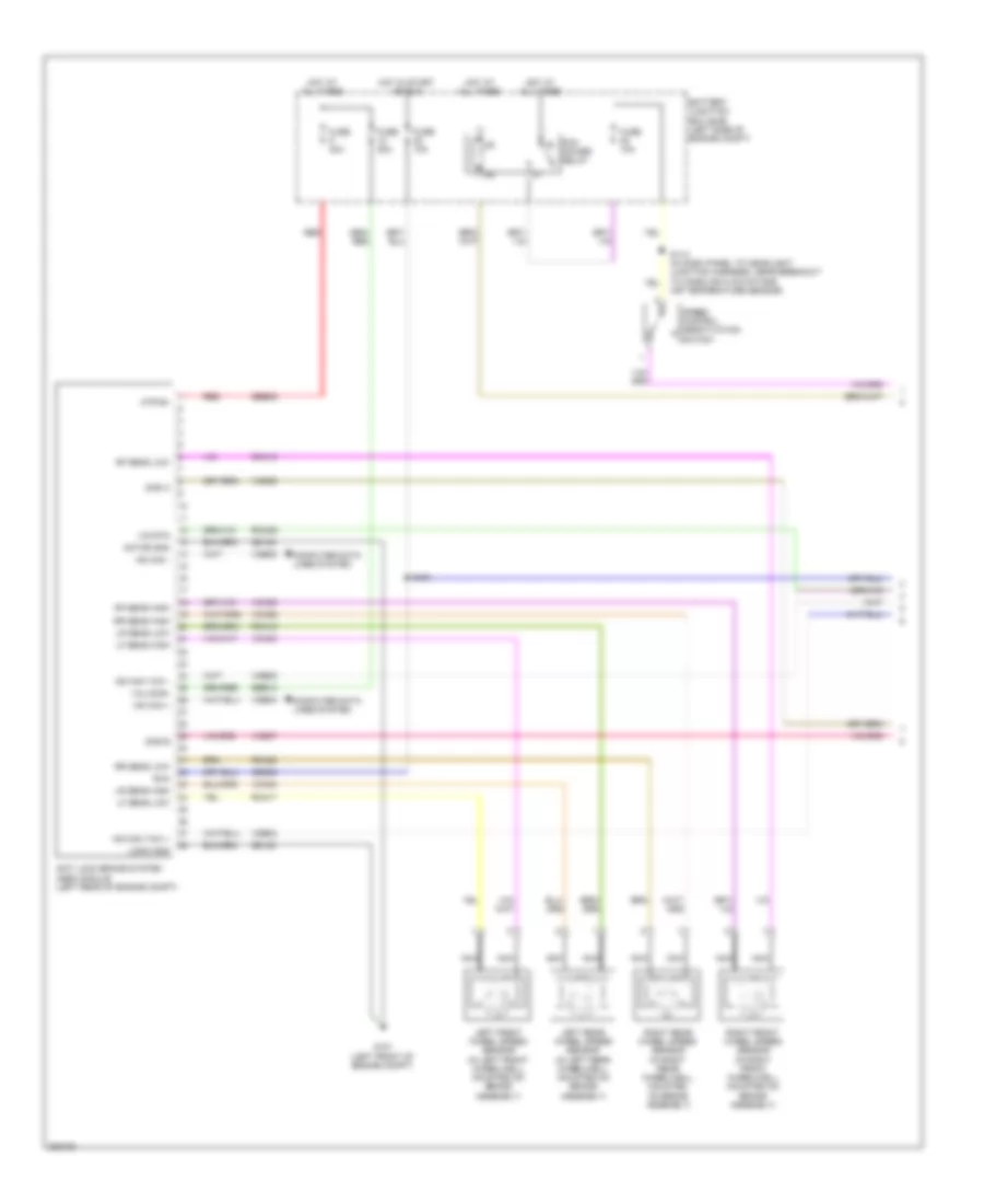
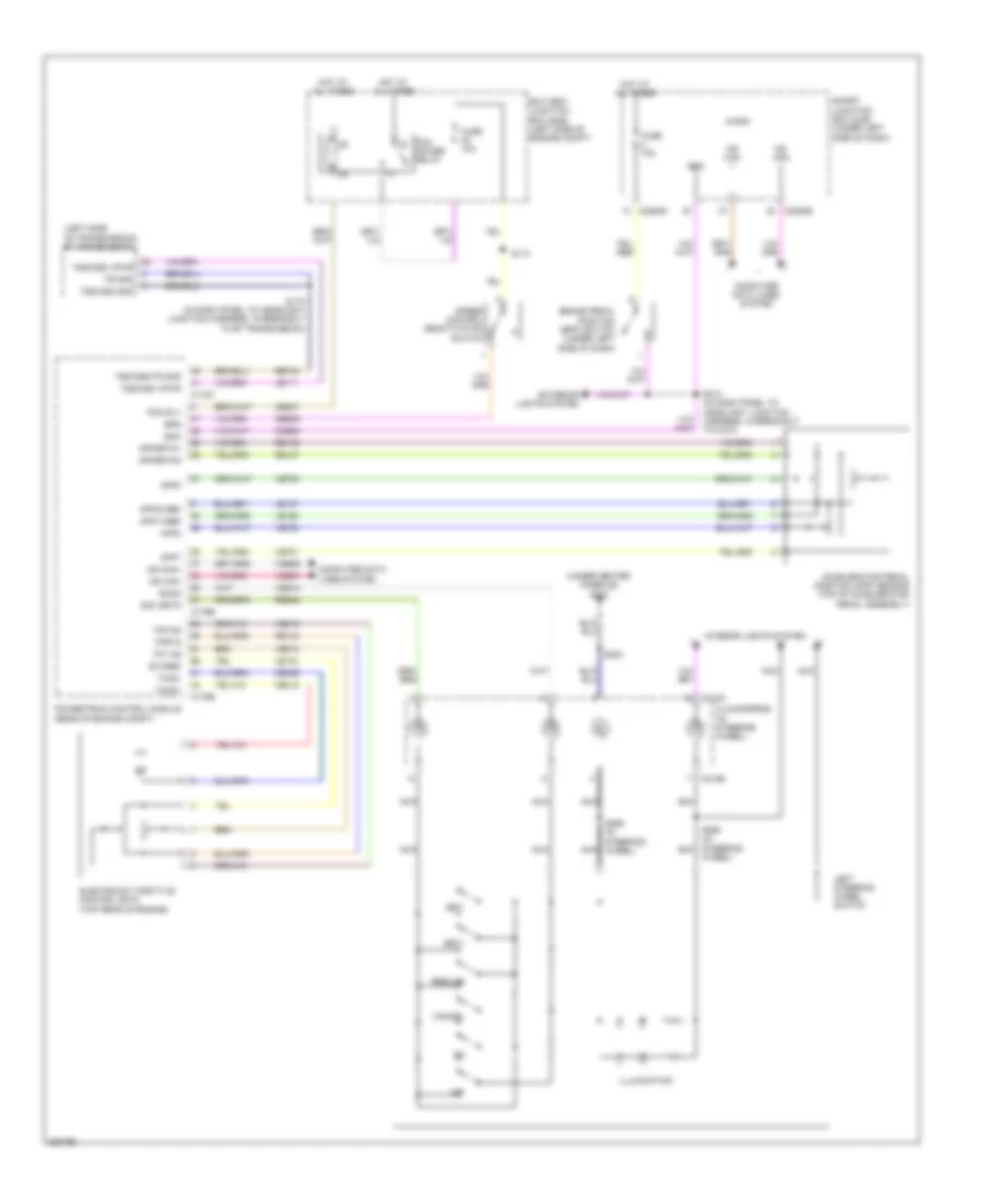
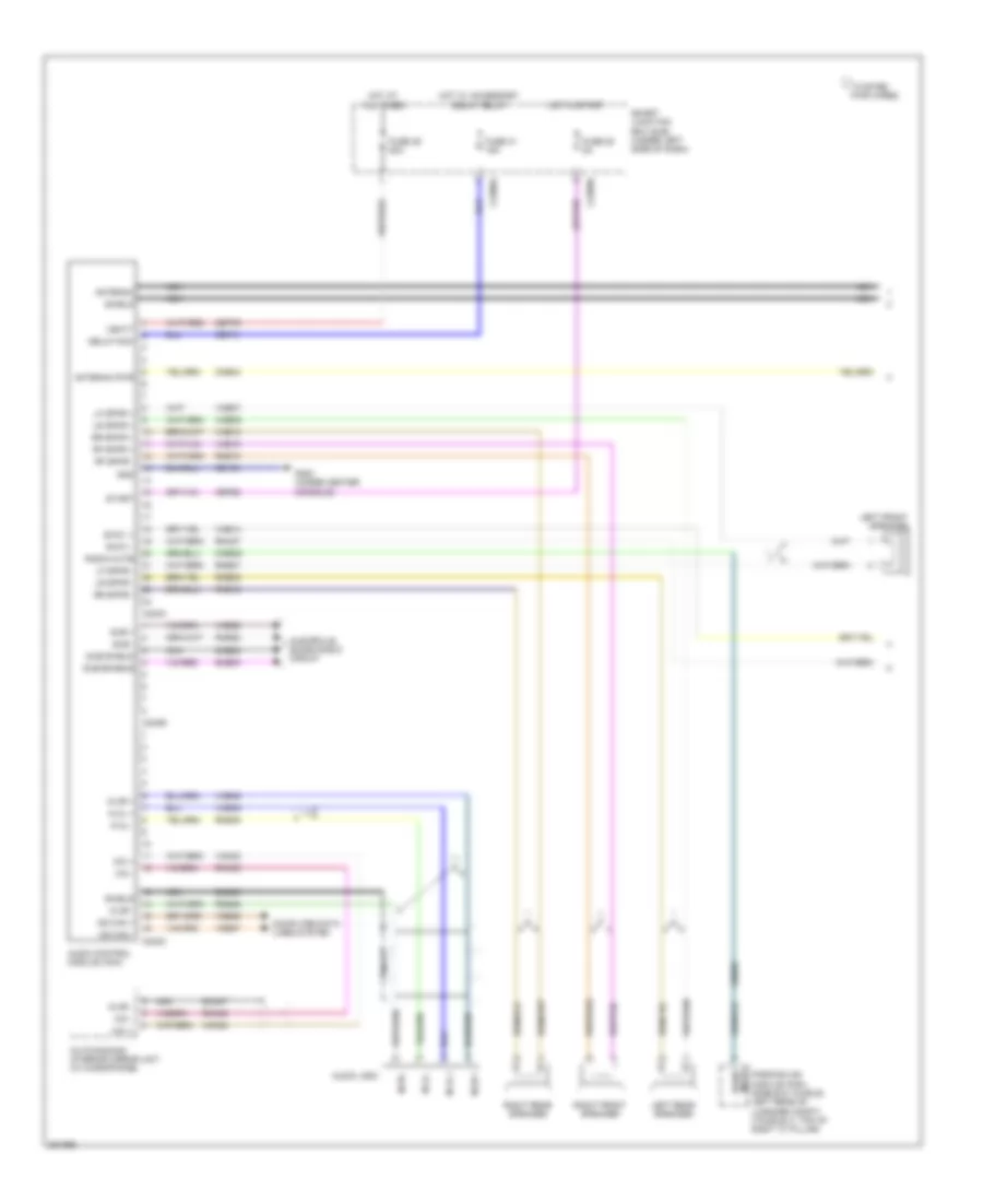
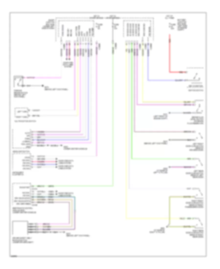
Automatic A/C Wiring Diagram (1 of 2) for Ford Taurus X Limited 2008
 https://portal-diagnostov.com/license.html
Automotive Electricians Portal FZCO
Automotive Electricians Portal FZCO
https://portal-diagnostov.com/license.html
https://portal-diagnostov.com/license.html
Automotive Electricians Portal FZCO
Automotive Electricians Portal FZCO
List of elements for Automatic A/C Wiring Diagram (1 of 2) for Ford Taurus X Limited 2008:
- (behind left center of dash) in-vehicle temperature sensor
- (in dash, above glove box)
- (in main harness, near breakout to passenger air bag module)
- (lower left side of hvac unit) evaporator discharge air temperature sensor
- (under center console)
- Ambient air temperature sensor (behind center of front bumper)
- Ambient temp sens
- Auto- lamp sens in
- Autolamp/sunload sensor
- Aux blwr pot
- Aux blwr spd rly 1
- Aux blwr spd rly 2
- Aux blwr spd rly 3
- Aux mode door act fdbk
- Aux mode door ccw
- Aux mode door cw
- Aux temp door act fdbk
- Aux temp door ccw
- Aux temp door cw
- Aux temp pot
- Auxiliary a/c circuit
- C2280a
- C2280b
- C228a
- C228b
- Cbp37
- Ch112
- Ch113
- Ch114
- Ch122
- Ch123
- Ch207
- Ch208
- Ch212
- Ch213
- Ch228
- Ch229
- Ch238
- Ch239
- Ch242
- Ch243
- Ch244
- Ch245
- Chs04
- Chs09
- Chs13
- Chs14
- Chs29
- Chs30
- Computer data lines system
- Defogger system
- Defrost request
- Driver temperature blend door actuator (left side of hvac unit)
- Drv htd seat hi status
- Drv htd seat lo status
- Drv htd seat req
- Drv sun load
- Drv temp act fdbk
- Drv temp door ccw
- Drv temp door cw
- Evap temp sens
- Front blower rly
- Fuse 10a
- G202
- Gd111
- Gnd
- Hot at all times
- Hot in run or start
- Hvac module (datc) (behind center of dash)
- Incar temp sens
- Lh111
- Mode 1 actr fdbk
- Mode door 1 ccw
- Mode door 1 cw
- Mode door actuator (left side of hvac unit)
- Ms can+
- Ms can-
- Pass htd seat hi status
- Pass htd seat lo status
- Pass htd seat req
- Pass sun load
- Pass temp act fdbk
- Pass temp door ccw
- Pass temp door cw
- Passenger temperature blend door actuator (under right side of dash)
- Recirc act fdbk
- Recirc ccw
- Recirc cw
- Return
- Rh111
- S201
- S202 (in main harness, near breakout to passenger air bag module)
- Sbp15
- Seats system
- Smart junction box (sjb) (under left side of dash)
- Solid state
- Variable blwr ctrl
- Vbatt
- Vdb06
- Vdb07
- Vh101
- Vh406
- Vh407
- Vh411
- Vh414
- Vh416
- Vh417
- Vh436
- Vh438
- Vh440
- Vha09
- Vha15
- Vha17
- Vha18
- Vpwr
- Vref
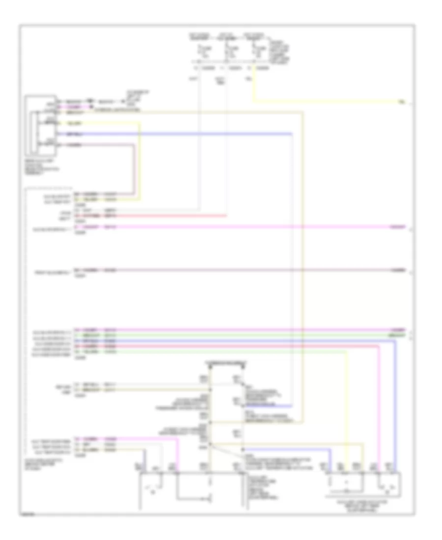
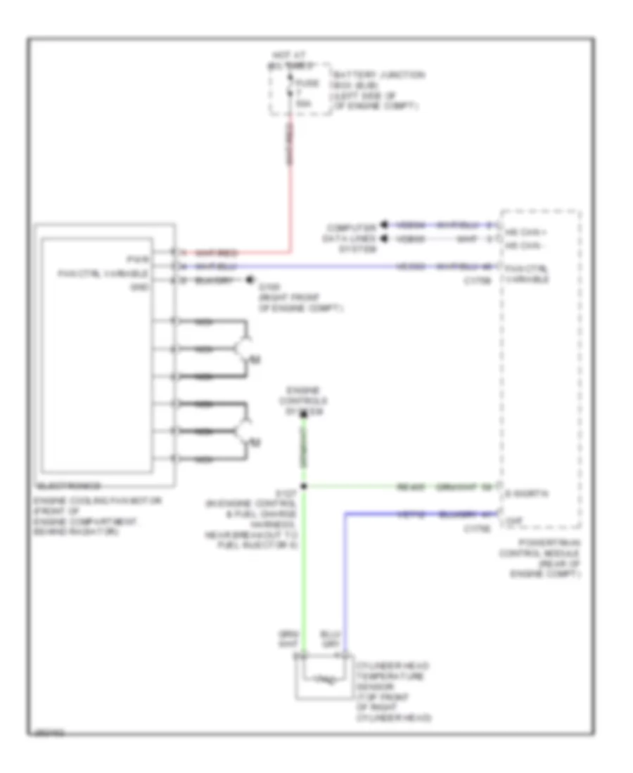
Automatic A/C Wiring Diagram (2 of 2) for Ford Taurus X Limited 2008
List of elements for Automatic A/C Wiring Diagram (2 of 2) for Ford Taurus X Limited 2008:
- (in dash panel to headlight junction harness, near breakout to battery junction box) s140
- (in engine control & fuel charge harness, near breakout to fuel injector 6) s127
- (in main harness, in breakout to front blower motor) s262
- (left side of of engine compt) battery junction box (bjb)
- (not used)
- (under center console) g202
- 10a
- A/c clutch field coil (left front of engine)
- A/c clutch relay
- Accr
- Blower motor relay
- C175b
- C175e
- C2280e
- Ce237
- Ch302
- Cht
- Computer data lines system
- Cylinder head temperature sensor (top front of right cylinder head)
- E-sigrtn
- Early production
- Electronics
- Engine controls system
- Engine cooling fan motor (front of engine compartment, behind radiator)
- Fan ctrl variable
- Fresh/recirculation door actuator (top right side of hvac unit)
- Front blower motor (lower right side of hvac unit)
- Front blower motor speed controller (lower right side of hvac unit)
- Fuse
- Fuse 10a
- Fuse 40a
- Fuse 50a
- Fuse 5a
- G100 (right front of engine compt)
- G101 (left front of engine compt)
- Gnd
- Hot at all times
- Hot in run or acc
- Hs can +
- Hs can -
- Late production
- Motor +
- Motor -
- Nca
- Pcm power relay
- Pcm rly ctrl
- Power distribution system
- Powertrain control module (rear of engine compt)
- Pwm
- Pwr
- Re405
- S141 (early production) (in dash panel to headlight junction harness, near breakout to battery junction box)
- S151 (early production)
- S167
- Smart junction box (sjb) (under left side of dash)
- Vdb04
- Vdb05
- Ve712
- Vec03
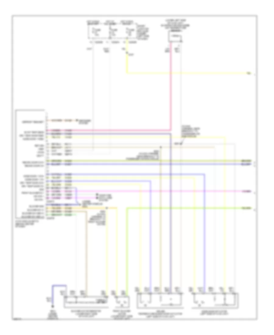
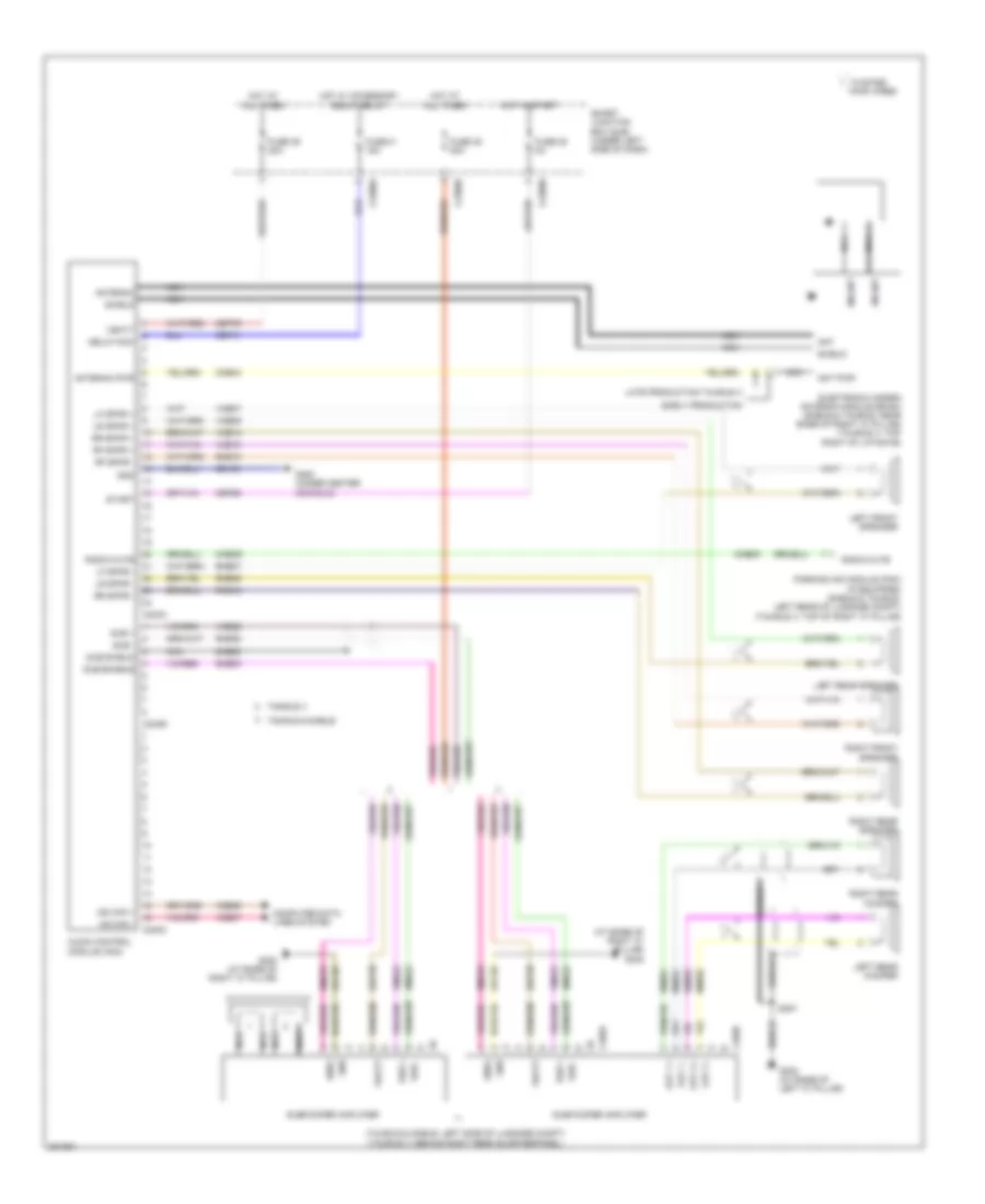
Auxiliary A/C Wiring Diagram (1 of 2) for Ford Taurus X Limited 2008
List of elements for Auxiliary A/C Wiring Diagram (1 of 2) for Ford Taurus X Limited 2008:
- (at base of left "c" pillar) g302
- Automatic a/c circuit
- Aux blower
- Aux blwr pot
- Aux blwr spd rly 1
- Aux blwr spd rly 2
- Aux blwr spd rly 3
- Aux mode door ccw
- Aux mode door cw
- Aux mode door fdbk
- Aux temp
- Aux temp door ccw
- Aux temp door cw
- Aux temp door fdbk
- Aux temp pot
- Auxiliary mode actuator (behind left rear quarterpanel)
- Auxiliary temperature actuator (behind left rear quarterpanel)
- Auxiliary temperature actuator)
- C2280a
- C2280b
- C2280e
- C228a
- C228b
- Cbp37
- Ch112
- Ch113
- Ch114
- Ch123
- Ch242
- Ch243
- Ch244
- Ch245
- Front blower rly
- Fuse 10a
- Fuse 5a
- Gnd
- Hot at all times
- Hot in run or acc
- Hot in run or start
- Hvac module (datc) (behind center of dash)
- Illum
- Interior lights system
- Lh111
- Rear auxiliary function selector switch assembly
- Return
- Rh111
- S201 (in main harness, near breakout to passenger air bag module)
- S202 (in main harness, near breakout to passenger air bag module)
- S319 (in body main harness, near breakout to c3007)
- S392
- S911
- Sbp15
- Smart junction box (sjb) (under left side of dash)
- Vbatt
- Vha09
- Vha15
- Vha17
- Vha18
- Vpwr
- Vref
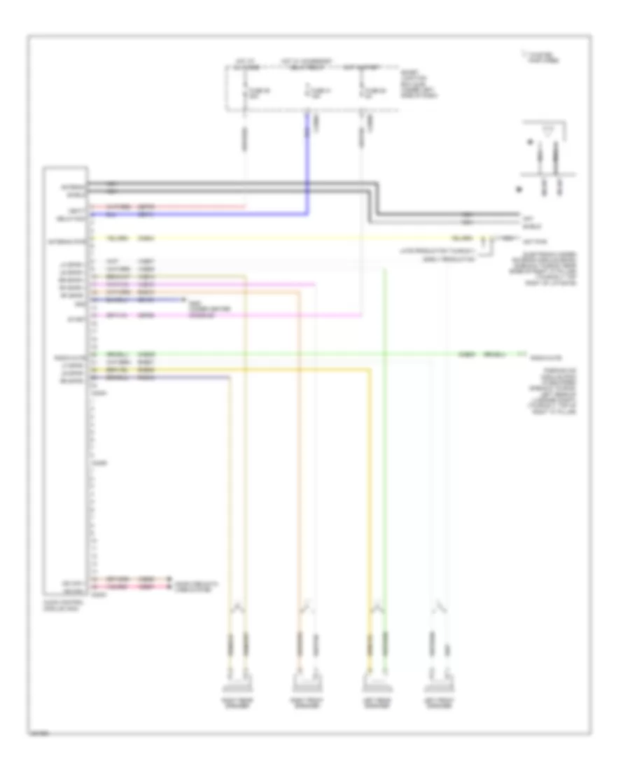
Auxiliary A/C Wiring Diagram (2 of 2) for Ford Taurus X Limited 2008
List of elements for Auxiliary A/C Wiring Diagram (2 of 2) for Ford Taurus X Limited 2008:
- (in air conditioner blower motor harness, in breakout to auxiliary blower motor) s396
- (in air conditioner blower motor harness, near breakout to auxiliary relay box 1) s394
- (in air conditioner blower motor harness, near breakout to auxiliary relay box 1) s395
- (not used)
- Auxiliary blower motor (behind left rear quarterpanel)
- Auxiliary blower motor resistor assembly (left rear corner of vehicle)
- Auxiliary relay box 1 (behind left rear quarterpanel)
- Auxiliary relay box 2 (behind left rear quarterpanel)
- Auxiliary relay box 3 (behind left rear quarterpanel)
- Battery junction box (bjb) (left side of of engine compt)
- Blower motor relay
- Front blower motor (lower right side of hvac unit)
- Front blower motor speed controller (w/ automatic a/c) (lower right side of hvac unit)
- Fuse 30a
- Fuse 40 (early production) 10a
- Fuse 40a
- G302 (at base of left "c" pillar)
- Hot at all times
- S140 (early production) (in dash panel to headlight junction harness, near breakout to battery junction box)
- S167
- S262 (in main harness, in breakout to front blower motor)
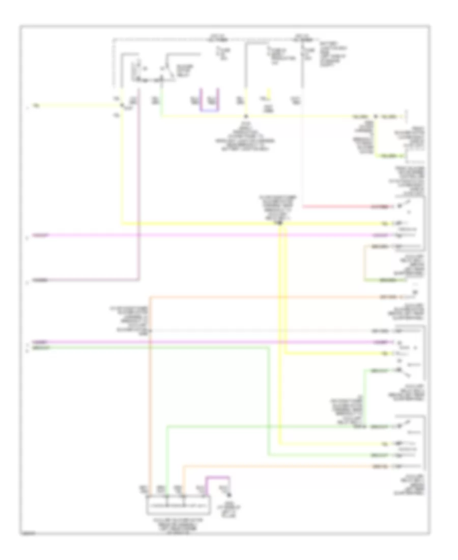
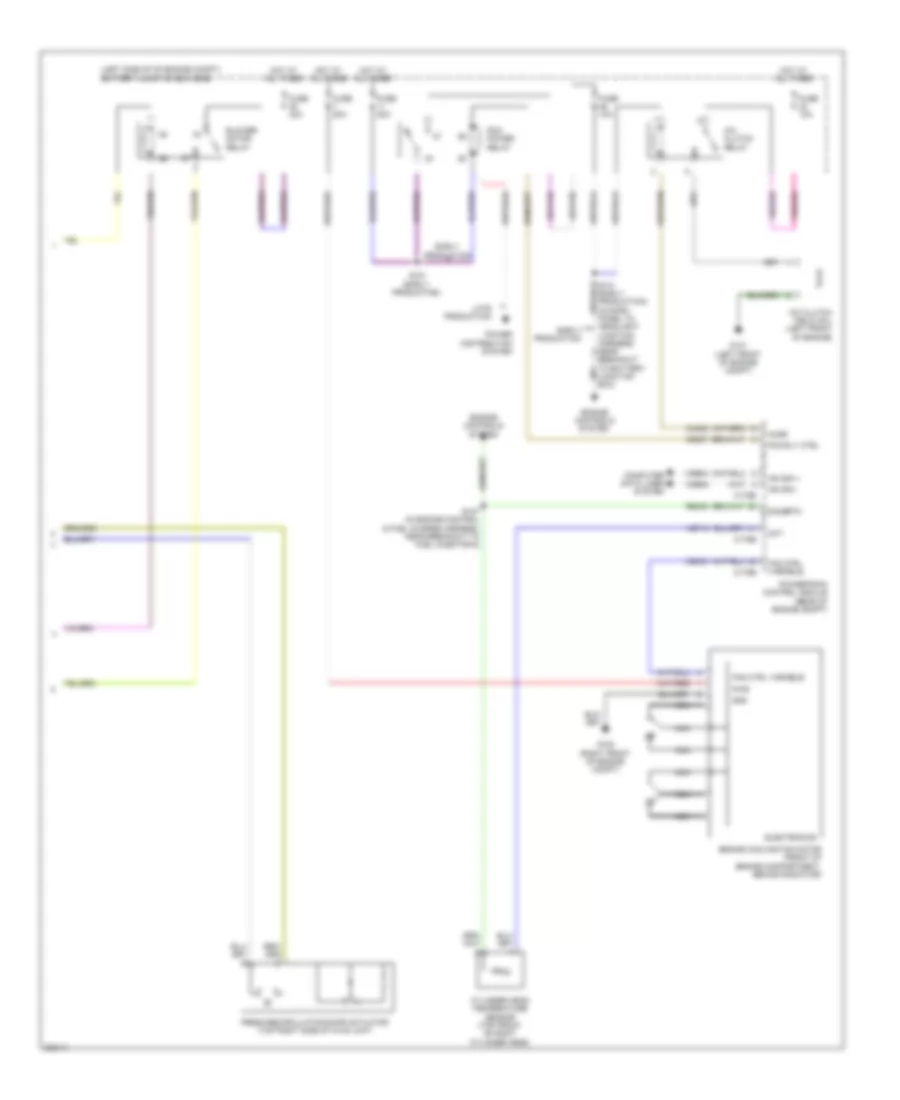
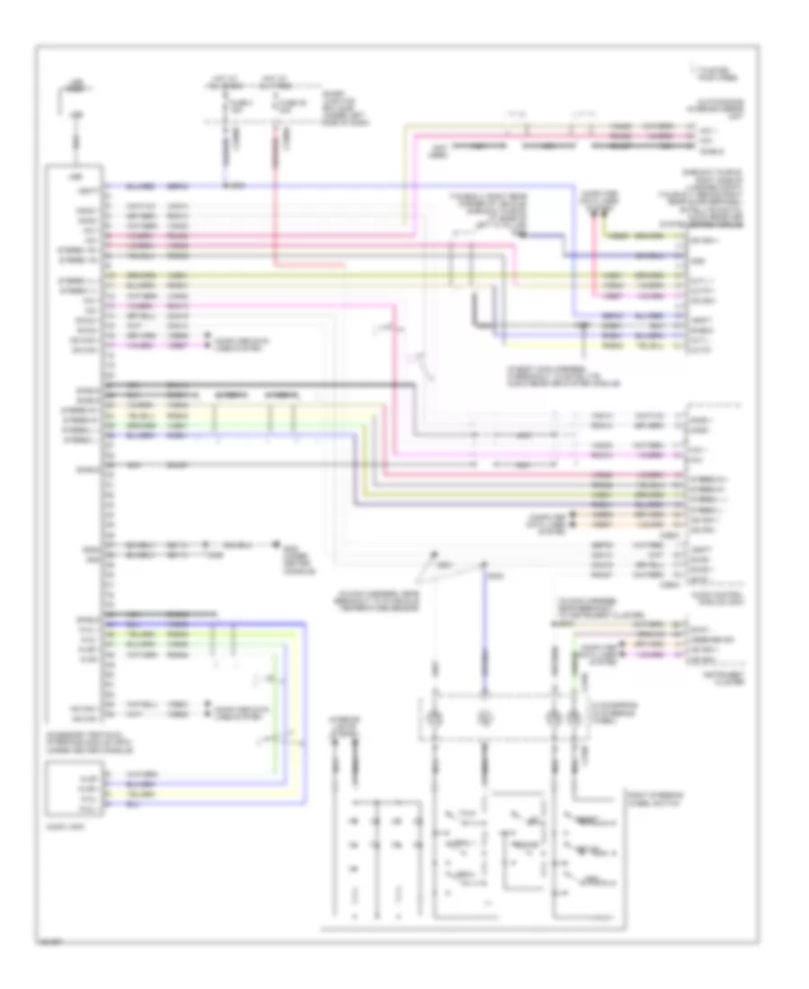
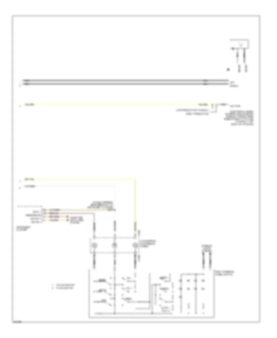
Manual A/C Wiring Diagram (1 of 2) for Ford Taurus X Limited 2008
List of elements for Manual A/C Wiring Diagram (1 of 2) for Ford Taurus X Limited 2008:
- (in main harness, near breakout to passenger air bag module)
- (lower left side of hvac unit) evaporator discharge air temperature sensor
- (under center console) g202
- Blower gnd
- Blower motor resistor (lower right side of hvac unit)
- Blower sw hi
- Blower sw med hi
- Blower sw med lo
- C2280a
- C2280b
- C2280e
- C2357a
- C2357b
- Cbp37
- Ch122
- Ch123
- Ch207
- Ch208
- Ch228
- Ch229
- Ch238
- Ch239
- Ch426
- Ch428
- Ch429
- Computer data lines system
- Defogger system
- Defrost request
- Driver temperature blend door actuator (left side of hvac unit)
- Drv temp door ccw
- Drv temp door cw
- Drv temp door fdbk
- Evap temp sens
- Front blower motor (lower right side of hvac unit)
- Front blower rly
- Fuse 10a
- Fuse 5a
- G202 (under center console)
- Gd111
- Gnd
- Hot at all times
- Hot in run or acc
- Hot in run or start
- Hvac module (emtc) (behind center of dash)
- Lh111
- Mode door 1 ccw
- Mode door 1 cw
- Mode door 1 fdbk
- Mode door actuator (left side of hvac unit)
- Ms can +
- Ms can -
- Recirc door cw
- Recirc door cww
- Return
- Rh111
- S167
- S201
- S202 (in main harness, near breakout to passenger air bag module)
- S263 (in main harness, in breakout to front blower motor)
- Sbp15
- Smart junction box (sjb) (under left side of dash)
- Thermal limiter
- Vbatt
- Vdb06
- Vdb07
- Vh406
- Vh436
- Vh440
- Vpwr
- Vref
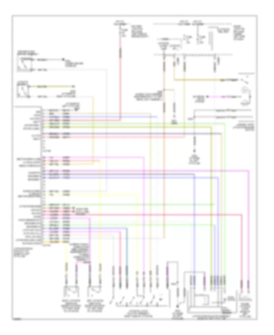
Manual A/C Wiring Diagram (2 of 2) for Ford Taurus X Limited 2008
List of elements for Manual A/C Wiring Diagram (2 of 2) for Ford Taurus X Limited 2008:
- (left side of of engine compt) battery junction box (bjb)
- A/c clutch field coil (left front of engine)
- A/c clutch relay
- Accr
- Blower motor relay
- C175b
- C175e
- Ce237
- Ch302
- Cht
- Computer data lines system
- Cylinder head temperature sensor (top front of right cylinder head)
- E-sigrtn
- Early production
- Electronics
- Engine controls system
- Engine cooling fan motor (front of engine compartment, behind radiator)
- Fan ctrl variable
- Fresh/recirculation door actuator (top right side of hvac unit)
- Fuse 10a
- Fuse 40a
- Fuse 50a
- G100 (right front of engine compt)
- G101 (left front of engine compt)
- Gnd
- Hot at all times
- Hs can +
- Hs can -
- Late production
- Nca
- Pcm power relay
- Pcm rly ctrl
- Power distribution system
- Powertrain control module (rear of engine compt)
- Pwr
- Re405
- S127 (in engine control & fuel charge harness, near breakout to fuel injector 6)
- S141 (early production) (in dash panel to headlight junction harness, near breakout to battery junction box)
- S151 (early production)
- Vdb04
- Vdb05
- Ve712
- Vec03
ANTI-LOCK BRAKES
Anti-lock Brakes Wiring Diagram (1 of 2) for Ford Taurus X Limited 2008
List of elements for Anti-lock Brakes Wiring Diagram (1 of 2) for Ford Taurus X Limited 2008:
- Anti lock brake system (abs) module (left rear of engine compt)
- Battery junction box (bjb) (left side of engine compt)
- Cbb38
- Computer data lines system
- Fuse 10a
- Fuse 20a
- Fuse 40a
- G101 (left front of engine compt)
- Gd120
- Hot at all times
- Hot in start or run
- Hs can +
- Hs can -
- Hs can yaw +
- Hs can yaw -
- Ivd rtn
- Left front wheel speed sensor (in left front wheelwell, mounted on brake assembly)
- Left rear wheel speed sensor (in left rear wheelwell, mounted on brake assembly)
- Lf sens high
- Lf sens low
- Logic gnd
- Lr sens high
- Lr sens low
- Motor gnd
- Mtr b+
- Nca
- Pcm power relay
- Rca09
- Rca17
- Rca18
- Rca19
- Rca20
- Red
- Rf sens high
- Rf sens low
- Right front wheel speed sensor (in right front wheelwell, mounted on brake assembly)
- Right rear wheel speed sensor (in right rear wheelwell, mounted on brake assembly)
- Rr sens high
- Rr sens low
- Run
- S113 (in dash panel to headlight junction harness, near breakout to mass air flow/intake air temperature sensor)
- S164
- Sas a
- Sas b
- Sbb09
- Sbb12
- Speed control deactivation switch
- Valve b+
- Vca03
- Vca04
- Vca05
- Vca06
- Vcs06
- Vcs07
- Vdb04
- Vdb05
Anti-lock Brakes Wiring Diagram (2 of 2) for Ford Taurus X Limited 2008
List of elements for Anti-lock Brakes Wiring Diagram (2 of 2) for Ford Taurus X Limited 2008:
- (in dash panel to headlight junction harness, in breakout to c210) s213
- (not used)
- (top of steering module) (w/ traction) steering angle sensor module (sasm)
- (under center console) (w/ traction) stability control sensor cluster
- Boo
- Bps
- Brake pedal position (bpp) switch (under left side of dash)
- C175b
- C2280b
- C2280d
- C4174a
- Cbb38
- Ccb08
- Ce237
- Center stack switch assembly
- Ces09
- Cmp02
- Cmp18
- Computer data lines system
- Console open/ close sw
- Cpr63
- Enable/disable
- Exterior lights system
- Fuse 15a
- G202 (under center console)
- Hazard
- Hot at all times
- Instrument cluster (ic)
- Interior lights system
- Ivd ind
- Ivd sw
- Liftgate
- Liftgate/trunk module (ltm) (base of left "d" pillar)
- Micro
- Ms can +
- Ms can -
- Parking aid
- Parking aid module (pam) (sable & taurus: left rear of luggage compt) (taurus x: top of right "c" pillar)
- Pcm rly ctrl
- Powertrain control module (rear of engine compt)
- Rca09
- S219 (in main harness, near breakout to instrument cluster)
- S261
- Smart junction box (sjb) (under left side of dash)
- Solid state
- Status led
- Traction control on/off
- Vcs06
- Vcs07
ANTI-THEFT
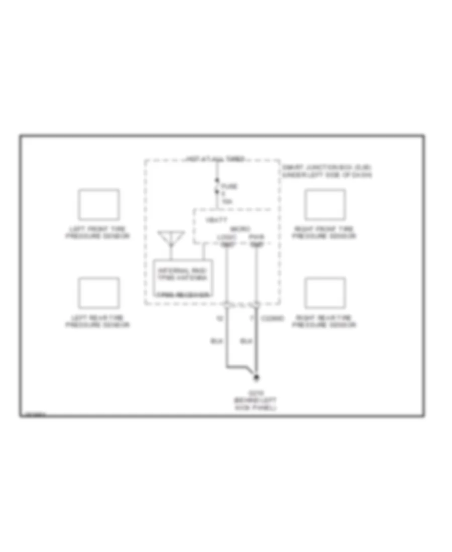
Forced Entry Wiring Diagram (1 of 2) for Ford Taurus X Limited 2008
List of elements for Forced Entry Wiring Diagram (1 of 2) for Ford Taurus X Limited 2008:
- (behind left kick panel) g210
- (in body main harness, near breakout to c311) s330
- 1/2
- 3/4
- 5/6
- 7/8
- 9/0
- All lock/ unlock relay
- Antenna rke receiver
- C2280c
- C2280d
- Driver door unlock relay
- Fuse 20a
- G210 (behind left kick panel)
- G302 (at base of left "c" pillar)
- Hot at all times
- Interior lights system
- Internal rke/tpms
- Keypad switch assembly
- Left front door lock actuator (rear of driver's door)
- Left rear door lock actuator (rear of left rear door)
- Liftgate lock actuator (right side of liftgate)
- Liftgate rel (fet)
- Liftgate/glass ajar
- Micro
- Nca
- Right front door lock actuator (rear of front passenger's door)
- Right rear door lock actuator (rear of right rear door)
- S331 (in body main harness, near breakout to c311)
- S400
- S500
- Smart junction box (sjb) (under left side of dash)
Forced Entry Wiring Diagram (2 of 2) for Ford Taurus X Limited 2008
List of elements for Forced Entry Wiring Diagram (2 of 2) for Ford Taurus X Limited 2008:
- (in body main harness, near breakout to c925) s324
- Accessory delay relay
- Anti-theft
- Anti-theft hood switch (at left front corner of engine compt)
- C2280c
- C2280d
- C2280f
- Dr reset sw
- Driver door disarm switch
- Driver side door lock switch
- Fuse 15a
- G101 (left front of engine compt)
- G210 (behind left kick panel)
- G300 (taurus x) g305 (sable & taurus) (at base of right "c" pillar)
- G302 (at base of left "c" pillar)
- Hot at all times
- Left front door ajar switch (rear of driver's door)
- Left rear door ajar switch (rear of left rear door)
- Lf dr ajar
- Lock
- Lr dr ajar
- Micro
- Passenger side door lock switch
- Power windows system
- Rf dr ajar
- Right front door ajar switch (rear front of passenger's door)
- Right rear door ajar switch (rear of right rear door)
- Rr dr ajar
- S318
- S327 (in body main harness, near breakout to c925)
- S500
- S502
- S503
- S600
- Smart junction box (sjb) (under left side of dash)
- Trim lock
- Trim unlock
- Unlock
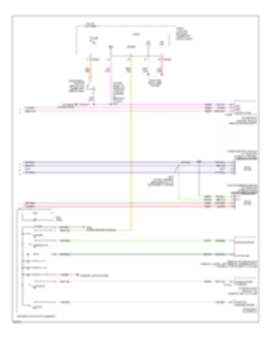
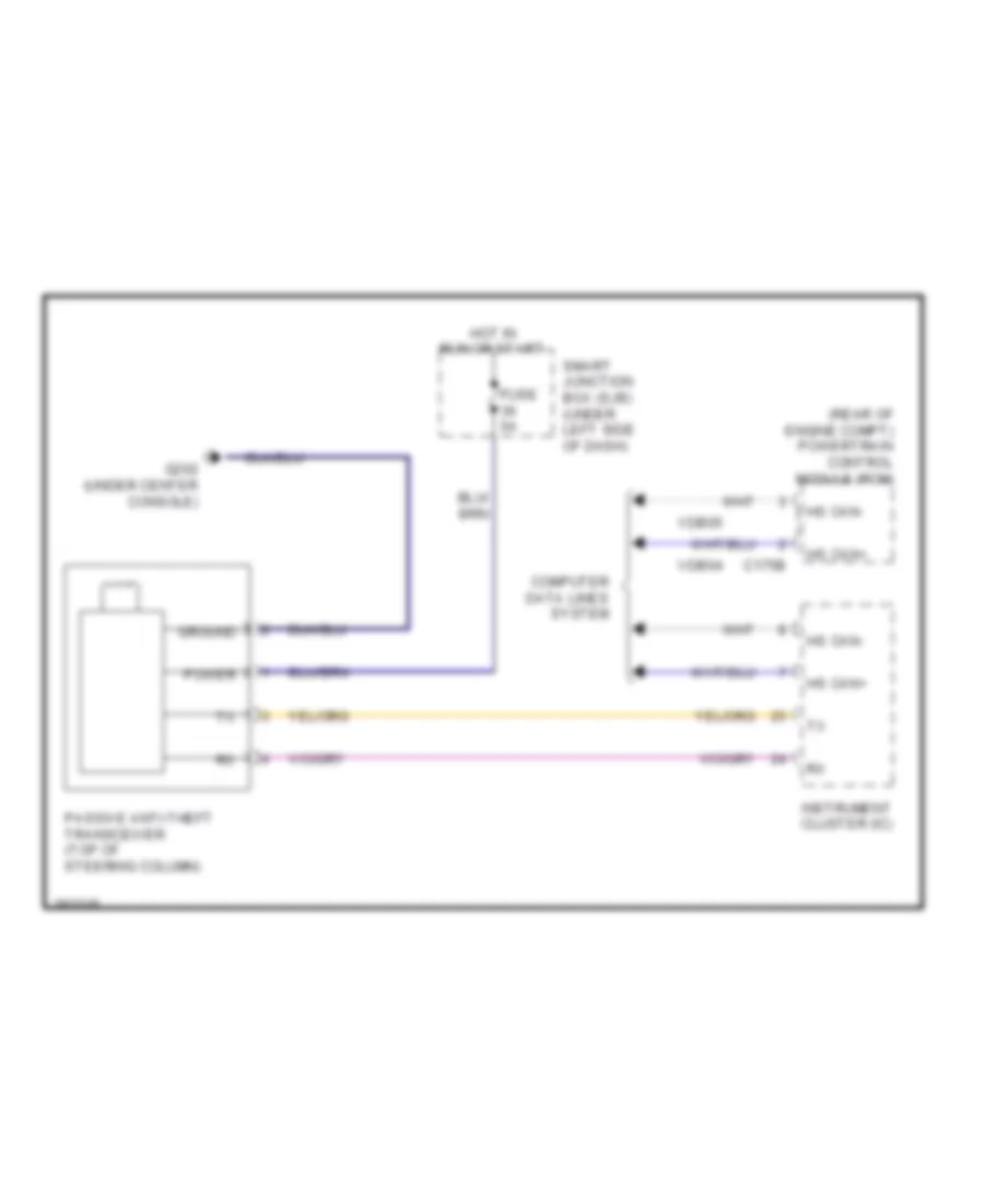
Passive Anti-theft Wiring Diagram for Ford Taurus X Limited 2008
List of elements for Passive Anti-theft Wiring Diagram for Ford Taurus X Limited 2008:
- (rear of engine compt) powertrain control module (pcm)
- C175b
- Computer data lines system
- Fuse 5a
- G202 (under center console)
- Ground
- Hot in run or start
- Hs can+
- Hs can-
- Instrument cluster (ic)
- Passive anti-theft transceiver (top of steering column)
- Power
- Smart junction box (sjb) (under left side of dash)
- Vdb04
- Vdb05
BODY CONTROL MODULES
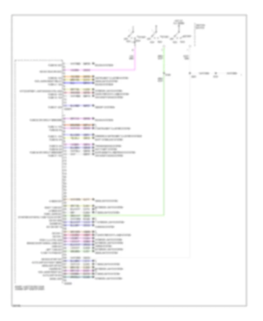
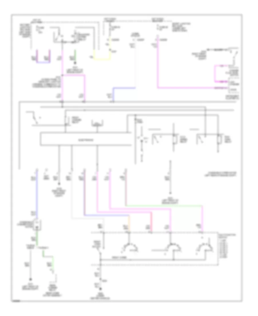
Body Control Modules Wiring Diagram (1 of 2) for Ford Taurus X Limited 2008
List of elements for Body Control Modules Wiring Diagram (1 of 2) for Ford Taurus X Limited 2008:
- Acc
- Air conditioning system
- Anti-theft system
- Autolamp day/night sens
- Autolamp on sw
- Brake on/off normal open sw
- C2280a
- C2280b
- Cbp28
- Cbp29
- Cbp30
- Cbp31
- Cbp34
- Cbp36
- Cbp37
- Cbp41
- Cbp46
- Ccb08
- Cdc30
- Cdc33
- Cdc34
- Ce336
- Clf12
- Clf17
- Clf18
- Clf19
- Clf21
- Clf23
- Clf27
- Cln28
- Cls32
- Cls34
- Cls39
- Cls41
- Computer data lines system
- Crh02
- Dim sw gnd
- Dimmer sw
- Dome lamp
- Exterior lights system
- Flash to pass sw
- Fog lamps front relay
- Fog lamps front sw
- Fuse 14, 10a
- Fuse 15, 10a
- Fuse 20, 15a
- Fuse 26, 10a
- Fuse 27, 20a
- Fuse 28 or circuit breaker
- Fuse 29, 5a
- Fuse 30, 5a
- Fuse 31, 10a
- Fuse 34, 5a
- Fuse 36, 5a
- Fuse 37, 10a
- Fuse 39, 20a
- Fuse 41, 15a
- Fuse 46 or circuit breaker
- Hazard sw
- Headlamp off sw
- Headlights system
- Hi beam sw
- Horn sw
- Horns system
- Hot at all times
- Ign run start sw
- Ign sw (run or acc)
- Ignition switch
- Instrument cluster system
- Int/courtesy lamp dimming ctrl mod
- Interior lights system
- Ip/sw illu ctrl mod
- Left turn sw
- Lo beam sw
- Memory systems
- Mirrors & instrument cluster systems
- Ms can +
- Ms can -
- Off
- Park lamps sw
- Right turn sw
- Rln29
- Run
- S161
- S169
- S221
- Sbp14
- Sbp15
- Sbp20
- Sbp26
- Sbp27
- Sbp39
- Shift interlock system
- Smart junction box (sjb) (under left side of dash)
- Sound systems
- Start
- Starter motor rly one touch start
- Sw ign key in
- Transmissions system
- Vdb06
- Vdb07
- Vlf14
- Vln04
- Vln18
- Vln33
- Warning system
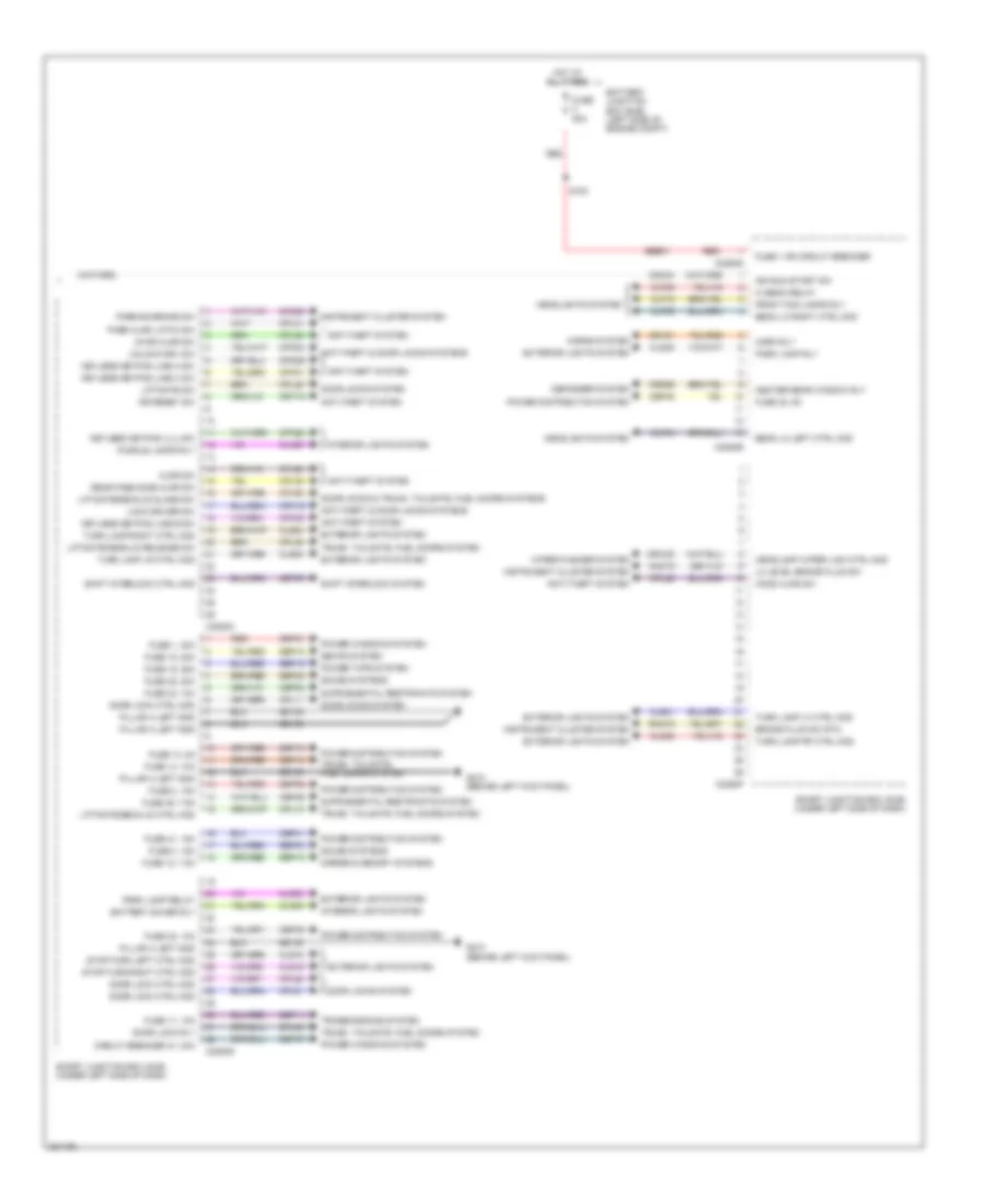
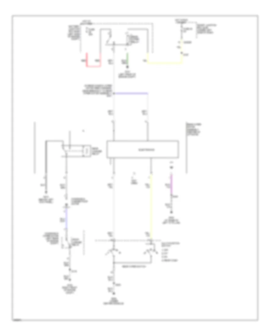
Body Control Modules Wiring Diagram (2 of 2) for Ford Taurus X Limited 2008
List of elements for Body Control Modules Wiring Diagram (2 of 2) for Ford Taurus X Limited 2008:
- Ajar sw
- Anti-theft & door locks systems
- Anti-theft system
- Battery junction box (bjb) (left side of engine compt)
- Battery saver rly
- Beam lo left ctrl mod
- Beam lo right ctrl mod
- Brake fluid sw rtn
- C2280c
- C2280d
- C2280e
- C2280f
- C2280g
- Cbp32
- Cbp35
- Cbp41
- Cbp45
- Cbp46
- Cbp47
- Cdc34
- Cet53
- Circuit breaker 47, 30a
- Clf04
- Clf05
- Clf08
- Clf12
- Cln09
- Cln25
- Cls18
- Cls19
- Cls21
- Cls23
- Cls24
- Cls25
- Cls30
- Cmc19
- Cmc25
- Cpk19
- Cpk23
- Cpk28
- Cpk29
- Cpk30
- Cpk31
- Cpl10
- Cpl11
- Cpl25
- Cpl26
- Cpl31
- Cpl36
- Cpl39
- Cpl45
- Cpl51
- Cpl52
- Cpl58
- Cpl59
- Crd06
- Crt19
- Crw22
- Defogger system
- Door lock ctrl mod
- Door lock rly
- Door locks & trunk, tailgate, fuel doors systems
- Door locks system
- Dr reset sw
- Exterior lights system
- Front fog lamps rly
- Fuse 1 or circuit breaker
- Fuse 1, 30a
- Fuse 11, 10a
- Fuse 12, 7.5a
- Fuse 13, 5a
- Fuse 14, 10a
- Fuse 18, 20a
- Fuse 19, 25a
- Fuse 2, 15a
- Fuse 3, 15a
- Fuse 32, 10a
- Fuse 35, 10a
- Fuse 38, 20a
- Fuse 41, 15a
- Fuse 45, 5a
- Fuse 46, 7.5a
- Fuse 80a
- G210 (behind left kick panel)
- Gd133
- Headlamp wiper link ctrl mod
- Headlights system
- Heater rear window rly
- Hi beam relay
- Hood ajar sw
- Horn rly
- Horns system
- Hot at all times
- Ign run start sw
- Instrument cluster system
- Interior lights system
- Keyless keypad illu sw
- Keyless keypad line a sw
- Keyless keypad line b sw
- Keyless keypad line c sw
- Liftgate sw
- Liftgate/decklid ctrl mod
- Liftgate/decklid glass sw
- Liftgate/decklid release sw
- Lo level brake fluid sw
- Lock driver sw
- Lr dr ajar sw
- Mirror & memory systems
- Park lamp relay
- Park lamp rly
- Parking brake sw
- Pass ajar latch sw
- Pillar a left gnd
- Power distribution system
- Power tops system
- Power windows system
- Puddle lamps rly
- Rear pass side ajar sw
- Red
- Rmc19
- S183
- Sbb01
- Sbp01
- Sbp02
- Sbp03
- Sbp11
- Sbp12
- Sbp13
- Sbp14
- Sbp18
- Sbp19
- Sbp38
- Seats system
- Shift interlock ctrl mod
- Shift interlock system
- Smart junction box (sjb) (under left side of dash)
- Sound systems
- Srh01
- Stop/turn left ctrl mod
- Stop/turn right ctrl mod
- Transmissions system
- Trunk, tailgate, fuel doors system
- Turn lamp lf ctrl mod
- Turn lamp lr ctrl mod
- Turn lamp rf ctrl mod
- Turn lamp right ctrl mod
- Unlock drv sw
- Wiper/washer system
COMPUTER DATA LINES
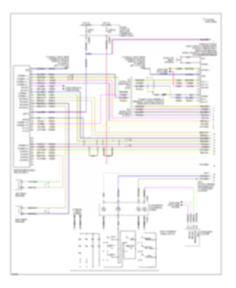
Computer Data Lines Wiring Diagram for Ford Taurus X Limited 2008
List of elements for Computer Data Lines Wiring Diagram for Ford Taurus X Limited 2008:
- 'd' pillar)
- (behind center of dash) (if equipped) hvac module emtc
- (behind right kick panel) power steering control module
- (center front of roof)
- (in body main harness, in breakout to satellite digital audio receiver system module)
- (in body main harness, near breakout to c312) s371
- (in body main harness, near breakout to c312) s372
- (in body main harness, near breakout to c3133) s370
- (in body main harness, near breakout to c328)
- (in body main harness, near breakout to c328) s300
- (in body main harness, near breakout to restraints control module) s309
- (in body main harness, near breakout to satellite digital audio receiver system module)
- (in interior lights harness, near breakout to c9092)
- (in main harness, near breakout to
- (in main harness, near breakout to instrument cluster)
- (in main harness, near breakout to instrument cluster) s209
- (mounted on dash, below steering column)
- (rear of engine compt)
- (sable & taurus: in interior lights harness, near breakout to c9092)
- (under center console)
- (under driver's seat)
- (under front
- (w/ satellite radio) (sable & taurus: right side of luggage compartment) (taurus x: behind right rear quarterpanel)
- Accessory protocol interface module (sync)
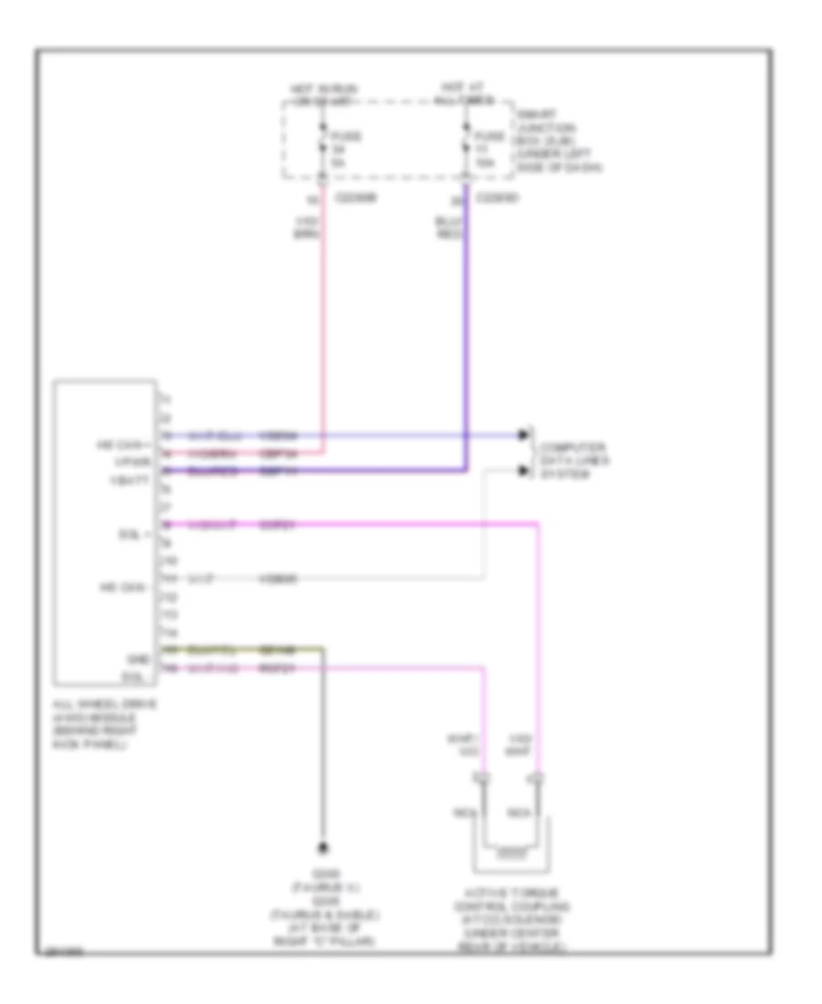
- All wheel drive (awd) module (if equipped) (left front of engine compartment, below battery)
- Anti-lock brake system module (abs) (left rear of engine compt)
- Audio control module
- Autolamp/sunload sensor)
- Autolamp/sunload sensor) s204
- C175b
- C2280a
- C2280b
- C228a
- C2357a
- C2368a
- C240c
- C310b
- C341d
- C4174a
- Can+
- Cdb08
- Data link connector (dlc)
- Driver seat module (dsm) (w/ memory)
- Feps
- Fuse 15a
- G202
- Gd111
- Havc module datc (if equipped) (behind center of dash)
- Hot at all times
- Hs can+
- Hs can-
- Instrument cluster
- Iso
- Lift gate trunk module (w/ power liftgate) (base of left
- Micro
- Ms can+
- Ms can-
- Occupant classification system module
- Parking aid module (taurus x: top of right 'c' pillar) (sable & taurus: left rear of luggage compt)
- Passenger's seat)
- Powertrain control module
- Rear entertainment module (retm) (w/ dvd rear entertainment center)
- Restraints control module
- S115 (in dash panel to headlight junction harness, near breakout to anti-lock brake system module)
- S205
- S208
- S223
- S301
- S302
- S303
- S306
- S367
- S402
- S403
- S905 (taurus x: in inside rearview mirror harness,near breakout to lift vanity mirrior light)
- S906
- Satellite digital audio receiver system (sdars) module
- Sbp20
- Smart junction box (sjb) (under left side of dash)
- Vdb04
- Vdb05
- Vdb06
- Vdb07
- Vdb10
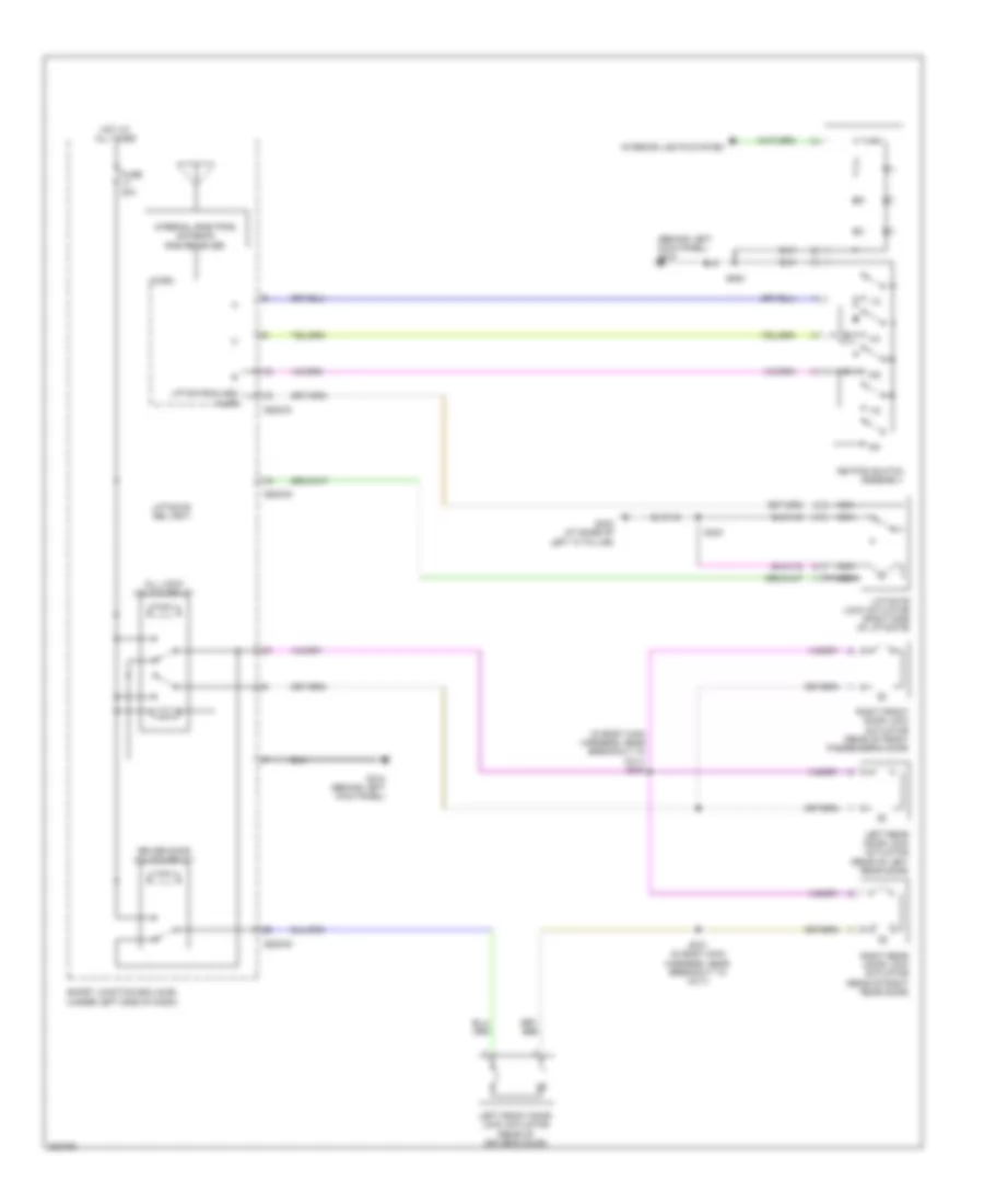
COOLING FAN
Cooling Fan Wiring Diagram for Ford Taurus X Limited 2008
List of elements for Cooling Fan Wiring Diagram for Ford Taurus X Limited 2008:
- Battery junction box (bjb) (left side of of engine compt)
- C175b
- C175e
- Cht
- Computer data lines system
- Cylinder head temperature sensor (top front of right cylinder head)
- E-sigrtn
- Electronics
- Engine controls system
- Engine cooling fan motor (front of engine compartment, behind radiator)
- Fan ctrl variable
- Fuse 50a
- G100 (right front of engine compt)
- Gnd
- Hot at all times
- Hs can +
- Hs can -
- Nca
- Powertrain control module (rear of engine compt)
- Pwr
- Re405
- S127 (in engine control & fuel charge harness, near breakout to fuel injector 6)
- Vdb04
- Vdb05
- Ve712
- Vec03
CRUISE CONTROL
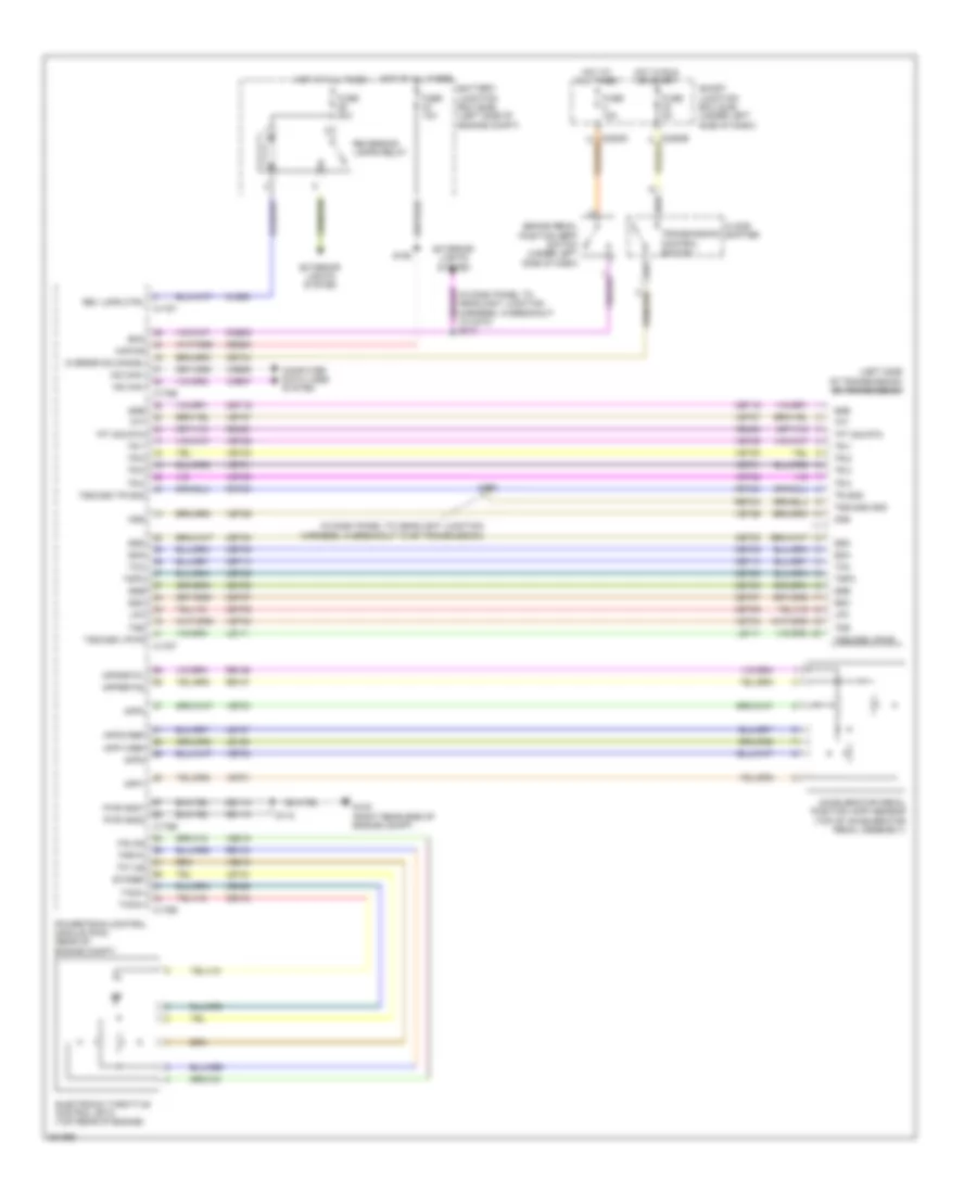
Cruise Control Wiring Diagram for Ford Taurus X Limited 2008
List of elements for Cruise Control Wiring Diagram for Ford Taurus X Limited 2008:
- (left side of transmission) 6f transmission
- (under center console) g202
- Accelerator pedal position (app) sensor (top of accelerator pedal assembly)
- App1
- App1vref
- App2
- App2vref
- App3
- Appsrtn1
- Appsrtn2
- Battery junction box (bjb) (left side of engine compt)
- Boo
- Bps
- Brake pedal position (bpp) switch (under left side of dash)
- C175b
- C175e
- C175t
- C218a
- C218b
- C2280b
- C2280d
- Cancel
- Ccb08
- Ce237
- Ce412
- Ce426
- Ces09
- Clockspring (in steering wheel)
- Computer data lines system
- Electronic throttle control (etc) (top rear of engine)
- Etcref
- Exterior lights system
- Fuse 10a
- Fuse 15a
- Hot at all times
- Illumination
- Interior lights system
- Le111
- Le134
- Le136
- Le137
- Left steering wheel switch
- Micro
- Ms can +
- Ms can -
- Ms can+
- Ms can-
- Nca
- Off
- Pcm power relay
- Pcm rly
- Powertrain control module (rear of engine compt)
- Re134
- Re136
- Re137
- Res08
- Resume
- Ret24
- S113
- S173 (in dash panel to headlight junction harness, in breakout to 6f transmission)
- S213 (in dash panel to headlight junction harness, in breakout to c210)
- S223
- S298 (in steering nca
- S299 (in steering wheel)
- Scc srtn
- Sccs
- Set+
- Set-
- Smart junction box (sjb) (under left side of dash)
- Speed control deactivation switch
- Tacm+
- Tacm-
- Tp1 ns
- Tp2 ps
- Tprtn
- Tr gnd
- Tss/oss gnd
- Tss/oss vpwr
- Tss/oss/tr gnd
- Vdb06
- Vdb07
- Ve701
- Ve702
- Ve703
- Ve818
- Ve819
- Ves10
- Wheel)
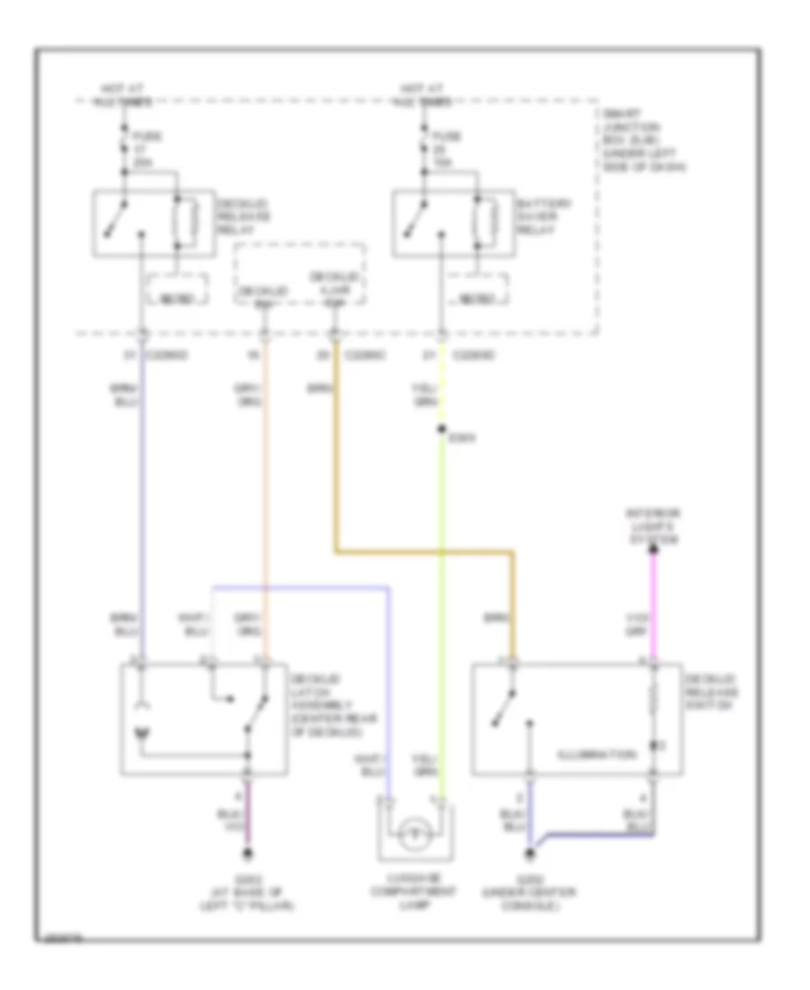
DEFOGGERS
Defoggers Wiring Diagram for Ford Taurus X Limited 2008
List of elements for Defoggers Wiring Diagram for Ford Taurus X Limited 2008:
- (not used)
- Automatic a/c
- Battery junction box (bjb) (left side of engine compt)
- C2280a
- C2280b
- C2280e
- C228b
- C2357a
- C402a
- C402b
- Defrost request
- Early production
- Fuse 10a
- Fuse 15a
- Fuse 40a
- Fuse 5a
- G202 (under center console)
- G300 (taurus x) (at base of right ``c" pillar)
- G302 (at base of left ``c" pillar)
- G305 (sable & taurus) (at base of right ``c" pillar)
- Hot at all times
- Hot in run or acc
- Hvac module (datc) (behind center of dash)
- Hvac module (emtc) (behind center of dash)
- Left exterior rear view mirror (at mirror)
- Manual a/c
- Nca
- Rear window defrost grid
- Rear window defrost relay
- Right exterior rear view mirror (at mirror)
- S167
- S172 (in dash panel to headlight junction harness, near breakout to battery junction box)
- S362 (in body main harness, near breakout to c311)
- S400
- S502
- S600
- Sable & taurus
- Smart junction box (sjb) (under left side of dash)
- Taurus x
ENGINE PERFORMANCE
3.5L
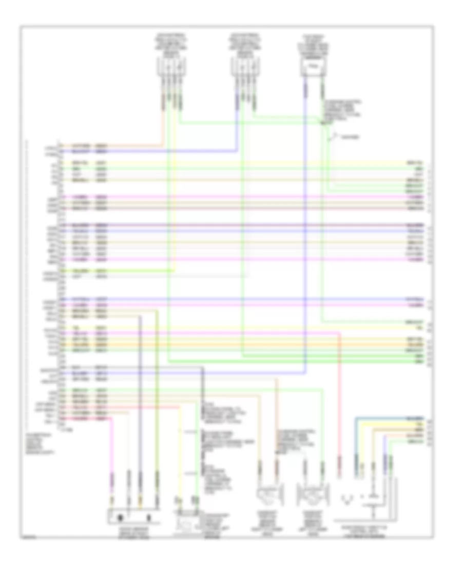
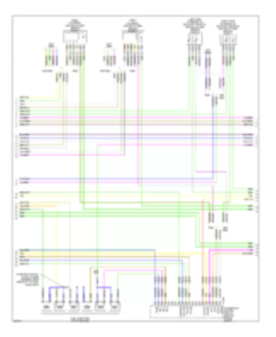
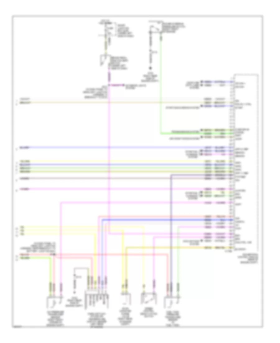
3.5L, Engine Performance Wiring Diagram (1 of 6) for Ford Taurus X Limited 2008
List of elements for 3.5L, Engine Performance Wiring Diagram (1 of 6) for Ford Taurus X Limited 2008:
- (downstream from catalytic converter 1) heated oxygen sensor (ho2s) 12
- (downstream from catalytic converter 2) heated oxygen sensor (ho2s) 22
- (in dash panel to headlight junction harness, near breakout to c140) s184
- (in engine control & fuel charge harness, near breakout to fuel injector 6) s125
- (in engine control & fuel charge harness, near breakout to fuel injector 6) s127
- (top front of right cylinder head) cylinder head temperature sensor
- C175e
- Camshaft position sensor (rear of right cylinder head)
- Camshaft position sensor 2 (rear of left cylinder head)
- Cd1a
- Cd2c
- Cd3e
- Cd4b
- Cd5d
- Cd6f
- Ce206
- Ce208
- Ce210
- Ce233
- Ce234
- Ce303
- Ce304
- Ce305
- Ce306
- Ce307
- Ce308
- Ce321
- Ce412
- Cht
- Cid1
- Cid2
- Ckp sens +
- Ckp sens -
- Crankshaft position sensor (lower left rear of engine)
- De135
- Electronic throttle control (etc) (top rear of engine)
- Ho2s11
- Ho2s12
- Ho2s21
- Ho2s22
- Htr12
- Htr22
- Ia1
- Ia2
- Inj-2
- Inj-4
- Inj-6
- Ip1
- Ip2
- Knock sensor (rear of right cylinder head)
- Ksl1 +
- Ksl1 -
- Ksl2+
- Ksl2-
- Le448
- Le449
- Le450
- Le451
- Le452
- Le453
- Non-pzev
- Pcvhc
- Powertrain control module (rear of engine compt)
- Re135
- Re323
- Re324
- Re429
- Ref1
- Ref2
- S130 (in engine control & fuel charge harness, in breakout to c140)
- Shd rtn
- Sn1
- Sn2
- Tacm+
- Tan
- Ve706
- Ve707
- Ve711
- Ve712
- Ve731
- Ve733
- Ve735
- Ve737
- Ve801
- Ve802
- Ve826
- Ve827
- Vrs rtn
3.5L, Engine Performance Wiring Diagram (2 of 6) for Ford Taurus X Limited 2008
List of elements for 3.5L, Engine Performance Wiring Diagram (2 of 6) for Ford Taurus X Limited 2008:
- (in engine control & fuel charge harness, near breakout to fuel injector 6)
- (left side of engine, on exhaust manifold) heated oxygen sensor (ho2s) 21
- (not used)
- (pzev)
- (pzev) universal heated oxygen sensor (ho2s) 11
- (right side of engine, on exhaust manifold) heated oxygen sensor (ho2s) 11
- C175e
- Ce205
- Ce207
- Ce209
- Ce235
- Ce236
- Ce328
- Ce421
- Ce422
- Ce426
- E-sigrtn
- Etc rtn
- Etcref
- Fuel injectors (top of engine)
- Htr11
- Htr21
- Inj-1
- Inj-3
- Inj-5
- Le134
- Non- pzev
- Non-pzev
- Pcvfhc
- Powertrain control module (rear of engine compt)
- Pzev
- Re134
- Re405
- Red
- S126
- Tacm-
- Tp1 ns
- Tp2 ps
- Universal heated oxygen sensor (ho2s) 21
- Vct1
- Vct2
- Ve818
- Ve819
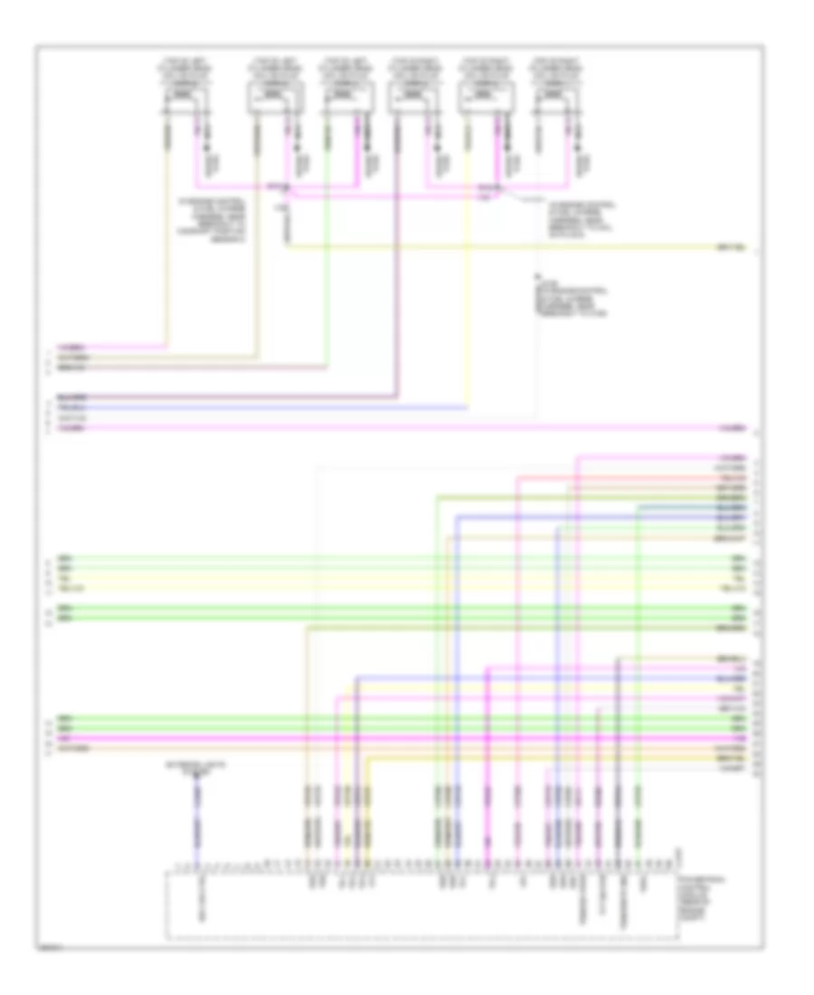
3.5L, Engine Performance Wiring Diagram (3 of 6) for Ford Taurus X Limited 2008
List of elements for 3.5L, Engine Performance Wiring Diagram (3 of 6) for Ford Taurus X Limited 2008:
- (in engine control & fuel charge harness, near breakout to camshaft position sensor 2)
- (in engine control & fuel charge harness, near breakout to coil on plug 5)
- (top of left cylinder head) coil on plug (cop) 4
- (top of left cylinder head) coil on plug (cop) 5
- (top of left cylinder head) coil on plug (cop) 6
- (top of right cylinder head) coil on plug (cop) 1
- (top of right cylinder head) coil on plug (cop) 2
- (top of right cylinder head) coil on plug (cop) 3
- C175t
- Cet05
- Cet06
- Cet07
- Cet08
- Cet09
- Cet10
- Cet19
- Cet25
- Cls28
- Exterior lights system
- Le111
- Lpc
- Nca
- Oss
- Plug spark
- Powertrain control module (rear of engine compt)
- Re406
- Ret24
- Rev lps ctrl
- S124
- S131
- Spark plug
- Ssa
- Ssb
- Ssc
- Ssd
- Sse
- Tcc
- Tft
- Tft sig rtn
- Tr-1
- Tr-2
- Tr-3
- Tr-4
- Tspc
- Tss
- Tss/oss vpwr
- Tss/oss/tr gnd
- Vet26
- Vet27
- Vet29
- Vet30
- Vet31
- Vet33
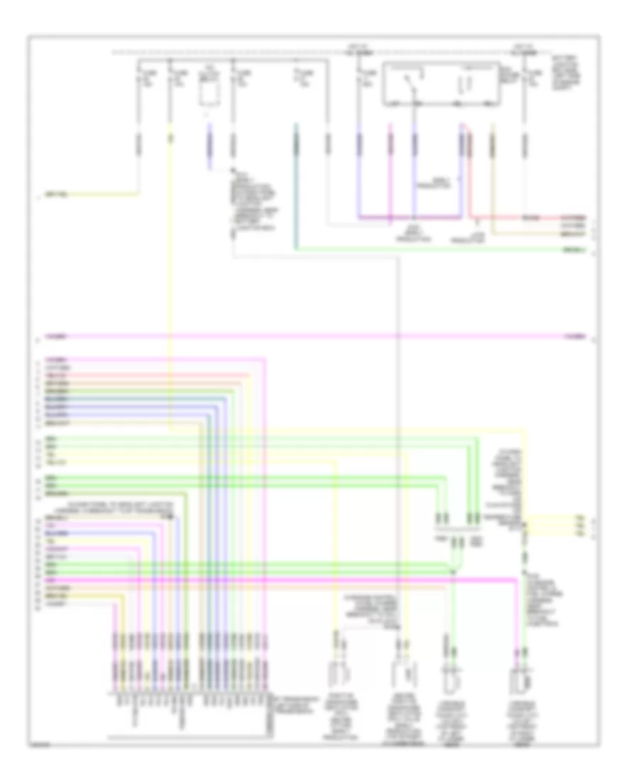
3.5L, Engine Performance Wiring Diagram (4 of 6) for Ford Taurus X Limited 2008
List of elements for 3.5L, Engine Performance Wiring Diagram (4 of 6) for Ford Taurus X Limited 2008:
- (in dash panel to headlight junction harness, in breakout to 6f transmission) s173
- (in dash panel to headlight junction harness, near breakout to mass air flow/intake air temperature sensor) s113
- (in engine control & fuel charge harness, near breakout to coil on plug 5) s123
- 6f transmission (left side of transmission)
- A/c clutch relay
- Battery junction box (bjb) (left side of engine compt)
- Cet05
- Cet06
- Cet07
- Cet08
- Cet09
- Cet10
- Cet19
- Cet25
- Early production
- Fuse 10a
- Fuse 15a
- Fuse 50a
- Heated positive crankcase ventilation (pcv) valve (early production) (top of right cylinder head)
- Hot at all times
- Late production
- Le111
- Lpc
- Non- pzev
- Oss
- Pcm power relay
- Positive crankcase ventilation (pcv) heated fitting (early production)
- Pzev
- Re406
- Ret24
- S128 (in engine control & fuel charge harness, near breakout to fuel injector 6)
- S151 (early production)
- S162
- Ssa
- Ssb
- Ssc
- Ssd
- Sse
- Tcc
- Tft
- Tft sig rtn
- Tr gnd
- Tr-1
- Tr-2
- Tr-3
- Tr-4
- Tspc
- Tss
- Tss/oss gnd
- Tss/oss vpwr
- Variable camshaft timing (vct) valve 1 (top front of right cylinder head)
- Variable camshaft timing (vct) valve 2 (top front of left cylinder head)
- Vet26
- Vet27
- Vet29
- Vet30
- Vet31
- Vet32
- Vet33
3.5L, Engine Performance Wiring Diagram (5 of 6) for Ford Taurus X Limited 2008
List of elements for 3.5L, Engine Performance Wiring Diagram (5 of 6) for Ford Taurus X Limited 2008:
- (in dash panel to headlight junction harness, near breakout to anti-lock brake system module) s117
- (in dash panel to headlight junction harness, near breakout to anti-lock brake system module) s163
- Accelerator pedal position (app) sensor (top of accelerator pedal assembly)
- Appsrtn1
- Appsrtn2
- Battery junction box (bjb) (left side of engine compt)
- C-ref
- C-sigrtn
- C175b
- C3127
- Canvnt
- Case gnd
- Cbb47
- Cdb06
- Ce114
- Ce226
- Ce911
- Computer data lines system
- Cruise control system
- Evap canister vent control solenoid (under right rear of vehicle)
- Feps
- Fpc
- Fuel pump module
- Fuel pump motor diode
- Fuel pump relay
- Fuse 10a
- Fuse 15a
- G102 (right rear side of engine compt)
- G300 (taurus x) g305 (taurus & sable) (at base of right "c" pillar)
- Gd113
- Gd148
- Hot at all times
- Inertia fuel shutoff (ifs)
- Instrument cluster system
- Kapwr
- Le424
- Pnk
- Powertrain control module (rear of engine compt)
- Pwr gnd 1
- Pwr gnd 2
- Pwr gnd 3
- Pwr gnd 4
- Re136
- Re137
- Re407
- Res08
- S118
- S171
- Sbb23
- Sccs
- Sccs rtn
- Switch
- Ves10
- Vpwr1
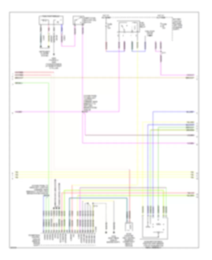
3.5L, Engine Performance Wiring Diagram (6 of 6) for Ford Taurus X Limited 2008
List of elements for 3.5L, Engine Performance Wiring Diagram (6 of 6) for Ford Taurus X Limited 2008:
- (in dash panel to headlight junction harness, near breakout to battery junction box)
- A/c pressure transducer sensor (right front corner of engine compt)
- Accr
- Acpt
- Air conditioning system
- App 1v ref
- App 2v ref
- App1
- App2
- App3
- Boo
- Bps
- Brake pedal position (bpp) switch (under left side of dash)
- C-sig rtn
- C175b
- C2280d
- Cbb39
- Ccb08
- Ccs09
- Cdc10
- Cdc12
- Cdc15
- Cdc35
- Ce132
- Ce237
- Ce336
- Ce608
- Ces09
- Cet34
- Ch302
- Computer data lines system
- Cooling fans system
- Evap canister purge valve (right rear of engine compt)
- Evapcpv
- Exterior lights system
- Fan ctrl var
- Fpm
- Ftpt
- Ftptref
- Fuel tank pressure transducer sensor (in fuel tank)
- Fuse 15a
- G102 (right rear side of engine compt)
- Gencom
- Genmon
- Hot at all times
- Hs can +
- Hs can -
- Iat
- Ign
- Injpwrm
- Le136
- Le137
- Le230
- Maf
- Mafrtn
- Mass air flow/ intake air temperature (maf/iat) sensor (left rear of engine)
- Over drive cancel
- Pcm rly ctrl
- Power steering pressure switch (right front of engine)
- Powertrain control module (rear of engine compt)
- Pspt
- Pwr gnd
- Re320
- S118
- S119
- S213 (in dash panel to headlight junction harness, in breakout to c210)
- Smart junction box (sjb) (under left side of dash)
- Smc
- Smrc
- Speed control deactivation switch
- Start
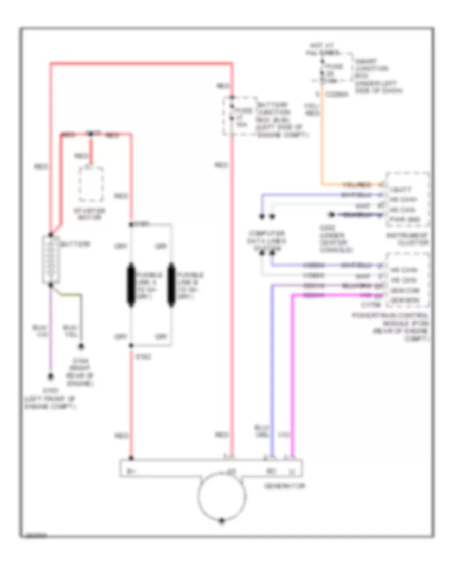
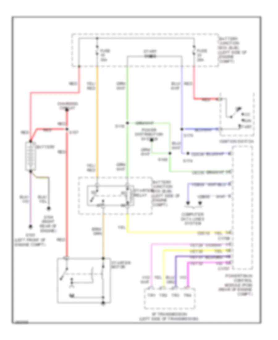
- Starting/ charging system
- Starting/charging system
- Transmissions system
- Vdb04
- Vdb05
- Ve701
- Ve702
- Ve703
- Ve740
- Ve807
- Ve922
- Vec03
- Vh433
- Vpwr
EXTERIOR LIGHTS
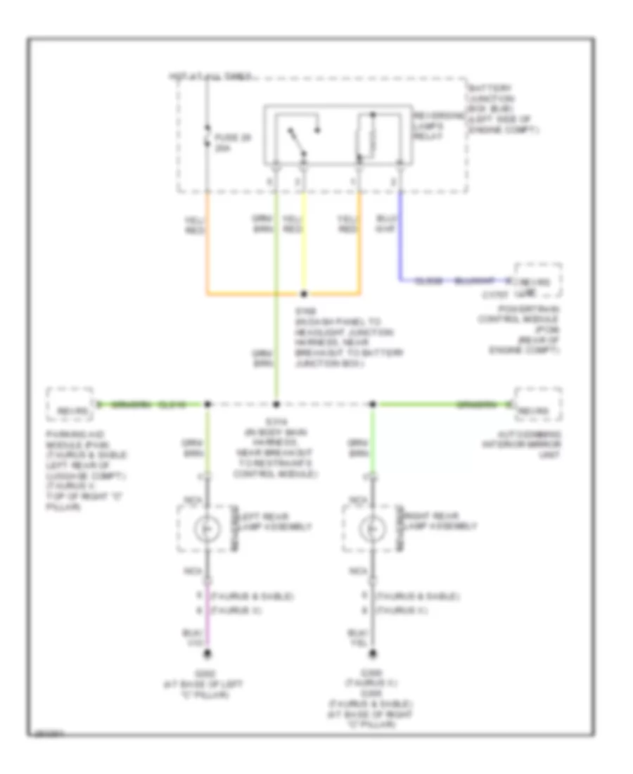
Back-up Lamps Wiring Diagram for Ford Taurus X Limited 2008
List of elements for Back-up Lamps Wiring Diagram for Ford Taurus X Limited 2008:
- (taurus & sable)
- (taurus x)
- Auto-dimming interior mirror unit
- Battery junction box (bjb) (left side of engine compt)
- Cls10
- Cls28
- Fuse 26 20a
- G300 (taurus x) g305 (taurus & sable) (at base of right "c" pillar)
- G302 (at base of left "c" pillar)
- Hot at all times
- Left rear lamp assembly reverse
- Nca
- Parking aid module (pam) (taurus & sable: left rear of luggage compt) (taurus x: top of right "c" pillar)
- Powertrain control module (pcm) (rear of engine compt)
- Reversing lamps relay
- Revrs
- Revrs lmp c175t
- Right rear lamp assembly reverse
- S168 (in dash panel to headlight junction harness, near breakout to battery junction box)
- S314 (in body main harness, near breakout to restraints control module)
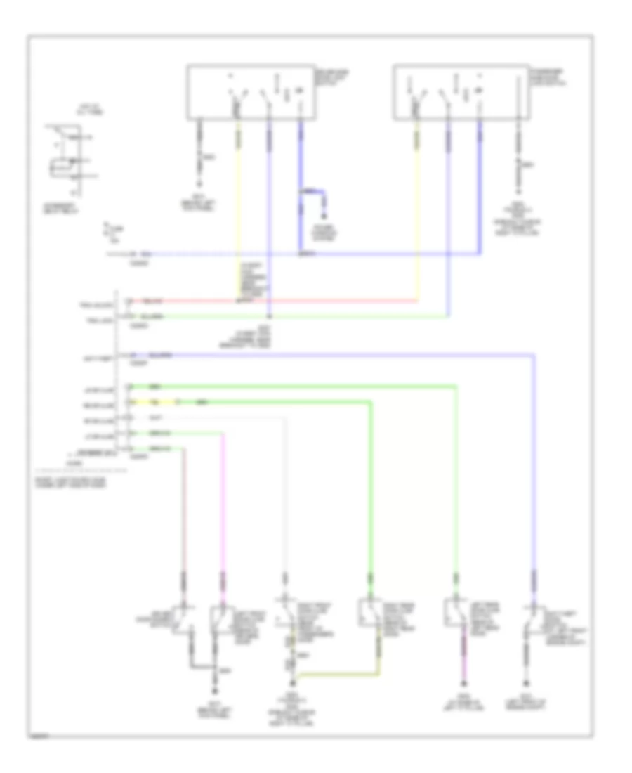
Exterior Lamps Wiring Diagram for Ford Taurus X Limited 2008
List of elements for Exterior Lamps Wiring Diagram for Ford Taurus X Limited 2008:
- (in body main harness, near breakout to restraints control module) s313
- Auto
- Backup lamps circuit
- Boo
- Brake pedal position (bpp) switch (under left side of dash)
- C175b
- C2280b
- C2280d
- C2280e
- C2280f
- Ccb08
- Center stack switch assembly
- Computer data lines system
- Flash to pass
- Fuse 2 15a
- Fuse 20a
- Fuse 22 15a
- G100 (right front of engine compt)
- G101 (left front of engine compt)
- G202 (under center console)
- G300 (at base of right "c" pillar)
- G302 (at base of left "c" pillar)
- Hazard
- Headlamp switch
- Hi beam
- High beam
- High mounted stoplamp
- Hot at all times
- Hs can +
- Hs can -
- Left
- Left front park/turn lamp
- Left front side lamp
- Left rear lamp assembly
- Left turn
- Lf turn lamp (fet)
- License lamps/ liftgate release switch
- Low
- Low beam
- Lr stop/ turn lamp (fet)
- Micro
- Ms can +
- Ms can -
- Multi-function switch
- Nca
- Off
- Off ftp
- Park
- Park lamp relay
- Powertrain control module (pcm) (rear of engine compt)
- Reverse
- Rf turn lamp (fet)
- Right
- Right front park/turn lamp
- Right front side lamp
- Right rear lamp assembly
- Right turn
- Rr stop/ turn lamp (fet)
- S111 (in dash panel to headlight junction harness, in breakout to right front impact sensor)
- S213 (in dash panel to headlight junction harness, in breakout to c210)
- S223
- S400
- Smart junction box (sjb) (under left side of dash)
- Stop/turn
- Turn
- Vdb04
- Vdb05
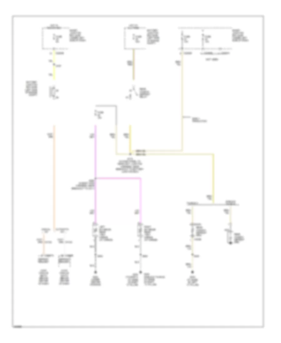
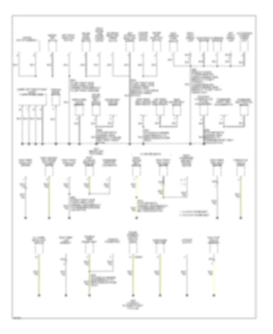
GROUND DISTRIBUTION
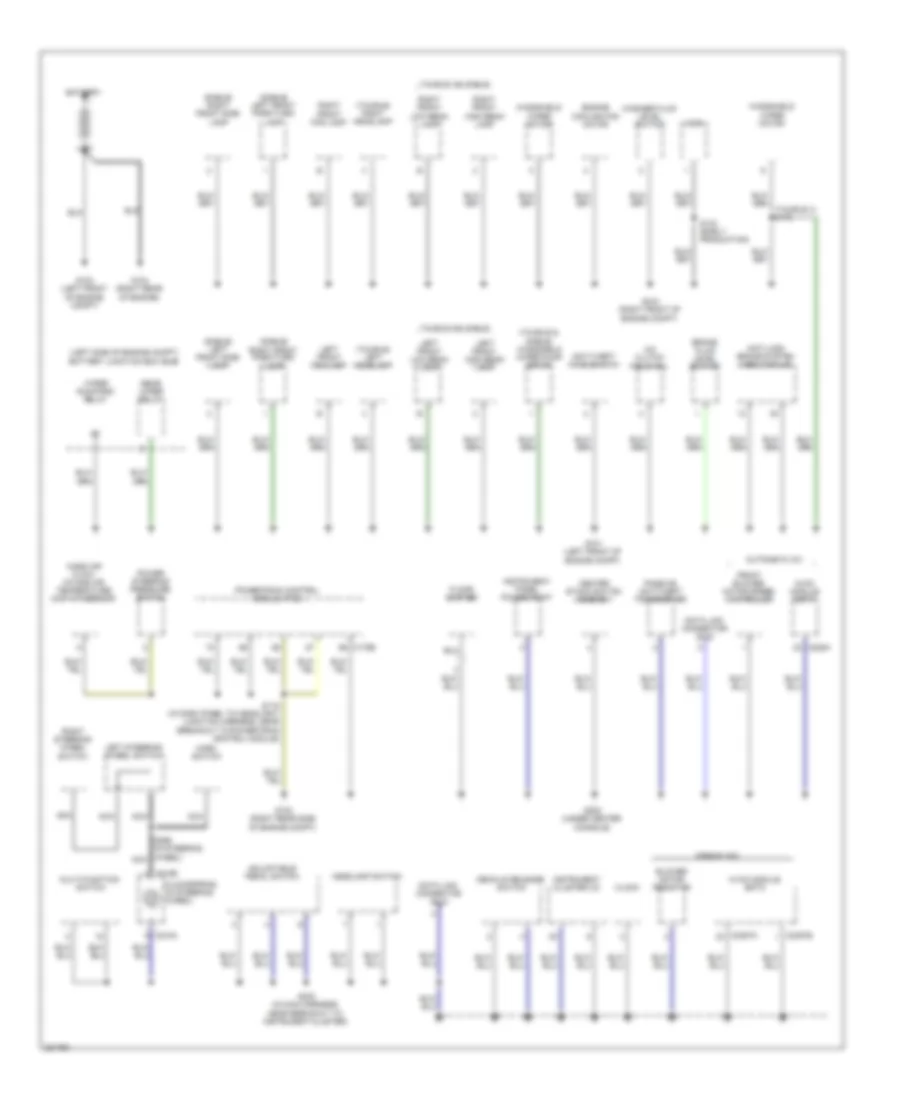
Ground Distribution Wiring Diagram (1 of 4) for Ford Taurus X Limited 2008
List of elements for Ground Distribution Wiring Diagram (1 of 4) for Ford Taurus X Limited 2008:
- (left side of engine compt) battery junction box (bjb)
- (sable) left front park/turn lamp
- (sable) left front side lamp
- (sable) right front park/turn lamp
- (sable) right front side lamp
- (taurus & sable) windshield wiper pump motor
- (taurus x) s175
- (taurus) left headlamp
- (taurus) right headlamp
- A/c clutch field coil
- Adjustable pedal switch
- Anti-lock brake system (abs) module
- Anti-theft hood switch
- Automatic a/c
- Battery
- Blower motor resistor
- Brake fluid level switch
- C175b
- C218a
- C218b
- C228a
- C2357a
- C2357b
- Center stack switch assembly
- Clock
- Clockspring (in steering wheel)
- Data link connector (dlc)
- Decklid release switch
- Engine cooling fan motor
- Floor shifter
- Front blower motor speed controller
- G100 (right front of engine compt)
- G101 (left front of engine compt)
- G102 (right rear side of engine compt)
- G103 (left front of engine compt)
- G104 (right rear of engine)
- G202 (under center console)
- Headlamp switch
- Horn
- Horn switch
- Hvac module datc
- Hvac module emtc
- Instrument cluster (ic)
- Instrument panel power point
- Left front fog lamp
- Left front high beam lamp
- Left front low beam lamp
- Left steering wheel switch
- Manual a/c
- Mass air flow/ intake air temperature (maf/iat) sensor
- Multi-function switch
- Nca
- Passive anti-theft transceiver
- Power steering pressure switch
- Powertrain control module (pcm)
- Rear wiper relay
- Right front fog lamp
- Right front high beam lamp
- Right front low beam lamp
- Right steering wheel switch
- S118 (in dash panel to headlight junction harness, near breakout to powertrain control module)
- S133 (early production)
- S223 (in main harness, near breakout to instrument cluster)
- S299 (in steering wheel) nca
- Taurus x & sable
- Washer fluid level switch
- Windshield wiper motor
- Wiper run/park relay
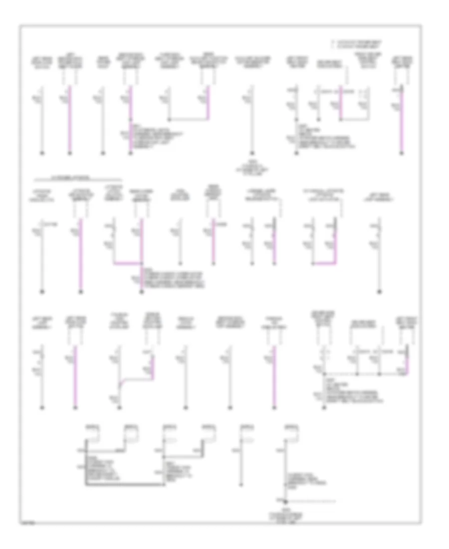
Ground Distribution Wiring Diagram (2 of 4) for Ford Taurus X Limited 2008
List of elements for Ground Distribution Wiring Diagram (2 of 4) for Ford Taurus X Limited 2008:
- (under left side of dash) smart junction box (sjb)
- All wheel drive (awd) module
- Auto-dimming interior mirror unit
- C2368a
- Console power point
- Console rear power point
- Driver door disarm switch
- Driver safety belt buckle switch
- Driver seat position sensor
- Driver side door lock switch
- Electronic compass
- Exterior rear view mirror switch
- Front driver side power window motor
- Front heated seat module
- Front passenger side seat control switch
- Fuel pump module assembly
- G210 (behind left kick panel)
- G300 (taurus x) (at base of right "c" pillar)
- Keypad switch assembly
- Left exterior rear view mirror
- Left front door ajar switch
- Left rear seat heated seat switch
- Left vanity mirror lamp
- Liftgate switch
- Master window adjust switch
- Memory set switch
- Nca
- Occupant classification system module (ocsm)
- Overhead console
- Parking aid module (pam)
- Parking brake switch
- Passenger safety belt buckle switch
- Passenger seat position sensor
- Passenger side door lock switch
- Power steering control module (pscm)
- Rear heated seat module
- Rear wiper motor assembly
- Right exterior rear view mirror
- Right front door ajar switch
- Right front seat back heater
- Right rear door ajar switch
- Right rear lamp assembly
- Right rear seat back heater
- Right rear seat heated seat switch
- Right second row power fold seat motor
- Right vanity mirror lamp
- Roof opening panel module
- S500 (in left front door window regulator harness, near breakout to left front speaker)
- S502 (in left front door window regulator harness, near breakout to exterior rearview mirror switch)
- S902 (sable & taurus: in inside rearview mirror harness, near breakout to c907) (taurus x : in inside rearview mirror harness, near breakout to left vanity mirror light)
- Subwoofer amplifier
- W/ 2-way power seat
- W/ heated seats
- W/o 2-way power seat
Ground Distribution Wiring Diagram (3 of 4) for Ford Taurus X Limited 2008
List of elements for Ground Distribution Wiring Diagram (3 of 4) for Ford Taurus X Limited 2008:
- (in body main harness, near breakout to c9028) s385
- (sable) led high mounted stoplamp
- (taurus) high mounted stoplamp
- (w/ manual liftgate) liftgate lock actuator
- Auxiliary blower motor resistor assembly
- Breakout to c936)
- Breakout to driver safety canopy module)
- C341a
- C341b
- C402b
- C4174b
- Decklid latch assembly
- Driver seat module (dsm)
- Driver side front seat control switch
- Front driver side seat control switch
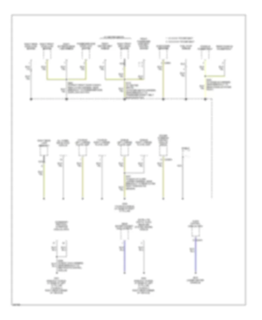
- G302 (taurus & sable) (at base of left "c" pillar)
- G302 (taurus x) (at base of left "c" pillar)
- High mounted stoplamp
- Left front seat back heater
- Left rear door ajar switch
- Left rear lamp assembly
- Left rear seat back heater
- Left second row power fold seat motor
- License lamps/ liftgate release switch
- Liftgate drive motor assembly
- Liftgate latch/ unlatch assembly
- Liftgate/ trunk module (ltm)
- Nca
- Parking aid module (pam)
- Rear auxiliary function selector switch assembly
- Rear power point
- Rear window defrost grid
- Rear wiper motor assembly
- S357 (w/ heated seats) (in power seats harness, near breakout to driver safety belt buckle switch)
- S386 (in body main harness, in nca
- S387 (in body main harness, in nca
- S400 (in rear window wiper motor in rear window wiper motor feed harness, near breakout to rear window defrost grid)
- S911 (in interior lights harness, near breakout to second row seat interior map light assembly)
- Second row seat interior/ map assembly
- Second row seat interior/ map lamp assembly
- Shield
- Third row seat interior/ map lamp assembly
- W/ 6-way power seat
- W/ power liftgate
- W/o 6-way power seat
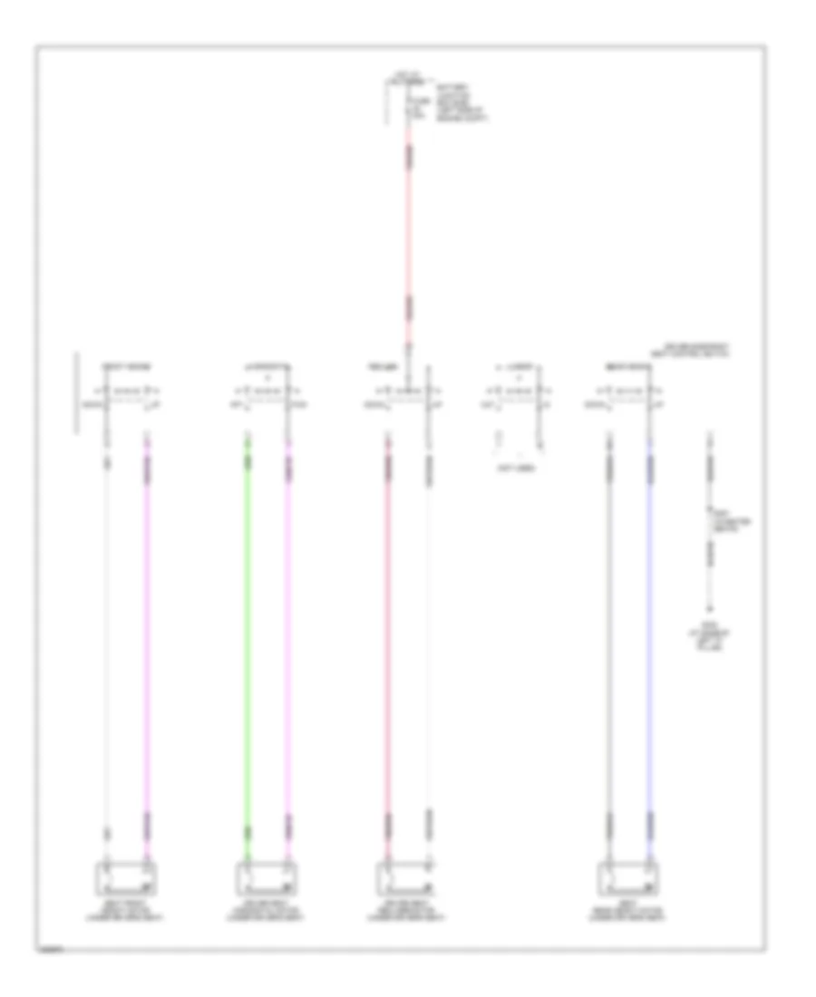
Ground Distribution Wiring Diagram (4 of 4) for Ford Taurus X Limited 2008
List of elements for Ground Distribution Wiring Diagram (4 of 4) for Ford Taurus X Limited 2008:
- (in power seats harness, near breakout to passenger safety belt buckle switch)
- (sable) left license plate lamp
- (sable) right license plate lamp
- (taurus) left license plate lamp
- (taurus) right license plate lamp
- Accessory protocol interface module (apim)
- All wheel drive (awd) module
- Audio control module (acm)
- C2368a
- C240a
- C466a
- Console power point
- Front heated seat module
- Front passenger side seat control switch
- Fuel pump module
- G200 (under center console)
- G305 (taurus & sable) (at base of right "c" pillar)
- G400 (sable & taurus: at base of left "c" pillar) (taurus x: right rear corner of vehicle)
- G401 (sable & taurus: at base of left "c" pillar) (taurus x: right rear corner of vehicle)
- Nca
- Passenger side door lock switch
- Power steering control module (pscm)
- Rear console power point
- Rear entertainment module (retm)
- Right exterior rear view mirror
- Right front door ajar switch
- Right front seat back heater
- Right rear door ajar switch
- Right rear lamp assembly
- S383 (in console harness, near breakout to rear console power point)
- S600 (in right front door window regulator harness, near breakout to passenger side door lock switch)
- Satellite digital audio receiver system (sdars) module
- Sensor)
- Shield
- Subwoofer amplifier
- W/ 2-way power seat
- W/ heated seats
- W/o 2-way power seat
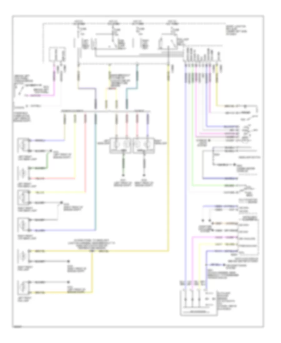
HEADLIGHTS
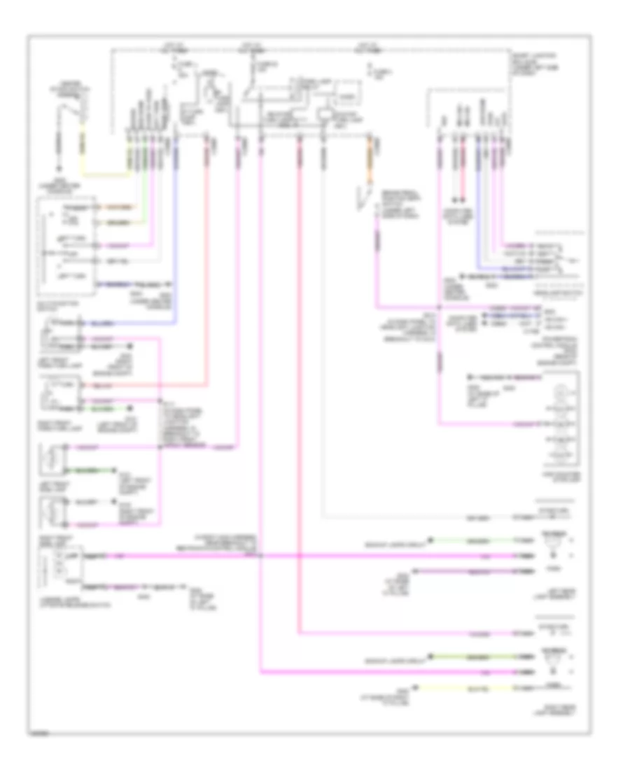
Headlights Wiring Diagram for Ford Taurus X Limited 2008
List of elements for Headlights Wiring Diagram for Ford Taurus X Limited 2008:
- (behind left kick panel) parking brake switch
- (in dash panel to headlight junction harness, near breakout to mass air flow/intake air temperature sensor) s134
- (near breakout to mass air flow/intake air temperature sensor) s110
- Air conditioning system
- Auto
- Auto sens
- Autolamp/ sunload sensor (w/ automatic a/c) (in dash, above glove box)
- C2280a
- C2280b
- C2280c
- C2280e
- C2280f
- Computer data lines system
- Datc hvac module (behind center of dash)
- Drv sunload
- Flash to
- Fog
- Fog ind
- Fog lamp
- Fog lamp lamp relay
- Ftp
- Fuse 10a
- Fuse 15a
- G100 (right front of engine compt)
- G101 (left front of engine compt)
- G202 (under center console)
- G210 (behind left kick panel)
- Headlamp switch
- High
- High beam
- High beam lamp relay
- Hot at all times
- Hs can+ hs can-
- Instrument cluster (ic)
- Interior lights system
- Left front fog lamp
- Left front high beam lamp
- Left front low beam lamp
- Left headlamp
- Left low beam (fet)
- Low
- Low beam
- Ms can+
- Ms can-
- Multi-function switch
- Off
- Park
- Park brk
- Pass sunload
- Rh111
- Right front fog lamp
- Right front high beam lamp
- Right front low beam lamp
- Right headlamp
- Right low beam (fet)
- Rtn c228a
- S201 (in main harness, near breakout to passenger air bag module)
- S223
- Smart junction box (sjb) (under left side of dash)
- Solid state
- Taurus
- Taurus x & sable
- Vdb04
- Vdb05
- Vdb06
- Vdb07
- Vh416
- Vh417
- Windshield wiper motor (left rear of engine compt)
- Wip sts
HORN
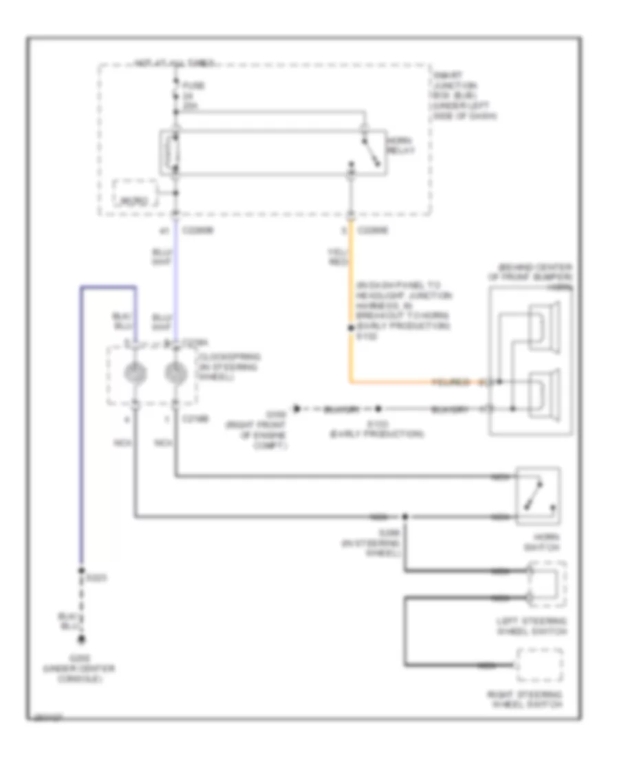
Horn Wiring Diagram for Ford Taurus X Limited 2008
List of elements for Horn Wiring Diagram for Ford Taurus X Limited 2008:
- (behind center of front bumper) horn
- (in dash panel to headlight junction harness, in breakout to horn) (early production) s132
- C218a
- C218b
- C2280b
- C2280e
- Clockspring (in steering wheel)
- Fuse 20a
- G100 (right front of engine compt)
- G202 (under center console)
- Horn relay
- Horn switch
- Hot at all times
- Left steering wheel switch
- Micro
- Nca
- Right steering wheel switch
- S133 (early production)
- S223
- S299 (in steering wheel)
- Smart junction box (bjb) (under left side of dash)
INSTRUMENT CLUSTER
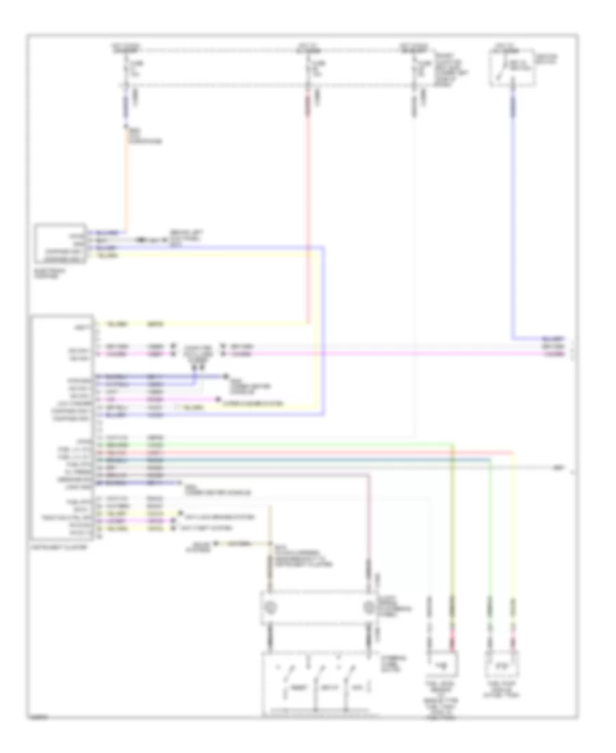
Instrument Cluster Wiring Diagram (1 of 2) for Ford Taurus X Limited 2008
List of elements for Instrument Cluster Wiring Diagram (1 of 2) for Ford Taurus X Limited 2008:
- (behind left kick panel) g210
- Anti-lock brakes system
- Anti-theft system
- C218a
- C218b
- C2280a
- C2280b
- Cbp29
- Cca15
- Clock- spring (in steering wheel)
- Cmc20
- Cmc24
- Cmc29
- Compass mod +
- Compass mod -
- Computer data lines system
- Electronic compass
- Fuel level sensor (w/ saddle type fuel tank) (awd: in fuel tank)
- Fuel lvl in 1
- Fuel lvl in 2
- Fuel pump module (in fuel tank)
- Fuel rtn
- Fuse 10a
- Fuse 5a
- G202 (under center console)
- Gd111
- Gnd
- Hot at all times
- Hot in run or start
- Hs can +
- Hs can -
- Ignition switch
- Info
- Instrument cluster
- Key in ignition
- Logic gnd
- Low washer
- Message sig
- Ms can +
- Ms can -
- Nca
- Oil press
- Pats rx
- Pats tx
- Pnk
- Pwr gnd
- Reset
- Rmc27
- Rmc32
- Rmc33
- S218 (in main harness, near breakout to instrument cluster)
- S902
- S903 (w/o microphone)
- Sbp26
- Setup
- Smart junction box (sjb) (under left side of dash)
- Sound systems
- Steering wheel switch
- Swc1 -
- Traction ctrl off
- Vbatt
- Vdb04
- Vdb05
- Vdb06
- Vdb07
- Vmc11
- Vmc23
- Vmc30
- Vmc31
- Vpwr
- Vrt23
- Vrt24
- Wiper/washer system
Instrument Cluster Wiring Diagram (2 of 2) for Ford Taurus X Limited 2008
List of elements for Instrument Cluster Wiring Diagram (2 of 2) for Ford Taurus X Limited 2008:
- (at base of right "c" pillar) (taurus x) g300
- (not used)
- (under center console) g202
- Brake fluid level switch (left rear of engine compt)
- Brk fluid sw rtn
- C2280b
- C2280c
- C2280f
- C228ob
- C4174a
- C983
- Clock
- Cpl58
- Fuse 10a
- G101 (left front of engine compt)
- G210 (behind left kick panel)
- G302 (at base of left "c" pillar)
- G305 (sable & taurus) (at base of right "c" pillar)
- Gnd
- Hot at all times
- Illum
- Interior lights system
- Key in ign
- Left front door ajar switch (rear of driver's door)
- Left rear door ajar switch (rear of left rear door)
- Lf dr ajar
- Liftgate/ glass ajar
- Liftgate/glass ajar
- Liftgate/trunk module (ltm) (base of left "d" pillar)
- Lr dr ajar
- Micro
- Ms can +
- Ms can -
- Oil pressure switch (left front of engine block)
- Park brk
- Parking brake switch (behind left kick panel)
- Rf dr ajar
- Right front door ajar switch (rear of front passenger's door)
- Right rear door ajar switch (rear of right rear door)
- Rr dr ajar
- S366 (in body main harness, near breakout to left rear light assembly)
- S510
- S600
- Smart junction box (sjb) (under left side of dash)
- Sw rtn brk fluid
INTERIOR LIGHTS
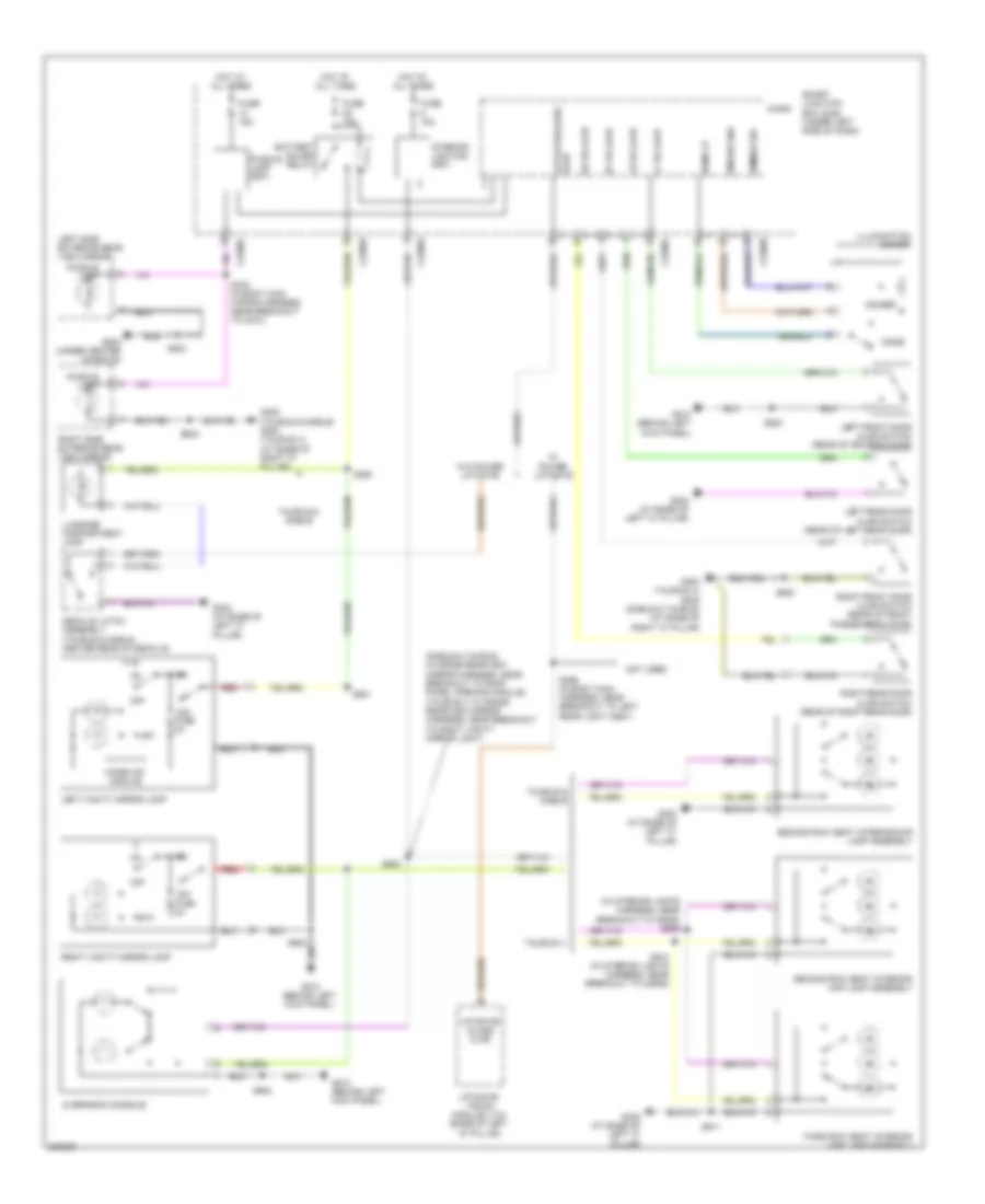
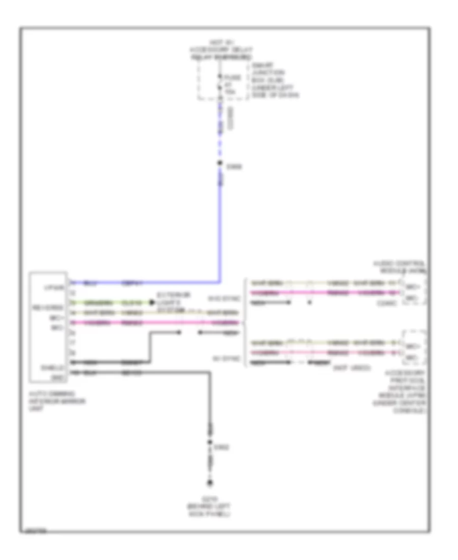
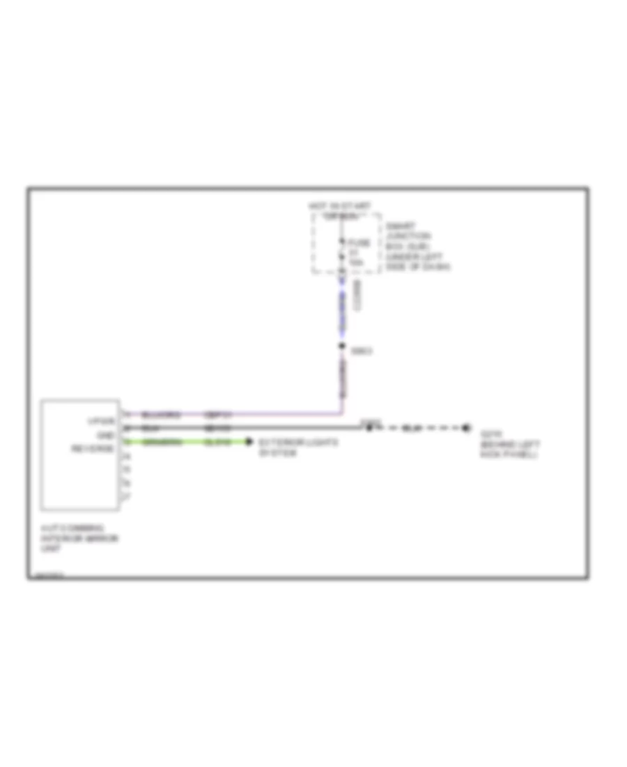
Courtesy Lamps Wiring Diagram for Ford Taurus X Limited 2008
List of elements for Courtesy Lamps Wiring Diagram for Ford Taurus X Limited 2008:
- (in interior lights harness, near breakout to c9092) s909
- (sable & taurus: in inside rearview mirror harness, near breakout to roof panel opening module) (taurus x: in inside rearview mirror harness, near breakout to right vanity mirror light)
- Battery saver relay
- C2280a
- C2280b
- C2280c
- C2280d
- Decklid latch assembly (taurus & sable: center rear of decklid)
- Dim sw gnd
- Dimmer
- Dimmer sw
- Dome
- Dome lp
- Fuse 10a
- Fuse 15a
- G202 (under center console)
- G210 (behind left kick panel)
- G300 (taurus x) g305 (sable & taurus) (at base of right "c" pillar)
- G302 (at base of left "c" pillar)
- G305 (taurus & sable) g300 (taurus x) (at base of right "c" pillar)
- Homelink module
- Hot at all times
- Illumination dimmer
- Interior lighting (fet)
- Left front door ajar switch (rear of driver's door)
- Left rear door ajar switch (rear of left rear door)
- Left side exterior rear view mirror
- Left vanity mirror lamp
- Lf dr ajar
- Liftgate/ glass ajar
- Liftgate/ trunk module (ltm) (base of left "d" pillar)
- Liftgate/glass ajar
- Lr dr ajar
- Luggage compartment lamp
- Micro
- Not used
- Off
- Off fuse 2a
- Overhead console
- Puddle lamp
- Puddle lamp (fet)
- Red
- Rf dr ajar
- Right front door ajar switch (rear of front passenger's door)
- Right rear door ajar switch (rear of right rear door)
- Right side exterior rear view mirror
- Right vanity mirror lamp
- Rr dr ajar
- S332 (in body main wiring harness, near breakout to c510)
- S360
- S366 (in body main harness, near breakout to left rear light assy)
- S500
- S502
- S600
- S900
- S901
- S902
- S910 (in interior lights harness, near breakout to c9092)
- S911
- Second row seat interior/ map lamp assembly
- Second row seat interior/map lamp assembly
- Smart junction box (sjb) (under left side of dash)
- Taurus & sable
- Taurus x
- Third row seat interior/ map lamp assembly
- W/ power liftgate
- W/o power liftgate
Instrument Illumination Wiring Diagram for Ford Taurus X Limited 2008
List of elements for Instrument Illumination Wiring Diagram for Ford Taurus X Limited 2008:
- (in body main harness, near breakout to c312) s365
- (not used)
- Adjustable pedal switch
- Back- lighting led (fet)
- C218a
- C218b
- C2280b
- Center stack switch assembly
- Clock
- Clockspring (in steering wheel)
- Decklid release switch
- Dim sw gnd
- Dimmer
- Dimmer sw
- Dome
- Dome lp
- Floor shifter
- Fuse 15a
- G202 (under center console)
- G210 (behind left kick panel)
- G302 (at base of left "c" pillar)
- Gnd
- Headlamp switch
- Hot at all times
- Illum
- Illumination dimmer
- Left rear seat heated seat switch
- Left steering wheel switch
- Micro
- Nca
- Rear auxiliary function selector switch assembly
- Right rear seat heated seat switch
- Right steering wheel switch
- S206 (in main harness, near breakout to autolamp/ sunload sensor)
- S223
- S298 (in steering wheel)
- S299
- S380 (in console harness, near breakout to rear console power point)
- S381
- S911
- Smart junction box (sjb) (under left side of dash)
- White led (fet)
MEMORY SYSTEMS
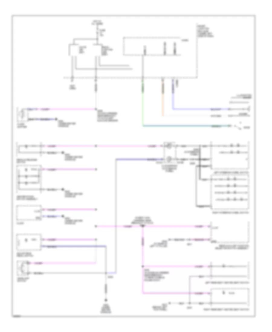
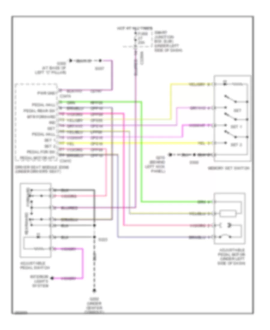
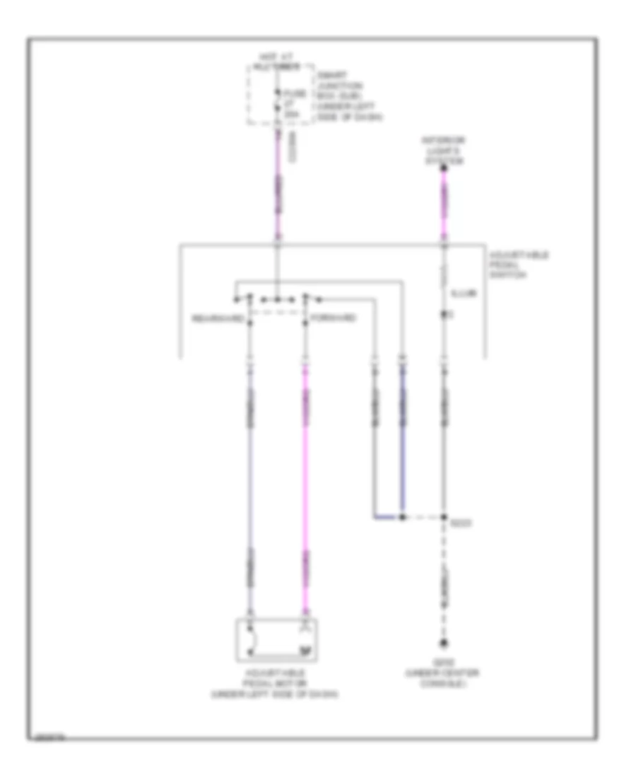
Adjustable Pedal Wiring Diagram for Ford Taurus X Limited 2008
List of elements for Adjustable Pedal Wiring Diagram for Ford Taurus X Limited 2008:
- Adjustable pedal motor (under left side of dash)
- Adjustable pedal switch
- C2280a
- C341a
- C341c
- Cd147
- Cpp09
- Cpp10
- Cps14
- Cps15
- Cps16
- Cps55
- Driver seat module (dsm) (under driver's seat)
- Forward
- Fuse 20a
- G202 (under center console)
- G210 (behind left kick panel)
- G302 (at base of left "c" pillar)
- Hot at all times
- Ind
- Interior lights system
- Lpp06
- Memory set switch
- Mtr forward
- Pedal for sw
- Pedal hall
- Pedal motor aft
- Pedal rear sw
- Pwr gnd
- Rearward
- Rpp06
- S223
- S357
- S500
- Set
- Set 1
- Set 2
- Smart junction box (sjb) (under left side of dash)
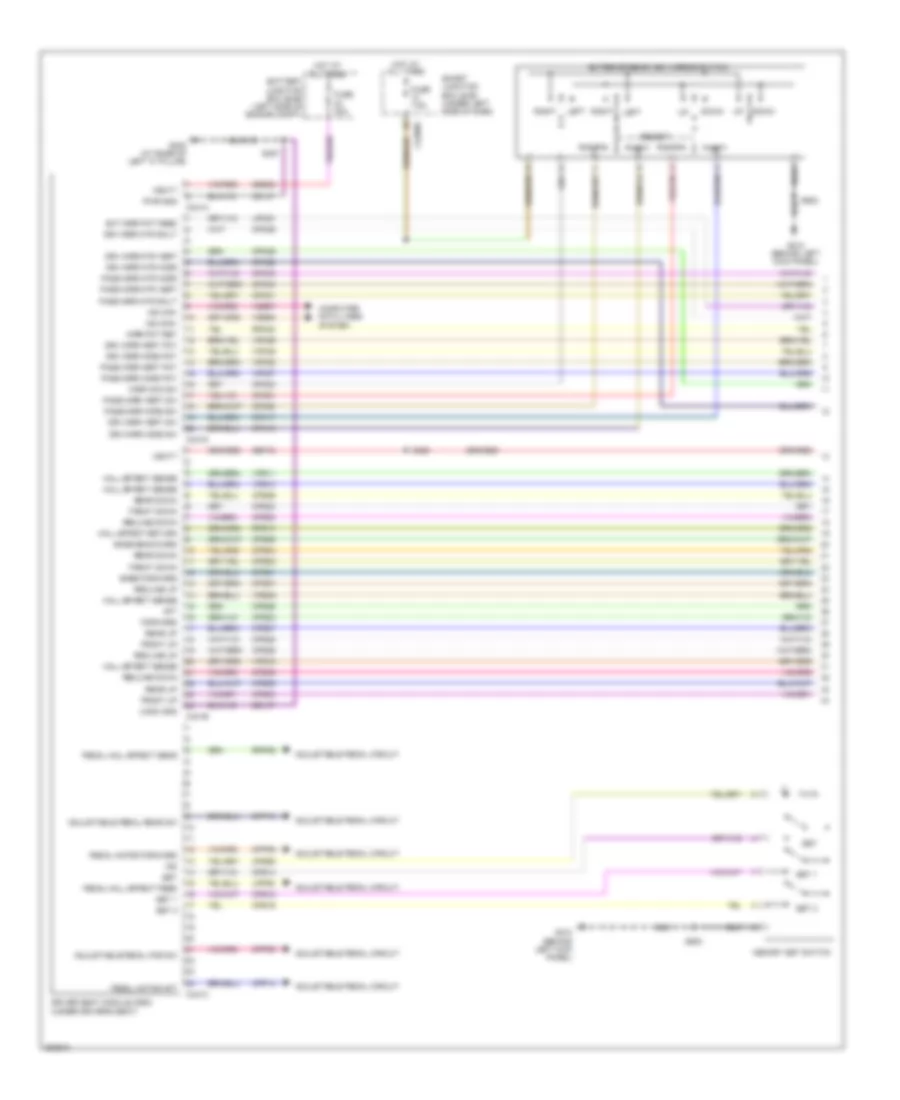
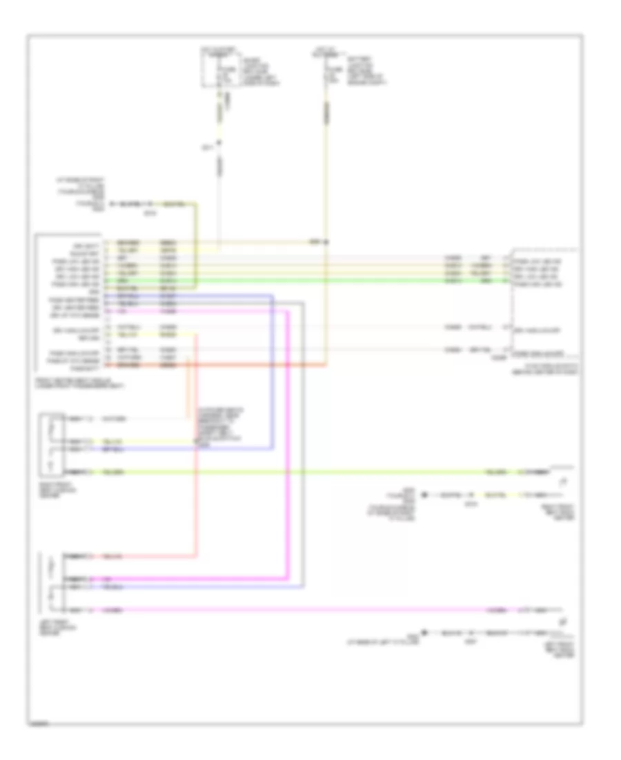
Memory Seat & Mirrors Wiring Diagram (1 of 2) for Ford Taurus X Limited 2008
List of elements for Memory Seat & Mirrors Wiring Diagram (1 of 2) for Ford Taurus X Limited 2008:
- Adjustable pedal circuit
- Adjustable pedal for sw
- Adjustable pedal rear sw
- Aft
- Base backward
- Base forward
- Battery junction box (bjb) (left side of engine compt)
- C2280d
- C341a
- C341b
- C341c
- C341d
- Cd147
- Computer data lines system
- Cpm16
- Cpm17
- Cpm20
- Cpm21
- Cpm23
- Cpm26
- Cpm28
- Cpm29
- Cpm31
- Cpm33
- Cpm34
- Cpp09
- Cpp10
- Cps01
- Cps02
- Cps03
- Cps04
- Cps05
- Cps06
- Cps07
- Cps14
- Cps15
- Cps16
- Cps23
- Cps24
- Cps25
- Cps26
- Cps27
- Cps29
- Cps30
- Cps55
- Down
- Driver seat module (dsm) (under driver's seat)
- Drv mirr horz pot
- Drv mirr horz sw
- Drv mirr mtr dn/lt
- Drv mirr mtr horz
- Drv mirr mtr vert
- Drv mirr vert pot
- Drv mirr vert sw
- Ext mirr pot feed
- Exterior rear view mirror switch
- Forward
- Front down
- Front up
- Fuse 30a
- Fuse 7.5a
- G210 (behind left kick panel)
- G302 (at base of left "c" pillar)
- Gd147
- Hall effect return
- Hall effect sense
- Hot at all times
- Ind
- Left
- Logic gnd
- Lpm30
- Lpp06
- Memory set switch
- Mirr com sw
- Mirr pot ret
- Ms can+
- Ms can-
- Pass mirr horz pot
- Pass mirr horz sw
- Pass mirr mtr dn/lt
- Pass mirr mtr horz
- Pass mirr mtr vert
- Pass mirr vert pot
- Pass mirr vert sw
- Pedal hall effect feed
- Pedal hall effect sens
- Pedal motor aft
- Pedal motor forward
- Pwr gnd
- Rear down
- Rear up
- Recline down
- Recline up
- Right
- Rpm30
- Rpp06
- Rps13
- S326
- S357
- S500
- S502
- Sbb32
- Sbp12
- Select
- Set
- Set 1
- Set 2
- Smart junction box (sjb) (under left side of dash)
- Vbatt
- Vdb06
- Vdb07
- Vpm35
- Vpm36
- Vpm37
- Vpm38
- Vps09
- Vps10
- Vps11
- Vps12
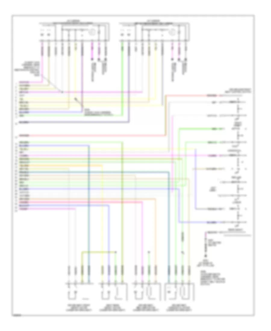
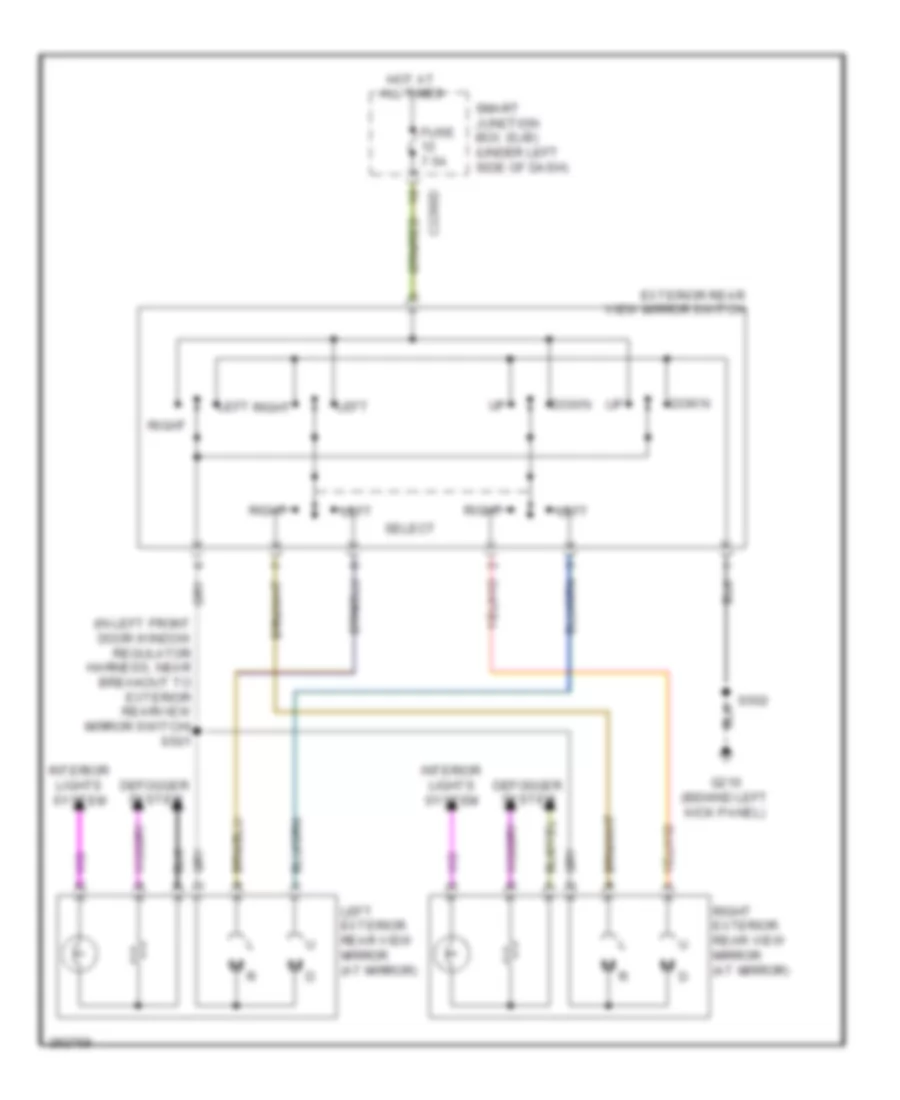
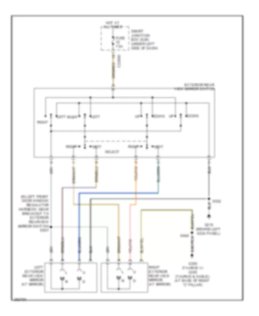
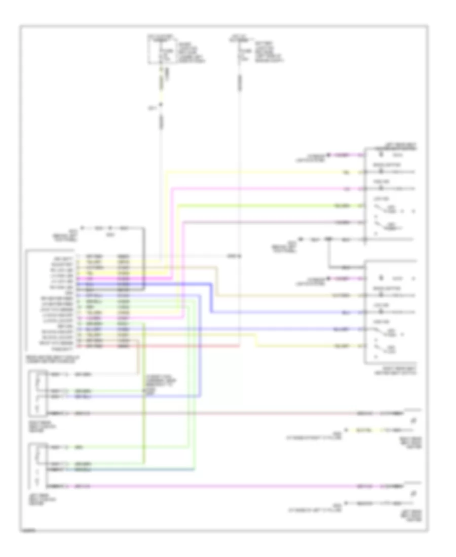
Memory Seat & Mirrors Wiring Diagram (2 of 2) for Ford Taurus X Limited 2008
List of elements for Memory Seat & Mirrors Wiring Diagram (2 of 2) for Ford Taurus X Limited 2008:
- (at mirror) left exterior rear view mirror
- (at mirror) right exterior rear view mirror
- (in body main harness, near breakout to restraints control module) s328
- (not used)
- Aft
- Defogger system
- Down
- Driver seat front height motor (under driver's seat)
- Driver seat horizontal motor (under driver's seat)
- Driver seat recliner motor (under driver's seat)
- Driver side front seat control switch
- Front height
- Fwd
- G302 (at base of left "c" pillar)
- Horizontal
- Interior lights system
- Lumbar
- Out
- Rear height
- Recline
- S329 (in body main harness, near breakout to c311)
- S356 (in power seats harness, near breakout to driver safety belt buckle switch)
- S357 (w/ heated seats)
- Seat rear height motor (under driver's seat)
NAVIGATION
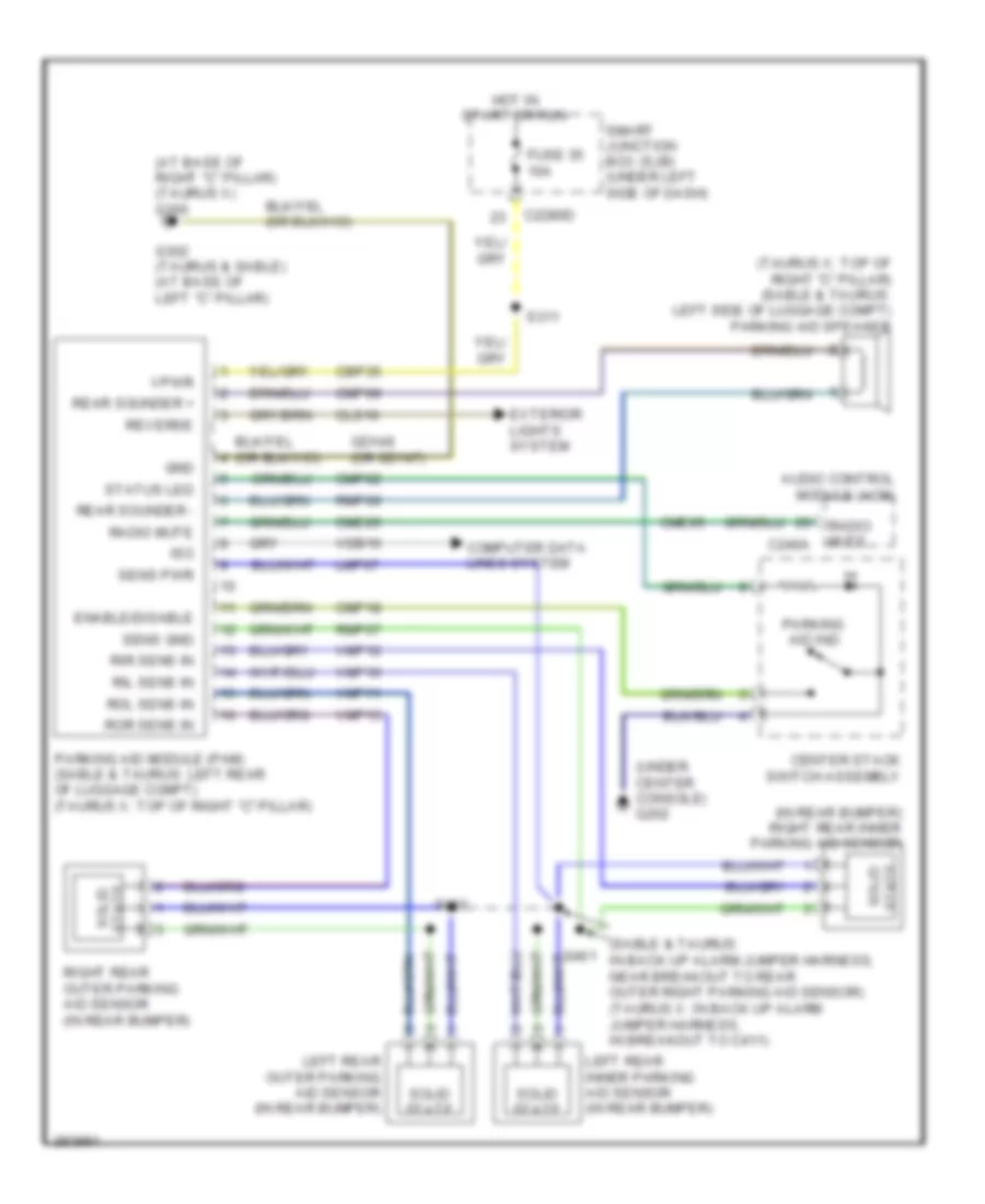
Parking Assistant Wiring Diagram for Ford Taurus X Limited 2008
List of elements for Parking Assistant Wiring Diagram for Ford Taurus X Limited 2008:
- (at base of right "c" pillar) (taurus x) g300
- (in rear bumper) right rear inner parking aid sensor
- (sable & taurus: in back up alarm jumper harness, near breakout to rear outer right parking aid sensor) (taurus x: in back up alarm jumper harness, in breakout to c411)
- (taurus x: top of right "c" pillar) (sable & taurus: left side of luggage compt) parking aid speaker
- (under center console) g202
- Audio control module (acm)
- C2280d
- C240a
- Cbp35
- Center stack switch assembly
- Cls10
- Cme05
- Cmp02
- Cmp09
- Cmp18
- Computer data lines system
- Enable/disable
- Exterior lights system
- Fuse 35 10a
- G302 (taurus & sable) (at base of left "c" pillar)
- Gd148 (or gd147)
- Gnd
- Hot in start or run
- Iso
- Left rear inner parking aid sensor (in rear bumper)
- Left rear outer parking aid sensor (in rear bumper)
- Lmp07
- Parking aid ind
- Parking aid module (pam) (sable & taurus: left rear of luggage compt) (taurus x: top of right "c" pillar)
- Radio mute
- Rear sounder +
- Rear sounder -
- Reverse
- Right rear outer parking aid sensor (in rear bumper)
- Ril sens in
- Rir sens in
- Rmp07
- Rmp09
- Rol sens in
- Ror sens in
- S311
- S460
- S461
- Sens gnd
- Sens pwr
- Smart junction box (sjb) (under left side of dash)
- Solid state
- State solid
- Status led
- Vdb10
- Vmp10
- Vmp11
- Vmp12
- Vmp13
- Vpwr
POWER DISTRIBUTION
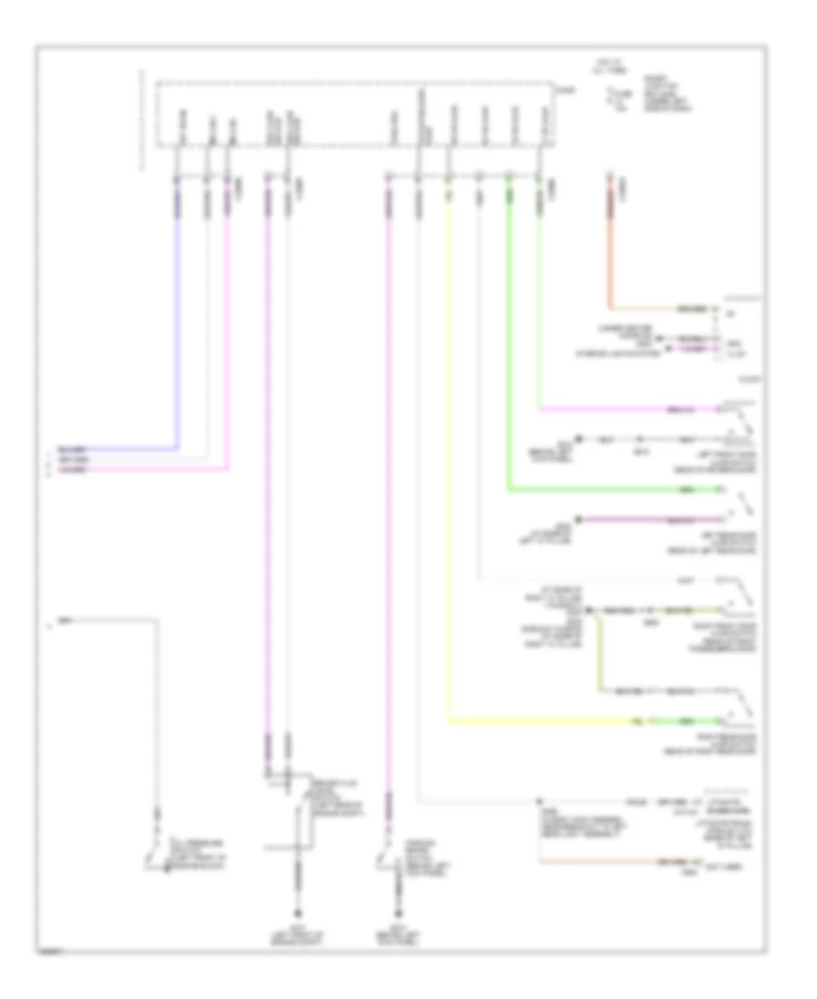
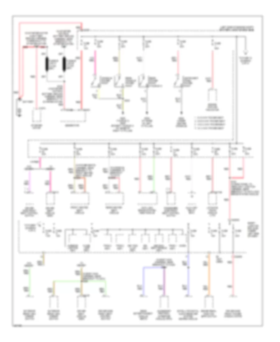
Power Distribution Wiring Diagram (1 of 4) for Ford Taurus X Limited 2008
List of elements for Power Distribution Wiring Diagram (1 of 4) for Ford Taurus X Limited 2008:
- (in body main harness, near breakout to c328) s364
- (in body main harness, near breakout to c510) s326
- (in starter motor & battery ground harness, in breakout to starter motor) s157
- (in starter motor & battery ground harness, near breakout to starter motor) s181
- (left side of engine compt) battery junction box (bjb)
- (not used)
- 3rd row seat enable (fet)
- Accessory protocol interface module (apim)
- Anti-lock brake system (abs) module
- Auxiliary relay box1
- Battery
- Brake pedal position (bpp) switch
- Bsi (fet)
- C102a
- C102b
- C1035
- C197a
- C2280d
- C2280g
- C341a
- C341b
- C4174b
- Console power point
- Driver seat module (dsm)
- Driver side front power window motor
- Driver side front seat control switch
- Engine cooling fan motor
- Exterior rear view mirror switch
- Floor lamp (fet)
- Front heated seat module
- Fuse 10a
- Fuse 15a
- Fuse 20a
- Fuse 30a
- Fuse 40a
- Fuse 50a
- Fuse 7.5a
- Fuse 80a
- G202 (under center console)
- G300 (taurus x) g305 (except taurus x) (at base of right "c" pillar)
- G302 (at base of left "c" pillar)
- Generator
- Instrument panel power point
- Interior lighting (fet)
- Key pad illum (fet)
- Liftgate/ trunk module (ltm)
- Micro
- Passenger side front seat control switch
- Rear console power point
- Rear entertainment module (retm)
- Rear heated seat module
- Rear power point (taurus x)
- Red
- S182 (in starter motor & battery ground harness, near breakout to starter motor)
- S183 (in dash panel to headlight junction harness, near breakout to anti-lock brake system module)
- S383
- Satellite digital audio receiver system (sdars) module
- Smart junction box (sjb) (under left side of dash)
- Starter motor
- To fuse 12 (diagram 2 of 4)
- To fuse 6 (diagram 3 of 4)
- Tpms 1 (fet)
- Tpms 2 (fet)
- Tpms 3 (fet)
- W/ 4 way power seat
- W/ 6 way power seat
- W/ memory
- W/o 4 way power seat
- W/o 6 way power seat
- W/o memory
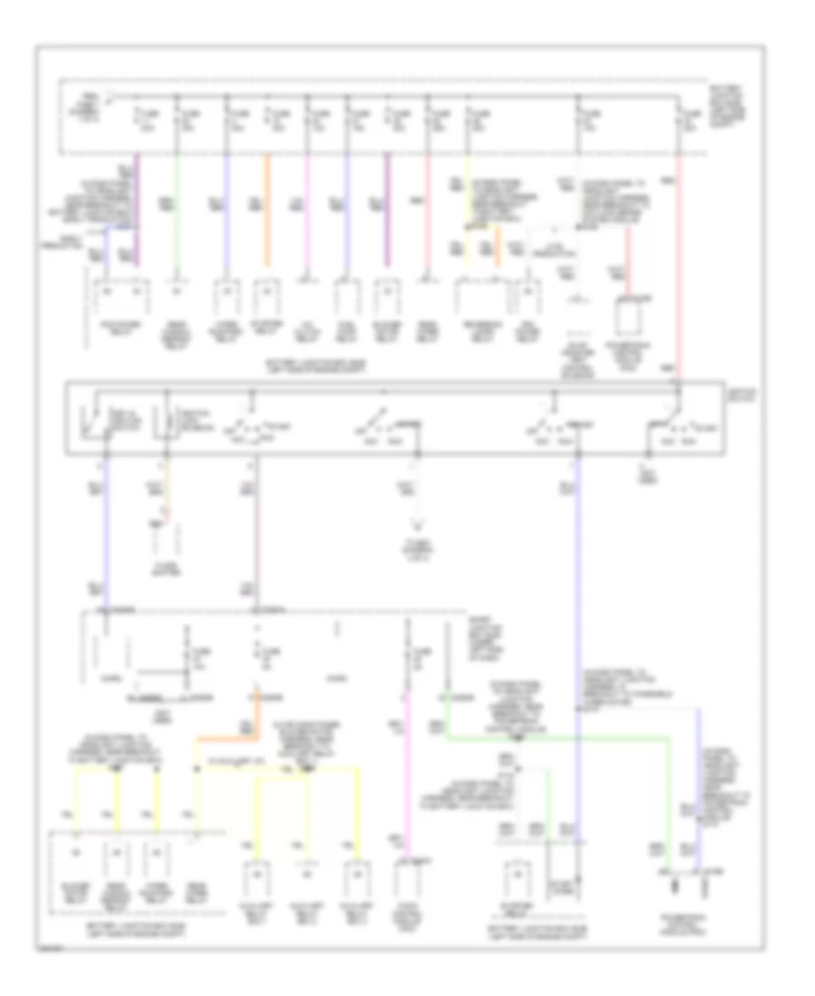
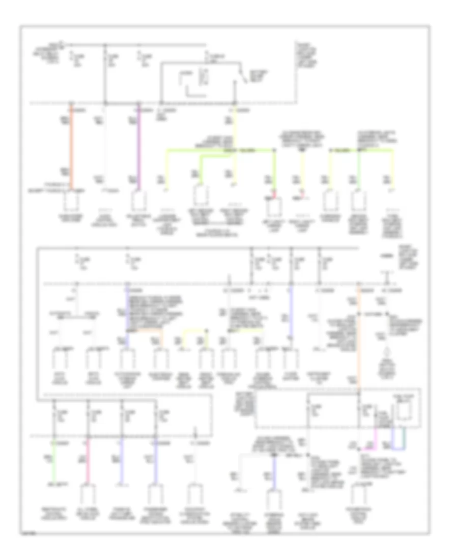
Power Distribution Wiring Diagram (2 of 4) for Ford Taurus X Limited 2008
List of elements for Power Distribution Wiring Diagram (2 of 4) for Ford Taurus X Limited 2008:
- (in air conditioner blower motor harness, near breakout to auxiliary relay box 1) s395
- (in dash panel to headlight junction harness, in breakout to windshield wiper motor) s170
- (in dash panel to headlight junction harness, near breakout to anti-lock brake system module) s162
- (in dash panel to headlight junction harness, near breakout to battery junction box) s167
- (in dash panel to headlight junction harness, near breakout to powertrain control module) s169
- (in dash panel to headlight junction harness, near breakout to powertrain control module) s174
- (not used)
- A/c clutch relay
- Acc
- Acc run
- Audio control module (acm)
- Auxiliary relay box 1
- Auxiliary relay box 2
- Auxiliary relay box 3
- Battery junction box (bjb) (left side of engine compt)
- Blower motor relay
- C175b
- C2280a
- C2280b
- C2280d
- C2280e
- C240a
- Early production
- Evap canister vent control solenoid
- Floor shifter
- From fuse 7 (diagram 1 of 4)
- Fuel pump relay
- Fuse 10a
- Fuse 15a
- Fuse 20a
- Fuse 25a
- Fuse 30a
- Fuse 40a
- Fuse 50a
- Fuse 5a
- Ignition lock solenoid
- Ignition switch
- Key in ignition switch
- Late production
- Micro
- Off
- Pcm power relay
- Powertrain control module (pcm)
- Rear window defrost relay
- Rear wiper relay
- Red
- Reversing lamps relay
- Run
- S116 (in dash panel to headlight junction harness, near breakout to battery junction box)
- Smart junction box (sjb) (under left side of dash)
- Smrc
- Start
- Start diode
- Starter relay
- To s221 (diagram 4 of 4)
- W/ auxiliary a/c
- Wiper run/park relay
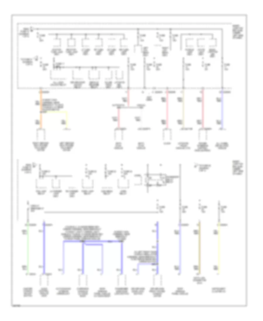
Power Distribution Wiring Diagram (3 of 4) for Ford Taurus X Limited 2008
List of elements for Power Distribution Wiring Diagram (3 of 4) for Ford Taurus X Limited 2008:
- (in body main harness, near breakout to c510) (taurus x w/ rear folding seats) s361
- (in body main harness, near breakout to c925) s318
- (in left front door window regulator harness, near breakout to exterior rearview mirror switch) s503
- (not used)
- (taurus x: in inside rearview mirror harness, near breakout to right vanity mirror light) (sable & taurus: in inside rearview mirror harness, near breakout to roof panel opening module) s908
- Accessory delay relay
- All lock/ unlock relay
- All wheel drive (awd) module
- Audio control module (acm)
- Auto-dimming interior mirror unit
- Automatic a/c
- Back- lighting led (fet)
- C2280a
- C2280b
- C2280d
- C228a
- C2357a
- C2368a
- C240a
- C4174b
- C504a
- Circuit breaker 47 30a
- Clock
- Data link connector (dlc)
- Datc hvac module
- Decklid release relay
- Driver door unlock relay
- Driver side door lock switch
- Driver side front power window motor
- Emtc hvac module
- Fog lamp relay
- From fuse 12 (diagram 1 of 4)
- From fuse 18 (diagram 3 of 4)
- Fuse 10a
- Fuse 15a
- Fuse 17 20a
- Fuse 20a
- Fuse 21 15a
- Fuse 22 15a
- Fuse 23 15a
- Fuse 24 20a
- Fuse 25a
- Fuse 5a
- High beam relay
- Horn relay
- Instrument cluster (ic)
- Left low beam (fet)
- Left second row power fold seat motor
- Lf turn lamp (fet)
- Lh corner lamp (fet)
- Liftgate rel (fet)
- Liftgate/ trunk module (ltm)
- Lr stop/ turn lamp (fet)
- Lr turn lamp (fet)
- Manual a/c
- Master window adjust switch
- Micro
- Overhead console (w/ moon roof)
- Park lamp relay
- Passenger side door lock switch
- Power steering control module (pscm)
- Puddle lamp (fet)
- Pulse train (fet)
- Rf turn lamp (fet)
- Rh corner lamp (fet)
- Right low beam (fet)
- Right second row power fold seat motor
- Roof opening panel module
- Roof opening panel module (w/ moon roof)
- Rr stop/ turn lamp (fet)
- Rr turn lamp (fet)
- Smart junction box (sjb) (under left side of dash)
- To fuse 21 (diagram 3 of 4)
- To fuse 38 (diagram 4 of 4)
- White light (fet)
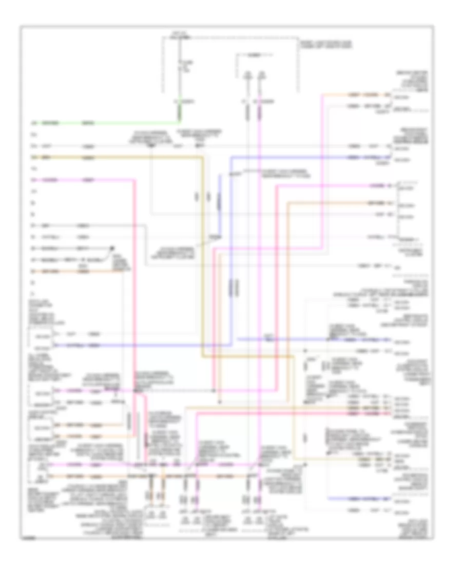
Power Distribution Wiring Diagram (4 of 4) for Ford Taurus X Limited 2008
List of elements for Power Distribution Wiring Diagram (4 of 4) for Ford Taurus X Limited 2008:
- (except taurus x)
- (in body main harness, near breakout to c510) s360
- (in inside rearview mirror harness, near breakout to right vanity mirror light) s901
- (in interior lights harness, near breakout to c9092) (taurus x) s910
- (in main harness, near breakout to smart junction box) (w/ advance trac ivd) s261
- (not used)
- (taurus x w/ rear folding seats)
- (taurus x)
- Adjustable pedal switch
- All wheel drive (awd) module
- Anti-lock brake system (abs) module
- Audio control module (acm)
- Auto-dimming interior mirror unit
- Automatic a/c
- Battery junction box (bjb) (left side of engine compt)
- Battery saver relay
- Breakout to battery junction box)
- C175b
- C2280a
- C2280b
- C2280d
- C2280e
- C228a
- C2357a
- C2368a
- C240a
- C310a
- C466a
- Datc hvac module
- Electronic compass
- Emtc hvac module
- Floor shifter
- From e accessory delay relay (diagram 3 of 4)
- From ignition switch (diagram 2 of 4)
- Front heated seat module
- Fuel pump motor diode
- Fuel pump relay
- Fuse 10a
- Fuse 20a
- Fuse 25 10a
- Fuse 5a
- Fuse 7.5a
- Harness, near breakout to c211) (w/ parking aid & heated seats s311
- Instrument cluster (ic)
- Left second row seat control switch
- Left vanity mirror lamp
- Luggage compartment lamp (taurus & sable)
- Manual a/c
- Micro
- Occupant classification system module (ocsm)
- Overhead console
- Parking aid module (pam)
- Passenger air bag deactivation (pad) indicator
- Passive anti-theft transceiver
- Power steering control module (pscm)
- Powertrain control module (pcm)
- Rear heated seat module
- Rearview mirror harness, near breakout to left vanity mirror light) (w/o microphone) s903
- Red
- Restraints control module (rcm)
- Right second row seat control switch
- Right vanity mirror lamp
- S161 (in dash panel to headlight junction harness, near breakout to anti-lock brake system module)
- S164 (in dash panel to headlight junction harness, near breakout to anti-lock brake system module)
- Second row seat interior/ map lamp assembly
- Smart junction box (sjb) (under left side of dash)
- Stability control sensor cluster (w/ advance trac ivd)
- Steering angle sensor module (sasm)
- Subwoofer amplifier
- Third row seat interior/ map lamp assembly (taurus x)
POWER DOOR LOCKS
Power Door Locks Wiring Diagram (1 of 2) for Ford Taurus X Limited 2008
List of elements for Power Door Locks Wiring Diagram (1 of 2) for Ford Taurus X Limited 2008:
- (behind left kick panel) g210
- (in body main harness, near breakout to c311) s330
- 1/2
- 3/4
- 5/6
- 7/8
- 9/0
- All lock/ unlock relay
- Antenna rke receiver
- C2280c
- C2280d
- Driver door unlock relay
- Fuse 20a
- G210 (behind left kick panel)
- G302 (at base of left "c" pillar)
- Hot at all times
- Interior lights system
- Internal rke/tpms
- Keypad switch assembly
- Left front door lock actuator (rear of driver's door)
- Left rear door lock actuator (rear of left rear door)
- Liftgate lock actuator (right side of liftgate)
- Liftgate rel (fet)
- Liftgate/glass ajar
- Micro
- Nca
- Right front door lock actuator (rear of front passenger's door)
- Right rear door lock actuator (rear of right rear door)
- S331 (in body main harness, near breakout to c311)
- S400
- S500
- Smart junction box (sjb) (under left side of dash)
Power Door Locks Wiring Diagram (2 of 2) for Ford Taurus X Limited 2008
List of elements for Power Door Locks Wiring Diagram (2 of 2) for Ford Taurus X Limited 2008:
- (in body main harness, near breakout to c925) s324
- Accessory delay relay
- Anti-theft
- Anti-theft hood switch (at left front corner of engine compt)
- C2280c
- C2280d
- C2280f
- Dr reset sw
- Driver door disarm switch
- Driver side door lock switch
- Fuse 15a
- G101 (left front of engine compt)
- G210 (behind left kick panel)
- G300 (taurus x) g305 (sable & taurus) (at base of right "c" pillar)
- G302 (at base of left "c" pillar)
- Hot at all times
- Left front door ajar switch (rear of driver's door)
- Left rear door ajar switch (rear of left rear door)
- Lf dr ajar
- Lock
- Lr dr ajar
- Micro
- Passenger side door lock switch
- Power windows system
- Rf dr ajar
- Right front door ajar switch (rear front of passenger's door)
- Right rear door ajar switch (rear of right rear door)
- Rr dr ajar
- S318
- S327 (in body main harness, near breakout to c925)
- S500
- S502
- S503
- S600
- Smart junction box (sjb) (under left side of dash)
- Trim lock
- Trim unlock
- Unlock
POWER MIRRORS
Electrochromic Mirror Wiring Diagram, with Microphone for Ford Taurus X Limited 2008
List of elements for Electrochromic Mirror Wiring Diagram, with Microphone for Ford Taurus X Limited 2008:
- (not used)
- Accessory protocol interface module (apim) (under center console)
- Audio control module (acm)
- Auto dimming interior mirror unit
- C2280d
- C240c
- Cbp41
- Cls10
- Dmn07
- Exterior lights system
- Fuse 15a
- G210 (behind left kick panel)
- Gd133
- Gnd
- Hot w/ accessory delay relay energized
- Mic+
- Mic-
- Nca
- Reverse
- Rmn02
- S902
- S908
- Shield
- Smart junction box (sjb) (under left side of dash)
- Vmn02
- Vpwr
- W/ sync
- W/o sync
Electrochromic Mirror Wiring Diagram, without Microphone for Ford Taurus X Limited 2008
List of elements for Electrochromic Mirror Wiring Diagram, without Microphone for Ford Taurus X Limited 2008:
- Auto dimming interior mirror unit
- C2280b
- Cbp31
- Cls10
- Exterior lights system
- Fuse 10a
- G210 (behind left kick panel)
- Gd133
- Gnd
- Hot in start or run
- Reverse
- S902
- S903
- Smart junction box (sjb) (under left side of dash)
- Vpwr
Power Mirrors Wiring Diagram, with Heated Mirrors for Ford Taurus X Limited 2008
List of elements for Power Mirrors Wiring Diagram, with Heated Mirrors for Ford Taurus X Limited 2008:
- (in left front door window regulator harness, near breakout to exterior rearview mirror switch) s501
- C2280d
- Defogger system
- Down
- Exterior rear view mirror switch
- Fuse 7.5a
- G210 (behind left kick panel)
- Hot at all times
- Interior lights system
- Left
- Left exterior rear view mirror (at mirror)
- Right
- Right exterior rear view mirror (at mirror)
- S502
- Select
- Smart junction box (sjb) (under left side of dash)
Power Mirrors Wiring Diagram, without Heated Mirrors for Ford Taurus X Limited 2008
List of elements for Power Mirrors Wiring Diagram, without Heated Mirrors for Ford Taurus X Limited 2008:
- (in left front door window regulator harness, near breakout to exterior rearview mirror switch) s501
- C2280d
- Down
- Exterior rear view mirror switch
- Fuse 7.5a
- G210 (behind left kick panel)
- G300 (taurus x) g305 (taurus & sable) (at base of right "c" pillar)
- Hot at all times
- Left
- Left exterior rear view mirror (at mirror)
- Right
- Right exterior rear view mirror (at mirror)
- S502
- S600
- Select
- Smart junction box (sjb) (under left side of dash)
POWER SEATS
Adjustable Pedal Wiring Diagram for Ford Taurus X Limited 2008
List of elements for Adjustable Pedal Wiring Diagram for Ford Taurus X Limited 2008:
- Adjustable pedal motor (under left side of dash)
- Adjustable pedal switch
- C2280a
- Forward
- Fuse 20a
- G202 (under center console)
- Hot at all times
- Illum
- Interior lights system
- Rearward
- S223
- Smart junction box (sjb) (under left side of dash)
Heated Seats Wiring Diagram, Front Seats for Ford Taurus X Limited 2008
List of elements for Heated Seats Wiring Diagram, Front Seats for Ford Taurus X Limited 2008:
- (at base of right "c" pillar) (taurus & sable) g305 (taurus x) g300
- (behind center of dash)
- (in power seats harness, near breakout to passenger safety belt buckle switch) s350
- Battery junction box (bjb) (left side of engine compt)
- C2280b
- C228b
- Cbp35
- Chs02
- Chs04
- Chs07
- Chs09
- Chs13
- Chs14
- Chs29
- Chs30
- Drv batt
- Drv heater feed
- Drv high led ind
- Drv high/low/off
- Drv low led ind
- Drv st ntc sense
- Front heated seat module (under front passenger's seat)
- Fuse 10a
- Fuse 20a
- G300 (taurus x) g305 (taurus & sable) (at base of right "c" pillar)
- G302 (at base of left "c" pillar)
- Gd148
- Gnd
- Hot at all times
- Hot in start or run
- Hvac module (datc)
- Left front seat back heater
- Left front seat cushion heater
- Nca
- Pass batt
- Pass heater feed
- Pass high led ind
- Pass high/low/off
- Pass low led ind
- Pass st ntc sense
- Return
- Rhs05
- Right front seat back heater
- Right front seat cushion heater
- Run/start
- S311
- S316
- S351
- S357
- Sbb22
- Smart junction box (sjb) (under left side of dash)
- Vhs26
- Vhs27
Heated Seats Wiring Diagram, Rear Seats for Ford Taurus X Limited 2008
List of elements for Heated Seats Wiring Diagram, Rear Seats for Ford Taurus X Limited 2008:
- (in body main harness, near breakout to c328) s397
- Backlighting
- Battery junction box (bjb) (left side of engine compt)
- C2280b
- Cbp35
- Chs39
- Chs43
- Chs46
- Chs47
- Chs48
- Chs49
- Chs50
- Chs51
- Chs52
- Chs53
- Drv batt
- Fuse 10a
- Fuse 20a
- G210 (behind left kick panel)
- G300 (at base of right "c" pillar)
- G302 (at base of left "c" pillar)
- Gd133
- Gnd
- High ind
- Hot at all times
- Hot in start or run
- Interior lights system
- Left rear seat back heater
- Left rear seat cushion heater
- Left rear seat heated seat switch
- Lh high les
- Lh low led
- Lh sys high/off
- Lh sys low/off
- Low ind
- Lr heater feed
- Lr st ntc sense
- Nca
- Off/ high
- Off/ low
- Pass batt
- Rear heated seat module (under center console)
- Return
- Rh high led
- Rh low led
- Rh sys high/off
- Rh sys low/off
- Rhs41
- Right rear seat back heater
- Right rear seat cushion heater
- Right rear seat heated seat switch
- Rr heater feed
- Rr st ntc sense
- Run/start
- S311
- S361
- S381
- S382
- Sbb05
- Smart junction box (sjb) (under left side of dash)
- Vhs42
- Vhs45
Power Seats Wiring Diagram, 2-Way Passenger Seat for Ford Taurus X Limited 2008
List of elements for Power Seats Wiring Diagram, 2-Way Passenger Seat for Ford Taurus X Limited 2008:
- (not used)
- Aft
- Battery junction box (bjb) (left side of engine compt)
- Down
- Front height
- Fuse 30a
- Fwd
- G300 (taurus x) g305 (taurus & sable) (at base of right "c" pillar)
- Horizontal
- Hot at all times
- Passenger seat horizontal motor (under front passenger's seat)
- Passenger side front seat control switch
- Rear height
- S316 (w/ heated seat)
Power Seats Wiring Diagram, 4-Way Passenger Seat for Ford Taurus X Limited 2008
List of elements for Power Seats Wiring Diagram, 4-Way Passenger Seat for Ford Taurus X Limited 2008:
- (not used)
- Aft
- Battery junction box (bjb) (left side of engine compt)
- Down
- Front height
- Fuse 30a
- Fwd
- G300 (taurus x) g305 (taurus & sable) (at base of right "c" pillar)
- Horizontal
- Hot at all times
- Lumbar
- Out
- Passenger seat horizontal motor (under front passenger's seat)
- Passenger seat recliner motor (under front passenger's seat)
- Passenger side front seat control switch
- Rear height
- Recline
- S316 (w/ heated seat)
Power Seats Wiring Diagram, 6-Way Driver Seat for Ford Taurus X Limited 2008
List of elements for Power Seats Wiring Diagram, 6-Way Driver Seat for Ford Taurus X Limited 2008:
- Aft
- Battery junction box (bjb) (left side of engine compt)
- Down
- Driver seat horizontal motor (under driver's seat)
- Driver side front seat control switch
- Front height
- Fuse 30a
- Fwd
- G302 (at base of left "c" pillar)
- Horizontal
- Hot at all times
- Rear height
- Seat front height motor (under driver's seat)
- Seat rear height motor (under driver's seat)
Power Seats Wiring Diagram, 8-Way Driver Seat for Ford Taurus X Limited 2008
List of elements for Power Seats Wiring Diagram, 8-Way Driver Seat for Ford Taurus X Limited 2008:
- (not used)
- Aft
- Battery junction box (bjb) (left side of engine compt)
- Down
- Driver seat horizontal motor (under driver's seat)
- Driver seat recliner motor (under driver's seat)
- Driver side front seat control switch
- Front height
- Fuse 30a
- Fwd
- G302 (at base of left "c" pillar)
- Horizontal
- Hot at all times
- Lumbar
- Out
- Rear height
- Recline
- S357 (w/heated seats)
- Seat front height motor (under driver's seat)
- Seat rear height motor (under driver's seat)
Second Row Folding Seat Wiring Diagram for Ford Taurus X Limited 2008
List of elements for Second Row Folding Seat Wiring Diagram for Ford Taurus X Limited 2008:
- Battery saver relay
- C2280d
- Fuse 10a
- Fuse 20a
- G300 (at base of right "c" pillar)
- G302 (at base of left "c" pillar)
- Hot at all times
- Left second row power fold seat motor (under left second row seat)
- Left second row seat control switch
- Micro
- Right second row power fold seat motor (under right second row seat)
- Right second row seat control switch
- S360
- S361
- Smart junction box (sjb) (under left side of dash)
POWER TOP/SUNROOF
Power Top/Sunroof Wiring Diagram for Ford Taurus X Limited 2008
List of elements for Power Top/Sunroof Wiring Diagram for Ford Taurus X Limited 2008:
- Accessory delay relay
- Auto
- C2280d
- Cbp41
- Close
- Common
- Cpr31
- Cpr38
- Cpr39
- Cpr40
- Del acc
- Fuse 15a
- Fuse 25a
- G210 (behind left kick panel)
- Gd133
- Gnd
- Hot at all times
- Micro
- Open
- Overhead console
- Roof opening panel module (center front of roof)
- S902
- S908
- Sbp19
- Smart junction box (sjb) (under left side of dash)
- Tilt up/ auto open
POWER WINDOWS
Power Windows Wiring Diagram for Ford Taurus X Limited 2008
List of elements for Power Windows Wiring Diagram for Ford Taurus X Limited 2008:
- Accessory delay relay
- Auto
- Batt
- C2280d
- C504a
- C504b
- Circuit breaker 30a
- Down
- Driver side front power window motor (in driver's door)
- Fuse 1 30a
- Fuse 15a
- G210 (behind left kick panel)
- Hot at all times
- Left front
- Left rear
- Left rear power window motor (in left rear door)
- Left rear window adjust switch
- Lock out
- Master window adjust switch
- Micro
- Passenger side front power window motor (in front passenger's door)
- Passenger side window adjust switch
- Red
- Right front
- Right rear
- Right rear power window motor (in right rear door)
- Right rear window adjust switch
- S323 (in body main harness, near breakout to c311)
- S500
- S502
- S503
- Smart junction box (sjb) (under left side of dash)
RADIO
Audiophile Sound Radio Wiring Diagram for Ford Taurus X Limited 2008
List of elements for Audiophile Sound Radio Wiring Diagram for Ford Taurus X Limited 2008:
- (at base of right "c" pillar) g305
- (taurus & sable: left side of luggage compt) (taurus x: behind right rear quarterpanel)
- Am ant
- Ant
- Ant pwr
- Antenna
- Antenna pwr
- Audio control module (acm)
- C2280a
- C2280b
- C2280d
- C240a
- C240b
- C240c
- C466a
- C466b
- Cbp28
- Cbp41
- Cme05
- Cme44
- Cmeo5
- Computer data lines system
- Delay/acc
- Dme22
- Early production
- Electronic hidden antenna module (eham) (sable & taurus: near base of right "c" pillar) (taurus x: top right of liftgate)
- Enbl
- Fm ant
- Fuse 28 5a
- Fuse 38 20a
- Fuse 39 20a
- Fuse 41 15a
- G200 (under center console)
- G300 (at base of right "c" pillar)
- G302 (at base of left "c" pillar)
- Gd103
- Gd148
- Gnd
- Hot at all times
- Hot in start
- Hot w/ accessory delay relay
- Late production taurus x
- Left front speaker
- Left rear speaker
- Left rear woofer
- Lf spkr +
- Lf spkr -
- Lr spkr +
- Lr spkr -
- Ms can +
- Ms can -
- Nca
- Out 1 +
- Out 1 -
- Out 2 +
- Out 2 -
- Pair wires
- Parking aid module (pam) (if equipped) (sable & taurus: left rear of luggage compt) (taurus x: top of right "c" pillar)
- Radio mute
- Rf spkr +
- Rf spkr -
- Right front speaker
- Right rear speaker
- Right rear woofer
- Rme01
- Rme02
- Rme07
- Rme09
- Rme10
- Rme12
- Rme22
- Rr spkr +
- Rr spkr -
- S387
- Sbp38
- Sbp39
- Shield
- Smart junction box (sjb) (under left side of dash)
- Sme23
- Start
- Sub +
- Sub -
- Sub enable
- Sub shield
- Subwoofer amplifier
- Taurus & sable
- Taurus x
- Twisted
- Vbatt
- Vdb06
- Vdb07
- Vme01
- Vme02
- Vme07
- Vme09
- Vme10
- Vme12
- Vme22
Base Radio Wiring Diagram for Ford Taurus X Limited 2008
List of elements for Base Radio Wiring Diagram for Ford Taurus X Limited 2008:
- Am ant
- Ant
- Ant pwr
- Antenna
- Antenna pwr
- Audio control module (acm)
- C2280a
- C2280b
- C240a
- C240b
- C240c
- Cbp28
- Cbp41
- Cme05
- Cme44
- Cmeo5
- Computer data lines system
- Delay/acc
- Early production
- Electronic hidden antenna module (eham) (sable & taurus: near base of right "c" pillar) (taurus x: top right of liftgate)
- Fm ant
- Fuse 28 5a
- Fuse 39 20a
- Fuse 41 15a
- G200 (under center console)
- Gd103
- Gnd
- Hot at all times
- Hot in start
- Hot w/ accessory delay relay
- Late production taurus x
- Left front speaker
- Left rear speaker
- Lf spkr +
- Lf spkr -
- Lr spkr +
- Lr spkr -
- Ms can +
- Ms can -
- Nca
- Pair wires
- Parking aid module (pam) (if equipped) (sable & taurus: left rear of luggage compt) (taurus x: top of right "c" pillar)
- Radio mute
- Rf spkr +
- Rf spkr -
- Right front speaker
- Right rear speaker
- Rme07
- Rme09
- Rme10
- Rme12
- Rr spkr +
- Rr spkr -
- Sbp39
- Shield
- Smart junction box (sjb) (under left side of dash)
- Start
- Twisted
- Vbatt
- Vdb06
- Vdb07
- Vme07
- Vme09
- Vme10
- Vme12
Premium Radio Wiring Diagram, with SYNC for Ford Taurus X Limited 2008
List of elements for Premium Radio Wiring Diagram, with SYNC for Ford Taurus X Limited 2008:
- (in body main harness, in breakout to satellite audio receiver system module)
- (in main harness, near breakout to in-vehicle temperature sensor)
- (in main harness, near breakout to instrument cluster) s218
- (not used)
- (sable & taurus: right side of luggage compt) (taurus x: behind right rear quarterpanel) satellite digital audio receiver system (sdars) module
- (taurus x: right rear corner of vehicle) (sable & taurus: at base of left "c" pillar) g400
- Accessory protocol interface module (apim) (under center console)
- Audio control module (acm)
- Audio jack
- Auto-dimming interior mirror unit
- C218a
- C218b
- C2280a
- C2280d
- C290a
- C290c
- Clockspring (in steering wheel)
- Cmm14
- Cmm15
- Computer data lines system
- Dme41
- Dme45
- Dmn07
- Dmn14
- Fuse 3 15a
- Fuse 39 20a
- G202 (under center console)
- Gd114
- Gnd
- Gnd2
- Hot at all times
- Hs can +
- Hs can -
- In 2l +
- In 2l -
- In 2r +
- In 2r -
- Info
- Instrument cluster
- Interior lights system
- Menu +
- Menu -
- Message sig
- Mic +
- Mic -
- Mono +
- Mono -
- Ms can +
- Ms can -
- Nca
- Nca nca
- Out l +
- Out l -
- Out r +
- Out r -
- Pair wires
- Phone
- Reset
- Right steering wheel switch
- Rmc27
- Rme41
- Rme42
- Rme45
- Rme46
- Rmn02
- Rmn14
- S231
- S232
- S364
- S399
- S470
- Sbp03
- Sbp39
- Setup
- Shield
- Smart junction box (sjb) (under left side of dash)
- Stereo 1l +
- Stereo 1l -
- Stereo 1r +
- Stereo 1r -
- Stereo l +
- Stereo l -
- Stereo r +
- Stereo r -
- Swc1 -
- Swc2 +
- Swc2 -
- Talk
- Twisted
- Usb
- Usb port
- Vbatt
- Vdb04
- Vdb05
- Vdb06
- Vdb07
- Vme41
- Vme42
- Vme45
- Vme46
- Vmn02
- Vmn14
- Vnm02
- Vnm14
Premium Radio Wiring Diagram, without SYNC (1 of 2) for Ford Taurus X Limited 2008
List of elements for Premium Radio Wiring Diagram, without SYNC (1 of 2) for Ford Taurus X Limited 2008:
- Antenna
- Antenna pwr
- Audio control module (acm)
- Audio jack
- Audiophile sound radio circuit
- Auto-dimming interior mirror unit (w/ microphone)
- C2280a
- C2280b
- C240a
- C240b
- C240c
- Cbp28
- Cbp41
- Cme05
- Cme44
- Cmeo5
- Computer data lines system
- Delay/acc
- Dme22
- Dme45
- Dmn07
- Fuse 28 5a
- Fuse 39 20a
- Fuse 41 15a
- G200 (under center console)
- Gd103
- Gnd
- Hot at all times
- Hot in start
- Hot w/ accessory delay relay
- In 2l +
- In 2l -
- In 2r +
- In 2r -
- Left front speaker
- Left rear speaker
- Lf spkr +
- Lf spkr -
- Lr spkr +
- Lr spkr -
- Mic +
- Mic -
- Ms can +
- Ms can -
- Mute radio
- Nca
- Pair wires
- Parking aid module (pam) (sable & taurus: left rear of luggage compt) (taurus x: top of right "c" pillar)
- Radio mute
- Rf spkr +
- Rf spkr -
- Right front speaker
- Right rear speaker
- Rmc27
- Rme07
- Rme09
- Rme10
- Rme12
- Rme22
- Rme45
- Rme46
- Rmn02
- Rr spkr +
- Rr spkr -
- Sbp39
- Shield
- Smart junction box (sjb) (under left side of dash)
- Sme23
- Start
- Sub +
- Sub -
- Sub enable
- Sub shield
- Swc1 +
- Swc1 -
- Twisted
- Vbatt
- Vdb06
- Vdb07
- Vme07
- Vme09
- Vme10
- Vme12
- Vme14
- Vme22
- Vme45
- Vme46
- Vmn02
Premium Radio Wiring Diagram, without SYNC (2 of 2) for Ford Taurus X Limited 2008
List of elements for Premium Radio Wiring Diagram, without SYNC (2 of 2) for Ford Taurus X Limited 2008:
- (in main harness, near breakout to instrument cluster) s218
- Am ant
- Ant
- Ant pwr
- C218a
- C218b
- Clockspring (in steering wheel)
- Computer data lines system
- Early production
- Electronic hidden antenna module (eham) (sable & taurus: near base of right "c" pillar) (taurus x: top right of liftgate)
- Fm ant
- Info
- Instrument cluster
- Interior lights system
- Late production taurus x
- Media
- Message sig
- Ms can +
- Ms can -
- Mute
- Nca
- Reset
- Right steering wheel switch
- Seek +
- Seek -
- Setup
- Shield
- Swc1 -
- Talk
- Vol +
- Vol -
- W/ navigation
- W/o navigation
Rear Entertainment Radio Wiring Diagram (1 of 2) for Ford Taurus X Limited 2008
List of elements for Rear Entertainment Radio Wiring Diagram (1 of 2) for Ford Taurus X Limited 2008:
- (in body main harness, in breakout to satellite audio receiver system module)
- (sable & taurus: right side of luggage compt) (taurus x: behind right rear quarterpanel) satellite digital audio receiver system (sdars) module
- (taurus x: right rear corner of vehicle) (sable & taurus: at base of left "c" pillar) g400
- Ant
- C218a
- C218b
- C2280a
- C2280d
- Clockspring (in steering wheel)
- Computer data lines system
- Dme41
- Fuse 3 15a
- Fuse 39 20a
- Gd103
- Gnd
- Hot at all times
- Info
- Instrument cluster
- Interior lights system
- Left rear speaker
- Lr spkr +
- Lr spkr -
- Menu +
- Menu -
- Message sig
- Ms can +
- Ms can -
- Nca
- Nca nca
- Out l +
- Out l -
- Out r +
- Out r -
- Pair wires
- Phone
- R+ out
- R- out
- Rear entertainment module (retm)
- Reset
- Right rear speaker
- Right steering wheel switch
- Rme09
- Rme12
- Rme41
- Rme42
- Rme58
- Rme59
- Rr spkr +
- Rr spkr -
- S218 (in main harness, near breakout to instrument cluster)
- S364
- S470
- Satellite radio antenna
- Sbp03
- Setup
- Shield
- Smart junction box (sjb) (under left side of dash)
- Stereo 1 l+
- Stereo 1 l-
- Stereo 1r +
- Stereo 1r -
- Stereo 2 l +
- Stereo 2 l -
- Stereo l +
- Stereo l -
- Stereo r +
- Stereo r -
- Swc1 -
- Talk
- Twisted
- Vbatt
- Vdb06
- Vdb07
- Vme09
- Vme12
- Vme41
- Vme42
- Vme58
- Vme59
- W/ satellite receiver & w/o sync
- W/o satellite receiver & w/ sync
Rear Entertainment Radio Wiring Diagram (2 of 2) for Ford Taurus X Limited 2008
List of elements for Rear Entertainment Radio Wiring Diagram (2 of 2) for Ford Taurus X Limited 2008:
- (in main harness, near breakout to in-vehicle temperature sensor)
- (under center console) g202
- Accessory protocol interface module (apim) (under center console)
- Audio control module (acm)
- Audio jack
- Auto-dimming interior mirror unit
- C240c
- C290a
- C290c
- Cmm14
- Cmm15
- Computer data lines system
- Dme41
- Dme45
- Dmn07
- Dmn14
- Gd114
- Gnd
- Gnd2
- Hs can +
- Hs can -
- In 2l +
- In 2l -
- In 2r +
- In 2r -
- Lr spkr +
- Mic +
- Mic -
- Mono +
- Mono -
- Ms can +
- Ms can -
- Nca
- Rmc27
- Rme09
- Rme12
- Rme41
- Rme42
- Rme45
- Rme46
- Rme58
- Rme59
- Rmn02
- Rmn14
- Rr sprk +
- Rr sprk -
- S231
- S232
- S399
- Sbp03
- Sbp39
- Shield
- Stereo 1l +
- Stereo 1l -
- Stereo 1r +
- Stereo 1r -
- Stereo 2 l +
- Stereo 2 l -
- Stereo 2 r +
- Stereo 2 r -
- Stereo l +
- Stereo l -
- Stereo r +
- Stereo r -
- Swc1 -
- Swc2 +
- Swc2 -
- Swc2 rtn
- Usb
- Usb port
- Vbatt
- Vdb04
- Vdb05
- Vdb06
- Vdb07
- Vme09
- Vme12
- Vme41
- Vme42
- Vme45
- Vme46
- Vme58
- Vme59
- Vmn02
- Vmn14
- Vnm02
- Vnm14
SHIFT INTERLOCK
Shift Interlock Wiring Diagram for Ford Taurus X Limited 2008
List of elements for Shift Interlock Wiring Diagram for Ford Taurus X Limited 2008:
- Battery junction box (bjb) (left side of engine compt)
- Boo
- Brake pedal position (bpp) switch (under left side of dash)
- Bsi
- C2280b
- C2280c
- C2280d
- Control
- Engine controls system
- Exterior lights system
- Fet
- Floor
- Fuse 10a
- Fuse 15a
- Fuse 20a
- G202 (under center console)
- Hot at all times
- Ignition
- Ignition switch
- Interior lights system
- Key
- Key in ignition
- Lock
- Micro
- N d
- Red
- S213 (in dash panel to headlight junction harness, in breakout to c210)
- Shifter
- Smart junction box (sjb) (under left side of dash)
- Switch
- Transmission
- Transmissions system
STARTING/CHARGING
Charging Wiring Diagram for Ford Taurus X Limited 2008
List of elements for Charging Wiring Diagram for Ford Taurus X Limited 2008:
- Battery
- Battery junction box (bjb) (left side of engine compt)
- C175b
- C2280a
- Cdc10
- Cdc15
- Computer data lines system
- Fuse 10a
- G103 (left front of engine compt)
- G104 (right rear of engine)
- G202 (under center console)
- Gem com
- Gem mon
- Generator
- Hot at all times
- Hs can+
- Hs can-
- Instrument cluster
- Powertrain control module (pcm) (rear of engine compt)
- Pwr gnd
- Red
- S157
- S181
- S182
- Smart junction box (under left side of dash)
- Starter motor
- Vbatt
- Vdb04
- Vdb05
Starting Wiring Diagram for Ford Taurus X Limited 2008
List of elements for Starting Wiring Diagram for Ford Taurus X Limited 2008:
- 6f transmission (left side of transmission)
- Acc
- Battery
- Battery junction box (bjb) (left side of engine compt)
- C175b
- C175t
- Cdc12
- Cdc35
- Ce336
- Charging circuit
- Computer data lines system
- Fuse 20a
- Fuse 30a
- G103 (left front of engine compt)
- G104 (right rear of engine)
- Ignition switch
- Off
- Power distribution system
- Powertrain control module (pcm) (rear of engine compt)
- Red
- Run
- S116
- S157
- S169
- S170
- S174
- Start
- Start diode
- Starter motor
- Starter relay
- Tr1
- Tr2
- Tr3
- Tr4
- Vdb04
- Vdb05
- Vet29
- Vet30
- Vet31
- Vet32
SUPPLEMENTAL RESTRAINTS
Supplemental Restraints Wiring Diagram (1 of 2) for Ford Taurus X Limited 2008
List of elements for Supplemental Restraints Wiring Diagram (1 of 2) for Ford Taurus X Limited 2008:
- C218a
- C256a
- C256b
- C310a
- C310b
- Can +
- Can -
- Cbp32
- Clockspring (in steering column)
- Computer data lines system
- Cr101
- Cr102
- Cr103
- Cr104
- Cr105
- Cr106
- Cr109
- Cr111
- Cr146
- Cr147
- Cr163
- Cr164
- Cr201
- Cr203
- Dr 1 feed
- Dr 1 rtn
- Dr 2 feed
- Dr 2 rtn
- Dr ab1 feed
- Dr ab1 rtn
- Dr ab2 feed
- Dr ab2 rtn
- Dr bckl feed
- Dr bckl rtn
- Dr crtn feed
- Dr crtn rtn
- Dr imp sns
- Dr load feed
- Dr load rtn
- Dr sab feed
- Dr sab rtn
- Dr trck pos
- Driver air bag module (in steering wheel)
- Driver safety belt buckle pretensioner (under driver's seat)
- Driver seat safety belt load limiting retractor (base of left "b" pillar)
- Driver side impact sensor 1 (in driver's door)
- G210 (behind left kick panel)
- Nca
- Pad lp
- Passenger air bag module (behind right side of dash)
- Passenger safety belt buckle pretensioner (under front passenger's seat)
- Passenger seat safety belt load limiting retractor (base of right "b" pillar)
- Passenger side impact sensor 1 (in front passenger's door)
- Pin shorting bar is engaged when module connector is disconnected from harness. (shorting bars are connected between the following pins: 1-2, 3-4, 5-6, & 13-14 c310a 1-2, 7-8, 9-10,, 21-22 c310b
- Ps 1 feed
- Ps 1 rtn
- Ps 2 feed
- Ps 2 rtn
- Ps ab1 feed
- Ps ab1 rtn
- Ps ab2 feed
- Ps ab2 rtn
- Ps bckl feed
- Ps bckl rtn
- Ps belt sw
- Ps crtn feed
- Ps crtn rtn
- Ps imp sns
- Ps load feed
- Ps load rtn
- Ps sab feed
- Ps sab rtn
- Ps trck pos
- Restraints control module (rcm) (under center console)
- Right front impact sensor (behind right side of front bumper)
- Rr101
- Rr102
- Rr103
- Rr104
- Rr105
- Rr106
- Rr109
- Rr111
- Rr116
- Rr129
- Rr130
- Rr131
- Rr132
- Rr133
- Rr134
- Rr146
- Rr147
- Rr163
- Rr164
- Run/strt
- S368
- S369
- Shorting bar
- Trck feed
- Vdb04
- Vdb05
- Vr213
- Vr214
- Vr215
- Vr216
- Vr217
- Vr218
- Vr219
- Vr220
Supplemental Restraints Wiring Diagram (2 of 2) for Ford Taurus X Limited 2008
List of elements for Supplemental Restraints Wiring Diagram (2 of 2) for Ford Taurus X Limited 2008:
- (under front passenger's seat) occupant classification system (ocs) module
- Bts rtn
- Bts sig
- C2280b
- C2280d
- Can +
- Can -
- Cbp46
- Computer data lines system
- Cr153
- Driver safety canopy module (in left "c" pillar) (except taurus x) (top of left "d" pillar) (taurus x)
- Driver seat position sensor (under driver's seat)
- Driver side air bag module (under driver's seat)
- Driver side impact sensor 2 (in left "c" pillar)
- Except taurus x
- Fuse 10a
- Fuse 7.5a
- G210 (behind left kick panel)
- Gd133
- Gnd
- Hot in run or start
- Left front impact sensor (behind left side of front bumper)
- Lr142
- Passenger air bag deactivation pad indicator
- Passenger safety belt tension sensor (under front passenger's seat)
- Passenger safety canopy module (in right "c" pillar) (except taurus x) (top of right "d" pillar) (taurus x)
- Passenger seat position sensor (under front passenger's seat)
- Passenger side air bag module (under front passenger's seat)
- Passenger side impact sensor 2 (in right "c" pillar)
- Rr142
- Rr153
- Run/strt
- S368
- S369
- Seat pressure sensor (under front passenger's seat)
- Shorting bar
- Smart junction box (sjb) (under left side of dash)
- Sns rtn
- Sws v-in
- Swsv-out
- Taurus x
- Vdb04
- Vdb05
- Vr210
- Vr223
- Vref1
TRANSMISSION
A/T Wiring Diagram for Ford Taurus X Limited 2008
List of elements for A/T Wiring Diagram for Ford Taurus X Limited 2008:
- (in dash panel to headlight junction harness, in breakout to 6f transmission)
- (left side of transmission) 6f transmission
- Accelerator pedal position (app) sensor (top of accelerator pedal assembly)
- App1
- App1vref
- App2
- App2vref
- App3
- Appsrtn1
- Appsrtn2
- Battery junction box (bjb) (left side of engine compt)
- Boo
- Brake pedal position (bpp) switch (under left side of dash)
- C175b
- C175e
- C175t
- Ccb08
- Ce412
- Ce426
- Cet05
- Cet06
- Cet07
- Cet08
- Cet09
- Cet10
- Cet19
- Cet25
- Cet34
- Cls28
- Computer data lines system
- Electronic throttle control (etc) (top rear of engine)
- Etcref
- Exterior lights system
- Floor shifter
- Fuse 10a
- Fuse 15a
- Fuse 20a
- Fuse 5a
- G102 (right rear side of engine compt)
- Gd113
- Hot at all times
- Hot in run or start
- Kapwr
- Le111
- Le134
- Le136
- Le137
- Lpc
- Ms can+
- Ms can-
- Oss
- Overdrive cancel
- Powertrain control module (pcm) (rear of engine compt)
- Pwr gnd1
- Pwr gnd2
- Re134
- Re136
- Re137
- Re406
- Ret24
- Rev lmps ctrl
- Reversing lamps relay
- S118
- S162
- S173
- Sbb23
- Smart junction box (sjb) (under left side of dash)
- Ssa
- Ssb
- Ssc
- Ssd
- Sse
- Tacm+
- Tacm-
- Tcc
- Tft
- Tft sig rtn
- Tp1 ns
- Tp2 ps
- Tprtn
- Tr gnd
- Tr-1
- Tr-2
- Tr-3
- Tr-4
- Transmission control switch
- Tspc
- Tss
- Tss/oss gnd
- Tss/oss tr gnd
- Tss/oss vpwr
- Vdb06
- Vdb07
- Ve701
- Ve702
- Ve703
- Ve818
- Ve819
- Vet26
- Vet27
- Vet29
- Vet30
- Vet31
- Vet32
- Vet33
AWD Wiring Diagram for Ford Taurus X Limited 2008
List of elements for AWD Wiring Diagram for Ford Taurus X Limited 2008:
- Active torque control coupling (atcc) solenoid (under center rear of vehicle)
- All wheel drive (awd) module (behind right kick panel)
- C2280b
- C2280d
- Cbp34
- Ccf21
- Computer data lines system
- Fuse 10a
- Fuse 5a
- G300 (taurus x) g305 (taurus & sable) (at base of right "c" pillar)
- Gd148
- Gnd
- Hot at all times
- Hot in run or start
- Hs can +
- Hs can -
- Nca
- Rcf21
- Sbp11
- Smart junction box (sjb) (under left side of dash)
- Sol +
- Sol -
- Vbatt
- Vdb04
- Vdb05
- Vpwr
TRUNK, TAILGATE, FUEL DOOR
Power Liftgate Wiring Diagram for Ford Taurus X Limited 2008
List of elements for Power Liftgate Wiring Diagram for Ford Taurus X Limited 2008:
- (at base of left "c" pillar) g302
- (in rear window wiper motor feed harness, near breakout to rear wiper motor assembly) s408
- (not used)
- 10a
- 20a
- 30a
- Battery junction box (bjb) (left side of engine compt)
- C2280c
- C2280e
- C4174a
- C4174b
- Center stack switch assembly
- Chime
- Chime rtn
- Cinch
- Cinch motor
- Close sw sector gear open
- Clutch
- Computer data lines system
- Console open/
- Cpl10
- Cpl58
- Cpr51
- Cpr55
- Cpr56
- Cpr57
- Cpr58
- Cpr61
- Cpr62
- Cpr63
- Cpr64
- Cpr65
- Cpr66
- Cpr67
- Cpr68
- Cpr69
- Encoder 1
- Encoder 2
- Encoder 5v
- Encoder rtn
- Exterior lights system
- Fuse
- G202 (under center console)
- G300 (at base of right "c" pillar)
- G302 (at base of left "c" pillar)
- Gd147
- Gnd
- Hall effect sensor
- Hot at all times
- Latch sw full
- Latch sw half
- Left liftgate obstacle detection strip (at left side of liftgate)
- Lh pinch strip
- License lamps/ liftgate release switch
- Liftgate
- Liftgate drive motor assembly (base of left "d" pillar)
- Liftgate latch/ unlatch assembly (right side of liftgate)
- Liftgate rel (fet)
- Liftgate release
- Liftgate sw
- Liftgate switch
- Liftgate/ glass ajar
- Liftgate/glass ajar
- Liftgate/trunk module (ltm) (base of left "d" pillar)
- Micro
- Motor close 1
- Motor open 1
- Ms can+
- Ms can-
- Nca
- Pawl sw sig
- Pinch sensor rtn
- Power liftgate chime (base of left "d" pillar)
- Rear interior sw
- Rh pinch strip
- Right liftgate obstacle detection strip (at right side of liftgate)
- Rpr52
- Rpr55
- Rpr56
- S366 (in body main harness, near breakout to left rear light assembly)
- S400
- Sbb29
- Sbp14
- Sector gear close
- Smart junction box (sjb) (under left side of dash)
- Un cinch
- Vbatt
- Vdb06
- Vdb07
- Vpr53
- Vpr54
Trunk Release Wiring Diagram for Ford Taurus X Limited 2008
List of elements for Trunk Release Wiring Diagram for Ford Taurus X Limited 2008:
- Battery saver relay
- C2280c
- C2280d
- Decklid ajar sw
- Decklid latch assembly (center rear of decklid)
- Decklid release relay
- Decklid release switch
- Decklid sw
- Fuse 10a
- Fuse 20a
- G202 (under center console)
- G302 (at base of left "c" pillar)
- Hot at all times
- Illumination
- Interior lights system
- Luggage compartment lamp
- Micro
- S360
- Smart junction box (sjb) (under left side of dash)
WARNING SYSTEMS
Chime Wiring Diagram for Ford Taurus X Limited 2008
List of elements for Chime Wiring Diagram for Ford Taurus X Limited 2008:
- Auto
- Battery junction box (bjb) (left side of engine compt)
- Brake fluid level switch (on brake fluid reservoir)
- Brk fluid sw
- C2280b
- C2280c
- C2280d
- C2280f
- C310a
- C310b
- Cbp32
- Computer data lines system
- Cr163
- Cr201
- Driv brk feed
- Driv buckle rtn
- Driv buckle sw
- Driver safety belt buckle switch (under driver's seat)
- Fog lamp
- Fuse 10a
- Fuse 20a
- Fuse 5a
- G101 (left front of engine compt)
- G202 (under center console)
- G210 (behind left kick panel)
- G300 (at base of right "c" pillar)
- G302 (at base of left "c" pillar)
- Gnd
- Headlamp switch
- Hot at all times
- Hot in start or run
- Hs can+
- Hs can-
- Ignition switch
- Instrument cluster (ic)
- Key in ign
- Key in ignition
- Left front door ajar switch (rear of driver's door)
- Left rear door ajar switch (rear of left rear door)
- Left turn
- Lf door ajar
- Lo beam
- Lr door ajar
- Ms can +
- Ms can -
- Ms can+
- Ms can-
- Multifunction switch
- Nca
- Off
- Park
- Park brake
- Parking brake switch (behind left kick panel)
- Red
- Restraints control module (rcm) (under center console)
- Rf door ajar
- Right front door ajar switch (rear of front passenger's door)
- Right rear door ajar switch (rear of right rear door)
- Right turn
- Rr door ajar
- Rr163
- Run/start
- Smart junction box (sjb) (under left side of dash)
- Vdb04
- Vdb05
- Vpwr
Tire Pressure Monitoring Wiring Diagram for Ford Taurus X Limited 2008
List of elements for Tire Pressure Monitoring Wiring Diagram for Ford Taurus X Limited 2008:
- C2280d
- Fuse 10a
- G210 (behind left kick panel)
- Hot at all times
- Internal rke/ tpms antenna
- Left front tire pressure sensor
- Left rear tire pressure sensor
- Logic gnd
- Micro
- Pwr gnd
- Right front tire pressure sensor
- Right rear tire pressure sensor
- Smart junction box (sjb) (under left side of dash)
- Tpms receiver
- Vbatt
WIPER/WASHER
Front Wiper/Washer Wiring Diagram for Ford Taurus X Limited 2008
List of elements for Front Wiper/Washer Wiring Diagram for Ford Taurus X Limited 2008:
- (not used)
- 1) off 2) int 1 3) int 2 4) int 3 5) int 4 6) int 5 7) low 8) high
- Battery junction box (bjb) (left side of engine compt)
- C2280b
- C2280e
- C2280f
- Electronics
- Front wash switch
- Front washer relay
- Front wiper
- Fuse 29 5a
- Fuse 30a
- Fuse 45 5a
- G100 (right front of engine compt)
- G101 (left front of engine compt)
- G200 (under center console)
- Hall sensor
- Hi/lo speed relay
- Hot at all times
- Hot in run or acc
- Hot in run or start
- Instrument cluster (ic)
- Low washer
- Multi-function switch
- Rear washer relay
- Rear wiper motor assembly
- Run/ park
- Run/ park relay
- Run/park wiper relay
- S121 (in dash panel to headlight junction harness, in breakout to windshield wiper motor)
- S167
- S223
- Smart junction box (sjb) (under left side of dash)
- Taurus sable
- Taurus x
- Vpwr
- Washer fluid level switch
- Windshield washer pump motor
- Windshield wiper motor (left rear of engine compt)
- Wiper status
Rear Wiper/Washer Wiring Diagram for Ford Taurus X Limited 2008
List of elements for Rear Wiper/Washer Wiring Diagram for Ford Taurus X Limited 2008:
- (in rear window wiper motor feed harness, near breakout to rear wiper motor assembly) s401
- (not used)
- 1) off
- 2) int
- 3) on
- 4) rear wash
- Battery junction box (bjb) (left side of engine compt)
- C2280e
- Electronics
- Front washer relay
- Fuse 25a
- Fuse 45 5a
- G100 (right front of engine compt)
- G101 (left front of engine compt)
- G202 (under center console)
- G210 (behind left kick panel)
- G302 (at base of left "c" pillar)
- Hot at all times
- Hot in run or acc
- Multi-function switch
- Rear washer relay
- Rear wiper motor assembly (center of liftgate)
- Rear wiper relay
- Rear wiper switch
- Red
- S167
- S175
- S223
- S400
- Smart junction box (sjb) (under left side of dash)
- Windshield washer pump motor
- Windshield wiper motor (left rear of engine compt)

 Čeština
 Dansk
Dansk Deutsch
 Ελληνικά
 English
 English
 Español
 Suomi
Suomi Français
 Français
 עברית
עברית Hrvatski
 Magyar
 日本語
日本語 한국어
한국어 Nederlands
 Polski
 Português
 Português
 Română
 Русский
 Slovenčina
 Slovenščina
 Svenska
 Türkçe
 中文 (中国)