AIR CONDITIONING
Compressor Wiring Diagram for GMC Canyon 2012
 https://portal-diagnostov.com/license.html
Automotive Electricians Portal FZCO
Automotive Electricians Portal FZCO
https://portal-diagnostov.com/license.html
https://portal-diagnostov.com/license.html
Automotive Electricians Portal FZCO
Automotive Electricians Portal FZCO
List of elements for Compressor Wiring Diagram for GMC Canyon 2012:
- 5v ref
- A/c cltch diode
- A/c cmprsr fuse 10a
- A/c compressor clutch (5.3l: front of engine) (except 5.3l: left front of engine)
- A/c refrigerant pressure sensor (right rear of engine compt)
- A/c relay
- Clutch rly ctrl
- Engine control module (ecm) (right rear of engine compt)
- F11
- G103 (lower left side of engine)
- Ground distribution system
- Hot at all times
- Hot w/ run/crnk relay energized
- Ign fuse 15a
- Low ref
- Press sens
- Underhood fuse block (left front side of engine compt)
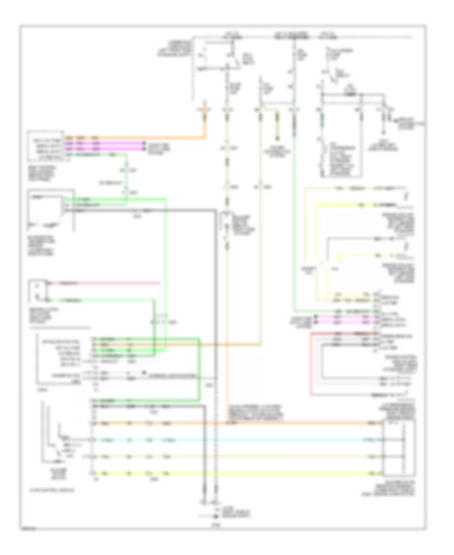
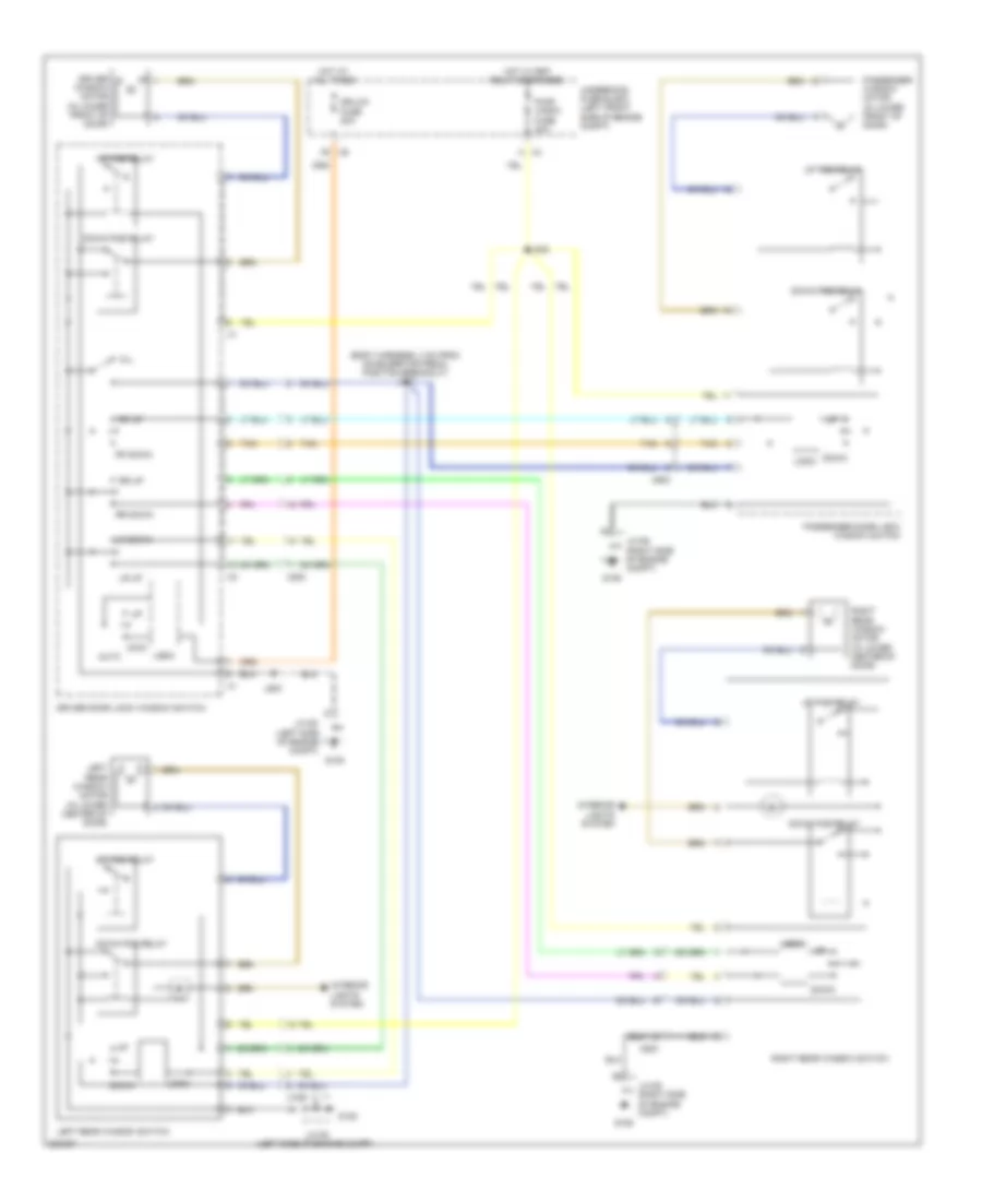
Manual A/C Wiring Diagram for GMC Canyon 2012
List of elements for Manual A/C Wiring Diagram for GMC Canyon 2012:
- (hvac harness, 14 cm from recirculation actuator breakout toward blower motor resistor assembly) j202
- 5.3l
- 5v ref
- A/c cltch diode
- A/c cmprsr fuse 10a
- A/c compressor clutch (5.3l: front of engine) (except 5.3l: left front of engine)
- A/c fuse 10a
- A/c refrigerant pressure sensor (right rear of engine compt)
- A/c relay
- A/c req sig
- A26
- A42
- A43
- A47
- B x4
- Blower motor (below right side of dash)
- Blower motor resistor assembly (lower right side of dash, near blower motor)
- Blower motor switch
- Blwr fuse 30a
- Body control module (bcm) (behind right kick panel)
- Computer data lines system
- Dimmer sw sig
- Dr ctrl a
- Dr ctrl b
- Engine control module (ecm) (right rear of engine compt)
- Engine coolant temperature (ect) sensor (left side of engine)
- Engine coolant temperature (ect) sensor (on left rear of engine)
- Evaporator temperature sensor (lower right side of dash)
- Except 5.3l
- F x203
- F10 x7
- F11
- G103 (lower left side of engine)
- G106
- Gnd
- Ground distribution system
- High
- Hot at all times
- Hot w/ run/crnk relay energised
- Hvac control module
- Ign 3 hvac relay
- Ign 3 voltage
- Ign fuse 15a
- Ign voltage
- Interior lights system
- J200
- Jx106 (right side of engine compt)
- Logic
- Low
- Low ref
- Nca
- Off
- Off blwr mtr ctrl
- Power distribution system
- Press sens sig
- Recirculation actuator (right side of dash)
- Rly ctrl
- Sens sig
- Serial data
- Tan
- Underhood fuse block (left front side of engine compt)
- X200
- X201
- X203
- X7 f5
ANTI-LOCK BRAKES
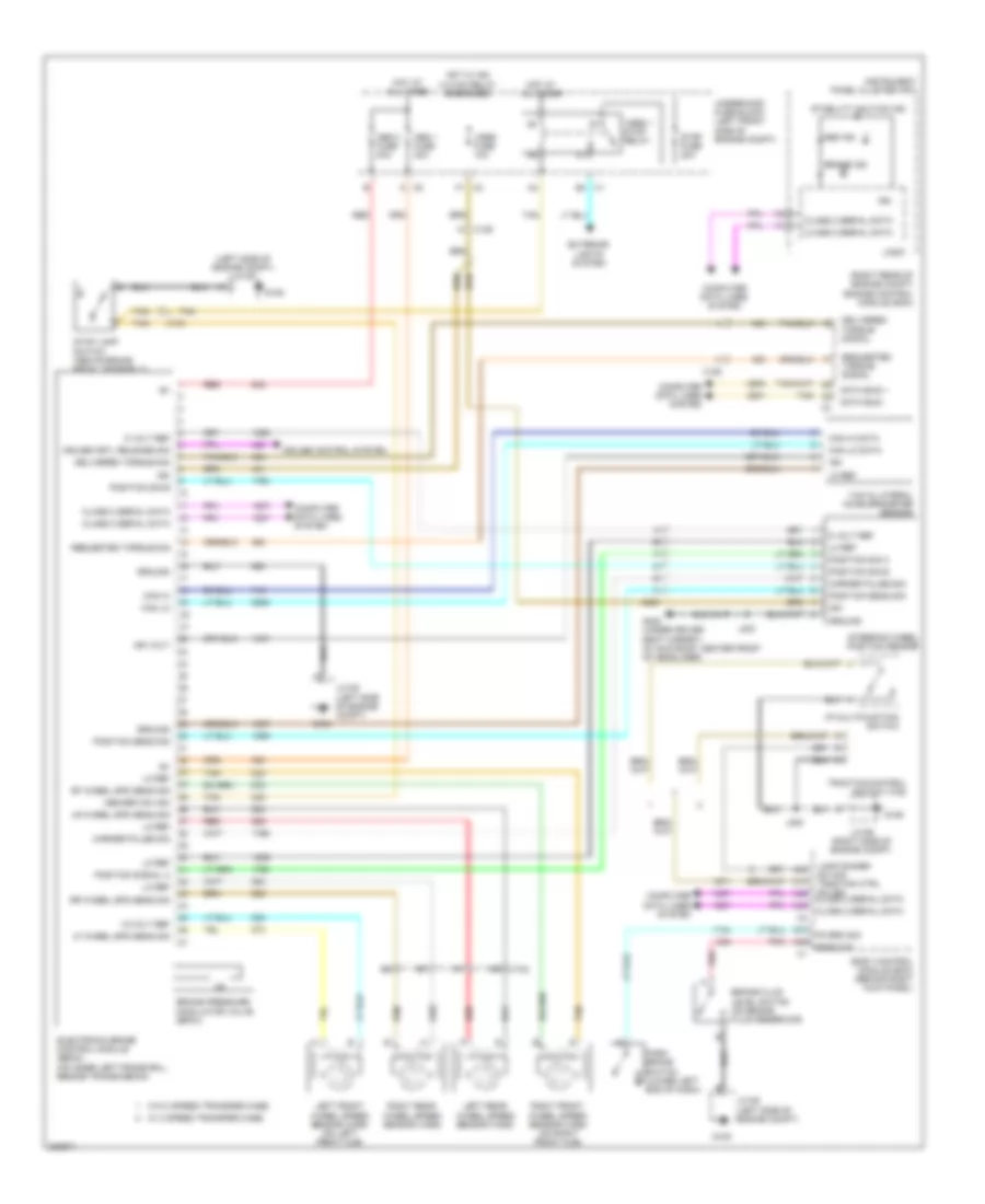
Anti-lock Brakes Wiring Diagram for GMC Canyon 2012
List of elements for Anti-lock Brakes Wiring Diagram for GMC Canyon 2012:
- (left side of engine compt) jx105
- (right rear of engine compt) engine control module (ecm)
- 12-volt ref
- 5 volt ref
- A17
- A31
- A33
- A38
- A44
- A45
- Abs 1 fuse 30a
- Abs 2 fuse 40a
- Abs brk sw sig
- Abs ind
- Body control module (bcm) (behind right kick panel)
- Brake fluid level switch (on brake fluid reservoir)
- Brake ind
- Brake pressure modulator valve (bpmv)
- Can hi
- Can hi data
- Can lo
- Can lo data
- Class 2 serial data
- Computer data lines system
- Cruise control system
- Cruise crtl release sig
- Data bus +
- Data bus -
- Delivered torque sig
- Delivered torque signal
- Electronic brake control module (ebcm) (on inner left frame rail, beside transmission)
- Exterior lights system
- G105
- G106
- G300 (under driver seat carpet) (w/ sun roof: center front of headliner)
- Ground
- Hot at all times
- Hot w/ ign 3 hvac relay energized
- I/p multifunction switch
- Ign
- Ign volt
- Instrument panel cluster (ipc)
- J200
- J303
- Jx105 (left side of engine compt)
- Jx106 (right side of engine compt)
- Lamp dimmer sw sig traction ctrl sw sig class 2 serial data
- Left front wheel speed sensor (wss) (on left front hub)
- Left rear wheel speed sensor (wss)
- Lf wheel spd sens sig
- Lo ref
- Logic
- Lr wheel spd sens sig
- Marker pulse sig
- Park brake switch (lower left end of dash)
- Pk brk sig
- Pnk
- Position sens sig
- Position sig a
- Position sig b
- Position signal a
- Red
- Requested torque sig
- Requested torque signal
- Rf wheel spd sens sig
- Right front wheel speed sensor (wss) (on right front hub)
- Right rear wheel speed sensor (wss)
- Rr wheel spd sens sig
- Sens sig
- Stability caution ind
- Steering wheel position sensor
- Stop fuse 20a
- Stop lamp switch (above brake pedal assembly)
- Tan
- Traction control switch (tcs)
- Underhood fuse block (left front side of engine compt)
- Vses 1 stop relay
- Vses fuse 10a
- W/ 2 speed transfer case
- W/o 2 speed transfer case
- X102
- X104
- X125
- X205
- Yaw & lateral accelerometer sensor
ANTI-THEFT
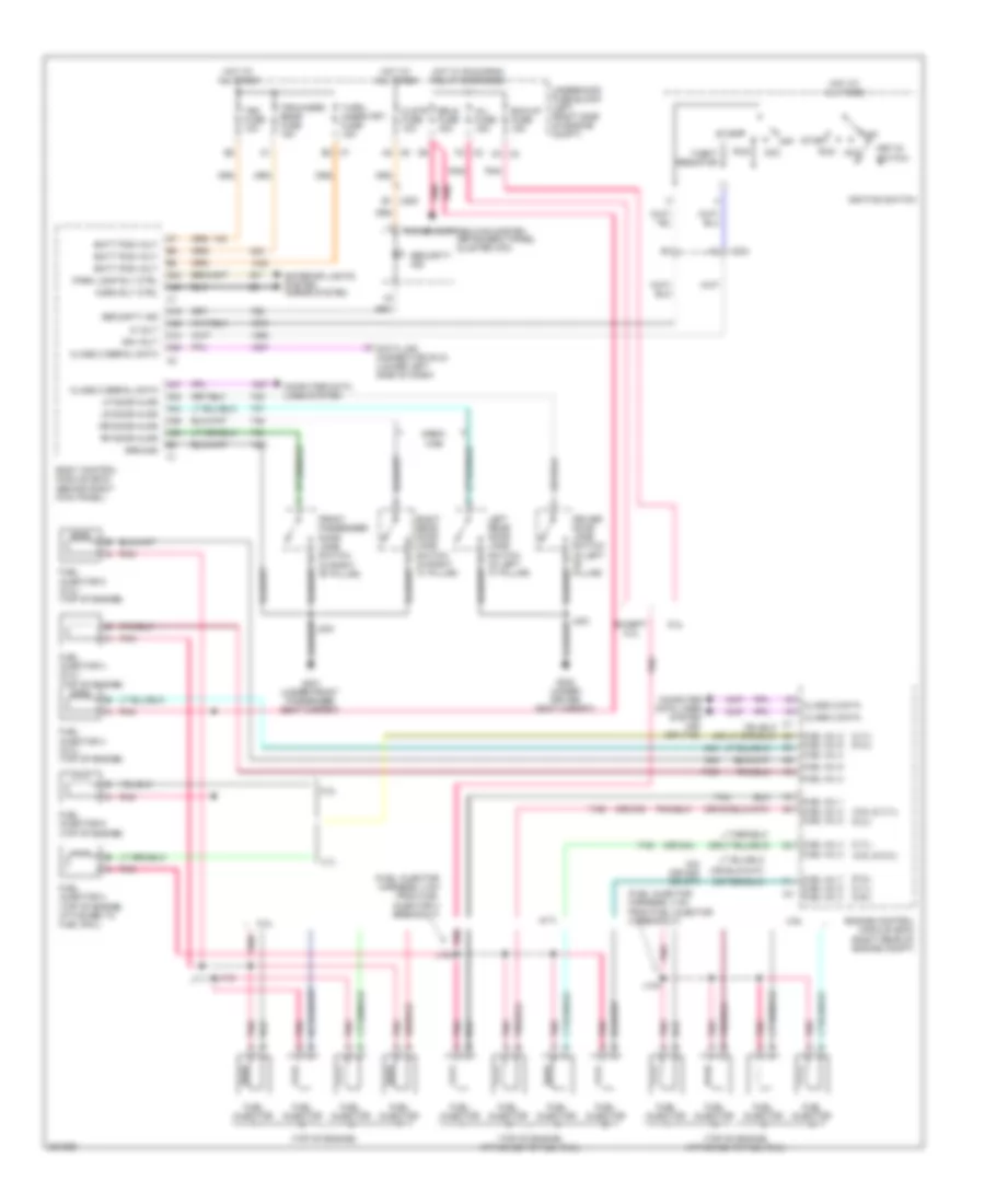
Forced Entry Wiring Diagram for GMC Canyon 2012
List of elements for Forced Entry Wiring Diagram for GMC Canyon 2012:
- (2.9l & 3.7l)
- (2.9l & 5.3l)
- (3.7l)
- (3.7l) (5.3l)
- (5.3l)
- (5.3l) (3.7l) (2.9l)
- (fuel injector harness, 4 cm from fuel injector 4 breakout)
- (or 844)
- (or 845) (or 877)
- (or 878)
- (top of engine)
- (top of engine, attached to fuel rail)
- 2.9l
- 3.7l
- 5 volt
- 5.3l
- A14
- A19
- A2 x6
- A24
- A32
- A38
- A39
- A40
- A42
- A44
- A47
- Acc
- B1 x200
- B3 x7
- Batt pos volt
- Bck/up fuse 15a
- Body control module (bcm) (behind right kick panel)
- Class 2 data
- Class 2 serial data
- Clstr fuse 10a
- Computer data lines system
- Computer data lines system (or 1745)
- Crew cab
- Data link connector (dlc) (lower left side of dash)
- Driver door jamb switch (in left "b" pillar)
- Engine control module (ecm) (right rear of engine compt)
- Erls fuse 15a
- Except 5.3l
- Exterior lights system horns system
- Front passenger door jamb switch (in right "b" pillar)
- Fuel inj 1
- Fuel inj 2 fuel inj 6 fuel inj 4
- Fuel inj 3
- Fuel inj 3 fuel inj 8
- Fuel inj 4 fuel inj 2
- Fuel inj 5
- Fuel inj 7 fuel inj 5 fuel inj 4
- Fuel injector
- Fuel injector 2 (top of engine, attached to fuel rail)
- Fuel injector 3 (5.3l) (top of engine)
- Fuel injector 4 (5.3l) (top of engine)
- Fuel injector 5 (5.3l) (top of engine)
- Fuel injector 6 (top of engine)
- G300 (under driver seat carpet)
- G301 (under front passenger seat carpet)
- Ground
- Horn rly ctrl
- Hot at all times
- Hot w/ run/crnk relay energized
- Ign volt
- Ignition switch
- Inj fuse 15a
- Instrument panel cluster (ipc)
- J104
- J111
- J112
- J304
- Key-in switch
- Left rear door jamb switch (in left "c" pillar)
- Lf door ajar
- Lr door ajar
- Off
- Park lamp rly ctrl
- Pnk
- Pnk j104
- Power distribution system
- Rf door ajar
- Right rear door jamb switch (in right "c" pillar)
- Rr door ajar
- Run
- Security ind
- Start
- Tbc fuse 10a
- Theft resistor
- Trn/hazrd rear fuse 15a
- Turn/ hazrd frt fuse 15a
- Underhood fuse block (left front side of engine compt)
- X2 c3
- X2 f4
- X204
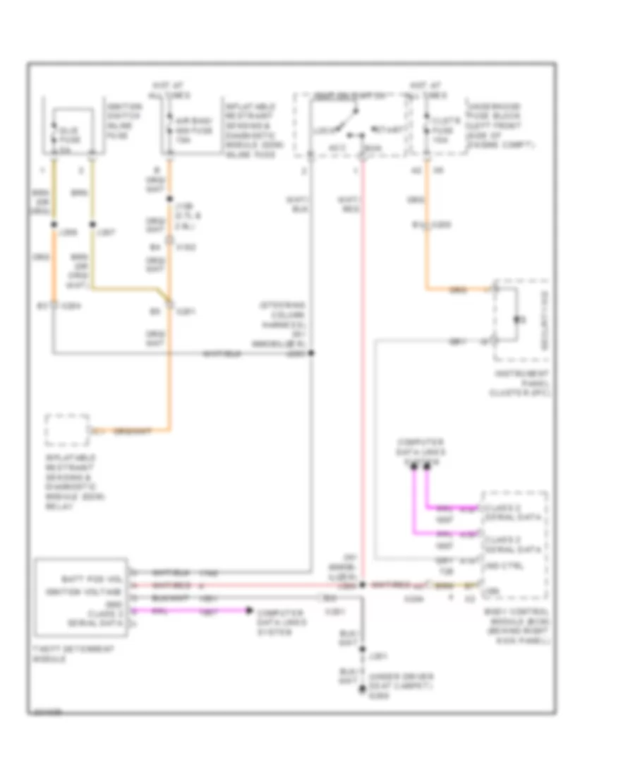
Pass-Key Wiring Diagram for GMC Canyon 2012
List of elements for Pass-Key Wiring Diagram for GMC Canyon 2012:
- (steering column harness) (w/ immobilizer) j203
- (under driver seat carpet) g300
- (w/ immob- ilizer) j204
- 2.9l)
- A19
- A38
- A39
- Acc
- Air bag/ ign fuse 10a
- Batt pos vol
- Body control module (bcm) (behind right kick panel)
- Class 2 serial data
- Clstr fuse 10a
- Computer data lines system
- Dlis fuse 5a
- Gnd class 2 serial data
- Hot at all times
- Ign
- Ignition switch
- Ignition switch inline fuse
- Ignition voltage
- Ind ctrl
- Inflatable restraint sensing & diagnostic module (sdm) inline fuse
- Inflatable restraint sensing & diagnostic module (sdm) relay
- Instrument panel cluster (ipc)
- J106 (3.7l &
- J201
- J207
- J208
- Lock
- Run
- Security ind
- Start
- Theft deterrent module
- Underhood fuse block (left front side of engine compt)
- X102
- X200
- X201
- X204
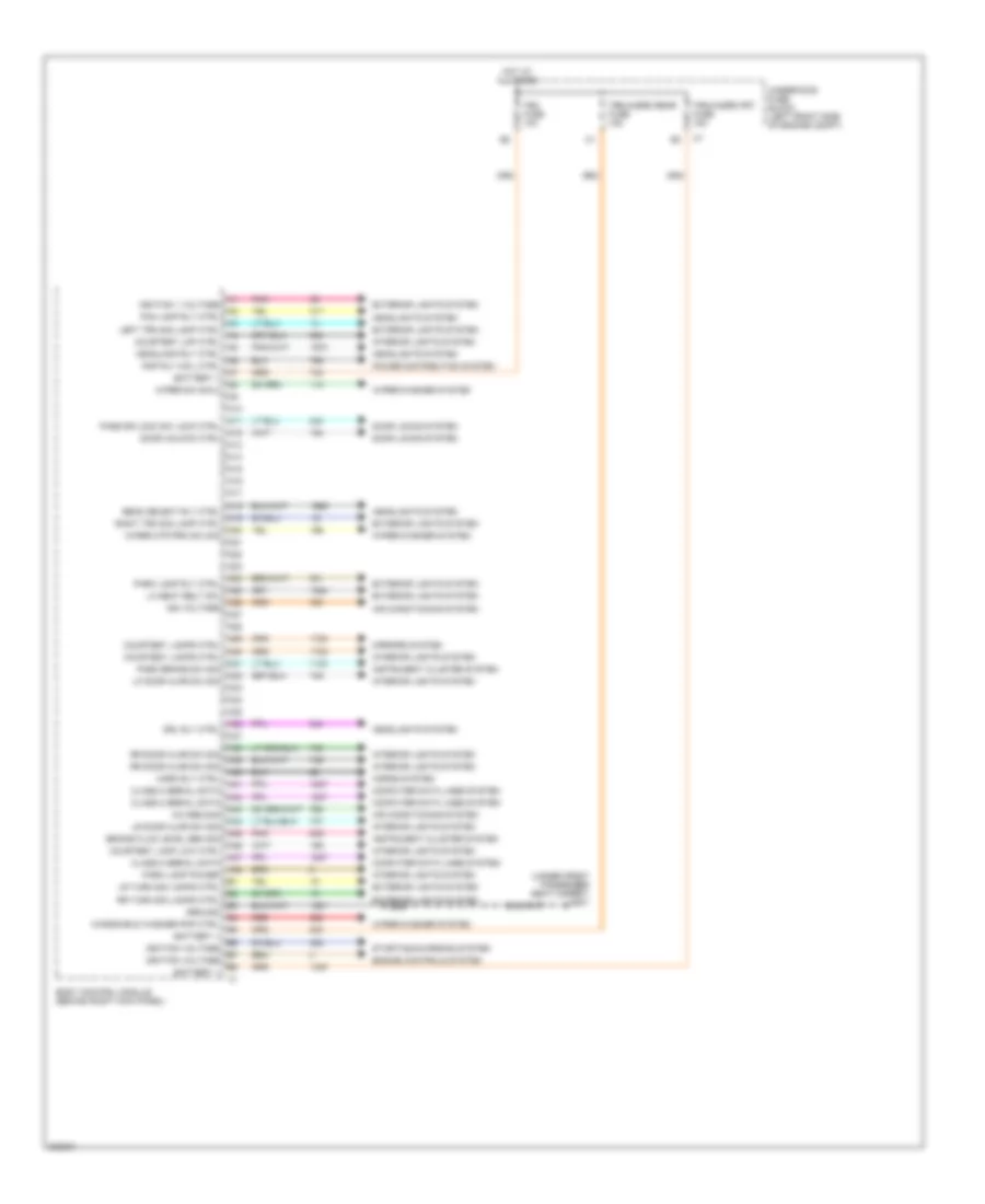
BODY CONTROL MODULES
Body Control Modules Wiring Diagram (1 of 2) for GMC Canyon 2012
List of elements for Body Control Modules Wiring Diagram (1 of 2) for GMC Canyon 2012:
- (under front passenger seat carpet) g301
- A/c req sig
- A10
- A11
- A12
- A13
- A14
- A15
- A16
- A17
- A18
- A19
- A20
- A21
- A22
- A23
- A24
- A25
- A26
- A27
- A28
- A29
- A30
- A31
- A32
- A33
- A34
- A35
- A36
- A37
- A38
- A39
- A40
- A41
- A42
- A43
- A44
- A45
- A46
- A47
- A48
- Air conditioning system
- Battery +
- Beam select rly ctrl
- Body control module (behind right kick panel)
- Brake fluid level sen sig
- Class 2 serial data
- Computer data lines system
- Courtesy lamp low ctrl
- Courtesy lamps ctrl
- Courtesy lmp ctrl
- Door locks system
- Door unlock ctrl
- Drl rly ctrl
- Engine controls system
- Exterior lights system
- Fog lamp rly ctrl
- Ground
- Headlamp rly ctrl
- Headlights system
- Horn rly ctrl
- Horns system
- Hot at all times
- Ign voltage
- Ignition 1 voltage
- Ignition voltage
- Instrument cluster system
- Interior lights system
- J304
- Left trn sig lamp ctrl
- Lf door ajar sw sig
- Lh seat belt sw
- Lr door ajar sw sig
- Lr turn sig lamps ctrl
- Mirrors system
- Park brake sw sig
- Park lamp power
- Park lamp rly ctrl
- Pass dr lock sw lock ctrl
- Pnk
- Power distribution system
- Rap rly coil ctrl
- Red
- Right trn sig lamp ctrl
- Rr door ajar sw sig
- Rr turn sig lamps ctrl
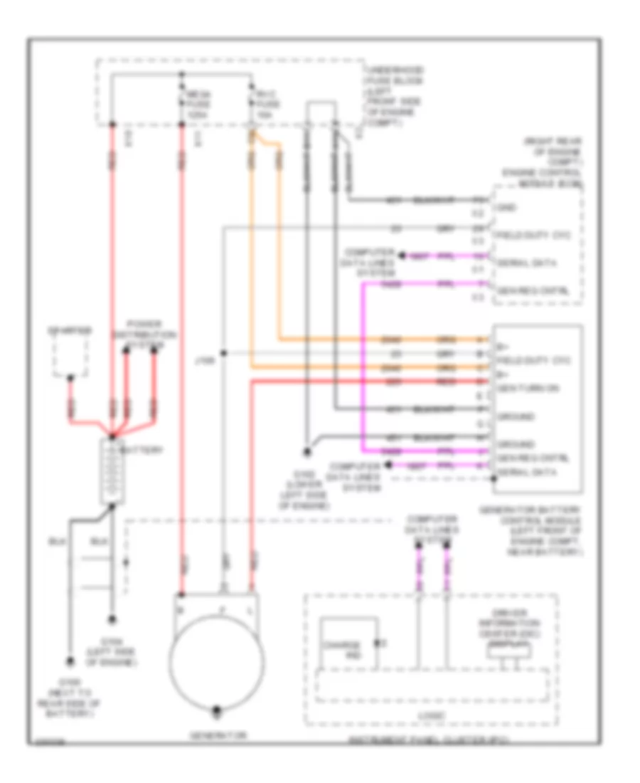
- Starting/charging system
- Tbc fuse 10a
- Trn/hazrd frt fuse 15a
- Trn/hazrd rear fuse 15a
- Underhood fuse block (left front side of engine compt)
- Windshield washer pmp ctrl
- Wiper mtr prk sw sig
- Wiper sw sig 2
- Wiper/washer system
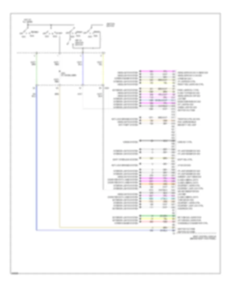
Body Control Modules Wiring Diagram (2 of 2) for GMC Canyon 2012
List of elements for Body Control Modules Wiring Diagram (2 of 2) for GMC Canyon 2012:
- A10
- A11
- A12
- A13
- A14
- A15
- A16
- A17
- A18
- A19
- A20
- A21
- A22
- A23
- A24
- A25
- A26
- A27
- A28
- A29
- A30
- A31
- A32
- A33
- A34
- A35
- A36
- A37
- A38
- A39
- A40
- A41
- A42
- A43
- A44
- A45
- A46
- A47
- A48
- Acc
- Ambient light sens sig
- Anti-lock brakes system
- Anti-theft system
- Body control module (behind right kick panel)
- Cargo lamp sw sig
- Class 2 serial data
- Computer data lines system
- Courtesy lamp low ctrl
- Courtesy lamps ctrl
- Dome over ride sw sig
- Exterior lights system
- Flash to pass sw sig
- Fog lamps enable
- Front fog lamps ind ctrl
- Hazard sw sig
- Headlamps dim sw hi beam sig
- Headlamps sw hi on sig
- Headlamps sw off sig
- Headlights system
- Horn rly ctrl
- Horns system
- Hot at all times
- I/p lamp dimmer sw sig
- I/p lamps dim ctrl
- Ign key resistor sig
- Ignition switch
- Ignition voltage
- Int lamp sw sig
- Interior lights system
- J204 (w/ immobilizer)
- Key in ignition switch
- Low ref
- Lp dim sw sig
- Lr turn sig lamps pwr
- Off
- Park lamps rly ctrl
- Red
- Rr turn sig lamps pwr
- Run
- Security ind lamp
- Shift interlock system
- Shift sol ctrl
- Start
- Traction ctrl sw sig
- Turn sig sw sig
- Windshield washer pmp ctrl
- Wiper sw sig 1
- Wiper/washer system
- X204
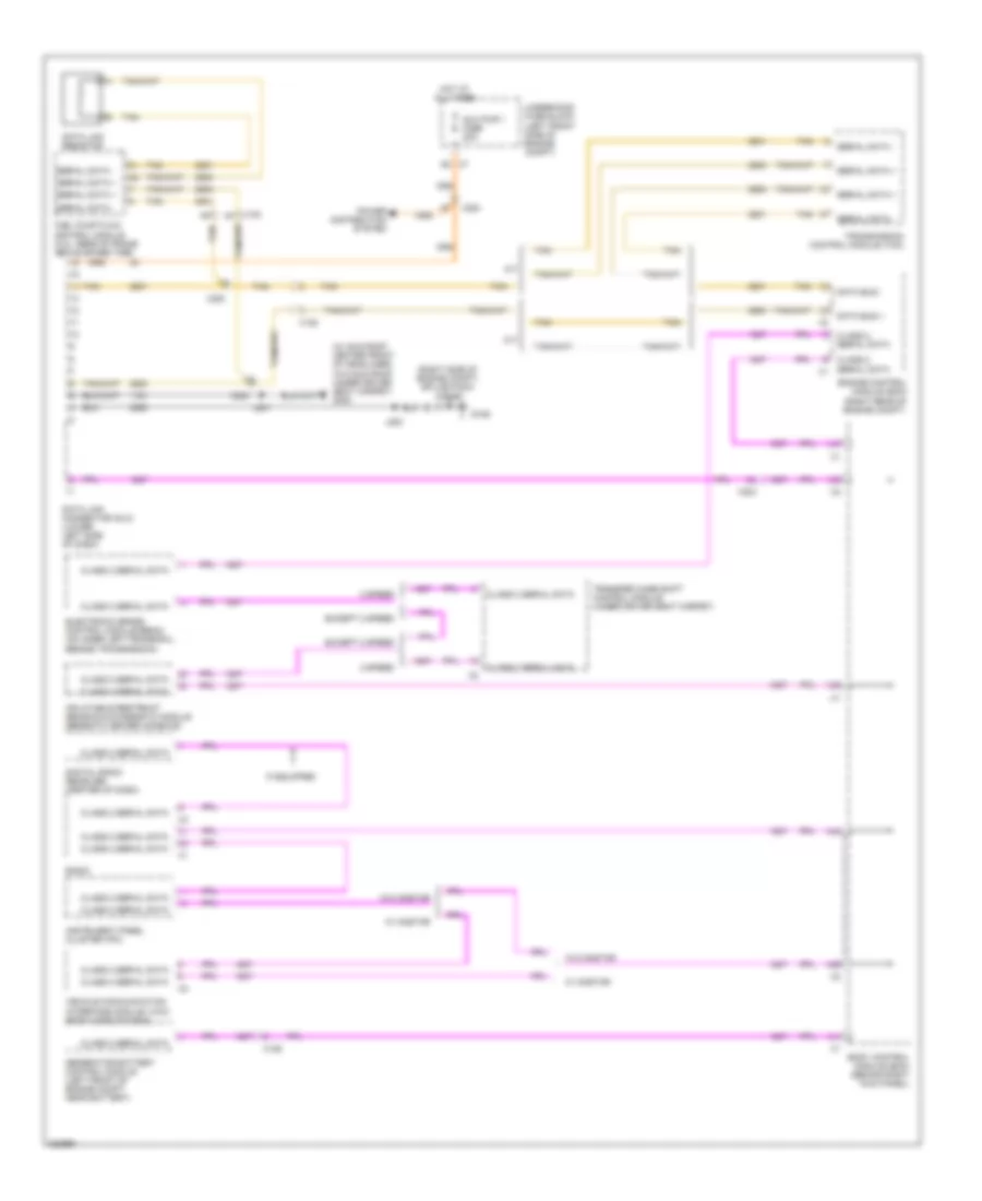
COMPUTER DATA LINES
Computer Data Lines Wiring Diagram for GMC Canyon 2012
List of elements for Computer Data Lines Wiring Diagram for GMC Canyon 2012:
- (right side of engine compt) splice pack jx106
- (w/ sun roof: center front of headliner) (w/o sun roof: under driver seat carpet) g300
- 2 speed
- A/t
- A38
- A39
- A41
- A42
- A44
- A47
- Aux pwr 1 fuse 20a
- Body control module (bcm) (behind right kick panel)
- Class 2 serial data
- Class 2 serial data x1
- Data bus +
- Data bus -
- Data link connector (dlc) (lower left side of dash)
- Data link resistor
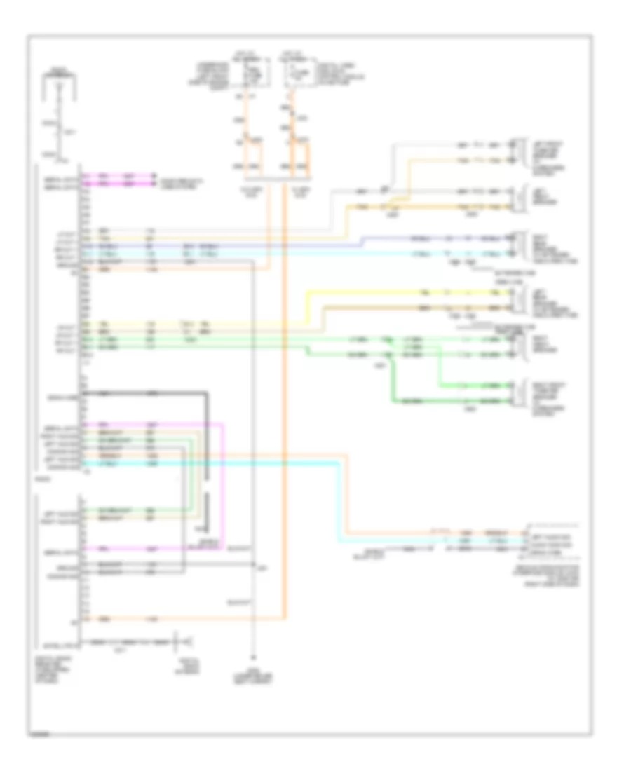
- Digital radio receiver (center of dash)
- Electronic brake control module (ebcm) (on inner left frame rail, beside transmission)
- Engine control module (ecm) (right rear of engine compt)
- Except 2 speed
- Fuel pump flow control module (5.3l: rear of frame above spare tire)
- G106
- Generator battery control module (left front of engine compt, near battery)
- Hot at all times
- If equipped
- Inflatable restraint sensing & diagnostic module (beneath center console)
- Instrument panel cluster (ipc)
- J200
- J201
- M/t
- Power distribution system
- Radio
- Serial data +
- Serial data -
- Tan
- Transfer case shift control module (under driver seat carpet)
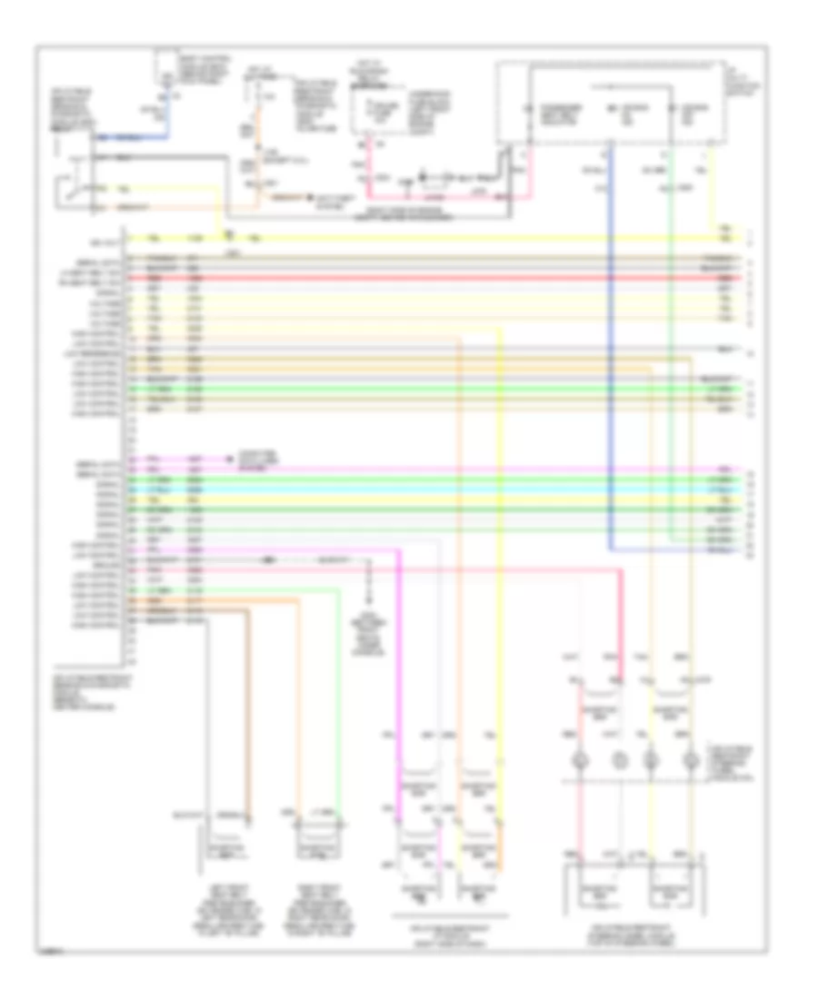
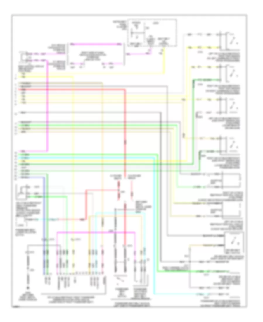
- Transmission control module (tcm)
- Underhood fuse block (left front side of engine compt)
- Vehicle communication interface module (vcim) (right side of dash)
- W/ onstar
- W/o onstar
- X102
- X125
- X200
- X204
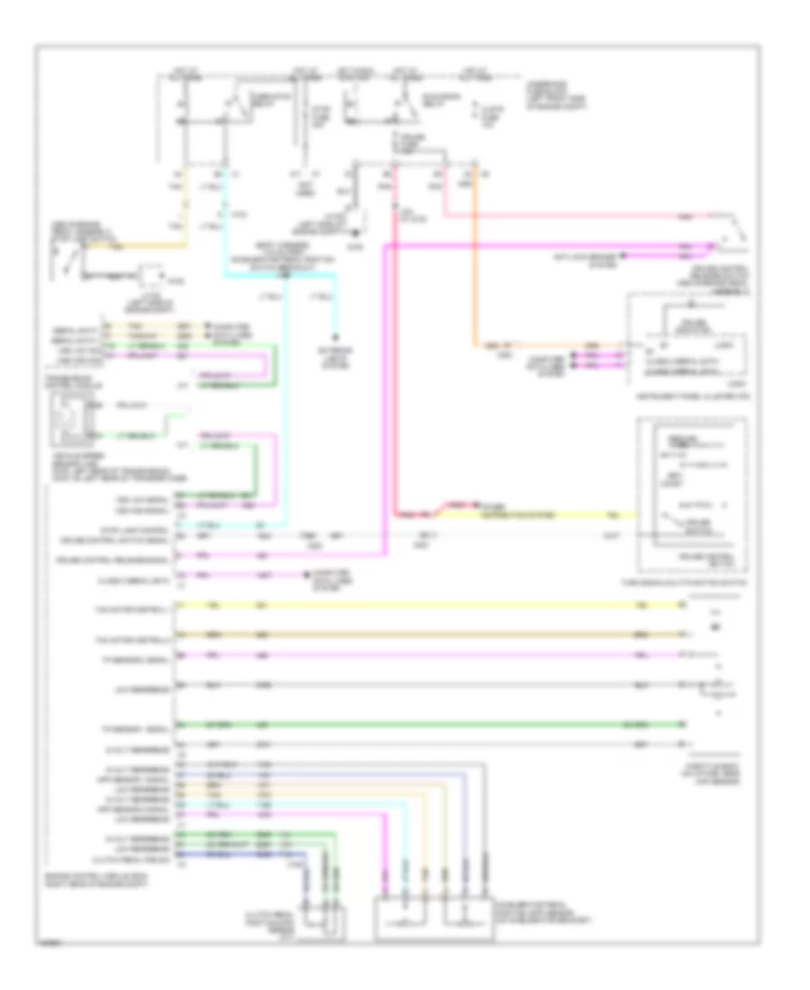
CRUISE CONTROL
Cruise Control Wiring Diagram for GMC Canyon 2012
List of elements for Cruise Control Wiring Diagram for GMC Canyon 2012:
- (above brake pedal assembly) stop lamp switch
- (body harness, 14.5 cm from accelerator pedal position switch breakout) j100
- (not used)
- 5-volt reference
- A/t
- A11
- Accelerator pedal position (app) sensor (on accelerator bracket)
- Anti-lock brakes system
- App sensor 1 signal
- App sensor 2 signal
- Class 2 serial data
- Clstr fuse 10a
- Clutch pedal pos sig
- Clutch pedal position (cpp) sensor (m/t)
- Coast
- Computer data lines system
- Cruise
- Cruise control release signal
- Cruise control release switch (above brake pedal assembly)
- Cruise control switch
- Cruise control switch signal
- Cruise fuse 10a
- Cruise indicator
- Engine control module (ecm) (right rear of engine compt)
- Exterior lights system
- G105
- Hot at all times
- Hot in run or start
- Instrument panel cluster (ipc)
- J331 (w/ dvd)
- Jx105 (left side of engine compt)
- Logic
- Low reference
- M/t
- Pnk
- Power distribution system
- Resume/ accel
- Run/crank relay
- Serial data +
- Serial data -
- Set/
- Stop fuse 20a
- Stop lamp control
- Switch
- Tac motor control-1
- Tac motor control-2
- Tan
- Throttle body (on intake, near map sensor)
- Tp sensor 1 signal
- Tp sensor 2 signal
- Transmission control module
- Turn signal/multi-function switch
- Underhood fuse block (left front side of engine compt)
- Vehicle speed sensor (vss) (2wd: left rear of transmission) (4wd: on left rear of transfer case)
- Vses stop relay
- Vss high sig
- Vss high signal
- Vss low sig
- Vss low signal
- X104
- X125
- X200
- X204
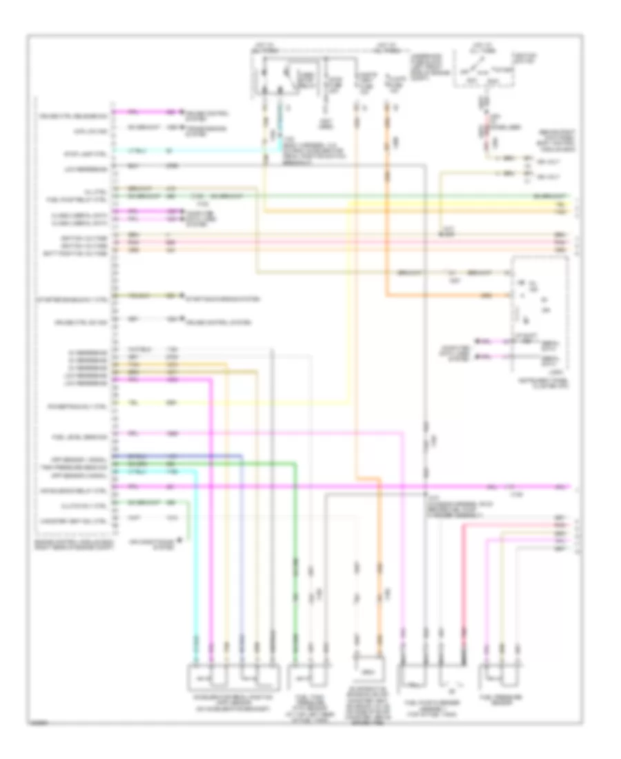
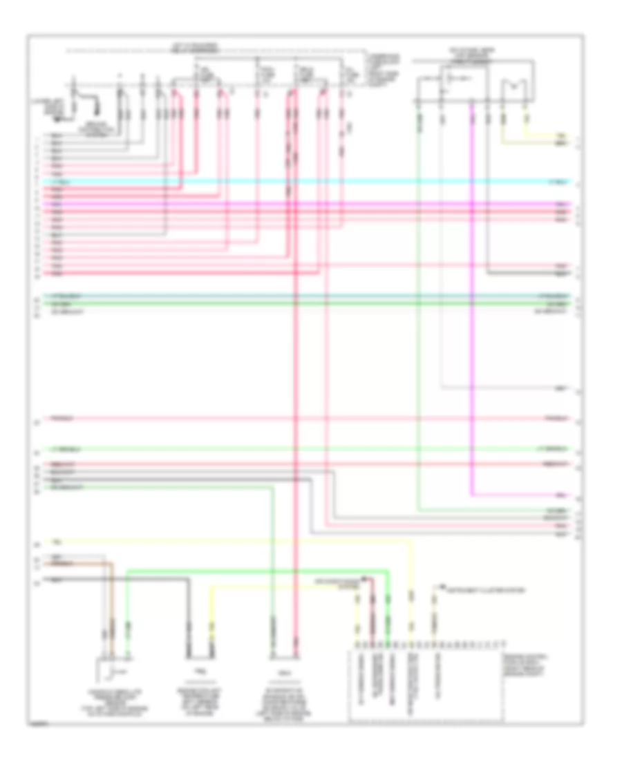
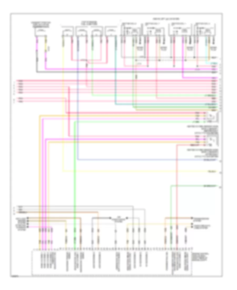
ENGINE PERFORMANCE
2.9L VIN 9
2.9L VIN 9, Engine Performance Wiring Diagram (1 of 5) for GMC Canyon 2012
List of elements for 2.9L VIN 9, Engine Performance Wiring Diagram (1 of 5) for GMC Canyon 2012:
- (a/t) j209
- (behind right kick panel) body control module (bcm)
- (not used)
- 4wd low sig
- 5v reference
- A11
- Acc
- Accelerator pedal position (app) sensor (on accelerator bracket)
- Air conditioning system
- Air solenoid relay ctrl
- App sensor 1 signal
- App sensor 2 signal
- Batt positive voltage
- Canister vent sol ctrl
- Class 2 serial data
- Clstr fuse 10a
- Clutch rly ctrl
- Cnstr vent fuse 10a
- Computer data lines system
- Cruise control system
- Cruise ctrl release sig
- Cruise ctrl sw sig
- Engine control module (ecm) (right rear of engine compt)
- Evaporative emission (evap) canister vent solenoid valve (on side of evap canister, above spare tire)
- Fuel level sens sig
- Fuel pressure sensor
- Fuel pump & sender assembly (top of fuel tank)
- Fuel pump relay ctrl
- Fuel tank pressure (ftp) sensor (at top left rear of fuel tank)
- Hot at all times
- Ign
- Ign volt
- Ignition switch
- Ignition voltage
- Instrument panel cluster (ipc)
- J100 (body harness, 14.5 cm from accelerator pedal position switch breakout)
- J204 (w/ immobilizer)
- J310 (chassis harness, 39 cm before fuel pump & sender assembly)
- Logic
- Low reference
- Mil ctrl
- Mil ind
- Nca
- Off
- Pnk
- Powertrain rly ctrl
- Run
- Serial data
- Start
- Starter enable rly ctrl
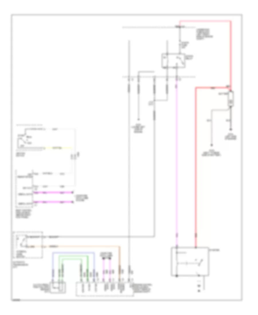
- Starting/charging system
- Stop fuse 20a
- Stop lamp ctrl
- Tan
- Tank pressure sens sig
- Transmissions system
- Underhood fuse block (left front side of engine compt)
- Up shift ind
- Vses/ stop relay
- X102
- X104
- X125
- X200
- X201
- X204
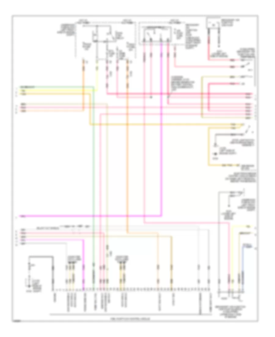
2.9L VIN 9, Engine Performance Wiring Diagram (2 of 5) for GMC Canyon 2012
List of elements for 2.9L VIN 9, Engine Performance Wiring Diagram (2 of 5) for GMC Canyon 2012:
- (if equipped) secondary air injection (air) pump relay
- (in engine harness, 24 cm before generator battery control module breakout) j105
- 5-volt ref
- A red
- Abs brake sw sig
- Air pump fuse 50a
- Air pump relay
- Batt pos volt
- Computer data lines system
- Data bus (+)
- Data bus (-)
- Electronic brake control module (ebcm) (on inner left frame rail, beside transmission)
- Etc fuse 15a
- F11
- Fscm fuse 20a
- Fuel pump flow control module
- G101 (lower left side of engine)
- G103 (lower left side of engine)
- G105
- Ground
- Hot at all times
- Ign volt
- Ignition volt
- J401
- J423
- Jx105 (left side of engine compt)
- Low reference
- Nca
- O2 snsr fuse 15a
- Pcm-b fuse 10a
- Pnk
- Press sens sig
- Pump rel ctrl
- Pump supp volt
- Pwr/ trn relay
- Red
- Secondary air injection (air) pump
- Secondary air injection (air) pump fuse block (if equipped) (right front of engine compt)
- Secondary air injection (air) pump solenoid (if equipped) (upper right side of engine)
- Shield extension
- Stop lamp switch (above brake pedal assembly)
- Tan
- Underhood fuse block (left front side of engine compt)
- X102
- X110
- X125
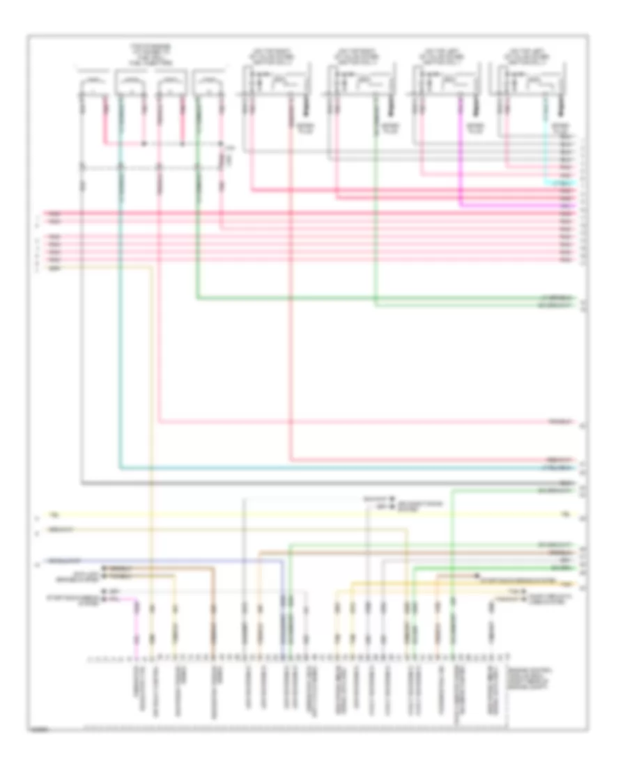
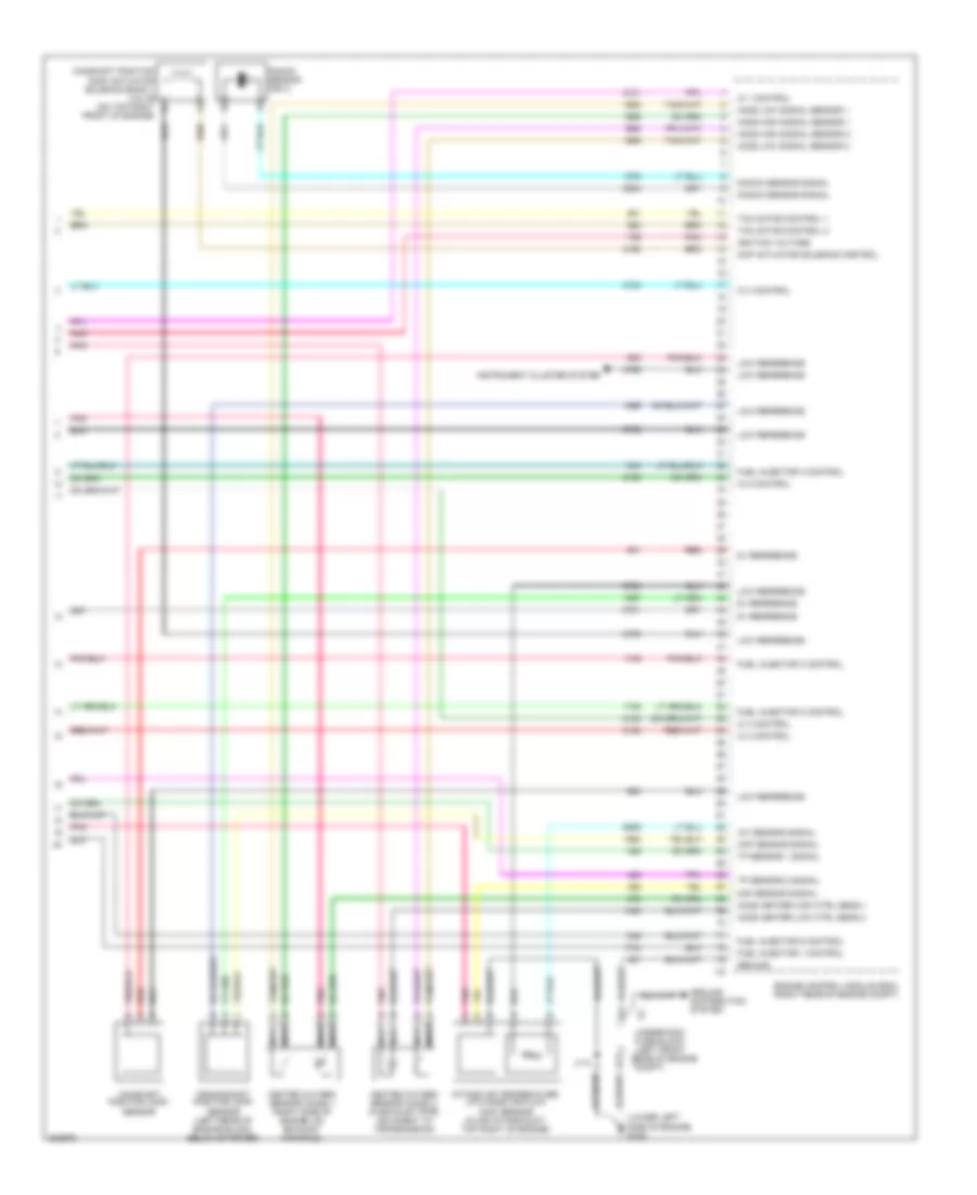
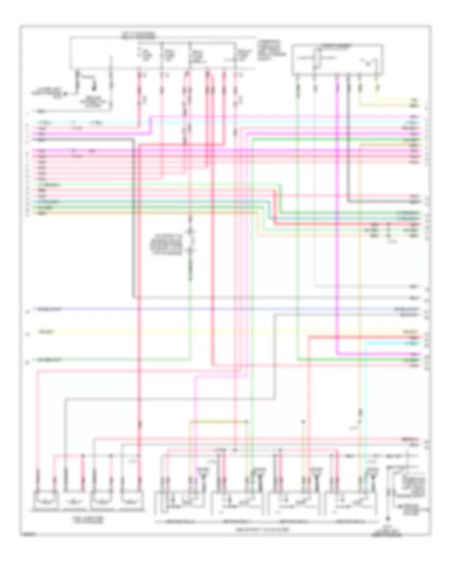
2.9L VIN 9, Engine Performance Wiring Diagram (3 of 5) for GMC Canyon 2012
List of elements for 2.9L VIN 9, Engine Performance Wiring Diagram (3 of 5) for GMC Canyon 2012:
- (on top left of valve cover) ignition coil 1
- (on top left of valve cover) ignition coil 3
- (on top right of valve cover) ignition coil 2
- (on top right of valve cover) ignition coil 4
- (top of engine, attached to fuel rail) fuel injectors
- 5-volt reference
- A pnk
- Air conditioning system
- Air relay control
- Anti-lock brakes system
- Computer data lines system
- Delivered torque
- Duty cycle signal
- Engine control module (ecm) (right rear of engine compt)
- Evap canister purge solenoid control
- Generator
- Generator field
- High speed gmlan
- J104
- Low reference
- Nca
- Park/neutral sig
- Pnk
- Regulator ctrl
- Requested torque signal
- Serial data bus +
- Serial data bus -
- Signal
- Spark plug
- Starting/charging system
- Tan
- X101
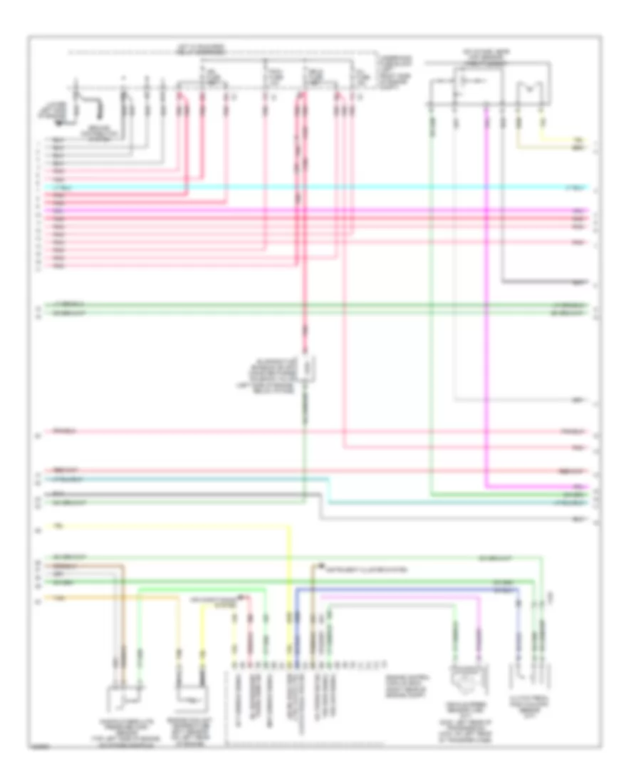
2.9L VIN 9, Engine Performance Wiring Diagram (4 of 5) for GMC Canyon 2012
List of elements for 2.9L VIN 9, Engine Performance Wiring Diagram (4 of 5) for GMC Canyon 2012:
- (lower left side of engine) g103
- (on intake, near map sensor) throttle body
- A/c refrigerant press sens sig
- Air conditioning system
- Air inj reaction
- Clutch pedal pos sig ctrl valve ctrl
- Clutch pedal position (cpp) sensor (m/t)
- D11
- E11
- Ect sensor signal
- Engine control module (ecm) (right rear of engine compt)
- Engine coolant temperature (ect) sensor (on left rear of engine)
- Erls fuse 15a
- Evaporative emission (evap) canister purge solenoid valve (left side of engine, below intake)
- F11
- Ground distribution system
- Hot w/ run/crnk relay energized
- Ign fuse 15a
- Inj fuse 15a
- Instrument cluster system
- Manifold absolute pressure (map) sensor (top left side of engine, on intake manifold)
- Map sensor signal
- Nca
- Oil press sw sig
- Pcm-i fuse 10a
- Pnk
- Tan
- Underhood fuse block (left front side of engine compt)
- Vehicle speed sensor (vss) (m/t) (2wd: left rear of transmission) (4wd: on left rear of transfer case)
- Vss high signal
- Vss low signal
- X102
- X125
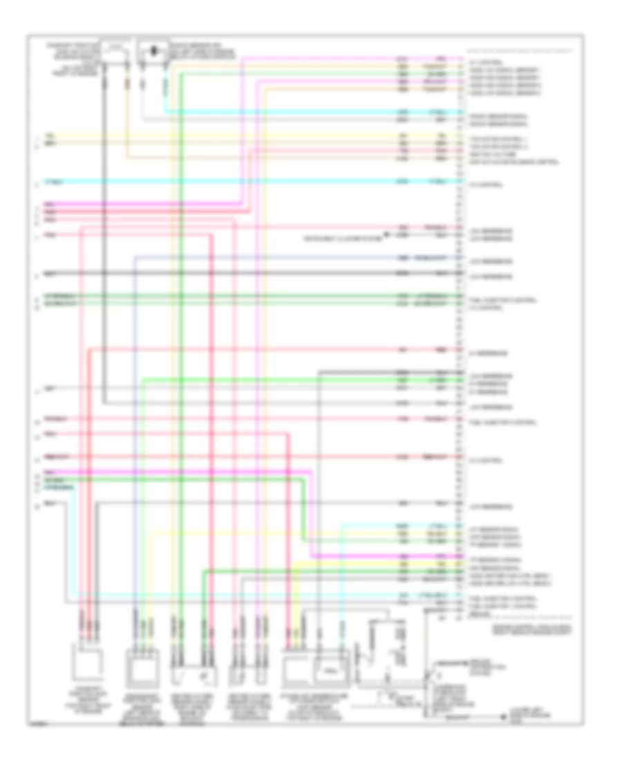
2.9L VIN 9, Engine Performance Wiring Diagram (5 of 5) for GMC Canyon 2012
List of elements for 2.9L VIN 9, Engine Performance Wiring Diagram (5 of 5) for GMC Canyon 2012:
- (lower left side of engine) g102
- 5v reference
- A/t
- A11
- B11
- C11
- Camshaft position (cmp) actuator solenoid bank 1 valve (on top right b
- Camshaft position (cmp) sensor (top right front of engine)
- Ckp sensor signal
- Cmp actuator solenoid control
- Crankshaft position (ckp) sensor (left rear of engine block, below starter)
- Engine control module (ecm) (right rear of engine compt)
- Front of engine)
- Fuel injector 1 control
- Fuel injector 2 control
- Fuel injector 3 control
- Fuel injector 4 control
- Ground
- Ground distribution system
- Heated oxygen sensor (ho2s) 1 (right side of engine, on exhaust manifold)
- Heated oxygen sensor (ho2s) 2 (in exhaust pipe, adjacent to transmission)
- Ho2s heater high ctrl sens 1
- Ho2s heater low ctrl sens 2
- Ho2s high signal sensor 1
- Ho2s high signal sensor 2
- Ho2s low signal sensor 1
- Ho2s low signal sensor 2
- Iat sensor signal
- Ic 1 control
- Ic 2 control
- Ic 3 control
- Ic 4 control
- Ignition voltage
- Instrument cluster system
- Intake air temperature (iat)/mass air flow (maf) sensor (in air intake duct, top right of engine)
- Knock sensor (ks) (on left side of engine, below intake manifold)
- Knock sensor signal
- Low reference
- M/t
- Maf sensor signal
- Nca
- Pnk
- Red
- Start relay 43
- Tac motor control 1
- Tac motor control 2
- Tp sensor 1 signal
- Tp sensor 2 signal
- X2 underhood fuse block (left front side of engine compt) x2
3.7L VIN E
3.7L VIN E, Engine Performance Wiring Diagram (1 of 5) for GMC Canyon 2012
List of elements for 3.7L VIN E, Engine Performance Wiring Diagram (1 of 5) for GMC Canyon 2012:
- (not used)
- 4wd low sig
- 5v ref
- A11
- Abs brake sw sig
- Acc
- Accelerator pedal position (app) sensor (on accelerator bracket)
- Air conditioning system
- Air solenoid relay ctrl
- App sensor 1 sig
- App sensor 2 sig
- Battery positive voltage
- Body control module (bcm) (behind right
- Class 2 serial data
- Cnstr vent fuse 10a
- Compressor clutch rly ctrl
- Computer data lines system
- Cruise control release sig
- Cruise control switch sig
- Cruise control system
- Electronic brake control module (ebcm) (on inner left frame rail, beside transmission)
- Engine control module (ecm) (right rear of engine compt)
- Evap canister vent sol ctrl
- Evaporative emission (evap) canister vent solenoid valve (on side of evap canister, above spare tire)
- Fuel level sensor sig
- Fuel pressure sensor
- Fuel pump & sender assembly (top of fuel tank)
- Fuel pump relay ctrl
- Fuel tank press sensor sig
- Fuel tank pressure (ftp) sensor (at top left rear of fuel tank)
- G105
- Hot at all times
- Ign volt
- Ignition switch
- Ignition voltage
- J100
- J204 (w/ immobilizer)
- J209
- J310 (chassis harness, 39 cm before fuel pump & sender assembly)
- Jx105 (left side of engine compt)
- Kick panel)
- Low ref
- Low reference
- Mil ctrl
- Nca
- Off
- Pnk
- Powertrain relay ctrl
- Run
- Start
- Starter enable relay ctrl
- Starting/charging system
- Stop fuse 20a
- Stop lamp ctrl
- Stop lamp switch (above brake pedal assembly)
- Tan
- Transmissions system
- Underhood fuse block (left front side of engine compt)
- Vses/ stop relay
- X102
- X104
- X125
- X126
- X201
- X204
3.7L VIN E, Engine Performance Wiring Diagram (2 of 5) for GMC Canyon 2012
List of elements for 3.7L VIN E, Engine Performance Wiring Diagram (2 of 5) for GMC Canyon 2012:
- (if equipped) secondary air injection (air) pump relay
- (in engine harness, 24 cm before generator battery control module breakout) j105
- 5-volt ref
- A red
- Air pump fuse 50a
- Air pump relay
- Batt pos volt
- Clstr fuse 10a
- Computer data lines system
- Data bus (+)
- Data bus (-)
- Etc fuse 15a
- F11
- Fscm fuse 20a
- Fuel pump flow control module
- G101 (lower left side of engine)
- G103 (lower left side of engine)
- G105
- Ground
- Hot at all times
- Ign volt
- Ignition volt
- Instrument panel cluster (ipc)
- J401
- J423
- Jx105 (left side of engine compt)
- Logic
- Low reference
- Mil ind
- Nca
- O2 snsr fuse 15a
- Pcm-b fuse 10a
- Pnk
- Press sens sig
- Pump rel ctrl
- Pump supp volt
- Pwr/trn relay
- Red
- Secondary air injection (air) pump (lower right front of engine compt)
- Secondary air injection (air) pump fuse block (if equipped) (right front of engine compt)
- Secondary air injection (air) pump solenoid (if equipped) (upper right side of engine)
- Serial data
- Shield extension
- Tan
- Underhood fuse block (left front side of engine compt)
- X102
- X110
- X125
- X200
3.7L VIN E, Engine Performance Wiring Diagram (3 of 5) for GMC Canyon 2012
List of elements for 3.7L VIN E, Engine Performance Wiring Diagram (3 of 5) for GMC Canyon 2012:
- (on top left of valve cover) ignition coil 1
- (on top left of valve cover) ignition coil 3
- (on top left of valve cover) ignition coil 5
- (on top right of valve cover) ignition coil 2
- (on top right of valve cover) ignition coil 4
- (top of engine, attached to fuel rail) fuel injectors
- 5v reference
- A pnk
- Air conditioning system
- Air relay control
- Anti-lock brakes system
- Computer data lines system
- Delivered torque
- Duty cycle signal
- Engine control module (ecm) (right rear of engine compt)
- Evap canister purge
- Generator
- Generator field
- High speed gmlan
- J104 pnk (fuel injector harness, 4 cm from fuel injector 4 breakout)
- Low reference
- Nca
- Park/neutral sig
- Pnk
- Regulator ctrl
- Requested torque signal
- Serial data bus +
- Serial data bus -
- Signal
- Solenoid control
- Spark plug
- Starting/charging system
- Tan
- X101
3.7L VIN E, Engine Performance Wiring Diagram (4 of 5) for GMC Canyon 2012
List of elements for 3.7L VIN E, Engine Performance Wiring Diagram (4 of 5) for GMC Canyon 2012:
- (lower left side of engine) g103
- (on intake, near map sensor) throttle body
- A/c refrigerant press sens sig
- Air conditioning system
- Air injection reaction ctrl valve ctrl
- D11
- E11
- Ect sensor signal
- Engine control module (ecm) (right rear of engine compt)
- Engine coolant temperature (ect) sensor (on left rear of engine)
- Erls fuse 15a
- Evaporative emission (evap) canister purge solenoid valve (left side of engine, below intake)
- F11
- Ground distribution system
- Hot w/ run/crnk relay energized
- Ign fuse 15a
- Inj fuse 15a
- Instrument cluster system
- Manifold absolute pressure (map) sensor (top left side of engine, on intake manifold)
- Map sensor signal
- Nca
- Oil press sw sig
- Pcm-i fuse 10a
- Pnk
- Underhood fuse block (left front side of engine compt)
- X101
- X102
- X125
3.7L VIN E, Engine Performance Wiring Diagram (5 of 5) for GMC Canyon 2012
List of elements for 3.7L VIN E, Engine Performance Wiring Diagram (5 of 5) for GMC Canyon 2012:
- (lower left side of engine) g102
- 5v reference
- A11
- B11
- Camshaft position (cmp) actuator solenoid bank 1 valve (on top right b
- Camshaft position (cmp) sensor
- Ckp sensor signal
- Cmp actuator solenoid control
- Crankshaft position (ckp) sensor (left rear of engine block, below starter)
- Engine control module (ecm) (right rear of engine compt)
- Front of engine)
- Fuel injector 1 control
- Fuel injector 2 control
- Fuel injector 3 control
- Fuel injector 4 control
- Fuel injector 5 control
- Ground
- Ground distribution system
- Heated oxygen sensor (ho2s) 1 (right side of engine, on exhaust manifold)
- Heated oxygen sensor (ho2s) 2 (in exhaust pipe, adjacent to transmission)
- Ho2s heater high ctrl sens 1
- Ho2s heater low ctrl sens 2
- Ho2s high signal sensor 1
- Ho2s high signal sensor 2
- Ho2s low signal sensor 1
- Ho2s low signal sensor 2
- Iat sensor signal
- Ic 1 control
- Ic 2 control
- Ic 3 control
- Ic 4 control
- Ic 5 control
- Ignition voltage
- Instrument cluster system
- Intake air temperature (iat)/mass air flow (maf) sensor (in air intake duct, top right of engine)
- J110
- Knock sensor (ks) 2
- Knock sensor signal
- Low reference
- Maf sensor signal
- Nca
- Pnk
- Red
- Tac motor control 1
- Tac motor control 2
- Tp sensor 1 signal
- Tp sensor 2 signal
- X2 underhood fuse block (left front x2 side of engine compt)
5.3L VIN P
5.3L VIN P, Engine Performance Wiring Diagram (1 of 5) for GMC Canyon 2012
List of elements for 5.3L VIN P, Engine Performance Wiring Diagram (1 of 5) for GMC Canyon 2012:
- (behind right kick panel) body control module (bcm)
- (not used)
- 4wd low sig
- 5v ref
- A11
- Abs brake sw sig
- Acc
- Accelerator pedal position (app) sensor (on accelerator bracket)
- Air conditioning system
- App sensor 1 signal
- App sensor 2 signal
- Battery positive voltage
- Class 2 serial data
- Cnstr vent fuse 10a
- Compressor clutch rly ctrl
- Computer data lines system
- Cruise control release sig
- Cruise control switch sig
- Cruise control system
- Ect sensor signal
- Electronic brake control module (ebcm) (on inner left frame rail, beside transmission)
- Engine control module (ecm) (right rear of engine compt)
- Engine coolant temperature (ect) sensor (left side of engine)
- Evap canister vent sol ctrl
- Evaporative emission (evap) canister vent solenoid valve (on side of evap canister, above spare tire)
- Fuel level sensor signal
- Fuel pmp rly ctrl
- Fuel pump & sender assembly (top of fuel tank)
- Fuel tank pressure (ftp) sensor (at top left rear of fuel tank)
- Fuel tank pressure sens sig
- G105
- Hot at all times
- Ign volt
- Ignition switch
- Ignition voltage
- J100 (body harness, 14.5 cm from accelerator pedal position switch breakout)
- J204 (w/ immobilizer)
- J207 (4 speed a/t)
- Jx105 (left side of engine compt)
- Low ref
- Map sensor signal
- Mil ctrl
- Nca
- Off
- Pnk
- Powertrain relay control
- Pump & sender assembly) j310
- Refrigerant press sens sig
- Run
- Start
- Starter enable relay ctrl
- Starting/charging system
- Stop fuse 20a
- Stop lamp ctrl
- Stop lamp switch (above brake pedal assembly)
- Tan
- Transmissions system
- Underhood fuse block (left front side of engine compt)
- Vses/ stop relay
- X102
- X104
- X201
- X204
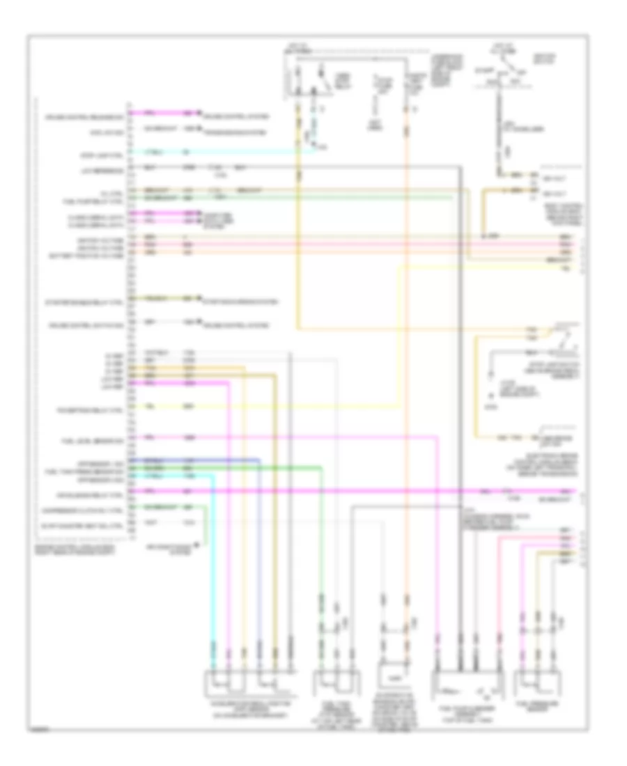
5.3L VIN P, Engine Performance Wiring Diagram (2 of 5) for GMC Canyon 2012
List of elements for 5.3L VIN P, Engine Performance Wiring Diagram (2 of 5) for GMC Canyon 2012:
- 5-volt ref
- Batt pos volt
- Clstr fuse 10a
- Computer data lines system
- Data bus (+)
- Data bus (-)
- Engine oil ind
- Etc fuse 15a
- Fscm fuse 20a
- Fuel pressure sensor
- Fuel pump flow control module (rear of frame above spare tire)
- G105
- Ground
- Hot at all times
- Ign volt
- Ignition volt
- Instrument panel cluster (ipc)
- J106
- J401
- J423
- Jx105 (left side of engine compt)
- Logic
- Low ref
- Manifold absolute pressure (map) sensor (top front of engine)
- Mil ind
- O2 snsr fuse 15a
- Pcm-b fuse 10a
- Pnk
- Press sens sig
- Pump rel ctrl
- Pump supp volt
- Pwr/trn relay 81
- Serial data
- Shld extension
- Tan
- Underhood fuse block (left front side of engine compt)
- X125
- X126
- X200
5.3L VIN P, Engine Performance Wiring Diagram (3 of 5) for GMC Canyon 2012
List of elements for 5.3L VIN P, Engine Performance Wiring Diagram (3 of 5) for GMC Canyon 2012:
- (above left valve cover)
- (top of engine) fuel injectors
- 5v reference
- A pnk
- Air conditioning system
- Anti-lock brakes system
- Bank 2 & sens 1
- Bank 2 & sens 2
- C red
- Camshaft position (cmp) actuator solenoid valve
- Computer data lines system
- D pnk
- Delivered torque
- Duty cycle signal
- Engine control module (ecm) (right rear of engine compt)
- Evap canister purge
- Generator field
- Heated oxygen sensor (ho2s) bank 2 sensor 1 (before right catalytic converter)
- Heated oxygen sensor (ho2s) bank 2 sensor 2 (after right catalytic converter)
- High speed gmlan
- Ho2s heater low
- Ignition coil 1
- Ignition coil 3
- Ignition coil 5
- Ignition coil 7
- J112
- J113
- J114
- J115
- Low reference
- Nca
- Park/neutral sig
- Pnk
- Red
- Regulator ctrl generator
- Requested torque signal
- Serial data bus +
- Serial data bus -
- Signal
- Solenoid control
- Spark plug
- Starting/ charging system
- Tan
- Transmissions system
- X113
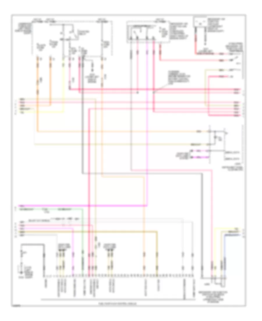
5.3L VIN P, Engine Performance Wiring Diagram (4 of 5) for GMC Canyon 2012
List of elements for 5.3L VIN P, Engine Performance Wiring Diagram (4 of 5) for GMC Canyon 2012:
- (above right valve cover)
- (lower left side of engine) g103
- Bck/up fuse 15a
- C8 pnk
- D11
- E11
- Erls fuse 15a
- Evaporative emission (evap) canister purge solenoid valve (top of engine)
- F11
- Fuel injectors (top of engine)
- G103 (lower left side of engine)
- Ground distribution system
- Hot w/ run/crnk relay energized
- Ign fuse 15a
- Ignition coil 2
- Ignition coil 4
- Ignition coil 6
- Ignition coil 8
- J111
- J116
- J117
- J118
- Nca
- P pnk
- Pcm-i fuse 10a
- Pnk
- Pnk a
- Pnk d
- Red
- Red c
- Spark plug
- Throttle body
- Underhood fuse block (left front side of engine compt)
- X102
- X112
- X115
- X125
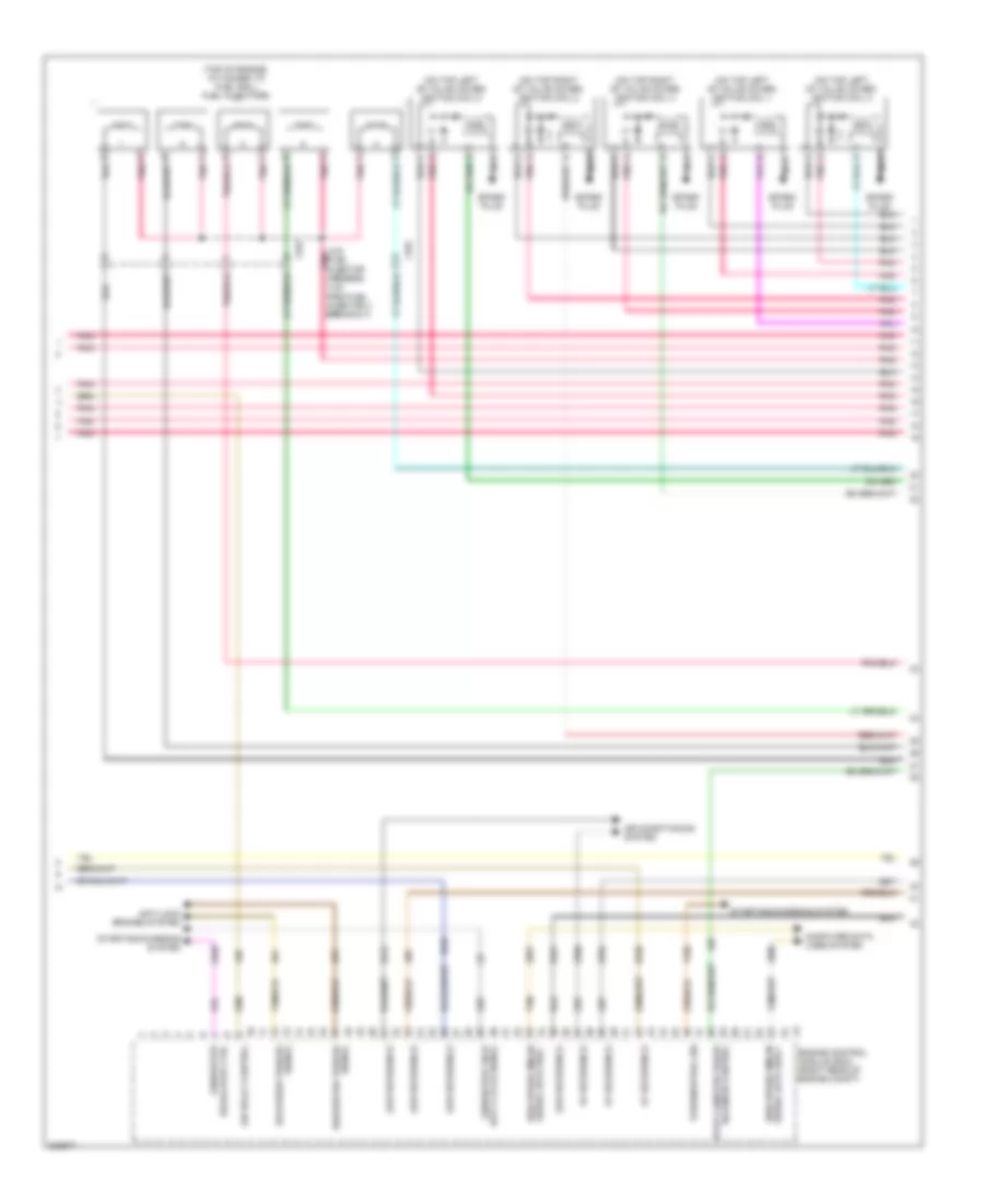
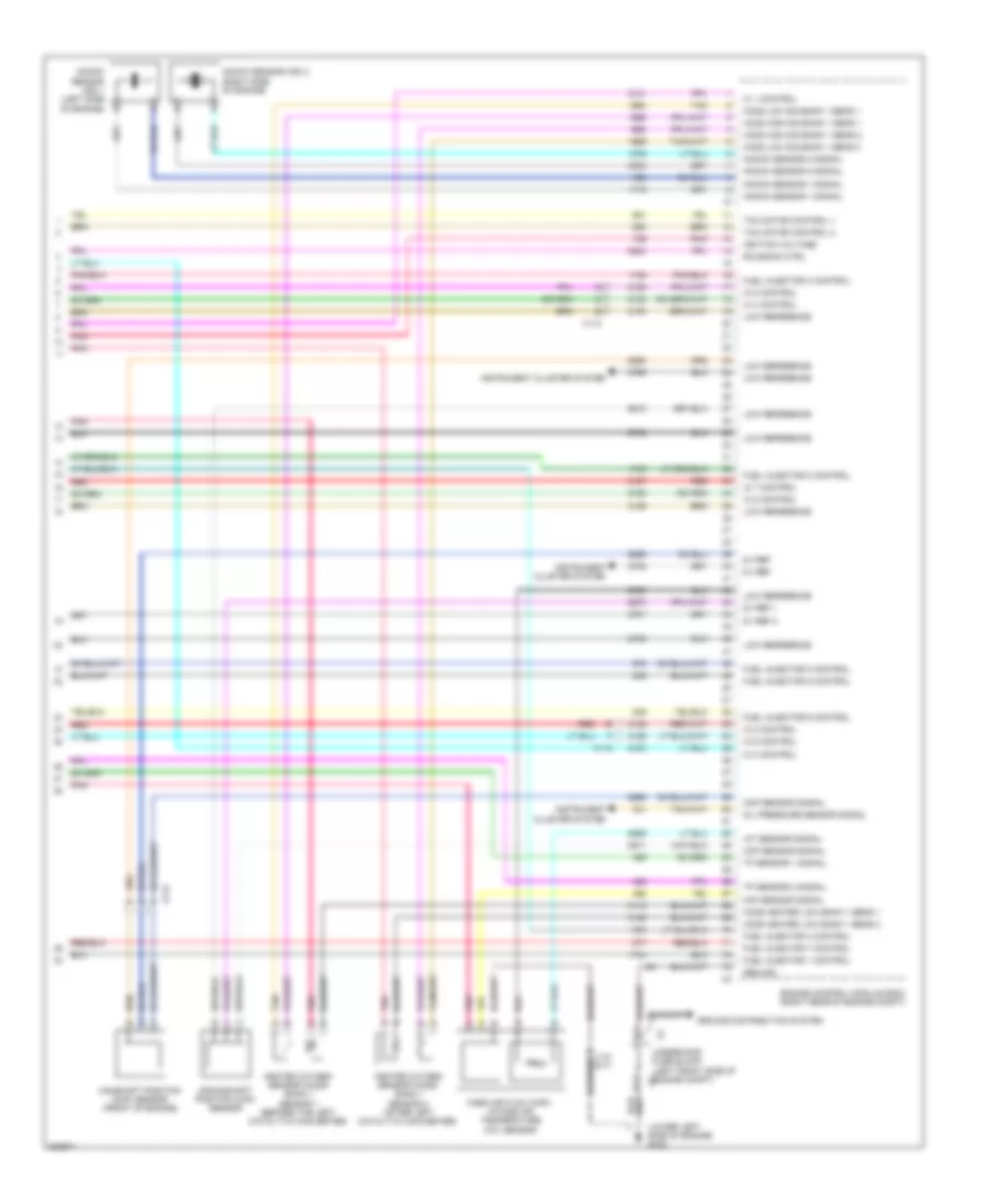
5.3L VIN P, Engine Performance Wiring Diagram (5 of 5) for GMC Canyon 2012
List of elements for 5.3L VIN P, Engine Performance Wiring Diagram (5 of 5) for GMC Canyon 2012:
- (lower left side of engine) g102
- 5v ref
- 5v ref 1
- 5v ref 2
- A11
- B11
- Camshaft position (cmp) sensor (front of engine)
- Ckp sensor signal
- Cmp sensor signal
- Crankshaft position (ckp) sensor
- Engine control module (ecm) (right rear of engine compt)
- Fuel injector 1 control
- Fuel injector 2 control
- Fuel injector 3 control
- Fuel injector 4 control
- Fuel injector 5 control
- Fuel injector 6 control
- Fuel injector 7 control
- Fuel injector 8 control
- Ground
- Ground distribution system
- Heated oxygen sensor (ho2s) bank 1 sensor 1 (before the left catalytic converter)
- Heated oxygen sensor (ho2s) bank 1 sensor 2 (after left catalytic converter)
- Ho2s heater low bank 1 sens 1
- Ho2s heater low bank 1 sens 2
- Ho2s high sig bank 1 sens 1
- Ho2s high sig bank 1 sens 2
- Ho2s low sig bank 1 sens 1
- Ho2s low sig bank 1 sens 2
- Iat sensor signal
- Ic 1 control
- Ic 2 control
- Ic 3 control
- Ic 4 control
- Ic 5 control
- Ic 6 control
- Ic 7 control
- Ic 8 control
- Ignition voltage
- Instrument cluster system
- J110 (a/t)
- Knock sensor (ks) 1 (left side of engine) b
- Knock sensor (ks) 2 (right side of engine)
- Knock sensor 1 signal
- Knock sensor 2 signal
- Low reference
- Maf sensor signal
- Mass air flow (maf)/ intake air temperature (iat) sensor
- Oil pressure sensor signal
- Pnk
- Red
- Solenoid ctrl
- Tac motor control 1
- Tac motor control 2
- Tan
- Tp sensor 1 signal
- Tp sensor 2 signal
- Underhood fuse block (left front side of engine compt) x2
- X112
- X113
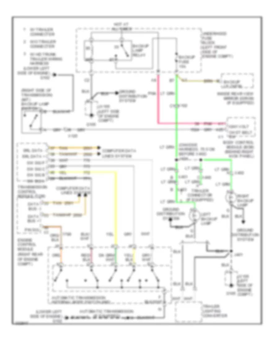
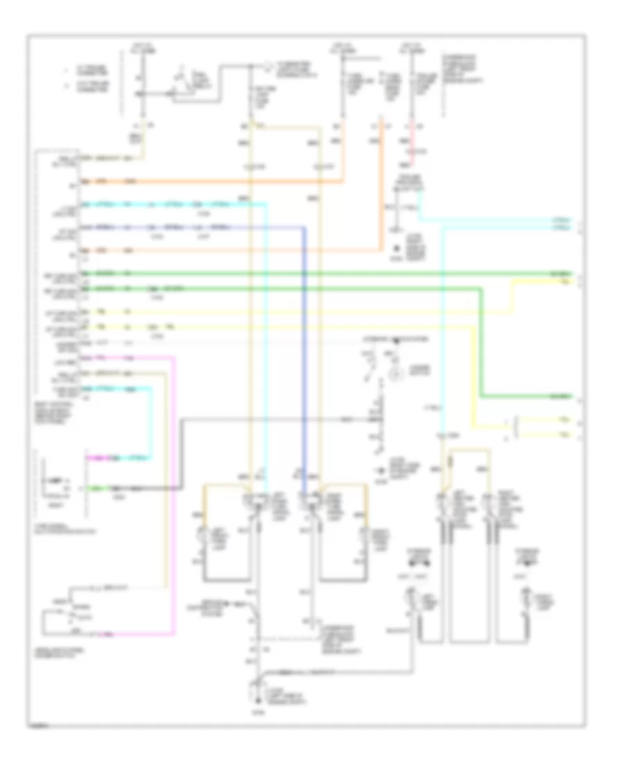
EXTERIOR LIGHTS
Backup Lamps Wiring Diagram for GMC Canyon 2012
List of elements for Backup Lamps Wiring Diagram for GMC Canyon 2012:
- (chassis harness, 75.5 cm before x402) j404
- (left side of engine compt)
- (lower left side of engine) g102
- (right rear
- (right side of transmission) (m/t) backup lamp switch
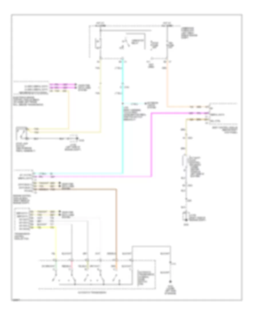
- A25
- Automatic transmission (if equipped)
- Automatic transmission internal mode switch (ims)
- Backup fuse 15a
- Backup lamp relay
- Backup lp cntrl
- Body control module (bcm) (behind right kick panel)
- C x406
- Ch st belt sw
- Computer data
- Computer data lines system
- Data bus +
- Data bus -
- Engine control module
- G105
- Ground distribution system
- Hot at all times
- Ign1 volt
- Inside rear view mirror (isrvm) (if equipped)
- J110
- J401
- Jx105
- Jx105 (left side of engine compt)
- Left backup lamp
- Lines system
- Of engine compt)
- P/n sig
- Pnk
- Right backup lamp
- Srl data +
- Srl data -
- Sw sig a
- Sw sig b
- Sw sig c
- Sw sig p
- Tan
- Trailer connector (if equipped)
- Trailer lighting converter
- Transmission control module (tcm)
- Underhood fuse block (left front side of engine compt)
- W/ hd trunk trailer wiring harness
- W/ trailer connecter
- W/o trailer connecter
- X102 c1
- X125
- X401
- X402
- X403 b
Exterior Lamps Wiring Diagram (1 of 2) for GMC Canyon 2012
List of elements for Exterior Lamps Wiring Diagram (1 of 2) for GMC Canyon 2012:
- A x103
- A x107
- A x108
- A10
- A19
- A24 prk lp rly ctrl
- A45 turn sig sw sig
- A48
- Auto
- Body control module (bcm) (behind right kick panel)
- Frt prk lamp fuse 10a
- G105
- G106
- Ground distribution system
- Hazard sw sig
- Hazard switch
- Head
- Headlamp & panel dimmer switch
- Hot at all times
- Interior lights system
- J200
- Jx105 (left side of engine compt)
- Jx106 (right side of engine compt)
- Left
- Left cargo lamp
- Left front park lamp
- Left park/ turn signal lamp
- Low ref
- Lr turn sig lps ctrl
- Lt sig lps ctrl
- Off
- Park
- Prk lamp relay
- Prk lp rly ctrl
- Red
- Right
- Right cargo lamp
- Right front park lamp
- Right park/ turn signal lamp
- Rr turn sig lps ctrl
- Rt sig lps ctrl
- To rear prk lamp 2 fuse (diagram 2 0f 2)
- Trailer power fuse 30a
- Turn signal/ multi-function switch
- Turn/ hazrd frt fuse 15a
- Turn/ hazrd rear fuse 15a
- Underhood fuse block (left front side of engine compt)
- W/ trailer connecter
- W/o trailer connecter
- X102
- X104
- X107
- X108
- X204
- X320
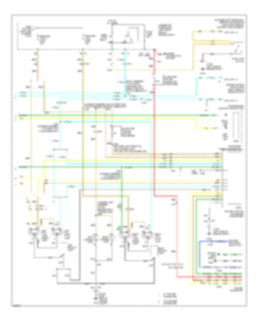
Exterior Lamps Wiring Diagram (2 of 2) for GMC Canyon 2012
List of elements for Exterior Lamps Wiring Diagram (2 of 2) for GMC Canyon 2012:
- (2.9l & 3.7l) b
- (5.3l) g
- (chassis harness, 40.5 cm from fuel pump & sender assembly breakout) j400
- (license lamp harness, 44.5 cm before right license lamp) j900
- (not used)
- (on inner left frame rail, beside transmission)
- 30a
- A/t
- A11
- B x404
- Backup lamps circuit
- Electronic brake control module (ebcm)
- Engine control module (ecm) (right rear of engine compt)
- From frt prk a lamp fuse (diagram 1 0f 2)
- G105
- G400
- Hot at all times
- Inline fuse trailer connector (if equipped)
- Inline fuse trailer lighting converter
- Instrument panel cluster (ipc)
- J107
- J108
- J402 (chassis harness, 13 cm from x401 & x402 breakout)
- J403 (chassis harness, 14 cm from x401 & x402 breakout)
- J901
- Jx105 (left side of engine compt)
- Left backup lamp
- Left license lamp
- Left tail/ stop lamp
- Left tail/ turn signal lamp
- Left turn ind
- Logic
- Power distribution system
- Rear prk lamp 2 fuse 10a
- Rear prk lamp fuse 15a
- Red
- Right backup lamp
- Right license lamp
- Right tail/
- Right tail/ turn signal lamp
- Right turn ind
- Stop fuse 20a
- Stop lamp
- Stop lamp switch
- Stp lmp vlt
- Tan
- Trailer connector
- Trailer lighting converter (if equipped)
- Transmission control module (tcm)
- Underhood fuse block (left front side of engine compt)
- Vses/ stop relay
- W/ trailer connecter
- W/o trailer connecter
- X102
- X104
- X106
- X110
- X125
- X126
- X400
- X401
- X402
- X403
- X405
- X406
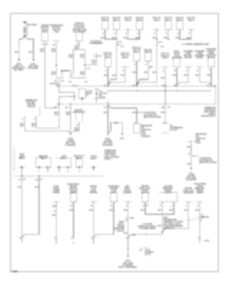
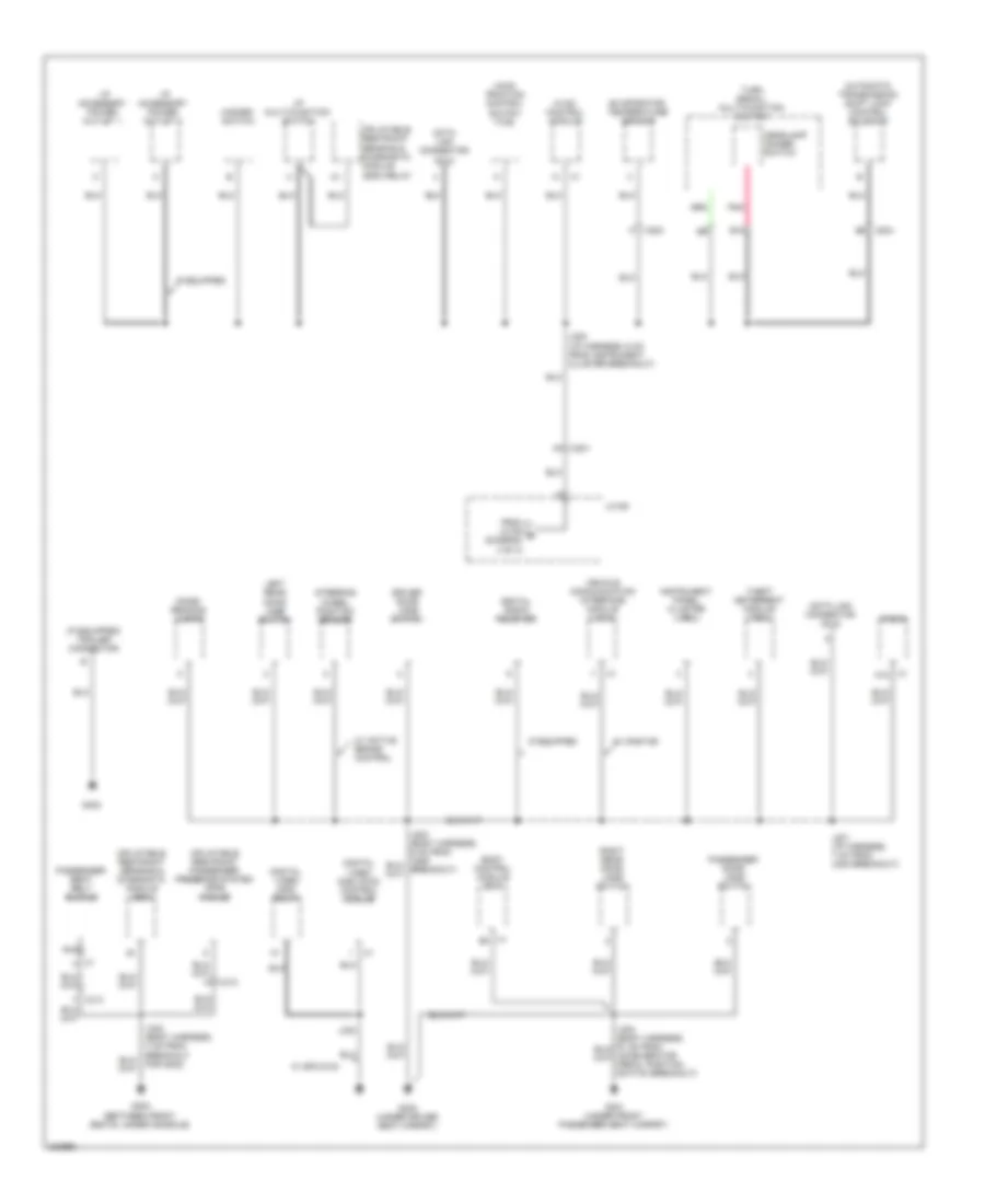
GROUND DISTRIBUTION
Ground Distribution Wiring Diagram (1 of 3) for GMC Canyon 2012
List of elements for Ground Distribution Wiring Diagram (1 of 3) for GMC Canyon 2012:
- (2.9l/3.7l) ignition coil 1
- (2.9l/3.7l) ignition coil 2
- (2.9l/3.7l) ignition coil 3
- (2.9l/3.7l) ignition coil 4
- (if equipped) inside rearview mirror (isrvm)
- 3.7l
- 5.3l
- A/c clutch diode
- A/c compressor clutch
- A/t
- A11
- Automatic transmission
- B11
- Backup lamp switch
- Backup lp relay
- Battery
- Beam sel relay
- Brake fluid level switch
- C11
- Crew cab w/ power operated window
- D11
- Driver door lock actuator
- Driver door lock/ window switch
- E11
- Electronic brake control module (ebcm)
- Engine control module (ecm)
- F11
- Front drive axle actuator
- G100 (next to rear side of battery)
- G101 (lower left side of engine)
- G102 (lower left side of engine)
- G103 (lower left side of engine)
- G104 (left side of engine)
- G105 (left side of engine compt, near ebcm)
- G107
- Generator battery control module
- Ignition coil 1
- Ignition coil 2
- Ignition coil 3
- Ignition coil 4
- Ignition coil 5
- Ignition coil 6
- Ignition coil 7
- Ignition coil 8
- J110
- J115
- J118
- J500 (driver door harness, 5 cm from left front door tweeter speaker breakout)
- Jx105
- Left rear window switch
- M/t
- Mass air flow (maf)/ intake air temperature (iat) sensor
- Nca
- Outside rearview mirror switch
- Run/ crnk relay
- Secondary air injection (air) pump
- Secondary air injection (air) pump solenoid
- Start relay
- To jx105 (diagram 2 of 3)
- Transfer case 2/4 wheel indicator switch
- Transfer case encoder motor
- Transfer case neutral switch
- Transmission control module (tcm)
- Underhood fuse block (left front side of engine compt)
- W/ 2 speed transfer case
- W/ electric air injection reactor system
- W/ onstar
- W/ power operated window outside mirror
- Wind- shield wiper motor
- Windshield washer fluid pump
- Wpr 2 relay
- Wpr relay
- X175 n
- X700
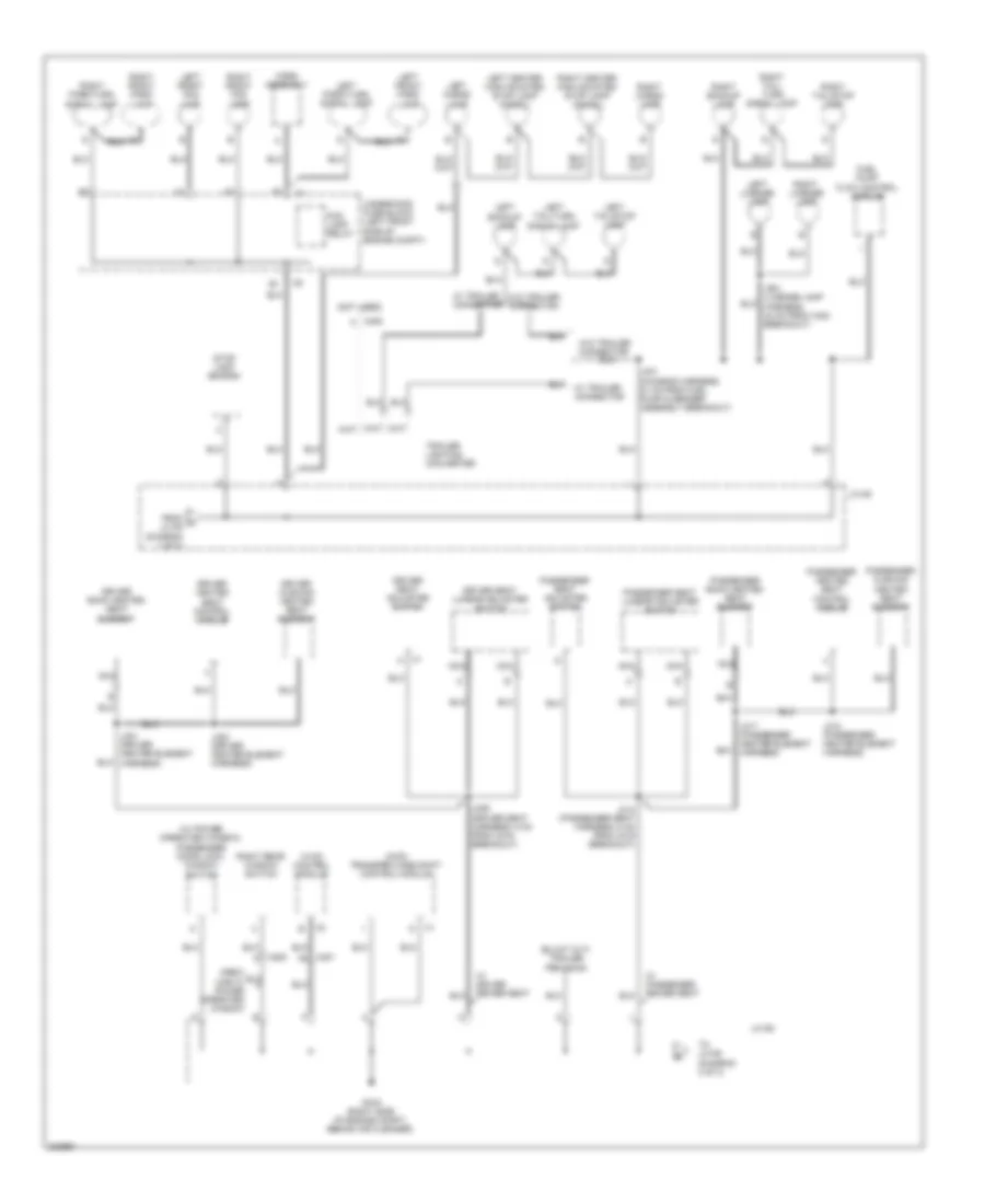
Ground Distribution Wiring Diagram (2 of 3) for GMC Canyon 2012
List of elements for Ground Distribution Wiring Diagram (2 of 3) for GMC Canyon 2012:
- (4wd) transfer case shift control module
- (not used)
- (w/ power operated window) passenger door lock/ window switch
- Crew cab w/ power operated window
- Driver back heated seat element
- Driver cushion heated seat element
- Driver heated seat control module
- Driver seat adjuster switch
- Driver seat lumbar adjuster switch
- Fog lamp relay
- From a jx105 (diagram 1 of 3)
- Fuel pump flow control module
- G106 (right side of engine compt, behind air cleaner)
- Horn assembly
- Hvac control module
- J306 (driver seat harness, 5 cm from x319 breakout)
- J314 (passenger seat harness, 5 cm from x319 breakout)
- J317 (passenger heater element harness)
- J318 (passenger heater element harness)
- J321 (driver heater element harness)
- J322 (driver heater element harness)
- J401 (chassis harness, 21 cm from fuel pump & sender assembly breakout)
- J901 (license lamp harness, 24 cm from x400 breakout)
- Jx105
- Jx106
- Left backup lamp
- Left cargo lamp
- Left center high mounted stop lamp (chmsl)
- Left front fog lamp
- Left front park lamp
- Left license lamp
- Left park/turn signal lamp
- Left tail/stop lamp
- Left tail/turn signal lamp
- Nca
- Passenger back heated seat element
- Passenger cushion heated seat element
- Passenger heated seat control module
- Passenger seat adjuster switch
- Passenger seat lumbar adjuster switch
- Right backup lamp
- Right cargo lamp
- Right center high mounted stop lamp (chmsl)
- Right front fog lamp
- Right front park lamp
- Right license lamp
- Right park/turn signal lamp
- Right rear window switch
- Right tail/ turn signal lamp
- Right tail/stop lamp
- Stop lamp switch
- To jx106 (diagram 3 of 3)
- Trailer lighting converter
- Underhood fuse block (left front side of engine compt)
- W/ driver power seat
- W/ passenger power seat
- W/ trailer connector
- W/o trailer connector
- X1 h
- X201 a5
- X405 a
- X800
Ground Distribution Wiring Diagram (3 of 3) for GMC Canyon 2012
List of elements for Ground Distribution Wiring Diagram (3 of 3) for GMC Canyon 2012:
- (4wd) traction control switch (tcs)
- (between front seats, under console)
- (if equipped) trailer connector
- Automatic transmission shift lock control solenoid
- B10
- B4 x204
- Body control module (bcm)
- Data link connector (dlc)
- Digital radio receiver
- Digital video disc (dvd) control module
- Digital video disc relay
- Dome/ reading lamps
- Driver door jamb switch
- Evaporator temperature sensor
- For g302)
- From jx106 b (diagram 3 of 3)
- G300 (under driver seat carpet)
- G301 (under front passenger seat carpet)
- G302
- G400
- Hazard switch
- Headlamp dimmer switch
- Hvac control module
- I/p accessory power outlet 1
- I/p accessory power outlet 2
- I/p multi-function switch
- If equipped
- Inflatable restraint passenger presence system (pps) module
- Inflatable restraint sensing & diagnostic module (sdm)
- Inflatable restraint sensing & diagnostic module (sdm) relay
- Instrument panel cluster (ipc)
- J200 (i/p harness, 6 cm from instrument cluster breakout)
- J201 (i/p harness, 7 cm from x204 breakout)
- J330
- Jx106
- K x203
- Left rear door jamb switch
- Nca
- Passenger door jamb switch
- Passenger seat belt buckle
- Pnk
- Radio
- Right rear door jamb switch
- Steering wheel position sensor
- Theft deterrent module (tdm)
- Turn signal/ multi-function switch
- Vehicle communication interface module (vcim)
- W/ active brake control
- W/ onstar
- W/ spo dvd
- X1 a
- X1 a12
- X1 b3
- X201 a4
HEADLIGHTS
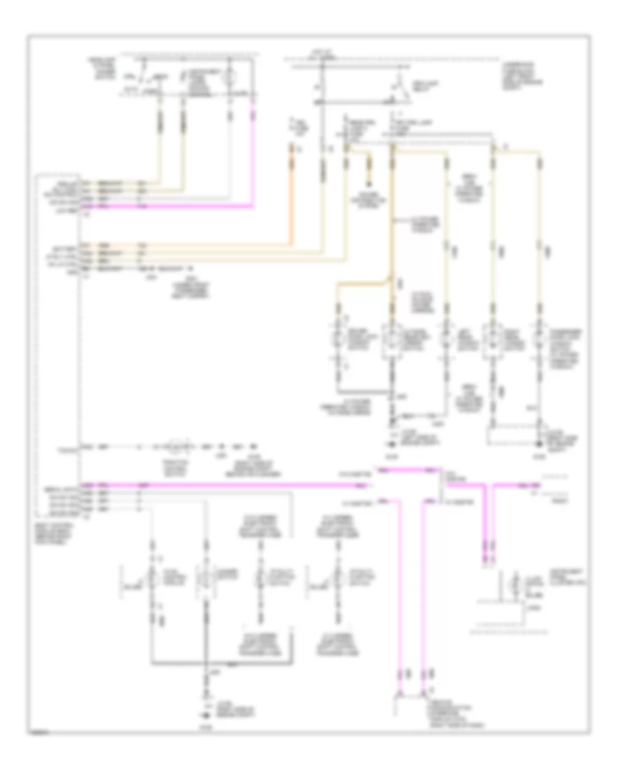
Headlights Wiring Diagram for GMC Canyon 2012
List of elements for Headlights Wiring Diagram for GMC Canyon 2012:
- 87a
- A10
- A11
- A18
- A31
- A36
- A37
- A39
- A43
- Ambient light sensor (upper right side of dash, at windshield)
- Ambient lt sens
- Auto
- B10
- Beam sel relay
- Bm sel rly ctrl
- Body control module (bcm) (behind right kick panel)
- Class 2 data
- Class 2 ser data
- Class 2 serial data
- Computer data lines system
- Drl fuse 10a
- Drl ind
- Drl relay
- Drl relay ctrl
- Flash to pass
- Fog lmp ind
- Fog lp rly ctrl
- Fog lp sw sig
- Fog/ lamp relay
- Fog/lamp fuse 15a
- Front fog lamp ind
- Front fog lamp switch
- G105
- G106
- Ground distribution system
- Hdlp dim sw sig
- Hdlp off sig
- Hdlp on sig
- Hdlp relay
- Hdlp rly ctrl
- Head
- Headlamp & panel dimmer switch
- Headlamp dimmer switch
- High beam
- High beam ind
- Hot at all times
- Ign
- Instrument panel cluster (ipc)
- J200
- Jx105 (left side of engine compt)
- Jx106 (right side of engine compt)
- Left front fog lamp
- Left high beam head- lamp
- Left low beam head- lamp
- Low ref
- Lt hdlp fuse 10a
- Off
- Park
- Park brake switch (lower left end of dash)
- Pk brake sig
- Pnk
- Red
- Right front fog lamp
- Right high beam head- lamp
- Right low beam head- lamp
- Rt hdlp fuse 10a
- Turn signal/ multi-function switch
- Underhood fuse block (left front side of engine compt)
- X1 c2
- X204
- X7 c10
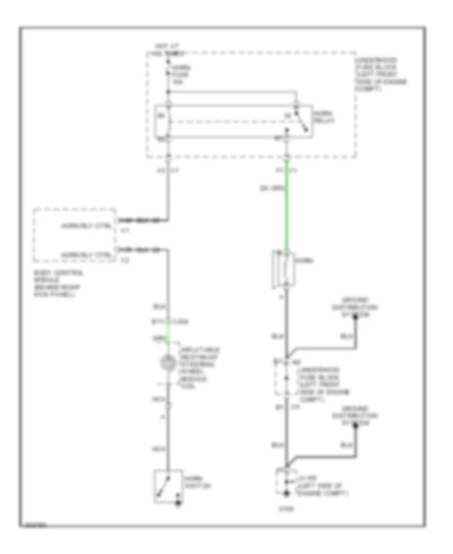
HORN
Horn Wiring Diagram for GMC Canyon 2012
List of elements for Horn Wiring Diagram for GMC Canyon 2012:
- A25
- A40
- A5 x7
- B11
- Body control module (behind right kick panel)
- F1 x1
- G105
- Ground distribution system
- Horn
- Horn fuse 10a
- Horn relay
- Horn rly ctrl
- Horn switch
- Hot at all times
- Inflatable restraint steering wheel module coil
- Jx105 (left side of engine compt)
- Nca
- Underhood fuse block (left front side of engine compt)
- X204
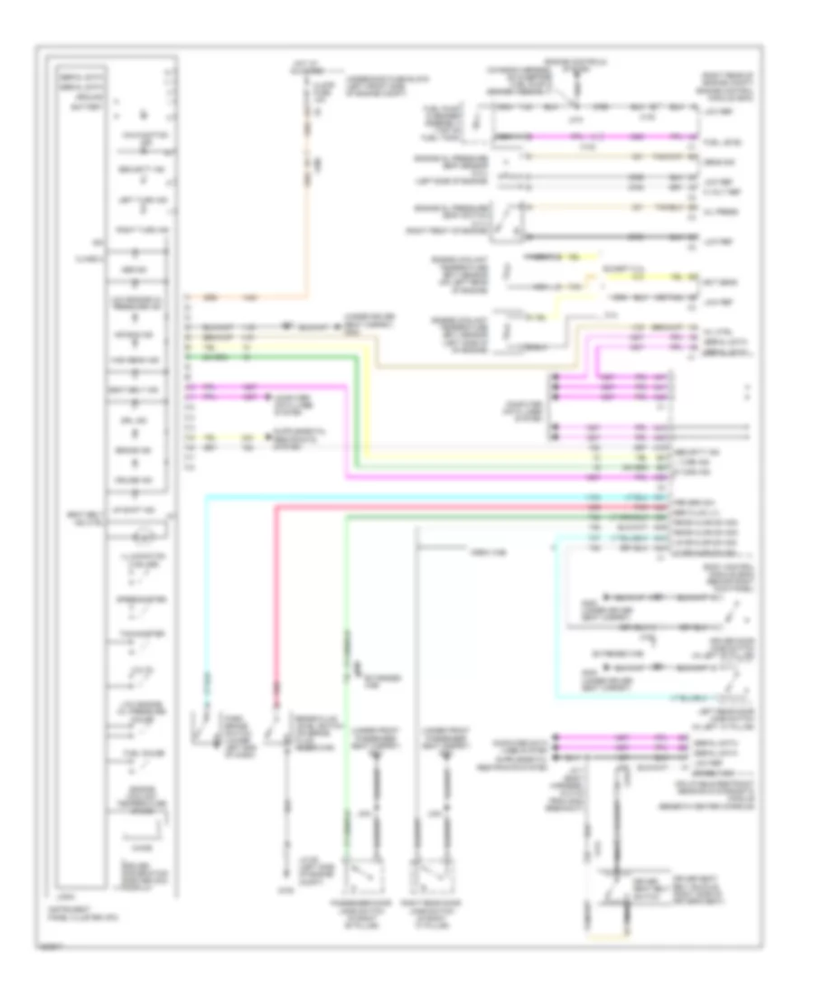
INSTRUMENT CLUSTER
Instrument Cluster Wiring Diagram for GMC Canyon 2012
List of elements for Instrument Cluster Wiring Diagram for GMC Canyon 2012:
- (chassis harness, 39 cm before fuel pump & sender assembly)
- (or tan)
- (right rear of engine compt) engine control module (ecm)
- (under driver seat carpet) g300
- (under front passenger seat carpet) g301
- 5 volt ref
- 5.3l
- A19
- A31
- A32
- A38
- A39
- A41
- A42
- A44
- A45
- A47
- Abs ind
- Air bag ind
- Battery
- Body control module (bcm) (behind right kick panel)
- Brake fluid level switch (on brake fluid reservoir)
- Brake ind
- Brk fluid lvl
- Chime
- Class 2
- Clstr fuse 10a
- Computer data lines system
- Crew cab
- Cruise ind
- Dr belt sw
- Driver door jamb switch (in left "b" pillar)
- Driver information center (dic) display
- Driver seat belt buckle (right side of driver's seat)
- Driver seat belt switch
- Drl ind
- Ect sens
- Engine controls system
- Engine coolant temperature (ect) sensor (left side of of engine)
- Engine coolant temperature (ect) sensor (on left rear of engine)
- Engine coolant temperature gauge
- Engine oil pressure (eop) sensor (5.3l) (left side of engine)
- Engine oil pressure (eop) switch (3.7l) (right front of engine)
- Except 5.3l
- Extended cab
- Fuel gauge
- Fuel level
- Fuel pump & sender assembly (top of fuel tank)
- G105
- G300 (under driver seat carpet)
- Ground
- High beam ind
- Hot at all times
- Ign
- Illumination (4 bulbs)
- Inflatable restraint sensing & diagnostic module (beneath center console)
- Instrument panel cluster (ipc)
- J201
- J303
- J304
- J310
- J311 (body harness, 24.5 cm from g302 breakout)
- Jx105 (left side of engine compt)
- L turn ind
- Left rear door jamb switch (in left "c" pillar)
- Left turn ind
- Lf dr ajar sw sig
- Logic
- Low engine oil pressure gauge
- Low engine oil pressure ind
- Low ref
- Lr dr ajar sw sig
- Malfunction ind
- Mil ctrl
- Nca
- Oil press
- Park brake switch (lower left end of dash)
- Passenger door jamb switch (in right "b" pillar)
- Pnk
- Prk brk sw
- R turn ind
- Right rear door jamb switch (in right "c" pillar)
- Right turn ind
- Rr dr ajar sw sig
- Seat belt ind
- Seat belt ind ctrl
- Security ind
- Sens sig
- Serial data
- Speedometer
- Tachometer
- Tan
- Underhood fuse block (left front side of engine compt)
- Up shift ind
- Volts
- X102
- X200
- X314
- X319
- X700
- X800
INTERIOR LIGHTS
Courtesy Lamps Wiring Diagram for GMC Canyon 2012
List of elements for Courtesy Lamps Wiring Diagram for GMC Canyon 2012:
- (in left "b" pillar)
- (in right "b" pillar)
- A10
- A11
- A12
- A13
- A30
- A32
- A38
- A39
- A44
- A46
- Batt
- Body control module (bcm) (behind right kick panel)
- Cargo lamp switch
- Cargo lp sw
- Courtesy lps
- Crew cab
- Dome on switch
- Dome override switch
- Dome/reading lamps
- Driver door jamb switch
- Extended cab
- G105
- G300 (under driver seat carpet)
- G301 (under front passenger seat carpet)
- Gnd
- Headlamp & panel dimmer switch
- Hot at all times
- J303
- J304
- Jx105 (left side of engine compt)
- Left cargo lamp
- Left center high mounted stop lamp (chmsl)
- Left rear door jamb switch (in left "c" pillar)
- Lf door ajar
- Low ctrl
- Low ref
- Lp sw sig
- Lr door ajar
- Override sw
- Passenger door jamb switch
- Rf door ajar
- Right cargo lamp
- Right center high mounted stop lamp (chmsl)
- Right rear door jamb switch (in right "c" pillar)
- Rr door ajar
- Tbc fuse 10a
- Trn/hazrd frt fuse 15a
- Underhood fuse block (left front side of engine compt)
- W/ premium lighting
- X310
- X320
- X700
- X800
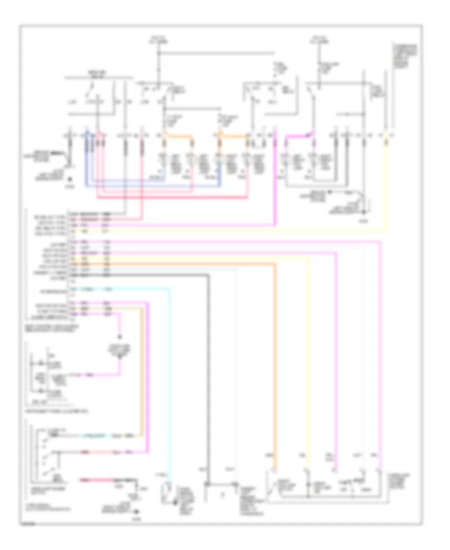
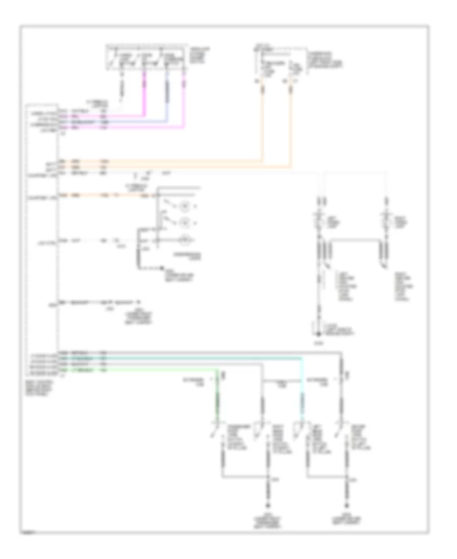
Instrument Illumination Wiring Diagram for GMC Canyon 2012
List of elements for Instrument Illumination Wiring Diagram for GMC Canyon 2012:
- (3 bulbs)
- A10
- A24
- A28
- A29
- A33
- A35
- A36
- A39
- A48
- A7 prklmp rly ctrl a4
- Auto
- Battery
- Body control module (bcm) (behind right kick panel)
- C11
- Crew cab w/ power operated window
- Dim control
- Dim sw sig
- Driver door lock/ window switch
- F11
- Frt prk lamp fuse 10a
- G105
- G106
- G106 (right side of engine compt, behind air cleaner)
- G301 (under front passenger seat carpet)
- Gnd
- Hazard switch
- Head
- Headlamp & panel dimmer switch
- Hot at all times
- Hvac control module
- I/p multi- function switch
- Illum
- Illumi- nation (4 bulbs)
- Instrument panel cluster (ipc)
- Instrument panel lamps dimming control
- J200
- J304
- J500
- Jx105 (left side of engine compt)
- Jx106 (right side of engine compt)
- Left rear window switch
- Logic
- Low ref
- Lp rly ctrl
- Off
- Outside rearview mirror switch
- Park
- Passenger door lock/ window switch (w/ power operated window)
- Pk lp ctrl
- Power distribution system
- Prk/lamp relay
- Radio
- Rear prk lamp 2 fuse 10a
- Right rear window switch
- Serial data
- Tbc fuse 10a
- Tcs sw
- Traction control switch
- Underhood fuse block (left front side of engine compt)
- W/ 2 speed electronic shift control transfer case
- W/ dual folding power mirrors
- W/ onstar
- W/ power operated window
- W/ power operated window outside mirror
- W/o 2 speed electronic shift control transfer case
- W/o onstar
- X2 vehicle communication interface module (vcim) (right side of dash)
- X501
- X600
- X700
- X800
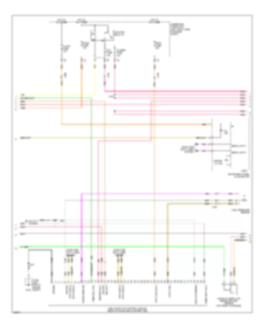
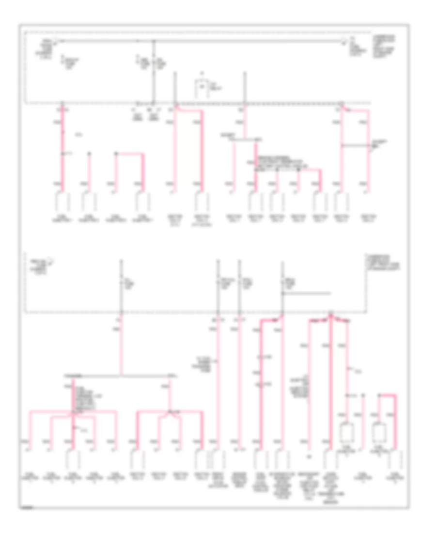
POWER DISTRIBUTION
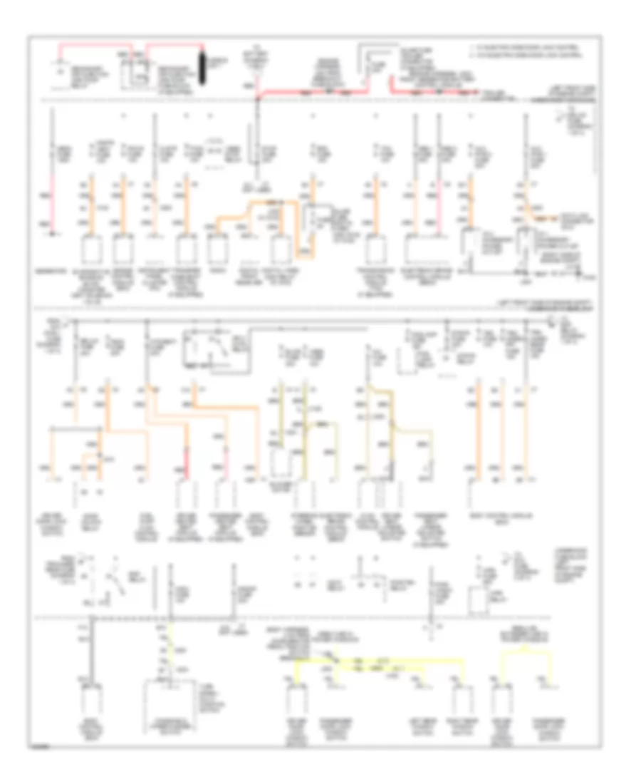
Power Distribution Wiring Diagram (1 of 4) for GMC Canyon 2012
List of elements for Power Distribution Wiring Diagram (1 of 4) for GMC Canyon 2012:
- (body harness, 4 cm from accelerator pedal position switch breakout)
- (engine harness, 18cm front generator battery control module) j107
- (engine harness, 3cm from breakout fuse block) j108
- (if equipped)
- (left front side of engine compt) underhood fuse block
- (not used)
- (right side of engine compt) jx106
- 50a
- A/c fuse 10a
- A10
- A11
- A26
- Abs 1 fuse 30a
- Abs 2 fuse 40a
- Aux pwr 1 fuse 20a
- Aux pwr 2 fuse 20a
- B10
- B11
- Battery (diagram 2 of 4)
- Blower motor
- Blwr fuse 30a
- Body control module (bcm)
- Clstr fuse 10a
- Cnstr vent fuse 10a
- Crew cab w/ power windows
- Data link connector (dlc)
- Digital radio receiver
- Digital video disc relay (w/ dvd)
- Door unlock relay
- Dr/lck fuse 20a
- Driver door lock/ window switch
- Driver heated seat module
- Driver seat lumbar adjuster switch
- E red
- Electronic brake control module (ebcm)
- Engine control module (ecm)
- Evaporative emission (evap) canister vent solenoid valve
- F10
- F12
- Fog/ lamp relay
- Fog/lamp fuse 15a
- From a aux pwr 1 fuse (diagram 1 of 4)
- From b trn/hazrd rear fuse (diagram 1 of 4)
- Fscm fuse 20a
- Fuel pump flow control module
- Fuse 30a
- Fuse 5a
- Fusible link 1
- G106
- Generator
- Hdlp relay
- Htd/seat fuse 20a
- Hvac control module
- I/p 1 accessory power outlet
- I/p 2 accessory power outlet
- Ign 3 hvac relay
- Inline fuse digital video disc (dvd) (w/ dvd)
- Inline fuse trailer connector (if equipped)
- Instrument panel cluster (ipc)
- J200
- J302
- J332 (w/ dvd)
- J510
- Left rear window switch
- Mega fuse 125a
- Nca
- Passenger door lock/ window switch
- Passenger heated seat module
- Passenger seat lumbar adjuster switch (if equipped)
- Pcm b fuse 10a
- Pwr/ wndw fuse 30a
- Pwr/trn relay
- Radio
- Rap relay
- Rdo fuse 15a
- Red
- Regular, extended cab w/ power windows
- Right rear window switch
- S/roof fuse 20a
- Secondary air injection (air) pump fuse block (if equipped)
- Secondary air injection (air) pump relay
- Steering wheel position sensor
- Stop fuse 20a
- Strtr fuse 30a
- Strtr relay
- Tbc fuse 10a
- Tccm fuse 10a
- Tcm fuse 10a
- To dr/lck fuse (diagram 1 of 4)
- To rap relay (diagram 1 of 4)
- To rvc fuse (diagram 2 of 4)
- Trailer connector
- Transfer case shift control module (if equipped)
- Transmission control module (tcm) (if equipped)
- Trn/ hazrd frt fuse 15a
- Trn/ hazrd rear fuse 15a
- Turn signal/ multi- function switch
- Underhood fuse block (left front side of engine compt)
- Vses fuse 10a
- Vses/ stop relay
- W/ electric side door lock control
- W/o electric side door lock control
- Windshield wiper/washer switch
- Wpr fuse 25a
- Wpr relay
- Wsw fuse 10a
- X102
- X125
- X200
- X201
- X204
- X700
- X800
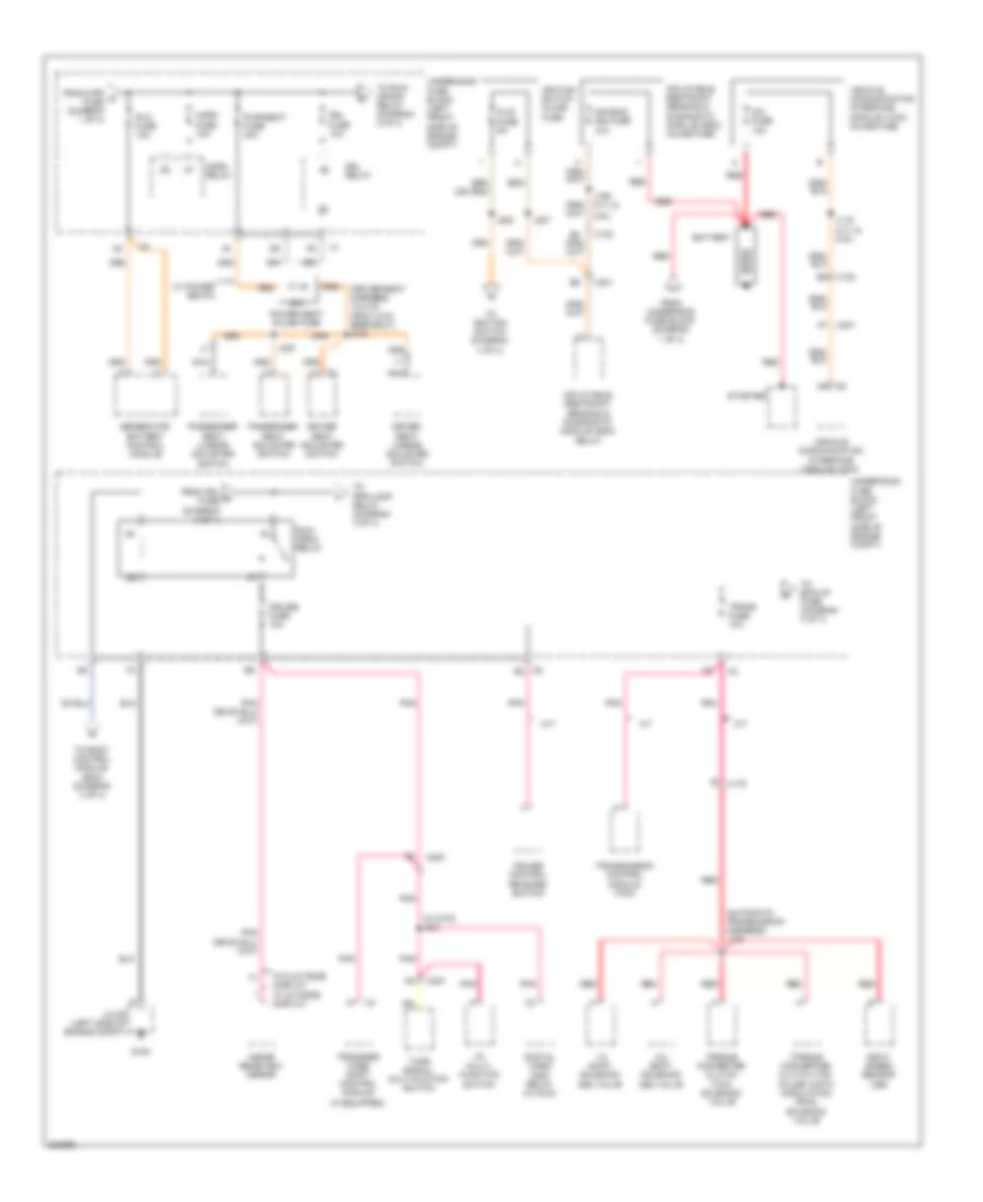
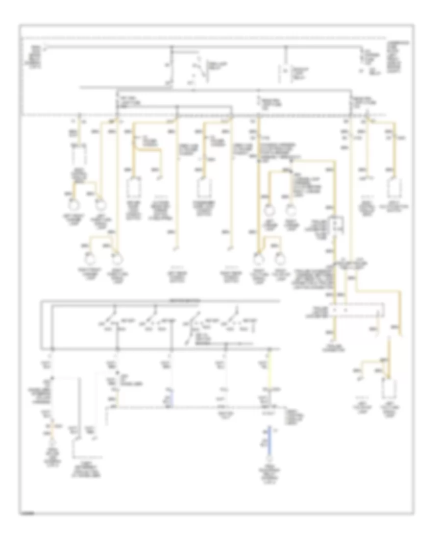
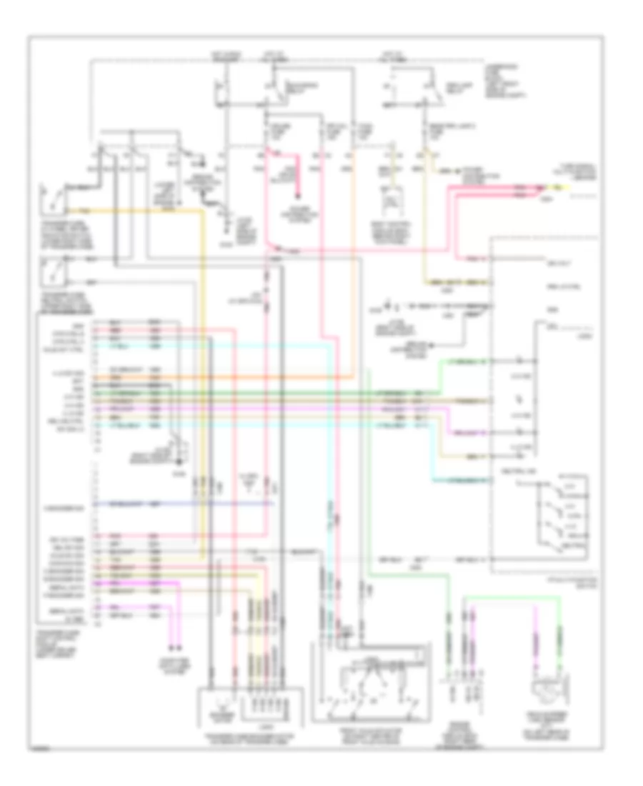
Power Distribution Wiring Diagram (2 of 4) for GMC Canyon 2012
List of elements for Power Distribution Wiring Diagram (2 of 4) for GMC Canyon 2012:
- (automatic transmission harness) j133
- (driver seat harness, 12.5 cm from x319 breakout) j312
- (if equipped)
- (iss)
- (w/ dvd) j331
- 1-2 shift solenoid (ss) valve
- 2-3 shift solenoid (ss) valve
- 20a
- A/t
- Air bag/ ign fuse 10a
- B5 x102
- Battery
- Cim fuse 10a
- Cruise control release switch
- Cruise fuse 10a
- Digital video disc relay (w/ dvd)
- Dlis fuse 5a
- Driver seat adjuster switch
- Driver seat lumbar adjuster switch
- Drl fuse 10a
- Drl relay
- From drl d fuse (diagram 2 of 4)
- From underhood fuse block (diagram 1 of 4)
- From wpr c fuse (diagram 1 of 4)
- G105
- Generator battery control module
- Horn fuse 10a
- Horn relay
- I/p multi- function switch
- Ignition switch inline fuse
- Inflatable restraint sensing & diagnostic module (sdm) inline fuse
- Inflatable restraint sensing & diagnostic module (sdm) relay
- Input speed sensor
- Inside rearview mirror
- J106 (3.7l &
- J119 (3.7l & 2.9l)
- J207
- J208
- J323
- Jx105 (left side of engine compt)
- M/t
- Nca
- Passenger seat adjuster switch
- Passenger seat lumbar adjuster switch
- Pnk
- Power seat inline fuse
- Pwr/seat fuse 40a
- Red
- Run/ crnk relay
- Rvc fuse 10a
- Starter
- To bck/up fuse (diagram 3 of 4)
- To body control module (bcm) (diagram 4 of 4)
- To ignition switch (diagram 4 of 4)
- To prk/lamp relay (diagram 4 of 4)
- To run/ crank relay (diagram 2 of 4)
- Torque converter clutch (tcc) pulse width modulation (pwm) solenoid valve
- Torque converter clutch (tcc) solenoid valve
- Trans fuse 10a
- Transfer case shift control module
- Transmission control module (tcm)
- Turn signal/ multi-fuction switch
- Underhood fuse block (left front side of engine compt)
- Vehicle communication interface module (vcim)
- Vehicle communication interface module (vcim) inline fuse
- W/ power seats
- W/o outside display w/ outside display
- X102
- X175
- X200
- X201
- X201 a7
- X204
- X6 b3
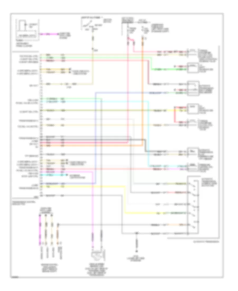
Power Distribution Wiring Diagram (3 of 4) for GMC Canyon 2012
List of elements for Power Distribution Wiring Diagram (3 of 4) for GMC Canyon 2012:
- (engine harness, 18 cm front generator pnk
- (fuel injector harness, 4 cm from fuel injector 4 breakout) j104
- (not used)
- 3.7l
- 3.7l & 2.9l
- 5.3l
- A/c relay
- Abs fuse 10a
- Battery control module) j107
- Bck/up fuse 15a
- Engine control module (ecm)
- Erls fuse 15a
- Evaporative emission (evap) canister purge solenoid valve
- Except
- Except 5.3l
- From e trans fuse (diagram 2 of 4)
- From ign g fuse (diagram 3 of 4)
- Front drive axle actuator
- Frt/axl fuse 15a
- Fuel injector
- Fuel injector 1
- Fuel injector 3
- Fuel injector 5
- Fuel injector 7
- Fuel pump flow control module
- Ign fuse 15a
- Ignition coil 1
- Ignition coil 2
- Ignition coil 3
- Ignition coil 4
- Ignition coil 4 (3.7l & 2.9l)
- Ignition coil 5
- Ignition coil 5 (3.7l)
- Ignition coil 6
- Ignition coil 7
- Ignition coil 8
- Inj fuse 15a
- J111
- J112
- J116
- Mass air flow (maf)/ intake air temperature (iat) sensor
- Pcm 1 fuse 10a
- Pnk
- Secondary air injection (air) pump relay (3.7l & 2.9l)
- To inj fuse (diagram 3 of 4)
- Underhood fuse block (left front side of engine compt)
- W/ electric air injection reactor system
- W/ two speed transfer case
- X102 c8
- X125 p
- X2 b2
- X2 c3
- X7 f3
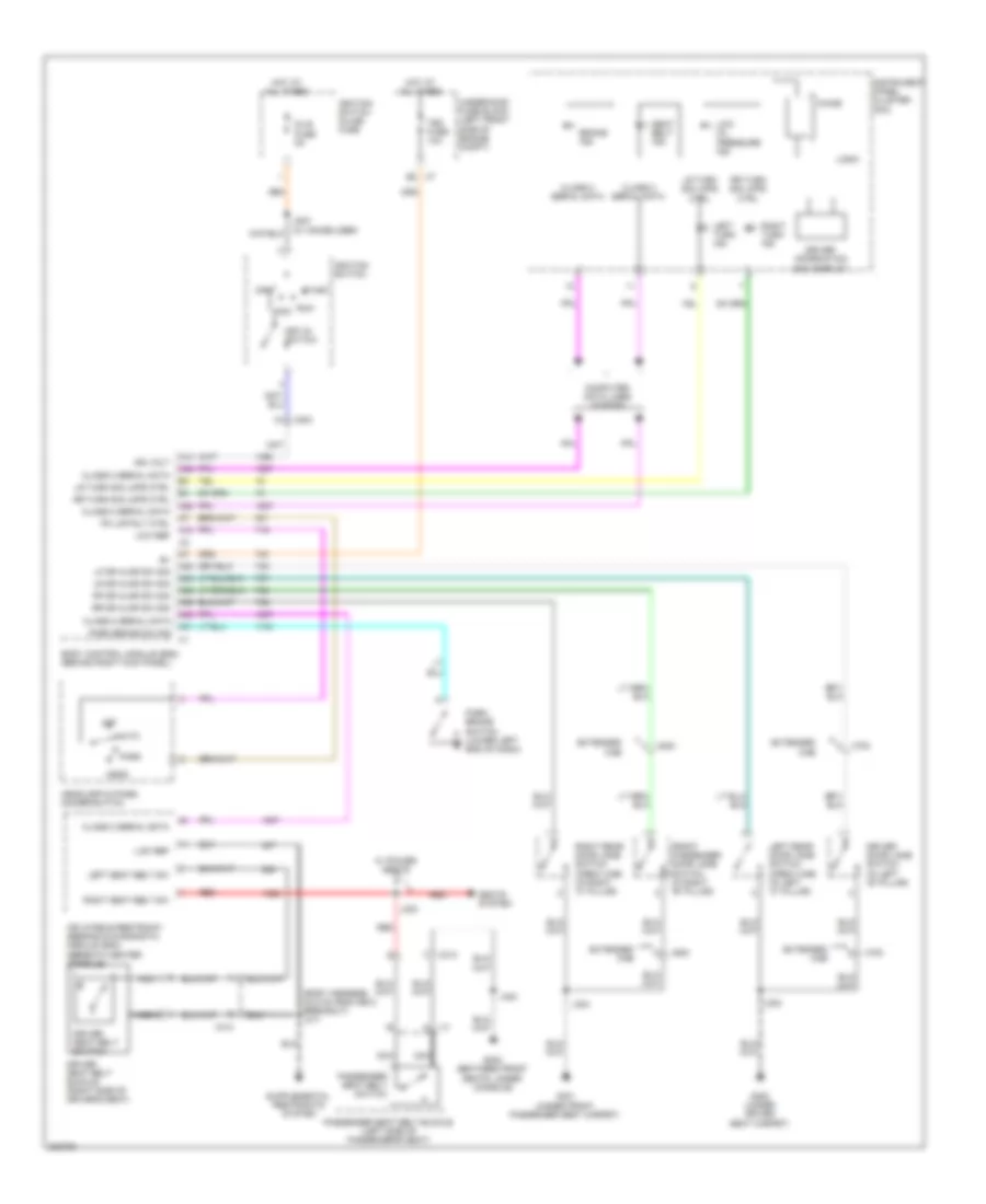
Power Distribution Wiring Diagram (4 of 4) for GMC Canyon 2012
List of elements for Power Distribution Wiring Diagram (4 of 4) for GMC Canyon 2012:
- (chassis harness, 40.5 cm from fuel pump & sender assembly breakout) j400
- 5 volt
- A/c cmprsr fuse 10a
- A/c relay
- A14
- A24
- Acc
- B3 x204
- Backup lamp relay
- Body control module (bcm)
- C11
- Crew cab w/ power window
- Driver door lock/ window switch
- F11
- From f run/ crank relay (diagram 2 of 4)
- From run/crank relay (diagram 2 of 4)
- From splice j208 (diagram 2 of 4)
- Frt prk lamp fuse 10a
- Ignition switch
- Ignition volt
- Input multi-function switch
- J203 (w/ immobilizer) (steering column harness)
- J204 (w/ immobilizer)
- J406 (trailer accessory harness, between left rear tail lamp connector & trailer lighting connector)
- J900 (license lamp harness, 44.5 cm before right license lamp)
- Key in ignition switch
- Left front marker lamp
- Left license lamp
- Left park/turn signal lamp
- Left rear window switch
- Left tail/stop lamp
- Left tail/turn signal lamp
- Off
- Outside rearview mirror switch (if equipped)
- Passenger door lock/ window switch
- Prk/lamp relay
- Rear prk lamp 2 fuse 10a
- Rear prk lamp fuse 15a
- Right front marker lamp
- Right license lamp
- Right park/turn signal lamp
- Right rear window switch
- Right tail/stop lamp
- Right tail/turn signal lamp
- Run
- Start
- Theft deterrent module (tdm) (w/ immobilizer)
- Trailer connector
- Trailer lighting converter
- Trailer lighting converter inline fuse
- Underhood fuse block (left front side of engine compt)
- W/ power window
- W/ trailer tow
- W/o trailer tow
- X1 a48
- X102
- X2 a42
- X200
- X204 b1
- X600
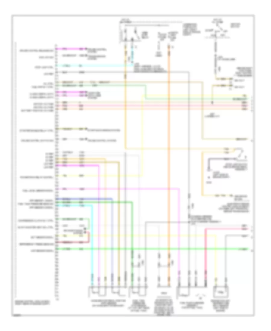
POWER DOOR LOCKS
Power Door Locks Wiring Diagram, Crew Cab for GMC Canyon 2012
List of elements for Power Door Locks Wiring Diagram, Crew Cab for GMC Canyon 2012:
- (body harness, 10.5 cm from accelerator pedal position switch breakout) j308
- (not used)
- A11
- A12
- A38
- A39
- A41
- A42
- A44
- A47
- All doors lock ctrl
- All doors unlock ctrl
- Batt pos volt
- Battery +
- Body control module (bcm) (behind right kick panel)
- Class 2 serial data
- Computer data lines system
- Door unlock
- Door unlock ctrl
- Door unlock relay
- Dr unlock pcb relay (except on star w/o driver convenience iii sales package)
- Dr/lck fuse 20a
- Driver door lock actuator (in lower rear of door)
- Driver door lock/window switch
- Driver door unlock ctrl
- Front passenger door lock actuator (in lower rear of door)
- G105
- G106
- G301 (under front passenger seat carpet)
- Ground
- Ground distribution system
- Hot at all times
- J304
- J309 (body harness, 17 cm from accelerator pedal position switch breakout)
- J500
- J501
- Jx105 (left side of engine compt)
- Jx106 (right side of engine compt)
- Left rear door lock actuator (in lower rear of door)
- Lock pcb relay
- Lock sw
- Lock switch
- Logic
- Pass door lock ctrl
- Passenger door lock/ window switch
- Right rear door lock actuator (in lower rear of door)
- Tan
- Tbc fuse 10a
- Trn/ hazrd frt fuse 15a
- Trn/ hazrd rear fuse 15a
- Underhood fuse block (left front side of engine compt)
- Unlock pcb relay
- Unlock sw
- Unlock switch
- W/ driver convenience iii sales package)
- W/o driver convenience iii sales package)
- X500
- X501
- X600
- X601
- X7 b3
- X700
- X800
Power Door Locks Wiring Diagram, Except Crew Cab for GMC Canyon 2012
List of elements for Power Door Locks Wiring Diagram, Except Crew Cab for GMC Canyon 2012:
- (not used)
- 87a
- A11
- A12
- A38
- A39
- A41
- A42
- A44
- A47
- All doors lock ctrl
- All doors unlock ctrl
- Batt pos volt
- Battery +
- Body control module (bcm) (behind right kick panel)
- Class 2 serial data
- Computer data lines system
- Door unlock
- Door unlock ctrl
- Door unlock relay
- Dr unlock relay (except on star w/o driver convenience iii sales package)
- Dr/lck fuse 20a
- Driver door lock actuator (in lower rear of door)
- Driver door lock/window switch
- Driver door unlock ctrl
- Front passenger door lock actuator (in lower rear of door)
- G105
- G106
- G301 (under front passenger seat carpet)
- Ground
- Ground distribution system
- Hot at all times
- J304
- J500
- J501
- Jx105 (left side of engine compt)
- Jx106 (right side of engine compt)
- Lock relay
- Lock sw
- Lock switch
- Logic
- Pass door lock ctrl
- Passenger door lock/ window switch
- Tan
- Tbc fuse 10a
- Trn/ hazrd frt fuse 15a
- Trn/ hazrd rear fuse 15a
- Underhood fuse block (left front side of engine compt)
- Unlock relay
- Unlock sw
- Unlock switch
- W/ driver convenience iii sales package)
- W/o driver convenience iii sales package)
- X500
- X501
- X600
- X601
- X7 b3
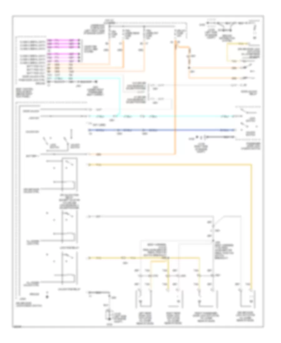
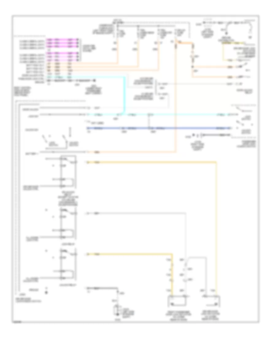
POWER MIRRORS
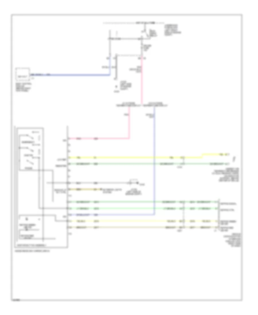
Automatic Day/Night Mirror Wiring Diagram for GMC Canyon 2012
List of elements for Automatic Day/Night Mirror Wiring Diagram for GMC Canyon 2012:
- Ambient air temperature sensor (w/ dual reading lamps) (on radiator support, behind center of grille)
- B5 x6
- Backup lp rly ctrl
- Body control module (behind right kick panel)
- Cruise fuse 10a
- Emergency
- Exterior lights system
- G105
- Hot at all times
- Ign
- Ign volt
- Inside rearview mirror (isrvm)
- Jx105 (left side of engine compt)
- Keypad ctrl
- Keypad green led ind
- Keypad green led sig
- Keypad red led ind
- Keypad red led sig
- Keypad signal
- Low ref
- Onstar
- Onstar button assembly
- Phone
- Pnk
- Resister
- Run/ crnk relay
- Underhood fuse block (left front side of engine compt)
- Vehicle communication interface module (vcim) (right side of dash)
- W/ outside temperature display
- W/o outside temperature display
- X104
- X201
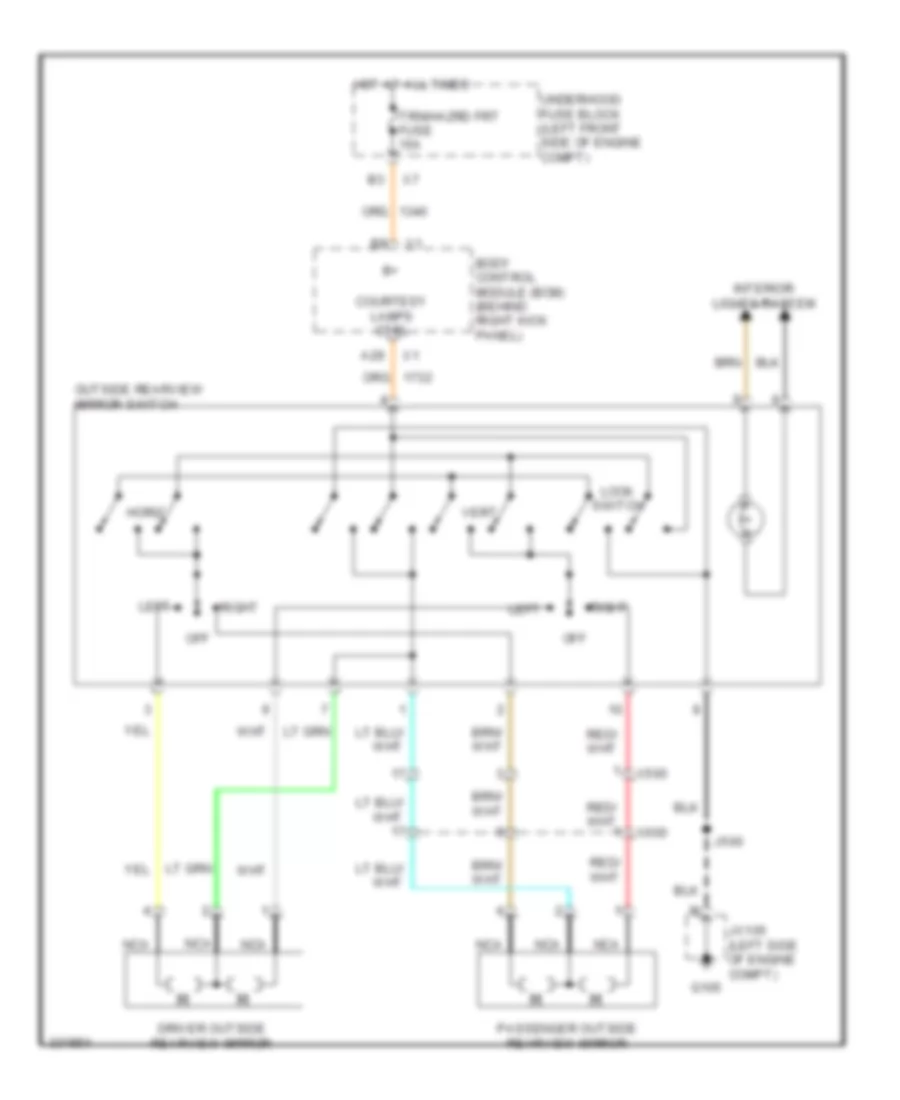
Power Mirrors Wiring Diagram for GMC Canyon 2012
List of elements for Power Mirrors Wiring Diagram for GMC Canyon 2012:
- A29
- Body control module (bcm) (behind right kick panel)
- Courtesy lamps ctrl
- Driver outside rearview mirror
- G105
- Horiz
- Hot at all times
- Interior lights system
- J500
- Jx105 (left side of engine compt)
- Left
- Lock switch
- Nca
- Off
- Outside rearview mirror switch
- Passenger outside rearview mirror
- Right
- Trn/hazrd frt fuse 15a
- Underhood fuse block (left front side of engine compt)
- Vert
- X500
- X600
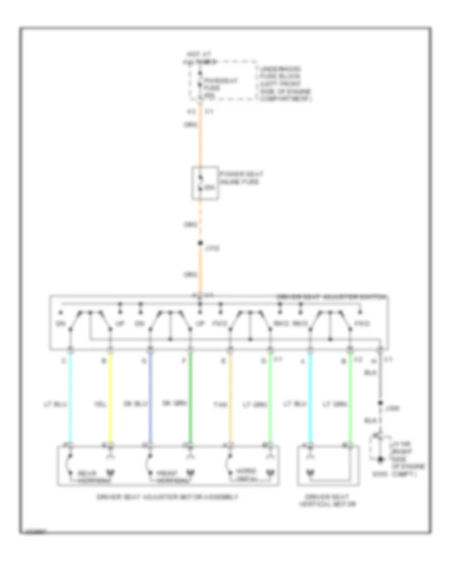
POWER SEATS
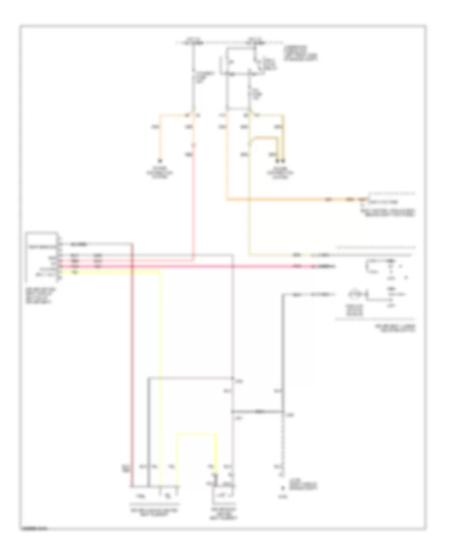
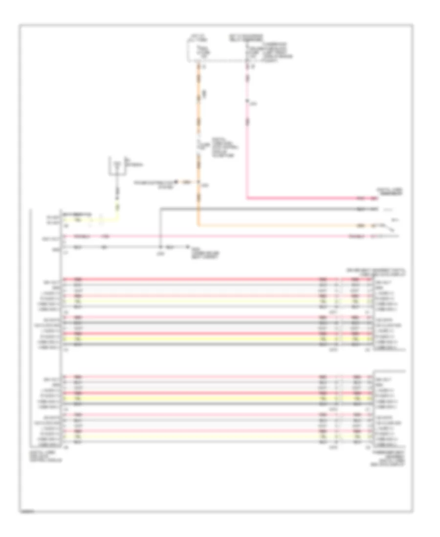
Driver Heated Seat Wiring Diagram for GMC Canyon 2012
List of elements for Driver Heated Seat Wiring Diagram for GMC Canyon 2012:
- 2009-gm-29-26
- A/c fuse 10a
- A26
- Body control module (bcm) (behind right kick panel)
- Driver back heated seat element
- Driver cushion heated seat element
- Driver heated seat module (bottom of driver seat)
- Driver seat lumbar adjuster switch
- F10
- G106
- Gnd
- Hi/lo sig
- High
- High/low status ind bulb
- Hot at all times
- Htd/seat fuse 20a
- Ign 3 hvac relay
- Ign 3 voltage
- J306
- J321
- J322
- Jx106 (right side of engine compt)
- Low
- Nca
- Pnk
- Power distribution system
- Red
- Sply volt
- Temp sens sig
- Underhood fuse block (left front side of engine compt)
Driver Power Seat Wiring Diagram for GMC Canyon 2012
List of elements for Driver Power Seat Wiring Diagram for GMC Canyon 2012:
- 20a
- Driver seat adjuster motor assembly
- Driver seat adjuster switch
- Driver seat vertical motor
- Front vertical
- Fwd
- G106
- Horiz- ontal
- Hot at all times
- J306
- J312
- Jx106 (right side of engine compt)
- Power seat inline fuse
- Pwr/seat fuse 40a
- Rear vertical
- Rwd
- Tan
- Underhood fuse block (left front side of engine compartment)
Lumbar Wiring Diagram for GMC Canyon 2012
List of elements for Lumbar Wiring Diagram for GMC Canyon 2012:
- 20a
- Driver seat lumbar adjuster switch
- Driver seat lumbar motor (in bottom of driver seat)
- G106
- Hot at all times
- J306
- J312
- J314
- J323
- Jx106 (right side of engine compt)
- Nca
- Out
- Passenger seat lumbar adjuster switch
- Passenger seat lumbar motor (bottom of front passenger seat)
- Pnk
- Power seat inline fuse
- Pwr/seat fuse 40a
- Underhood fuse block (left front side of engine compt)
Passenger Power Seat Wiring Diagram for GMC Canyon 2012
List of elements for Passenger Power Seat Wiring Diagram for GMC Canyon 2012:
- 20a
- Front vertical
- Fwd
- G106
- Horiz- ontal
- Hot at all times
- J314
- J323
- Jx106 (right side of engine compt)
- Passenger seat adjuster motor assembly
- Passenger seat adjuster switch
- Power seat inline fuse
- Pwr/seat fuse 40a
- Rear vertical
- Rwd
- Tan
- Underhood fuse block (left front side of engine compartment)
Passenger"s Heated Seat Wiring Diagram for GMC Canyon 2012
List of elements for Passenger"s Heated Seat Wiring Diagram for GMC Canyon 2012:
- 2009-gm-29-27
- A/c fuse 10a
- A26
- Body control module (bcm) (behind right kick panel)
- F10
- Front passenger heated seat module (bottom of front passenger seat)
- G106
- Gnd
- Hi/lo sig
- High
- High/low status ind bulb
- Hot at all times
- Htd/seat fuse 20a
- Ign 3
- Ign 3 hvac relay
- Ign 3 voltage
- J314
- J317
- J318
- Jx106 (right side of engine compt)
- Logic
- Low
- Nca
- Passenger back heated seat element
- Passenger cushion heated seat element
- Passenger seat lumbar adjuster switch
- Pnk
- Power distribution system
- Red
- Rt seat belt sw
- Sply volt
- Temp sens sig
- Underhood fuse block (left front side of engine compt)
POWER WINDOWS
Power Windows Wiring Diagram, 2 Door for GMC Canyon 2012
List of elements for Power Windows Wiring Diagram, 2 Door for GMC Canyon 2012:
- (not used)
- 87a
- Auto
- Down
- Down pcb relay
- Down relay
- Dr/lck fuse 20a
- Driver door lock/ window switch
- Driver window motor (in lower front of door)
- G105
- G106
- Hot at all times
- Hot w/ rap relay energized
- Ign
- J500
- Jx105 (left side of engine compt)
- Jx106 (right side of engine compt)
- Logic
- Passenger door lock/ window switch
- Passenger window motor (in lower front of door)
- Pwr/ wndw fuse 30a
- Rf down
- Rf up
- Tan
- Underhood fuse block (left front side of engine compt)
- Up pcb relay
- Up relay
- X500
- X600
Power Windows Wiring Diagram, 4 Door for GMC Canyon 2012
List of elements for Power Windows Wiring Diagram, 4 Door for GMC Canyon 2012:
- (body harness, 4 cm from accelerator pedal position breakout) j307
- Auto
- Down
- Down pcb relay
- Dr/lck fuse 20a
- Driver door lock/ window switch
- Driver window motor (in lower front of door)
- Dwn
- G105
- G106
- Hot at all times
- Hot w/ rap relay energized
- Interior lights system
- J302
- J500
- Jx105 (left side of engine compt)
- Jx106 (right side of engine compt)
- Left rear window motor (in lower center of door)
- Left rear window switch
- Logic
- Lr down
- Lr up
- Passenger door lock/ window switch
- Passenger window motor (in lower front of door)
- Pwr/ wndw fuse 30a
- Rf down
- Rf up
- Right rear window motor (in lower center of door)
- Right rear window switch
- Rr down
- Rr up
- Tan
- Underhood fuse block (left front side of engine compt)
- Up pcb relay
- W/l
- X4 a
- X500
- X6 f5
- X600
- X700
- X800
RADIO
Radio Wiring Diagram for GMC Canyon 2012
List of elements for Radio Wiring Diagram for GMC Canyon 2012:
- A10
- A11
- A12
- Audio comm sig
- B10
- B11
- B12
- Coax
- Common sig
- Computer data lines system
- Crew cab
- Digital radio antenna
- Digital radio receiver (if equipped) (center of dash)
- Digital video disc (dvd) control module inline fuse
- Drain wire
- Extended cab
- Extended cab crew cab
- Fuse 5a
- G300 (under driver seat carpet)
- Ground
- Hot at all times
- J201
- J332
- Left aud sig
- Left audio sig
- Left front speaker
- Left front tweeter speaker (w/ 6 speakers system)
- Left rear speaker (w/ extended cab & crew cab)
- Lf out +
- Lf out -
- Lr out +
- Lr out -
- Nca
- Radio
- Radio antenna
- Rdo fuse 15a
- Rf out +
- Rf out -
- Right aud sig
- Right front speaker
- Right front tweeter speaker (w/ 6 speakers system)
- Right rear speaker (w/ extended cab & crew cab)
- Rr out +
- Rr out -
- Satellite in
- Serial data
- Tan
- Underhood fuse block (left front side of engine compt)
- Vehicle communication interface module (vcim) (w/ onstar) (right side of dash)
- W/ spo dvd
- W/o spo dvd
- X200
- X201
- X211
- X270
- X500
- X600
- X700
- X800
Video System Wiring Diagram for GMC Canyon 2012
List of elements for Video System Wiring Diagram for GMC Canyon 2012:
- 12c clock sig
- 12c data
- Acc volt
- Cruise fuse 10a
- Digital video disc (dvd) control module
- Digital video disc (dvd) control module inline fuse
- Digital video disc relay
- Driver seat headrest digital video disc (dvd) display
- Fm ant
- Fm antenna
- Fuse 5a
- G300 (under driver seat carpet)
- Gnd
- Hot at all times
- Hot w/ run/crank relay energized
- I2c data
- Ign volt
- J330
- J331
- J332
- L audio (+)
- Passenger seat headrest digital video disc (dvd) display
- Pnk
- Power distribution system
- R audio (+)
- Rdo fuse 15a
- Red
- Underhood fuse block (left front side of engine compt)
- Video sig (+)
- Video sig (-)
- X200
- X371
- X372
- X373
- X374
SHIFT INTERLOCK
Shift Interlock Wiring Diagram for GMC Canyon 2012
List of elements for Shift Interlock Wiring Diagram for GMC Canyon 2012:
- (not used)
- A/t shift lock control solenoid (under center console, left side of shifter)
- A11
- A31
- A4 x204
- A47
- Abs brake switch signal
- Automatic transmission
- Automatic transmission internal mode switch (ims)
- B2 x7
- B4 x1
- B4 x204
- Body control module (behind right kick panel)
- Class 2 serial data
- Computer data lines system
- Data bus (+)
- Data bus (-)
- Electronic brake control module (ebcm) (on inner left frame rail, beside transmission)
- Engine control module (ecm) (right rear of engine compt)
- Exterior lights system
- G102 (lower left side of engine)
- G105
- G106
- Hot at all times
- J100 (body harness, 14.5 cm from accelerator pedal position switch breakout)
- J110
- J200
- Jx105 (left side of engine compt)
- Jx106 (right side of engine compt)
- M x104
- P/n sig
- Ser data +
- Ser data -
- Serial data
- Sol ctrl
- St lp ctrl
- Stop fuse 20a
- Stop lamp switch (above brake pedal assembly)
- Sw sig a
- Sw sig b
- Sw sig c
- Sw sig p
- Tan
- Tbc fuse 10a
- Transmission control module (tcm)
- Underhood fuse block (left front side of engine compt)
- Vses/stop relay
STARTING/CHARGING
Charging Wiring Diagram for GMC Canyon 2012
List of elements for Charging Wiring Diagram for GMC Canyon 2012:
- (right rear of engine compt) engine control module (ecm)
- A11
- B11
- Battery
- Charge ind
- Computer data lines system
- Driver information center (dic) display
- Field duty cyc
- G100 (next to rear side of battery)
- G102 (lower left side of engine)
- G104 (left side of engine)
- Gen reg cntrl
- Gen turn on
- Generator
- Generator battery control module (left front of engine compt, near battery)
- Gnd
- Ground
- Instrument panel cluster (ipc)
- J106
- Logic
- Mega fuse 125a
- Power distribution system
- Red
- Rvc fuse 10a
- Serial data
- Starter
- Underhood fuse block (left front side of engine compt)
- X10
- X11
Starting Wiring Diagram for GMC Canyon 2012
List of elements for Starting Wiring Diagram for GMC Canyon 2012:
- 5v ref
- A14
- A42
- A42 key resistor sig
- A47
- Acc
- Automatic transmission (a/t)
- B11
- Battery
- Body control module (bcm) (behind right kick panel)
- C11
- Clutch pedal position (cpp) sensor (m/t)
- Computer data lines system
- Cpp sig
- Engine control module (ecm) (right rear of engine compt)
- G100 (next to rear side of battery)
- G102 (lower left side of engine)
- G104 (left side of engine)
- Ign volt x2
- Ignition switch
- Internal mode switch
- J110 (a/t)
- Low ref
- Off
- Park/
- Red
- Run
- Serial
- Serial data
- Serial data x1
- Start
- Starter
- Strtr fuse 30a
- Strtr relay
- Underhood fuse block (left front side of engine compt)
- X1 ctrl rly
- X1 data
- X10
- X204
- X3 signal neutral
SUPPLEMENTAL RESTRAINTS
Supplemental Restraints Wiring Diagram (1 of 2) for GMC Canyon 2012
List of elements for Supplemental Restraints Wiring Diagram (1 of 2) for GMC Canyon 2012:
- (right side of engine compt, behind air cleaner)
- 10a
- A2 x275
- Air bag off ind
- Air bag on ind
- Anti-theft system
- Body control module (bcm) (behind right kick panel)
- C12
- Computer data lines system
- Cruise fuse 10a
- G106
- G302 (between front seats, under console)
- Ground
- High control
- Hot at all times
- Hot w/ run/crank relay energized
- I/p multi- function switch
- Ign volt
- Inflatable restraint i/p module (right side of dash)
- Inflatable restraint sensing & diagnostic module (beneath center console)
- Inflatable restraint sensing & diagnostic module (sdm) inline fuse
- Inflatable restraint sensing & diagnostic module (sdm) relay
- Inflatable restraint steering wheel module (top of steering wheel)
- Inflatable restraint steering wheel module coil
- J106 (except 5.3l)
- J200
- J324
- Jx106
- Left front seat belt pretensioner (extended cab: in left rear door) (regular/crew cab: in left "b" pillar)
- Lh seat belt sw
- Low control
- Low reference
- Passenger seat belt indicator
- Pnk
- Red
- Rh seat belt sw
- Right front seat belt pretensioner (extended cab: in right rear door) (regular/crew cab: in right "b" pillar)
- Serial data
- Shorting bar
- Signal
- Tan
- Underhood fuse block (left front side of engine compt)
- Voltage
- X200
- X201
- X204
Supplemental Restraints Wiring Diagram (2 of 2) for GMC Canyon 2012
List of elements for Supplemental Restraints Wiring Diagram (2 of 2) for GMC Canyon 2012:
- (between front seats, under console) g302
- (right side of dash) vehicle communication interface module (vcim)
- 5 volt ref
- A39
- A42
- Air bag ind
- Body control module (behind right kick panel)
- Driver inflatable restraint seat position sensor (on driver seat track)
- Driver seat belt buckle (right side of driver's seat)
- Driver seat belt switch
- G302 (between front seats, under console)
- Gnd
- Ign
- Ign 1+
- Inflatable restraint front passenger presence system (pps) module (under side of front passenger seat)
- Inflatable restraint front passenger presence system (pps) sensor (in front passenger seat cushion)
- Instrument panel cluster (ipc)
- Ipc class 2 serial data
- J311 (body harness, 24.5 cm from g302 breakout)
- J323
- J324
- Left inflatable restraint front end sensor (on left underside of front frame crossmember)
- Left inflatable restraint roof rail module (if equipped) (in roof above driver door)
- Left inflatable restraint side impact sensor (sis) (if equipped) (lower rear of driver door)
- Logic
- Low ref
- M x313
- Nca
- Off ind
- On ind
- Passenger inflatable restraint seat belt tension sensor
- Passenger inflatable restraint seat position sensor (on front passenger seat track)
- Passenger seat belt buckle (left side of passenger's seat)
- Passenger seat belt switch
- Passenger seat lumbar adjuster switch
- Pnk
- Press sig
- Red
- Right inflatable restraint front end sensor (on right underside of front frame crossmember)
- Right inflatable restraint roof rail module (if equipped) (in roof above front passenger door)
- Right inflatable restraint side impact sensor (sis) (if equipped) (lower rear of front passenger door)
- Seat belt ind
- Seat belt ind control
- Serial
- Shorting bar
- Tan
- Tension sig
- Volt ref
- W/ power seats
- W/ vehicle communication interface module
- W/o power seats
- W/o vehicle communication interface module
- X104
- X313
- X314
- X500
- X600
TRANSMISSION
A/T Wiring Diagram for GMC Canyon 2012
List of elements for A/T Wiring Diagram for GMC Canyon 2012:
- 1-2 shift sol ctrl
- 1-2 shift solenoid (ss) valve
- 2-3 shift sol ctrl
- 2-3 shift solenoid (ss) valve
- Acc
- Automatic transmission
- Automatic transmission fluid temperature (tft) sensor
- Automatic transmission input speed (iss) sensor
- Automatic transmission internal mode switch (ims)
- Computer data lines system
- Data bus +
- Data bus -
- Engine control module (ecm) (right rear of engine compt)
- Exterior lights system
- G102 (lower left side of engine)
- Gnd
- Hi spd serial data +
- Hi spd serial data -
- Hot at all times
- Hot w/ run/ crnk relay energized
- Ign serial data
- Ign volt
- Ignition switch
- In shaft spd sens
- Instrument panel cluster
- J110
- J133
- J209
- Lo ref
- Logic
- Off
- Park/
- Pc sol valve hi ctrl
- Pc sol valve lo ctrl
- Pnk
- Pressure control (pc) solenoid valve
- Red
- Run
- Serial data
- Start
- Stop lamp ctrl
- Tan
- Tcc pwm sol ctrl
- Tcc sol valve ctrl
- Tcm fuse 10a
- Tft sens sig
- Torque converter clutch (tcc) pulse width modulation (pwm) solenoid valve
- Torque converter clutch (tcc) solenoid valve
- Trans fuse 10a
- Trans range sw a
- Trans range sw b
- Trans range sw c
- Trans range sw p
- Transmission control module (tcm)
- Underhood fuse block (left front side of engine compt)
- Up shift ind
- Vehicle speed sensor (vss) (4wd: on left rear of transfer case) (2wd: left rear of transmission)
- Vss hi sig
- Vss lo sig
- X125
- X3 neutral sig
Transfer Case Wiring Diagram for GMC Canyon 2012
List of elements for Transfer Case Wiring Diagram for GMC Canyon 2012:
- (lower left side of engine) g103
- (not used) d
- (right side of engine compt)
- 12v
- 2 hi
- 2 hi ind
- 2wd/4wd sig
- 4 hi
- 4 hi ind
- 4 lo
- 4 lo ind
- 4 lo sw sig
- 5v ref
- A encoder sig
- A sig
- Axle act ctrl
- Axle sw sig
- B encoder sig
- B sig
- B2 x2
- Bat
- Body control module (bcm) (behind right
- C encoder sig
- C sig
- C10
- Computer data lines system
- Cruise fuse 10a
- Distribution
- Encoder motor
- Engine control module (ecm) (right rear of engine compt)
- F11
- Front axle actuator (on right center of front axle housing)
- Frt/axl fuse 15a
- G105
- G106
- Gnd
- Ground
- Ground distribution system
- Hot at all times
- Hot in run or start
- I/p multi-function switch
- Ign volt
- Ign voltage
- J200
- J331 (w/ spo dvd)
- Jx105 (left side of engine compt)
- Jx106
- Jx106 (right side of engine compt)
- Kick panel)
- Lo sig
- Logic
- Mtr ctrl a
- Mtr ctrl b
- Neu ind ctrl
- Neu sw sig
- Neutral
- Neutral ind
- P encoder sig
- P sig
- Pnk
- Power
- Power distribution system
- Prk lp ctrl
- Prk/lamp relay
- Rear prk lamp 2 fuse 10a
- Red
- Rly ctrl
- Run/crank relay
- Serial data
- Sig hi
- Sig lo
- Sw sig lo
- System
- Tan
- Tccm fuse 10a
- Transfer case 2/4 wheel driver indicator switch (lower right side of transfer case)
- Transfer case encoder motor (on rear of transfer case)
- Transfer case neutral switch (upper right side of transfer case)
- Transfer case shift control module (under driver seat carpet)
- Turn signal/ multi-function switch
- Underhood fuse block (left front side of engine compt)
- Vehicle speed (vss) sensor (m/t) (on left rear of transfer case)
- W/ spo dvd
- X1 a24
- X100
- X105
- X200
- X204
- X271
- X6 f1
WARNING SYSTEMS
Warning Systems Wiring Diagram for GMC Canyon 2012
List of elements for Warning Systems Wiring Diagram for GMC Canyon 2012:
- (body harness, 24.5 cm from g302 breakout) j311
- A10
- A14
- A31
- A32
- A38
- A39
- A42
- A44
- Acc
- Auto
- Body control module (bcm) (behind right kick panel)
- Brake ind
- Chime
- Class 2 serial data
- Computer data lines system
- Dlis fuse 5a
- Driver door jamb switch (in left "b" pillar)
- Driver information (dic) display
- Driver seat belt buckle (right side of driver's seat)
- Driver seat belt switch
- Extended cab
- Front passenger door jamb switch (in right "b" pillar)
- G300 (under driver seat carpet)
- G301 (under front passenger seat carpet)
- G302 (between front seats, under console)
- Head
- Headlamp & panel dimmer switch
- Hot at all times
- Ign volt
- Ignition switch
- Ignition switch inline fuse
- Inflatable restraint sensing & diagnostic module (sdm) (beneath center console)
- Instrument panel cluster (ipc)
- J303
- J304
- J323
- J324
- Key-in switch
- Left rear door jamb switch (crew cab) (in left "c" pillar)
- Left seat belt sw
- Left turn ind
- Lf dr ajar sw sig
- Logic
- Low oil pressure ind
- Low ref
- Lr dr ajar sw sig
- Lr turn sig lmps ctrl
- Nca
- Off
- Park
- Park brake sw sig
- Park brake switch (lower left end of dash)
- Passenger seat belt buckle (left side of passenger's seat)
- Passenger seat belt switch
- Pk lmp rly ctrl
- Red
- Rf dr ajar sw sig
- Right rear door jamb switch (crew cab) (in right "c" pillar)
- Right seat belt sw
- Right turn ind
- Rr dr ajar sw sig
- Rr turn sig lmps ctrl
- Run
- Seat belt ind
- Seats system
- Start
- Tbc fuse 10a
- Underhood fuse block (left front side of engine compt)
- W/ power seats
- X204
- X313
- X314
- X7 b2
- X700
- X800
WIPER/WASHER
Wiper/Washer Wiring Diagram for GMC Canyon 2012
List of elements for Wiper/Washer Wiring Diagram for GMC Canyon 2012:
- 87a
- A20
- B10
- Body control module (behind right kick panel)
- F12
- G105
- Hi in
- Hot at all times
- Int
- Jx105 (left side of engine compt)
- Lo in
- Mist
- Nca
- Off
- Park out
- Rap relay
- Rap relay coil control
- Red
- Turn signal/ multi-function switch
- Underhood fuse block (left front side of engine compt)
- Washer switch
- Windshield washer fluid pump (on washer fluid reservoir)
- Windshield washer pump control
- Windshield wiper motor (left rear of engine compt)
- Windshield wiper motor park switch signal
- Windshield wiper switch signal 1
- Windshield wiper switch signal 2
- Windshield wiper/ washer switch
- Wiper switch
- Wpr 2 relay
- Wpr fuse 25a
- Wpr relay
- Wsw fuse 10a
- X200
- X204

 Čeština
 Dansk
Dansk Deutsch
 Ελληνικά
 English
 English
 Español
 Suomi
Suomi Français
 Français
 עברית
עברית Hrvatski
 Magyar
 日本語
日本語 한국어
한국어 Nederlands
 Polski
 Português
 Português
 Română
 Русский
 Slovenčina
 Slovenščina
 Svenska
 Türkçe
 中文 (中国)