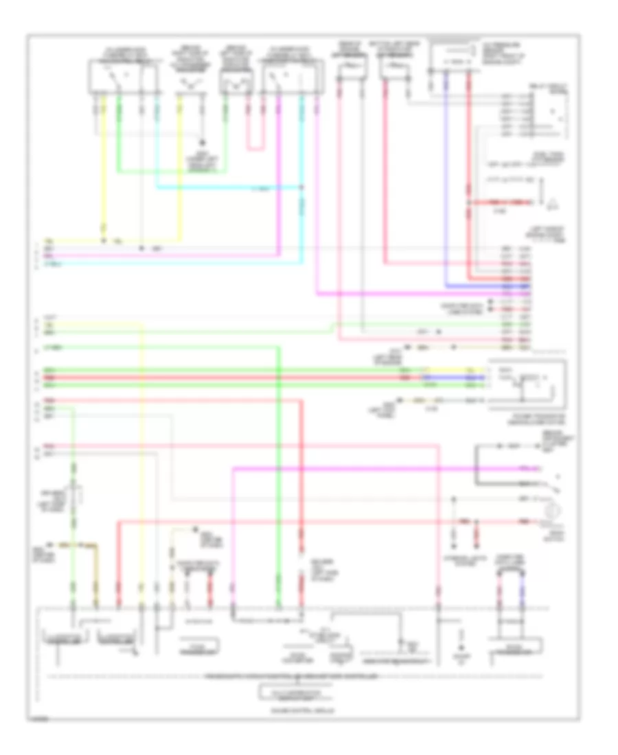
AIR CONDITIONING
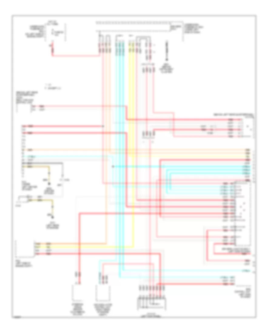
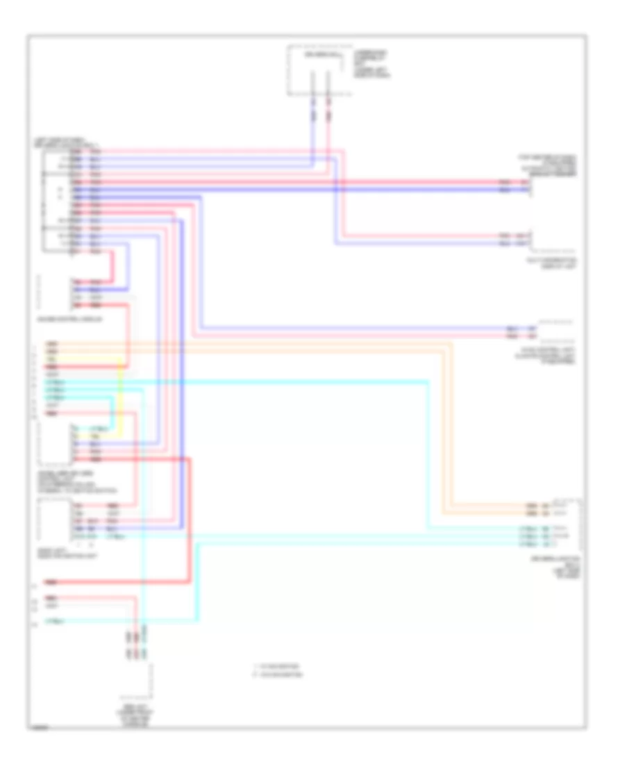
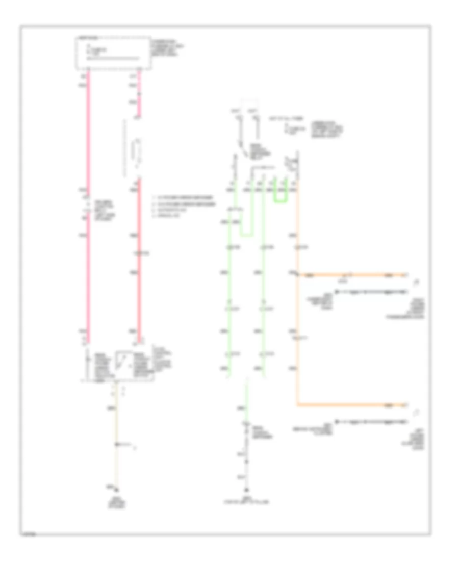
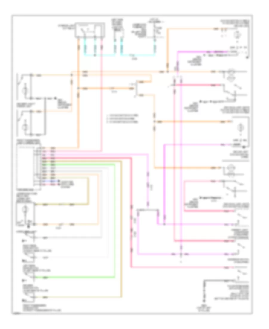
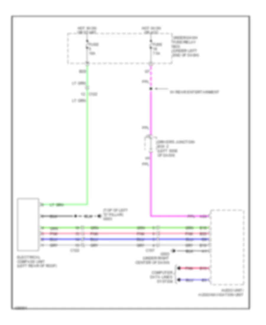
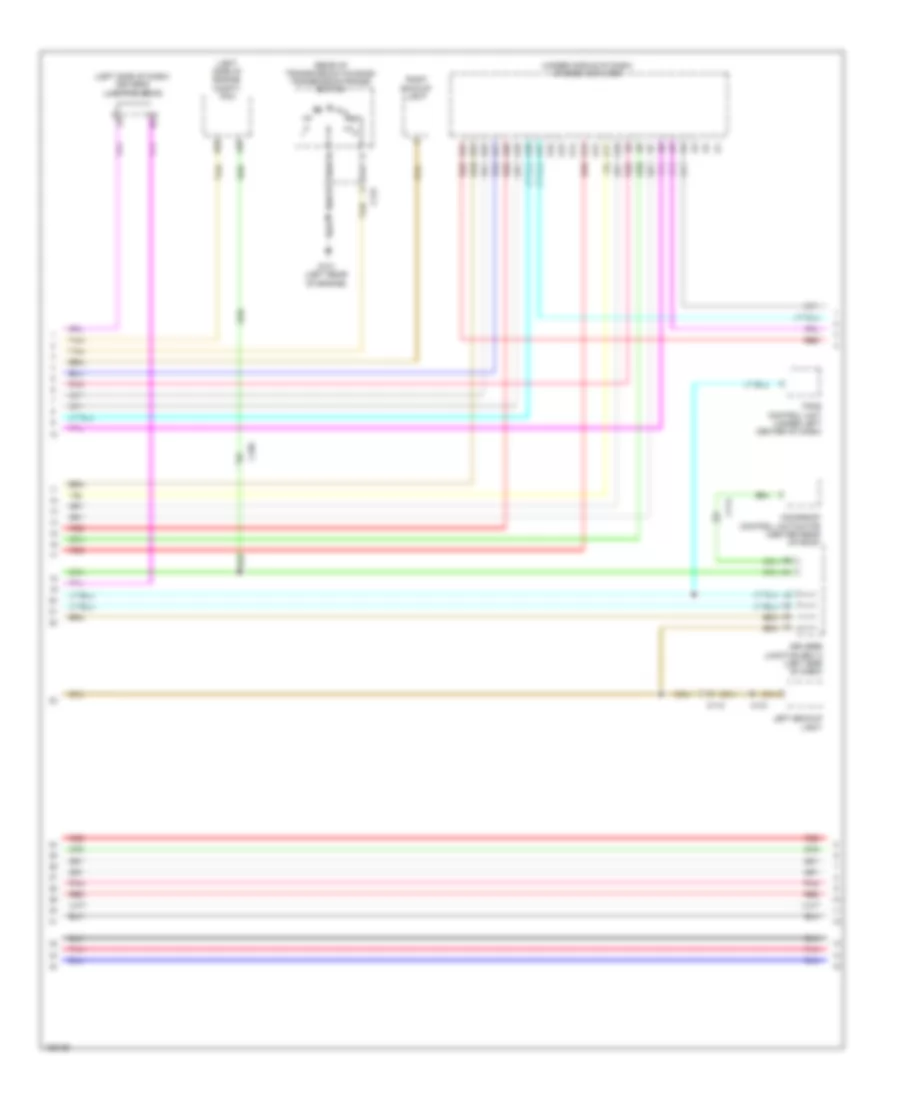
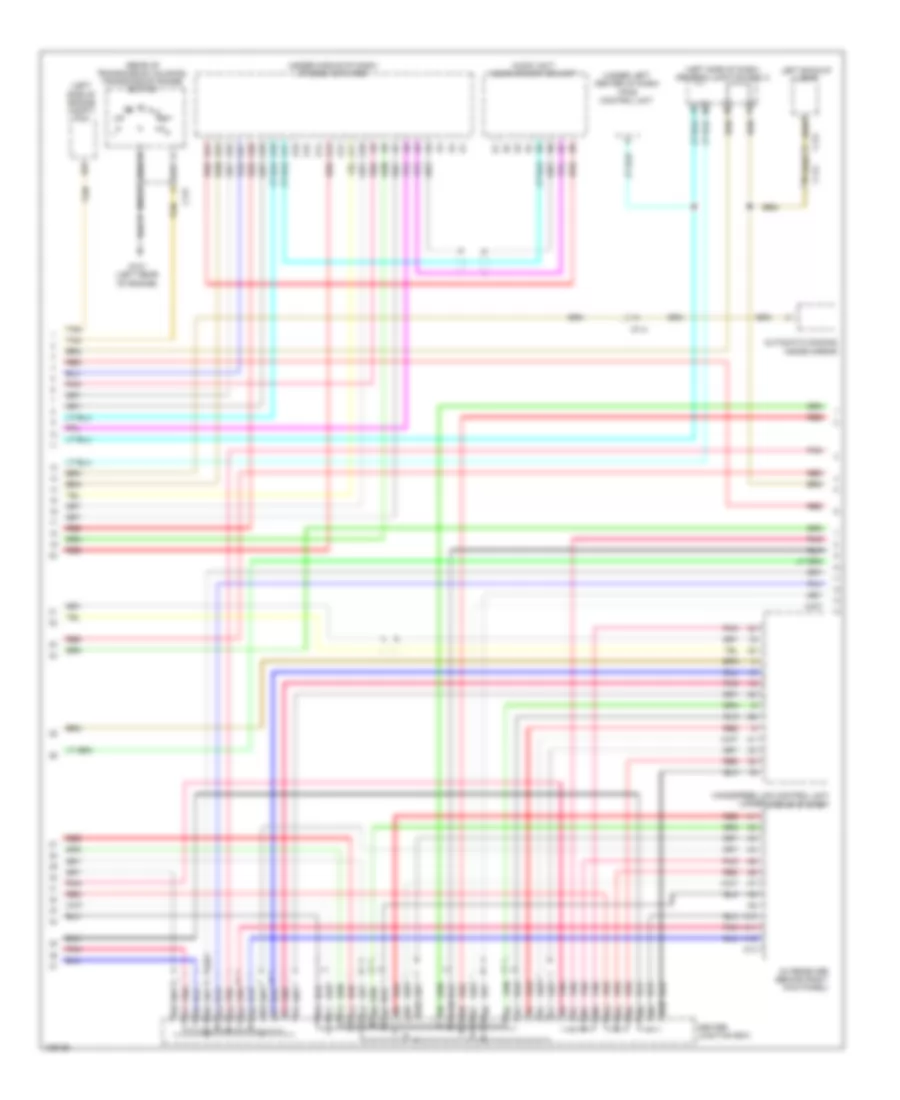
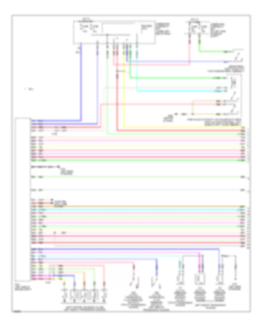
Automatic A/C Wiring Diagram (1 of 3) for Honda CR-V LX 2014
 https://portal-diagnostov.com/license.html
Automotive Electricians Portal FZCO
Automotive Electricians Portal FZCO
https://portal-diagnostov.com/license.html
https://portal-diagnostov.com/license.html
Automotive Electricians Portal FZCO
Automotive Electricians Portal FZCO
List of elements for Automatic A/C Wiring Diagram (1 of 3) for Honda CR-V LX 2014:
- (center of dash) g502
- 10a
- 7.5a
- Automatic lighting/ sunlight sensor (top center of dash)
- B42
- B43
- C106
- C108
- C12
- C17
- C19
- Computer data lines system
- D17
- D28
- D31
- Driver's air mix control motor (left side of hvac unit)
- Driver's j/b 2 (left side of dash)
- Engine controls system
- Evaporator temperature sensor (on evaporator)
- Fuse
- Fuse 7.5a
- G502 (center of dash)
- Hot in on
- Hot in on or start
- Hvac control unit/ climate control unit
- Micu
- Mode control motor (right side of hvac unit)
- Passenger's air mix control motor (lower right side of hvac unit)
- Pgm-fi sub relay
- Pnk
- Q16
- Rear window defogger relay
- Rear window defogger switch/ power mirror defogger switch
- Rear window defogger switch/ power mirror defogger switch indicator (led)
- Recirculation control motor (upper left side of blower unit)
- Red
- Relay circuit board
- Tail light relay
- Under-dash fuse/relay box (under left end of dash)
- Under-hood fuse/relay box (on left side of engine compt)
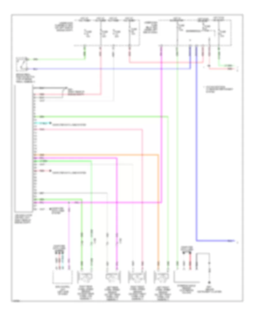
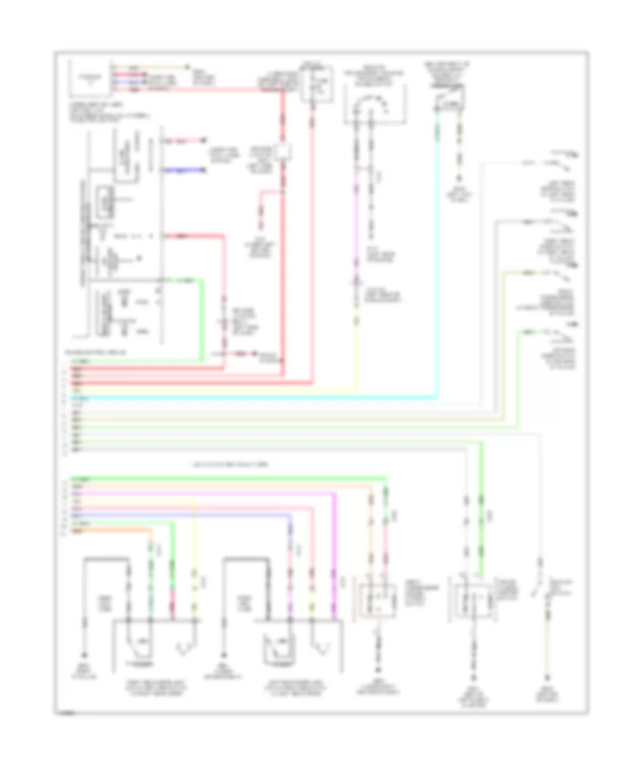
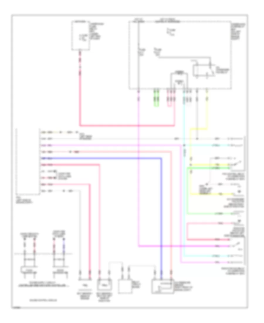
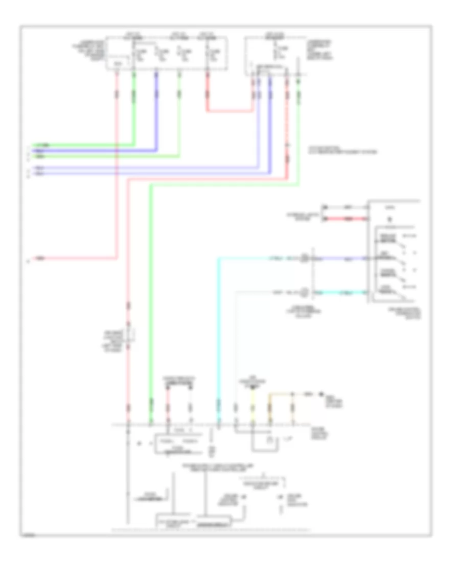
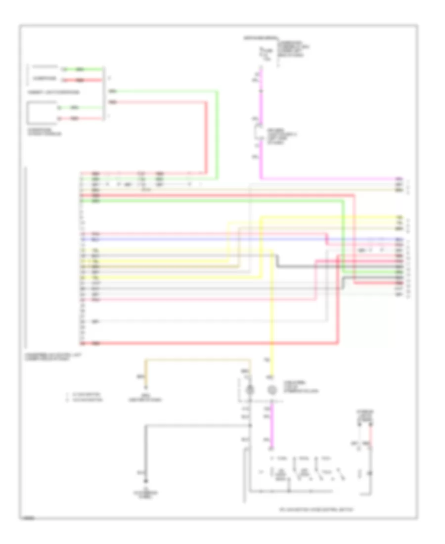
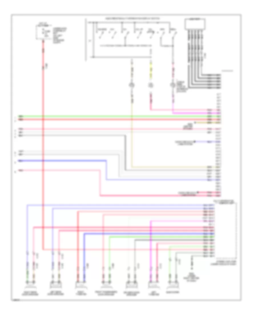
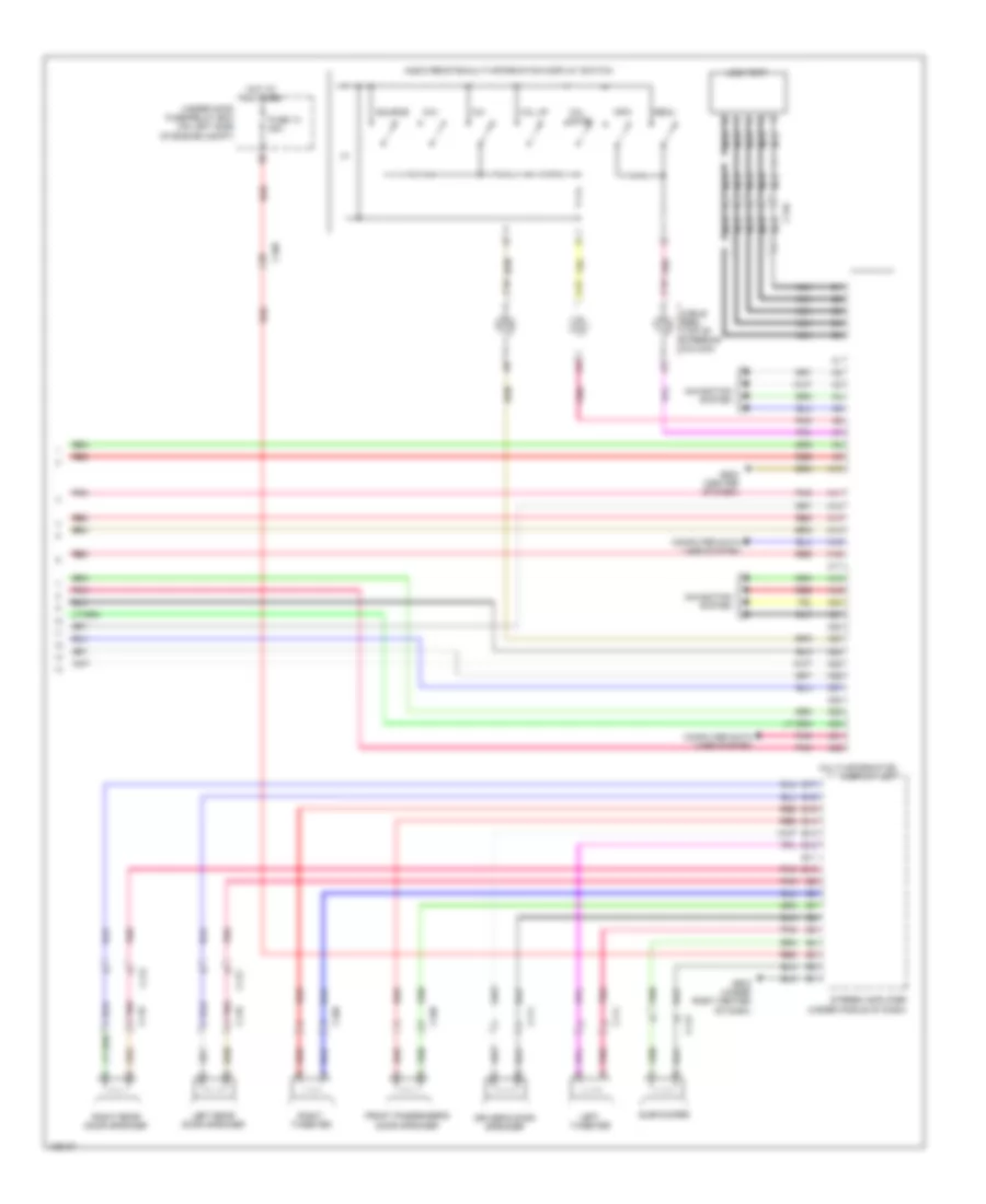
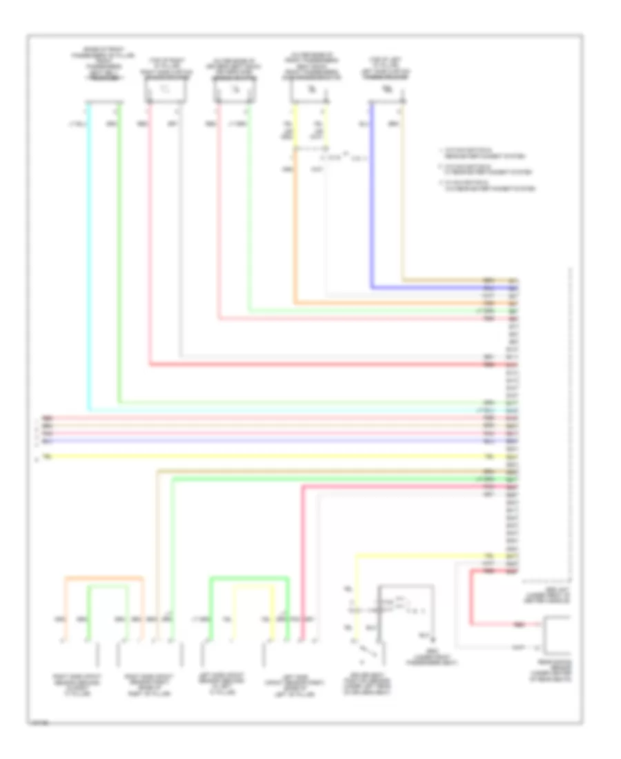
Automatic A/C Wiring Diagram (2 of 3) for Honda CR-V LX 2014
List of elements for Automatic A/C Wiring Diagram (2 of 3) for Honda CR-V LX 2014:
- A/c compressor clutch (a/c compressor clutch/ thermal protector) (lower left front of engine)
- A/c compressor clutch relay (in under-hood fuse/relay box)
- A/c condenser fan relay
- Blower motor (bottom of a/c blower unit)
- Blower motor relay
- C105
- C108
- C133
- C134
- C138
- Diode a
- Diode b
- Driver's j/b 2 (left side of dash)
- Fuse 1-6 100a
- Fuse 10a
- Fuse 15a
- Fuse 2-10 20a
- Fuse 2-11 20a
- Fuse 2-8 40a
- Fuse 20a
- Fuse 7.5a
- G402 (left kick panel)
- Hot at all times
- Humidity sensor
- Humidity/in-car temperature sensor (lower left center of dash)
- In-car temperature sensor
- Outside air temperature sensor (behind left side of front bumper)
- Pnk
- Red
- Under-hood fuse/relay box (on left side of engine compt)
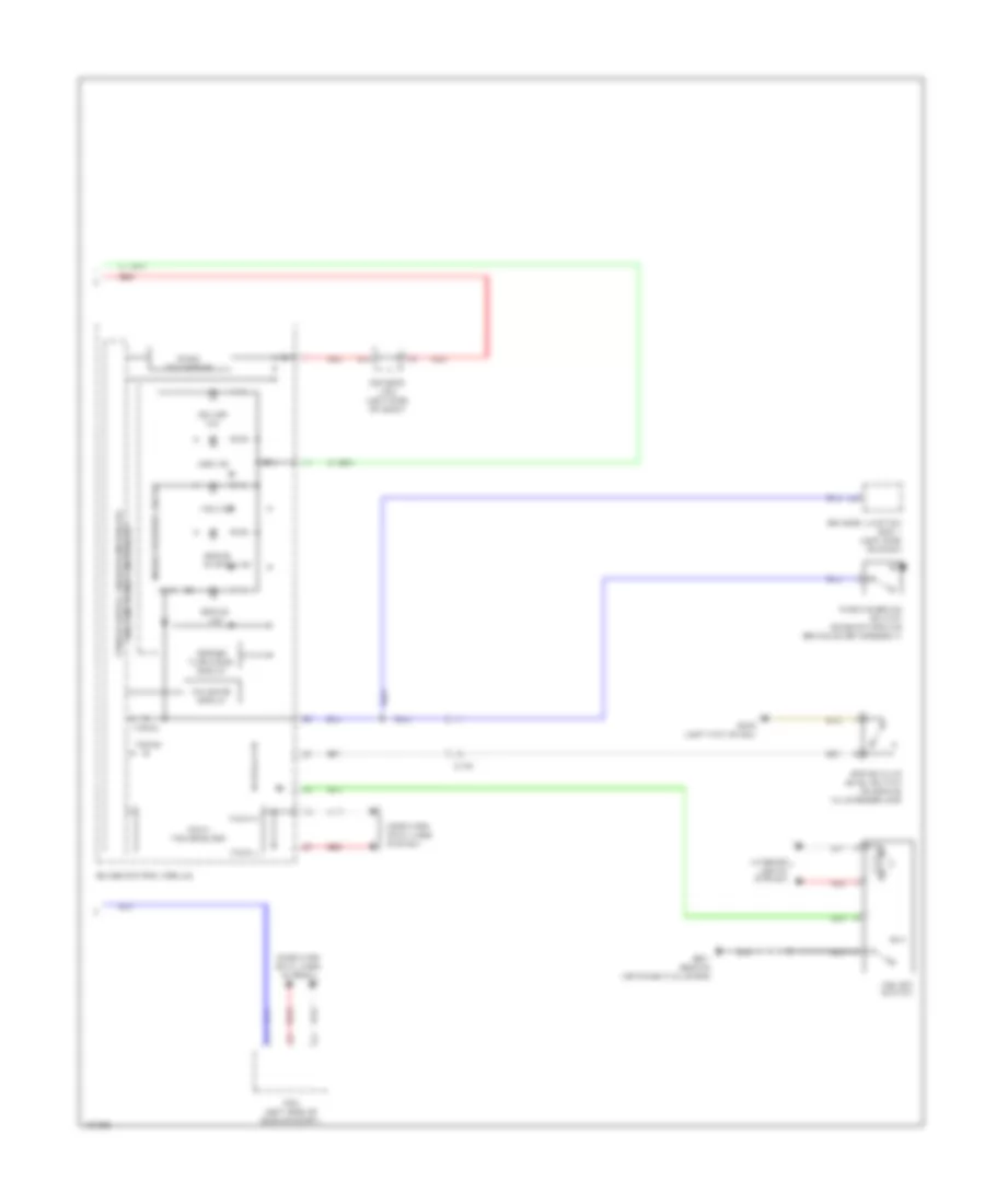
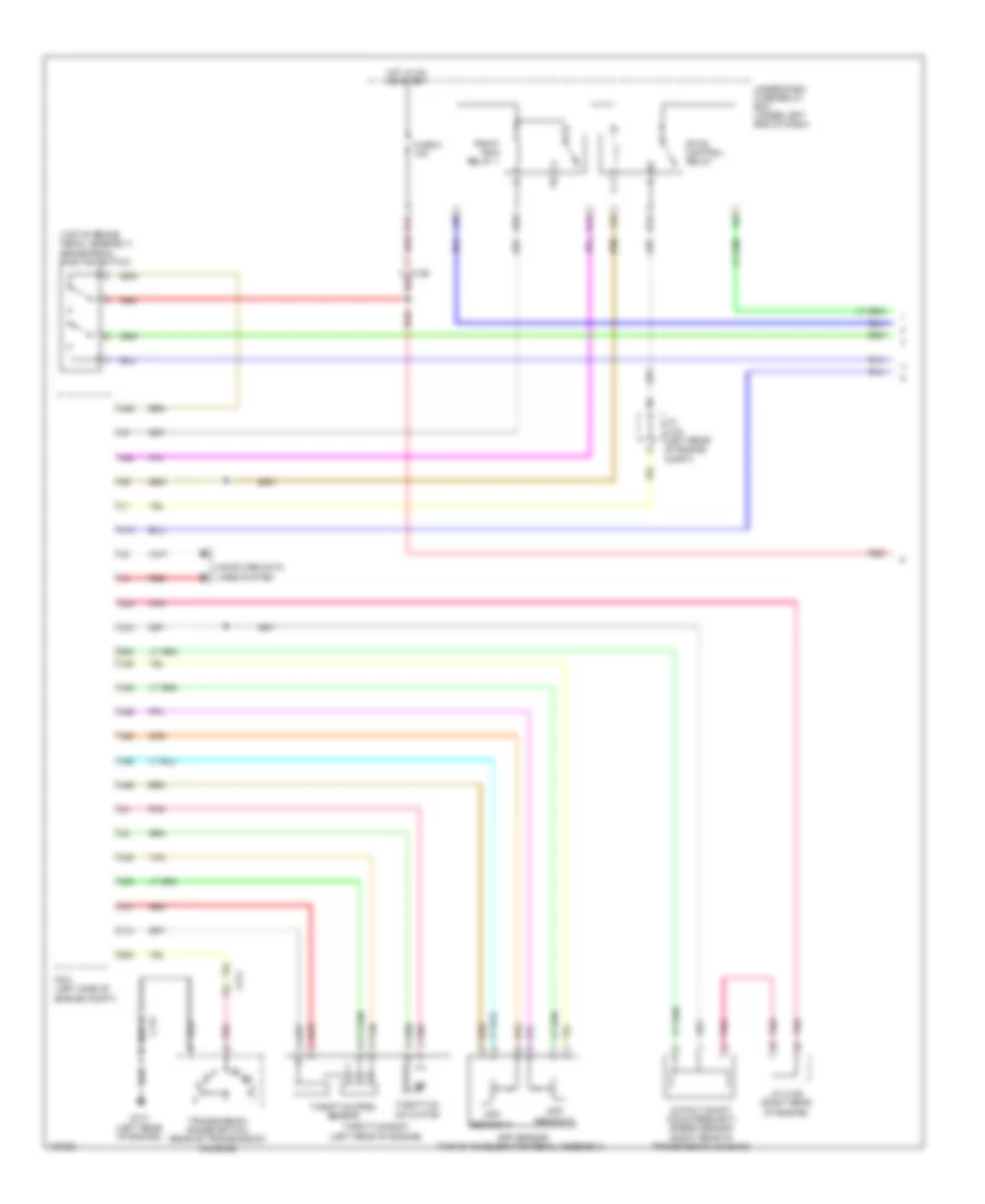
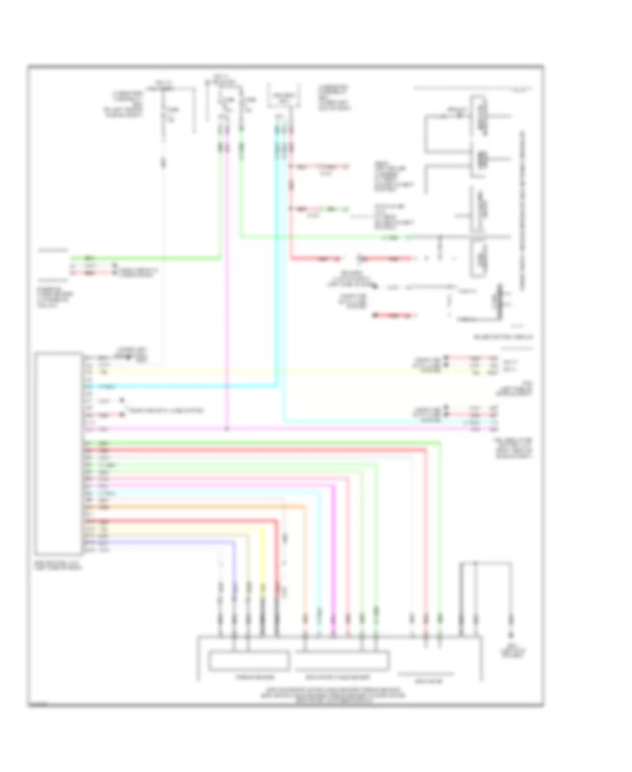
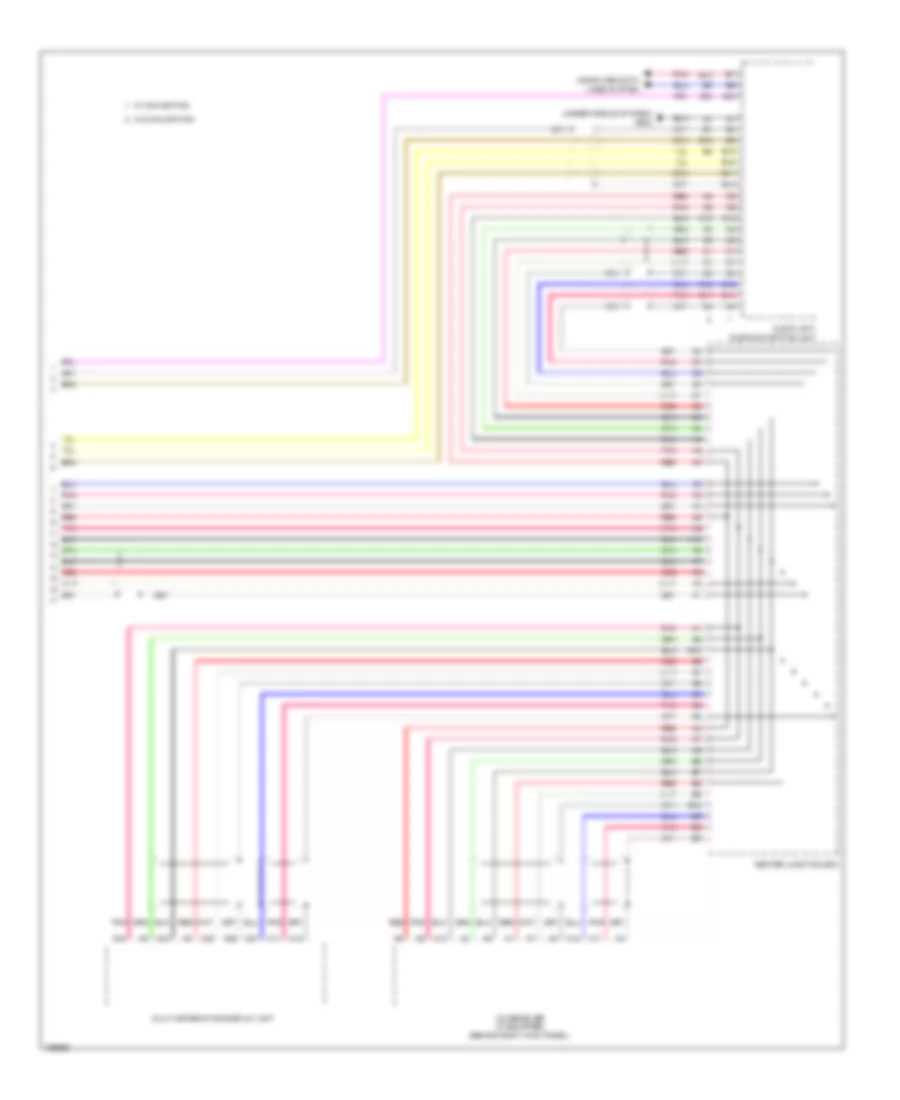
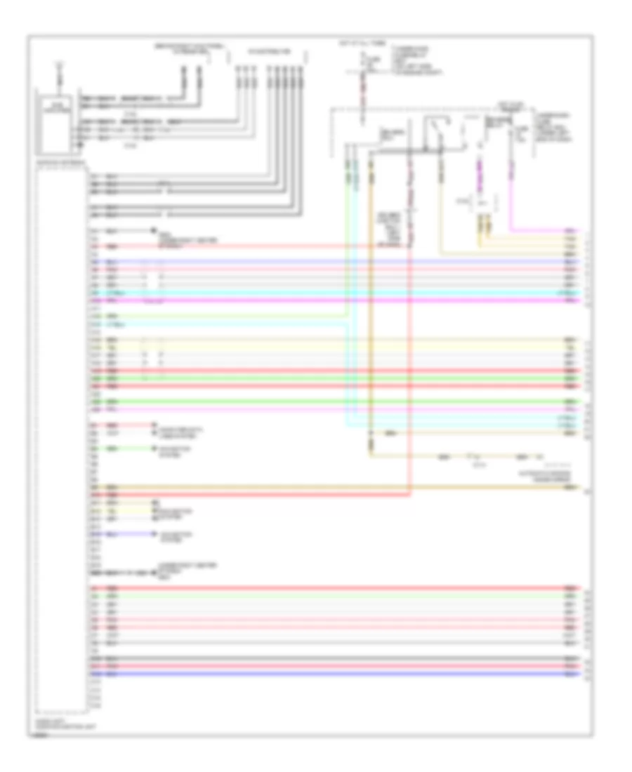
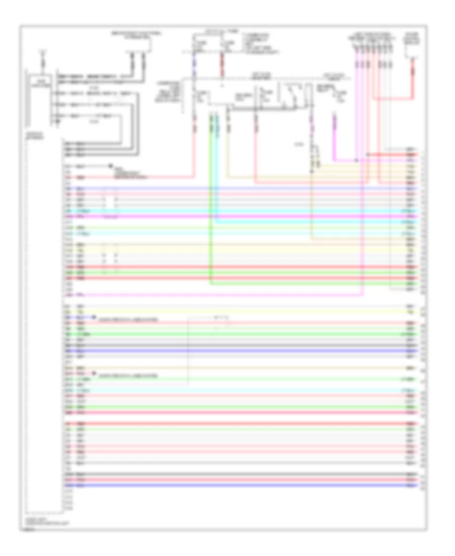
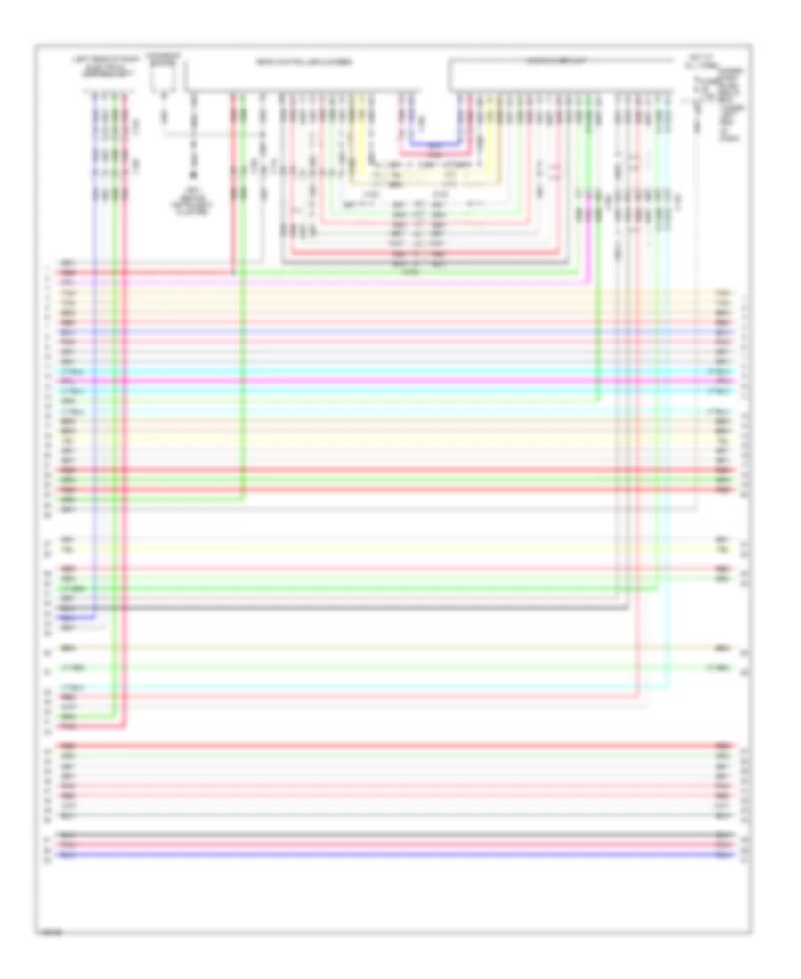
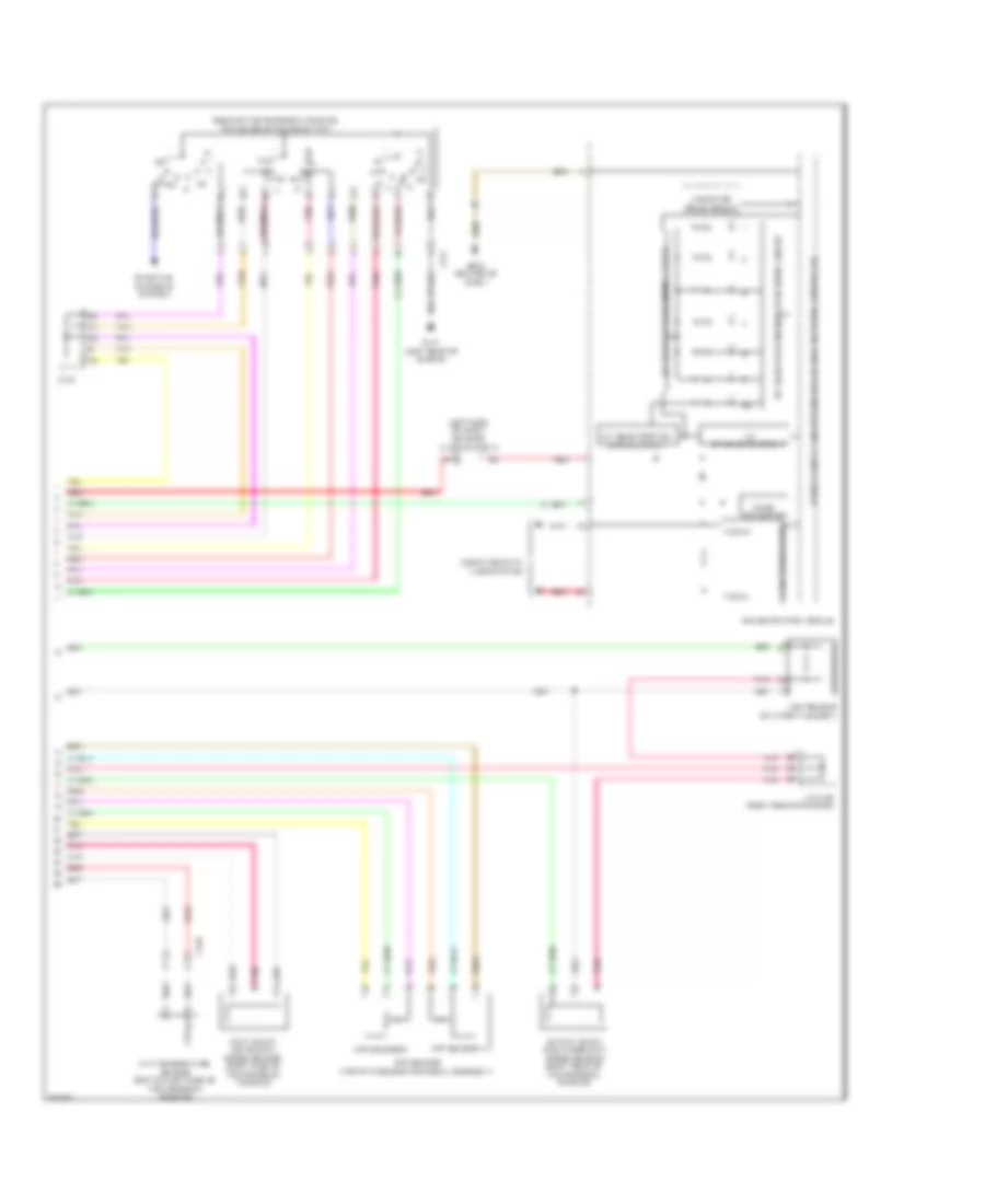
Automatic A/C Wiring Diagram (3 of 3) for Honda CR-V LX 2014
List of elements for Automatic A/C Wiring Diagram (3 of 3) for Honda CR-V LX 2014:
- (behind instrument cluster) g501
- (behind left side of radiator) radiator fan motor
- (behind right side of radiator) a/c condenser fan motor
- (bottom left rear of radiator) ect sensor 2
- (fuel tank) ftp sensor
- (in under-hood fuse/relay box) fan control relay
- (in under-hood fuse/relay box) radiator fan relay
- (left side of engine compt) pcm
- (rear of engine) ect sensor 1
- 10 v stabilizing circuit
- A/c pressure sensor (right front of engine compt)
- A10
- A11
- A12
- A14
- A15
- A16
- A20
- A27
- A30
- A37
- A44
- B-can transceiver
- B34
- B44
- C106
- C126
- C138
- C20
- Computer data lines system
- Dc/dc converter
- Dimming circuit
- Driver's j/b 2 (left side of dash)
- Eco ind
- Econ switch
- F-can transceiver
- G101 (left rear of engine)
- G302 (under left headlight assembly)
- G402 (left kick panel)
- G502 (center of dash)
- Gauge control module
- Illumination controller
- Indicator drive circuit
- Interior lights system
- Multi-information display unit
- Pnk
- Power transistor (near blower motor)
- Red
- Relay circuit board
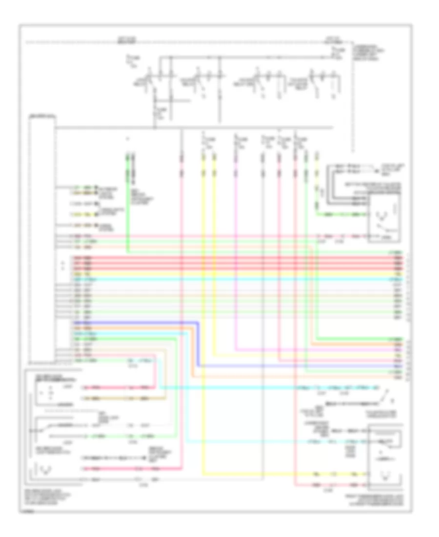
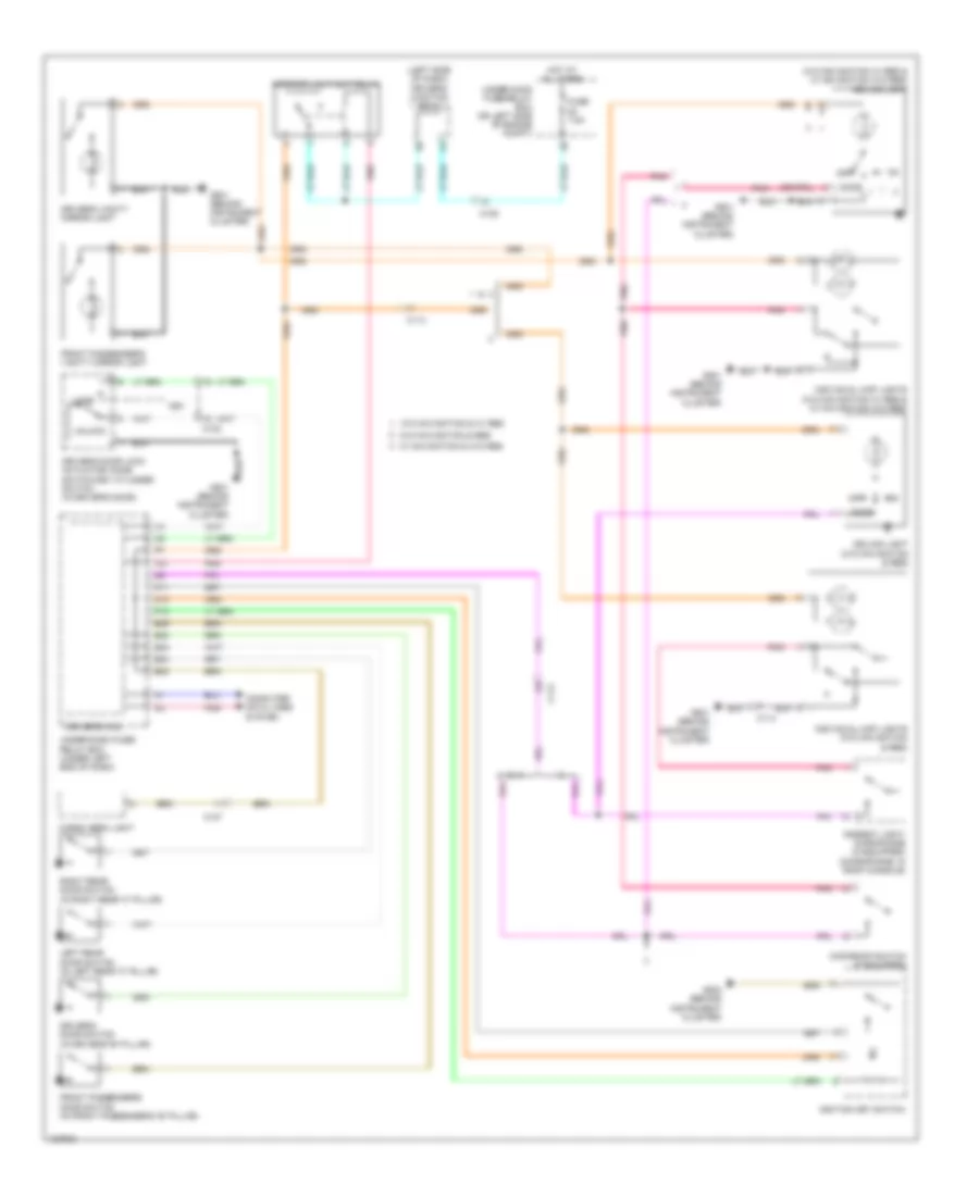
Manual A/C Wiring Diagram (1 of 3) for Honda CR-V LX 2014
List of elements for Manual A/C Wiring Diagram (1 of 3) for Honda CR-V LX 2014:
- 10a
- 7.5a
- C106
- C108
- C12
- C17
- C19
- Computer data lines system
- D17
- D28
- D31
- Driver's air mix control motor (left side of hvac unit)
- Driver's j/b 2 (left side of dash)
- Engine controls system
- Evaporator temperature sensor (on evaporator)
- Fuse
- Fuse 7.5a
- G502 (center of dash)
- Hot in on
- Hot in on or start
- Hvac control unit/ climate control unit
- Micu
- Mode control motor (right side of hvac unit)
- Pgm-fi sub relay
- Pnk
- Q16
- Rear window defogger relay
- Rear window defogger switch/ power mirror defogger switch
- Rear window defogger switch/ power mirror defogger switch indicator (led)
- Recirculation control motor (upper left side of blower unit)
- Red
- Relay circuit board
- Tail light relay
- Under-dash fuse/relay box (under left end of dash)
- Under-hood fuse/relay box (on left side of engine compt)
- W12
Manual A/C Wiring Diagram (2 of 3) for Honda CR-V LX 2014
List of elements for Manual A/C Wiring Diagram (2 of 3) for Honda CR-V LX 2014:
- A/c compressor clutch (a/c compressor clutch/ thermal protector) (lower left front of engine)
- A/c compressor clutch relay (in under-hood fuse/relay box)
- A/c condenser fan relay
- Blower motor (bottom of a/c blower unit)
- Blower motor relay
- C105
- C108
- C133
- C134
- C138
- Diode a
- Diode b
- Driver's j/b 2 (left side of dash)
- Fuse 1-6 100a
- Fuse 10a
- Fuse 15a
- Fuse 2-10 20a
- Fuse 2-11 20a
- Fuse 2-8 40a
- Fuse 20a
- Fuse 7.5a
- G402 (left kick panel)
- Hot at all times
- Outside air temperature sensor (behind left side of front bumper)
- Pnk
- Red
- Under-hood fuse/relay box (on left side of engine compt)
Manual A/C Wiring Diagram (3 of 3) for Honda CR-V LX 2014
List of elements for Manual A/C Wiring Diagram (3 of 3) for Honda CR-V LX 2014:
- (behind instrument cluster) g501
- (behind left side of radiator) radiator fan motor
- (behind right side of radiator) a/c condenser fan motor
- (bottom left rear of radiator) ect sensor 2
- (fuel tank) ftp sensor
- (in under-hood fuse/relay box) fan control relay
- (in under-hood fuse/relay box) radiator fan relay
- (left side of engine compt) pcm
- (rear of engine) ect sensor 1
- 10 v stabilizing circuit
- A/c pressure sensor (right front of engine compt)
- A10
- A11
- A12
- A14
- A15
- A16
- A20
- A27
- A30
- A37
- A44
- B-can transceiver
- B34
- B44
- C106
- C126
- C138
- C20
- Computer data lines system
- Dc/dc converter
- Dimming circuit
- Driver's j/b 2 (left side of dash)
- Eco ind
- Econ switch
- F-can transceiver
- G101 (left rear of engine)
- G302 (under left headlight assembly)
- G402 (left kick panel)
- G502 (center of dash)
- Gauge control module
- Illumination controller
- Indicator drive circuit
- Interior lights system
- Multi-information display unit
- On/off 5v
- Pnk
- Power transistor (near blower motor)
- Red
- Relay circuit board
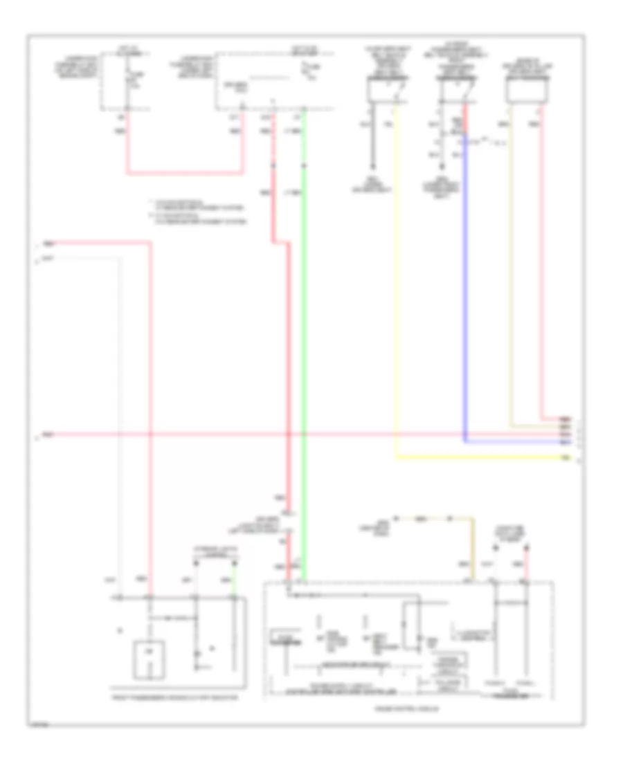
ANTI-LOCK BRAKES
Anti-lock Brakes Wiring Diagram (1 of 2) for Honda CR-V LX 2014
List of elements for Anti-lock Brakes Wiring Diagram (1 of 2) for Honda CR-V LX 2014:
- (behind instrument cluster)
- A11
- Brake pedal position switch (top of brake pedal assembly)
- C120
- C126
- C16
- Computer data lines system
- D11
- D14
- D17
- Driver's micu
- Eps control unit (left side of dash)
- Fuse 1-3 40a
- Fuse 1-4 20a
- Fuse 10a
- Fuse 7.5a
- G201 (right rear of engine compt)
- G501
- Hot at all times
- Hot in on or start
- Left front wheel speed sensor (on left front wheel hub assembly)
- Left rear wheel speed sensor (on left rear wheel hub assembly)
- P15
- Pnk
- Q16
- Red
- Right front wheel speed sensor (on right front wheel hub assembly)
- Right rear wheel speed sensor (on right rear wheel hub assembly)
- Steering angle sensor (in steering column)
- Under-dash fuse/ relay box (under left end of dash)
- Under-hood fuse/relay box (on left side of engine compt)
- Vsa modulator control unit (right rear of engine compt)
- W/ rear entertainment system
- W/o navigation &
Anti-lock Brakes Wiring Diagram (2 of 2) for Honda CR-V LX 2014
List of elements for Anti-lock Brakes Wiring Diagram (2 of 2) for Honda CR-V LX 2014:
- A13
- Abs ind
- Brake fluid level switch (on brake fluid reservoir)
- Brake ind
- Brake system ind
- C108
- Computer data lines system
- Dc/dc converter
- Driver's j/b 2 (left side of dash)
- Driver's junction box 1 (left side of dash)
- F-can h
- F-can l
- F-can transceiver
- Fail-safe circuit
- Forced turning-on circuit
- G402 (left kick panel)
- G501 (behind instrument cluster)
- Gauge control module
- Indicator drive circuit
- Interior lights system
- Parking brake switch (base of parking brake lever assembly)
- Pcm (left side of engine compt)
- Red
- Vsa ind
- Vsa off ind
- Vsa off switch
ANTI-THEFT
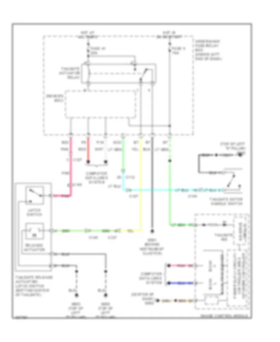
Forced Entry Wiring Diagram (1 of 2) for Honda CR-V LX 2014
List of elements for Forced Entry Wiring Diagram (1 of 2) for Honda CR-V LX 2014:
- (behind instrument cluster) g501
- (bottom center of tailgate) tailgate release actuator/latch switch
- (top of left "d" pillar) g603
- (under right center of dash) g503
- B11
- B16
- B18
- B22
- B29
- B33
- B34
- B40
- C102
- C109
- C11
- C112
- C127
- C14
- C145
- C18
- C27
- D17
- D22
- Door lock knob
- Driver's door key cylinder switch
- Driver's door lock actuator/knob switch/ key cylinder switch (in driver's door)
- Driver's door lock knob switch
- Driver's micu
- Exterior lights system
- Front passenger's door lock actuator/knob switch (in front passenger's door)
- Fuse 10a
- Fuse 15a
- Fuse 20a
- G501 (behind instrument cluster)
- G603 (top of left "d" pillar)
- Headlights system
- Horns system
- Hot at all times
- Hot in on or start
- Key door lock knob
- Lock
- Lock relay
- N10
- N12
- Open
- P11
- Pnk
- Q10
- Q16
- Red
- Tailgate actuator relay
- Tailgate outer handle switch
- Under-dash fuse/relay box (under left end of dash)
- Unlock
- Unlock relay
- Unlock relay (dr)
- W10
- W23
- X10
Forced Entry Wiring Diagram (2 of 2) for Honda CR-V LX 2014
List of elements for Forced Entry Wiring Diagram (2 of 2) for Honda CR-V LX 2014:
- (center front of engine compt) (except lx) security hood switch
- (rear of transmission housing) transmission range switch
- 10v
- Antenna
- B-can h
- B-can l
- B-can transceiver
- C102
- C109
- C112
- C113
- C118
- C119
- C131
- Circuit
- Circuit stabilizing
- Close
- Computer data lines system
- Dc/dc converter
- Dlc (under left center of dash)
- Door ind
- Door lock knob
- Driver's door switch (in driver's "b" pillar)
- Driver's junction box 1 (left side of dash)
- Driver's junction box 2 (left side of dash)
- Exl w/o navigation & w/ res
- Front passenger's door switch (in front passenger's "b" pillar)
- Front passenger's power window switch
- Fuse 10a
- G101 (left rear of engine)
- G402 (left kick panel)
- G501 (behind instrument cluster)
- G502 (center of dash)
- G503 (under right center of dash)
- G601 (under driver's seat)
- G604 (right "d" pillar)
- Gauge control module
- Hot at all times
- Ignition key switch
- Immobilizer keyless control unit (on steering column, integral to ignition switch)
- Indicator drive
- J/c c134 (left rear of engine compt)
- Left rear door lock actuator/knob switch (in left rear door)
- Left rear door switch (in left rear "c" pillar)
- Lock
- Network controller
- Pnk
- Power window master switch
- R p
- Red
- Right rear door lock actuator/knob switch (in right rear door)
- Right rear door switch (in right rear "c" pillar)
- Security ind
- Sound systems
- Tailgate ind
- Under-hood fuse/relay box (on left side of engine compt)
- Unlock
Immobilizer Wiring Diagram for Honda CR-V LX 2014
List of elements for Immobilizer Wiring Diagram for Honda CR-V LX 2014:
- (left rear of engine compt) j/c c134
- (left side of dash) driver's junction box 2
- A17
- A40
- Antenna
- B-can h
- B-can l
- B10
- C10
- C108
- C13
- C15
- C24
- C35
- Computer data lines system
- D17
- D26
- Dc/dc converter
- Driver's junction box 1 (left side of dash)
- Driver's micu
- Exl w/o navigatiom & w/ res
- F-can h
- F-can l
- Fuel tank unit (top of fuel tank)
- Fuse 10a
- Fuse 15a
- G101 (left rear of engine)
- G502 (center of dash)
- G603 (top of left "d" pillar)
- Gauge control module
- Hot at all times
- Hot in on or start
- Ignition key switch
- Immobilizer ind
- Immobilizer keyless control unit (on steering column, integral to ignition switch)
- P11
- P18
- Parking brake switch (base of parking brake lever assembly)
- Pcm (left side of engine compt)
- Pgm-fi main relay 1
- Pgm-fi main relay 2
- Pnk
- Q16
- Red
- Transceiver b-can
- Transceiver f-can
- Under-dash fuse/relay box (under left end of dash)
- Under-hood fuse/relay box (on left side of engine compt)
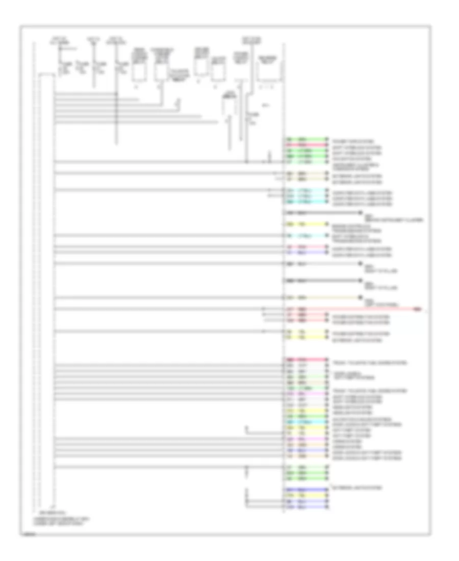
BODY CONTROL MODULES
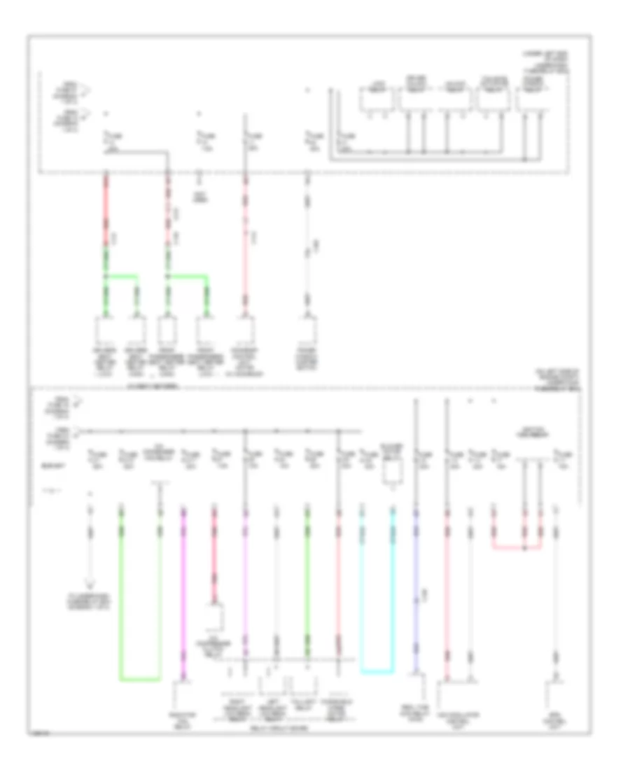
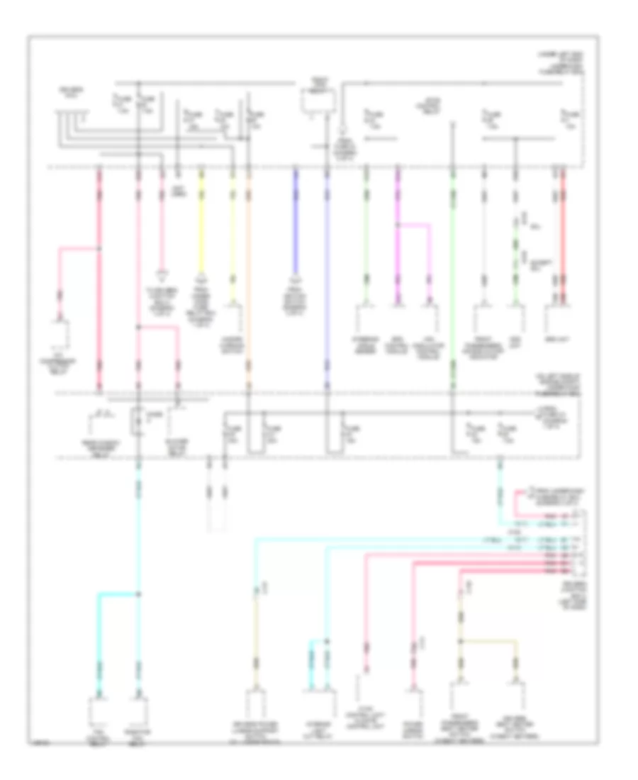
Body Control Modules Wiring Diagram (1 of 2) for Honda CR-V LX 2014
List of elements for Body Control Modules Wiring Diagram (1 of 2) for Honda CR-V LX 2014:
- Anti-theft system
- B12
- B20
- B21
- B22
- B28
- B29
- B32
- B33
- B34
- B40
- C14
- C16
- C18
- C24
- C27
- C37
- Computer data lines system
- D10
- D11
- D15
- D17
- D22
- D24
- Door locks & anti-theft systems
- Driver unlock relay
- Driver's micu
- Engine controls & transmissions systems
- Exterior lights system
- Fuse 10a
- Fuse 20a
- Fuse 7.5a
- G402 (left kick panel)
- G501 (behind instrument cluster)
- G604 (right "d" pillar)
- Headlights system
- Horns system
- Hot at all times
- Hot in on
- Hot in on or acc
- Hot in on or start
- Instrument cluster & warning systems
- Lock relay
- Navigation & sound systems
- Navigation system
- P10
- P11
- P19
- Pnk
- Power distribution system
- Power tops system
- Power window relay
- Q10
- Q14
- Q16
- Rear window washer relay
- Red
- Reverse relay
- Shift interlock & transmissions systems
- Shift interlock system
- Tailgate actuator relay
- Trunk, tailgate, fuel doors system
- Under-dash fuse/relay box (under left end of dash)
- Unlock relay
- W23
- Windshield washer motor relay
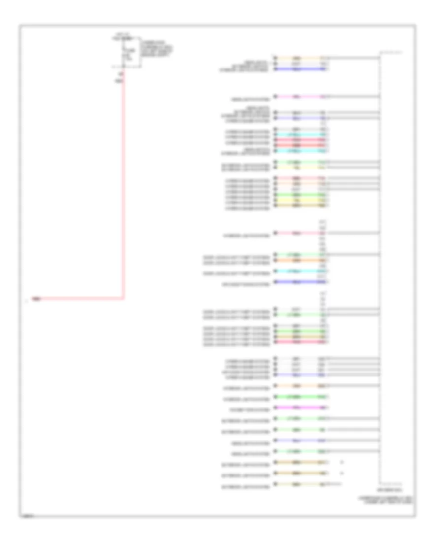
Body Control Modules Wiring Diagram (2 of 2) for Honda CR-V LX 2014
List of elements for Body Control Modules Wiring Diagram (2 of 2) for Honda CR-V LX 2014:
- Air conditioning system
- B39
- C11
- C19
- C22
- C23
- C32
- D16
- D25
- D31
- Door locks & anti-theft systems
- Driver's micu
- Exterior lights system
- Exterior lights system exterior lights system
- Fuse 10a
- Headlights & interior lights systems
- Headlights system
- Headlights, exterior lights & interior lights systems
- Hot at all times
- Interior lights system
- P12
- Pnk
- Power tops system
- Red
- T10
- T11
- T12
- T13
- T14
- T15
- T16
- T17
- T18
- T19
- T20
- Under-dash fuse/relay box (under left end of dash)
- Under-hood fuse/relay box (on left side of engine compt)
- W10
- W11
- W12
- Wiper/washer system
- X10
COMPUTER DATA LINES
Computer Data Lines Wiring Diagram (1 of 2) for Honda CR-V LX 2014
List of elements for Computer Data Lines Wiring Diagram (1 of 2) for Honda CR-V LX 2014:
- (behind left rear quarterpanel) (awd) real time awd control unit
- (behind left rear quarterpanel) j/c c128
- A17
- A42
- B42
- B43
- C105
- C126
- C134
- C20
- C24
- D15
- D17
- D18
- D19
- D24
- Dlc (under left center of dash)
- Driver's junction box 1 (left side of dash)
- Driver's micu
- Eps control unit (left side of dash)
- Except lx
- Fuse 29 10a
- G101 (left rear of engine)
- G501 (behind instrument cluster)
- G502 (center of dash)
- Hot at all times
- J/c c141 (left kick panel)
- P16
- Pcm (left side of engine compt)
- Q14
- Red
- Steering angle sensor (in steering column)
- Under-dash fuse/relay box (under left side of dash)
- Under-hood fuse/relay box (on left side of engine compt)
- Vsa modulator control unit (right rear of engine compt)
Computer Data Lines Wiring Diagram (2 of 2) for Honda CR-V LX 2014
List of elements for Computer Data Lines Wiring Diagram (2 of 2) for Honda CR-V LX 2014:
- (left side of dash) driver's junction box 1
- (top center of dash) (if equipped) automatic lighting/ sunlight sensor
- A13
- A15
- A19
- A20
- A21
- A31
- Audio unit/ audio navigation unit
- B13
- Driver's junction box 2 (left side of dash)
- Driver's micu
- Gauge control module
- Hvac control unit/ climate control unit (if equipped)
- Immobilizer keyless control unit (on steering column, integral to ignition switch)
- Multi-information display unit
- Pnk
- Red
- Srs unit (under front of center console)
- Under-dash fuse/relay box (under left side of dash)
- W/ navigation
- W/o navigation
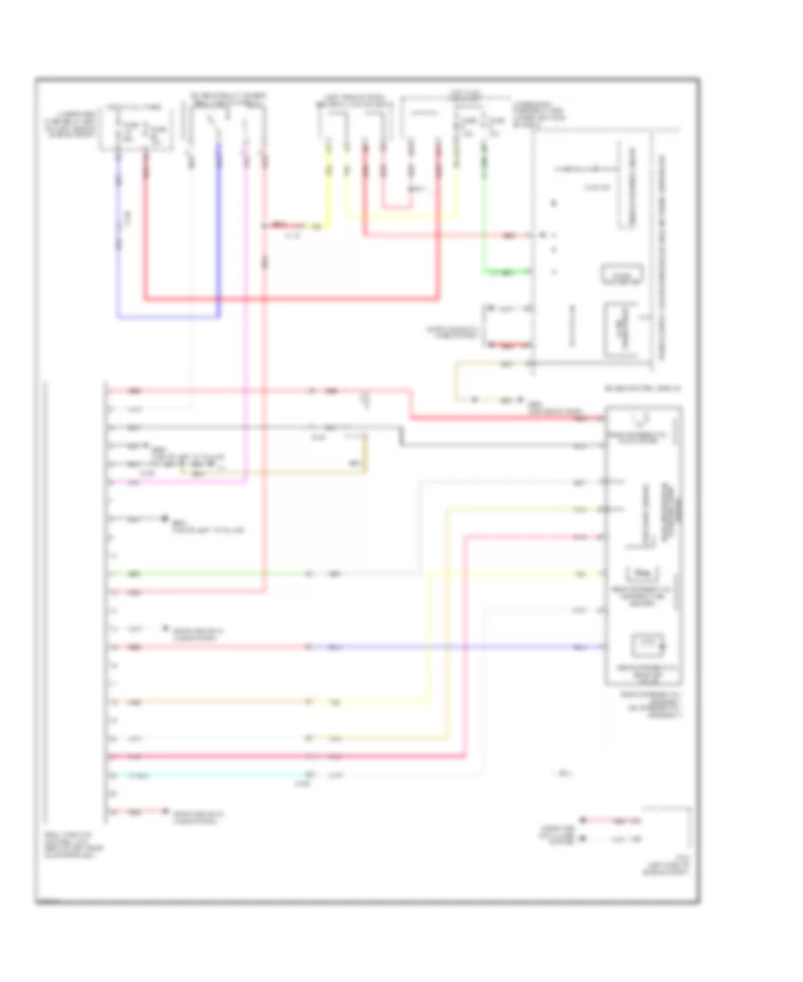
COOLING FAN
Cooling Fan Wiring Diagram for Honda CR-V LX 2014
List of elements for Cooling Fan Wiring Diagram for Honda CR-V LX 2014:
- A/c condenser fan motor (behind right side of radiator)
- A/c condenser fan relay
- A/c pressure sensor (right front of engine compt)
- A11
- A14
- A15
- A16
- A27
- A30
- A44
- B-can transceiver
- B34
- B44
- C20
- Computer data lines system
- D28
- Diode a
- Diode b
- Ect sensor 1 (rear of engine)
- Ect sensor 2 (bottom left rear of radiator)
- F-can transceiver
- Fan control relay (in under-hood fuse/relay box)
- Fuse 2-10 20a
- Fuse 2-11 20a
- Fuse 7.5a
- G101 (left rear of engine)
- G302 (under left headlight assembly)
- Gauge control module
- Hot at all times
- Hot in on
- Hot w/ pgm-fi sub relay energized
- Pcm (left side of engine compt)
- Pnk
- Radiator fan motor (behind left side of radiator)
- Radiator fan relay (in under-hood fuse/relay box)
- Red
- Relay circuit board
- Under-dash fuse/ relay box (under left end of dash)
- Under-hood fuse/relay box (on left side of engine compt)
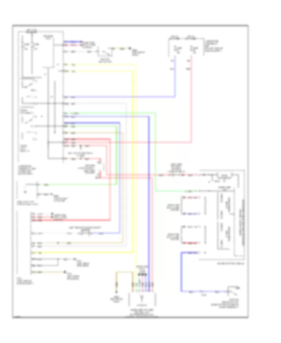
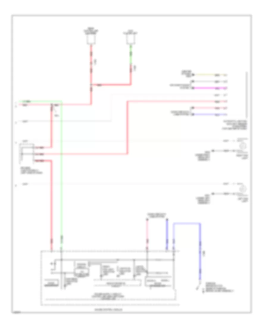
CRUISE CONTROL
Cruise Control Wiring Diagram (1 of 2) for Honda CR-V LX 2014
List of elements for Cruise Control Wiring Diagram (1 of 2) for Honda CR-V LX 2014:
- (top of brake pedal assembly) brake pedal position switch
- A13
- A25
- A28
- A29
- A35
- A36
- A45
- A46
- A48
- App sensor (top of accelerator pedal assembly)
- App sensor a
- App sensor b
- B17
- B35
- B48
- C126 red
- C131
- C14
- C22
- C23
- C24
- C30
- C31
- C34
- Computer data lines system
- D12
- D26
- Etcs control relay
- Fuse 2 10a
- G101 (left rear of engine)
- Hot in on or start
- J/c c134 (left rear of engine compt)
- J/c c136 (right rear of engine)
- Output shaft (countershaft) speed sensor (right rear of transmission housing)
- Pcm (left side of engine compt)
- Pgm-fi main relay 1
- Pnk
- Red
- Tan
- Throttle actuator
- Throttle body (left rear of engine)
- Throttle open sensor
- Transmission range switch (rear of transmission housing)
- Under-dash fuse/relay box (under left end of dash)
Cruise Control Wiring Diagram (2 of 2) for Honda CR-V LX 2014
List of elements for Cruise Control Wiring Diagram (2 of 2) for Honda CR-V LX 2014:
- 10v stabilizing circuit
- Air conditioning system
- C15
- C16
- Cable reel (top of steering column)
- Cancel switch
- Computer data lines system
- Cruise control combination switch
- Cruise control indicator
- Cruise main indicator
- D11
- D17
- Dc/dc converter
- Dimming circuit
- Driver's junction box 2 (left side of dash)
- Driver's micu
- Eld
- F-can h
- F-can l
- F-can transceiver
- Fuse 10a
- Fuse 15a
- G502 (center of dash)
- Gauge control module
- Hot at all times
- Hot in on or start
- Indicator driver circuit
- Interior lights system
- Main switch
- On/ off 5v
- Q16
- Red
- Resume switch
- Set switch
- Under-dash fuse/relay box (under left end of dash)
- Under-hood fuse/relay box (on left side of engine compt)
- W/o navigation & w/ rear entertainment system
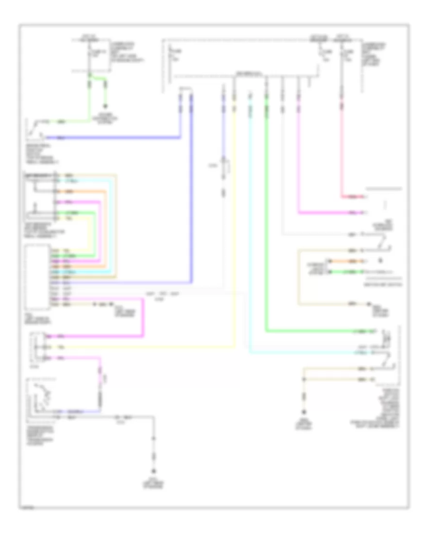
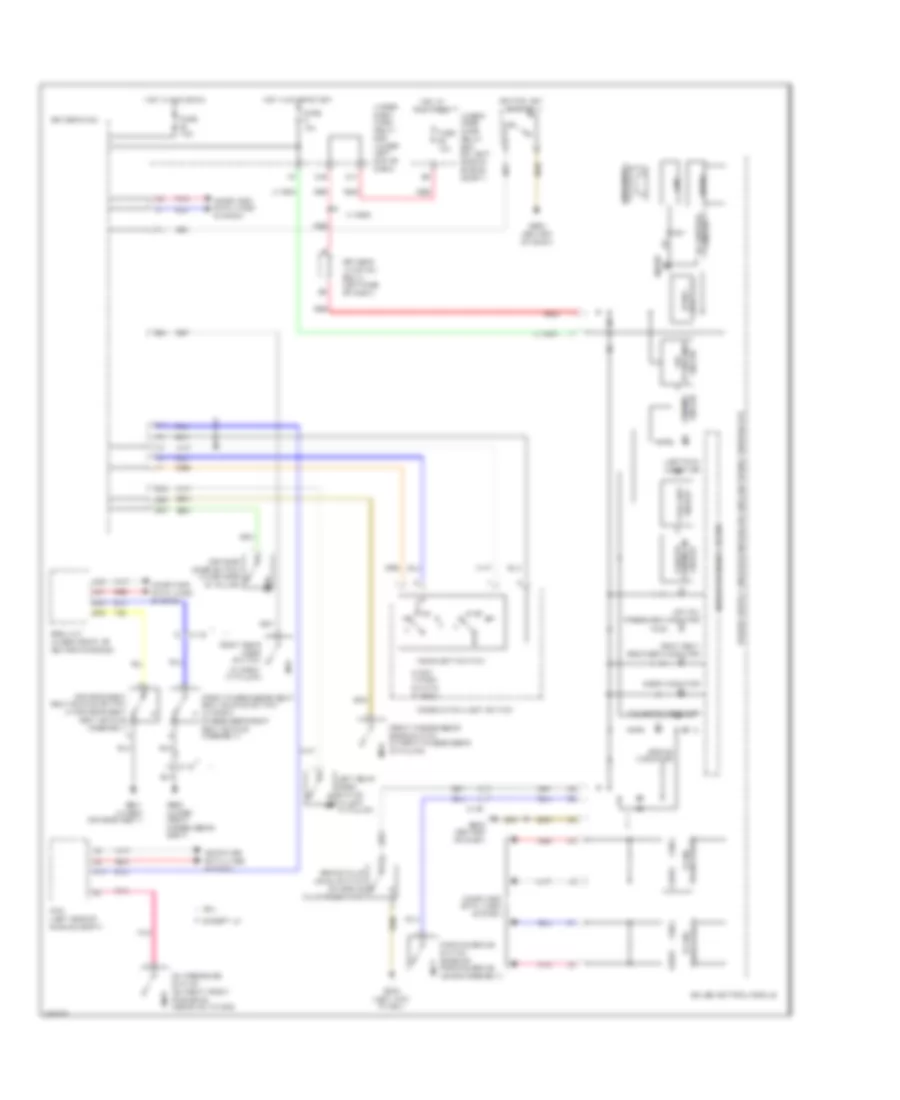
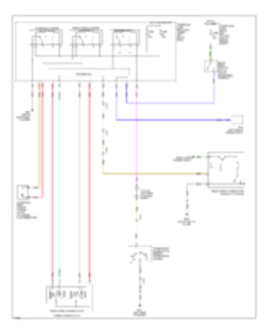
DEFOGGERS
Defoggers Wiring Diagram for Honda CR-V LX 2014
List of elements for Defoggers Wiring Diagram for Honda CR-V LX 2014:
- Automatic a/c
- C108
- C109
- C111
- C126
- C127
- C144
- C17
- Driver's junction box 2 (left side of dash)
- Fuse 2-6 30a
- Fuse 22 7.5a
- Fuse 7.5a
- G501 (behind instrument cluster)
- G502 (center of dash)
- G503 (under right center of dash)
- G603 (top of left "d" pillar)
- Hot at all times
- Hot in on
- Hvac control unit/ climate control unit
- Left power mirror (in driver's door)
- Manual a/c
- Pnk
- Rear window defogger
- Rear window defogger relay
- Rear window/ power mirror defogger switch
- Rear window/ power mirror switch indicator (led)
- Red
- Right power mirror (in front passenger's door)
- Under-dash fuse/relay box (under left end of dash)
- Under-hood fuse/relay box (on left side of engine compt)
- W/ power mirror defogger
- W/o power mirror defogger
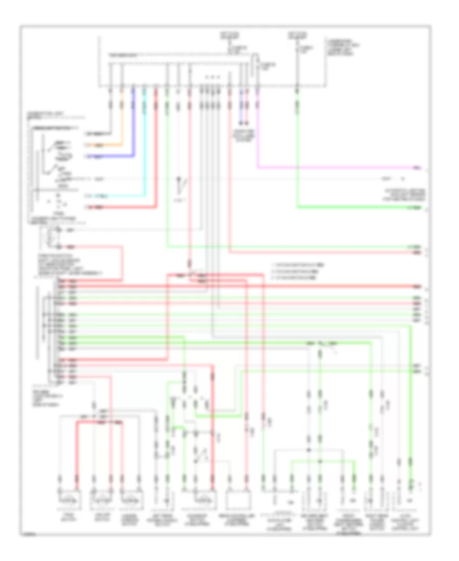
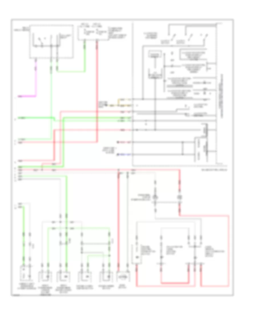
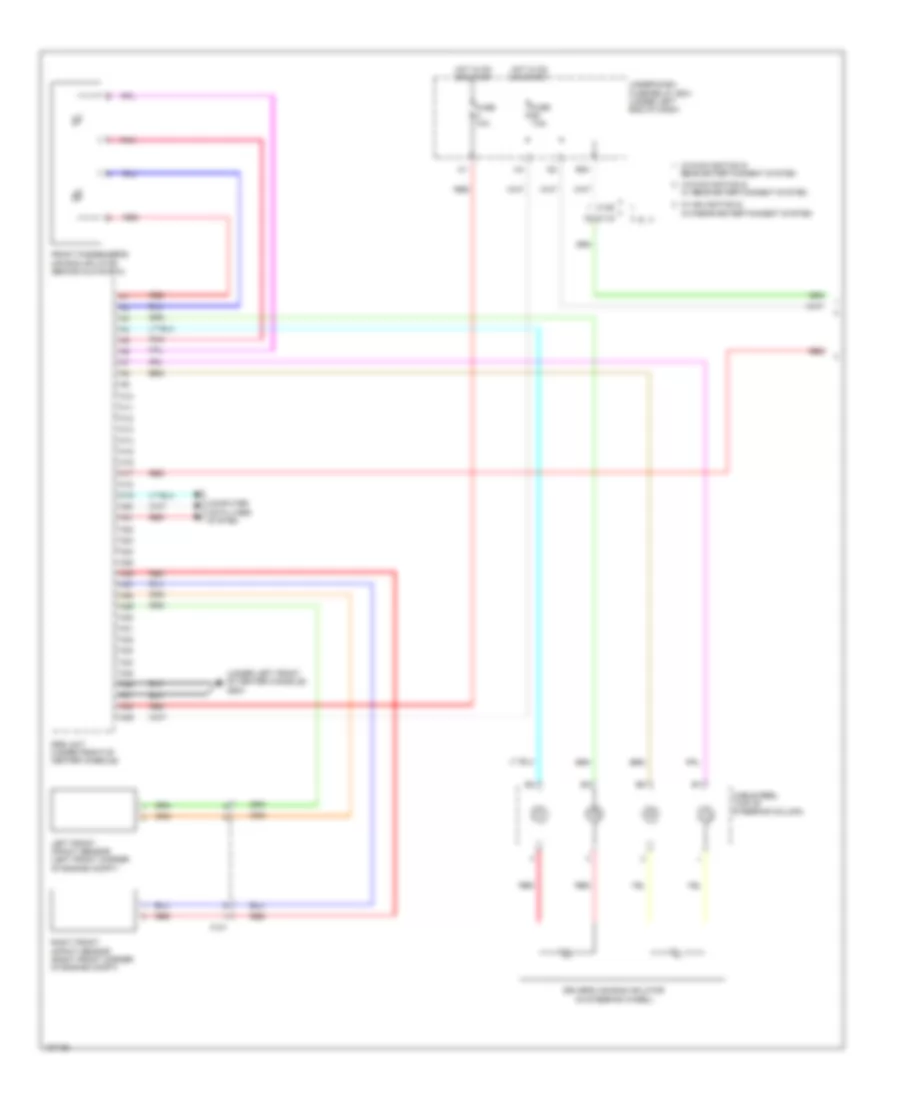
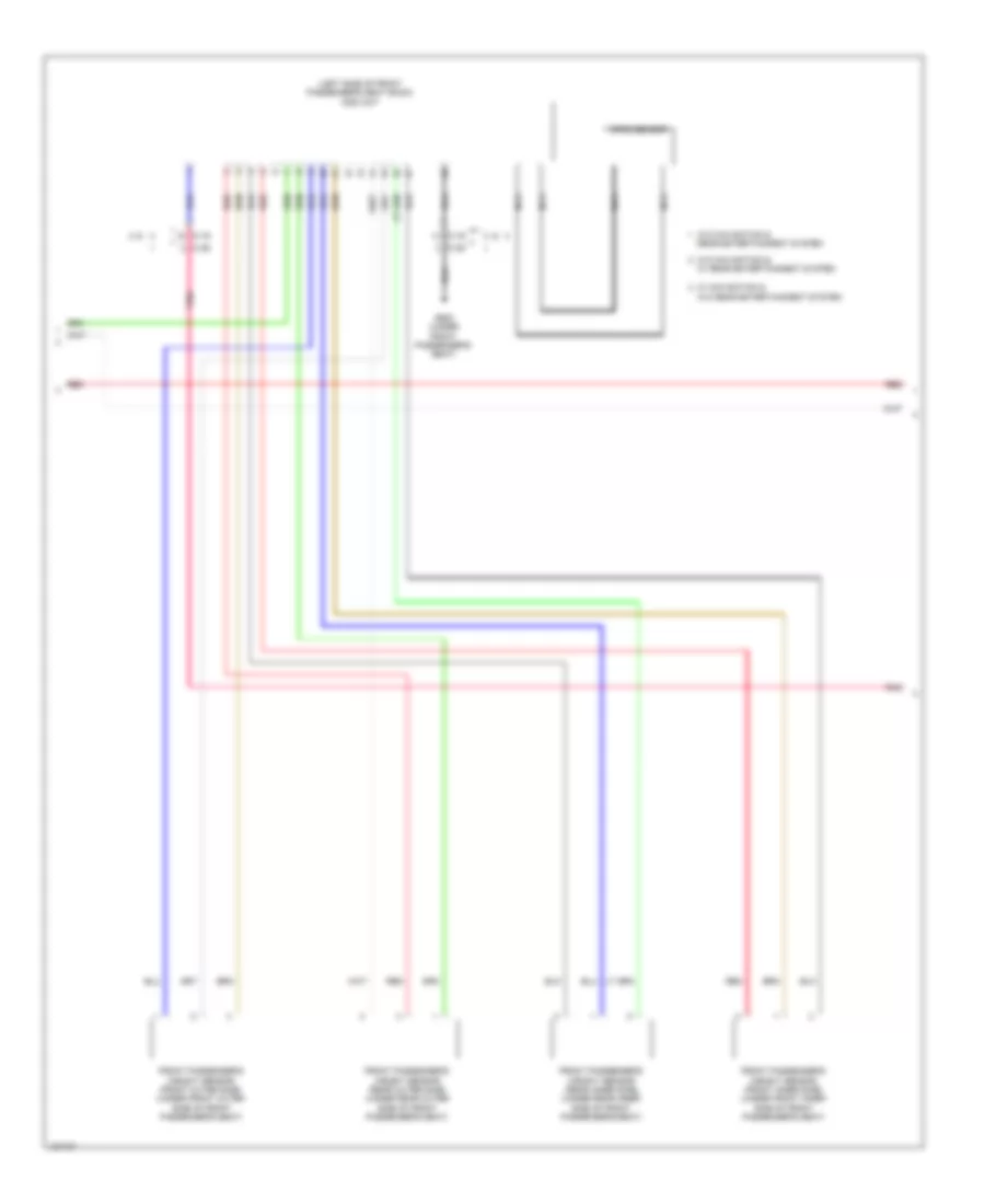
ELECTRONIC POWER STEERING
Electronic Power Steering Wiring Diagram for Honda CR-V LX 2014
List of elements for Electronic Power Steering Wiring Diagram for Honda CR-V LX 2014:
- (in steering column)
- (upper left end of dash) g403
- A10
- A11
- A22
- All times
- B10
- B11
- B12
- B13
- B14
- B15
- B16
- C103
- C104
- C140
- Can h
- Can l
- Circuit 10 v stablizing
- Circuit dimming
- Computer data lines system
- Converter dc/dc
- D14
- D15
- D24
- Driver circuit indicator
- Driver's junction box 2 (left side of dash)
- Driver's micu
- Dvd player unit (w/ rear entertainment system)
- Eps control unit (left side of dash)
- Eps ind
- Eps motor
- Eps motor angle sensor
- Eps motor/eps motor angle sensor/torque sensor (eps motor angle sensor/torque sensor: on eps motor) (eps motor: on steering rack)
- F-can h
- F-can l
- Fuse 1-1 70a
- Fuse 10a
- Fuse 7.5a
- G401 (left end of dash)
- Gauge control module
- Hot at
- Hot in on or start
- Nca
- P15
- Pcm (left side of engine compt)
- Pnk
- Q16
- Rear controller & screen (w/ rear entertainment system)
- Red
- Steering angle sensor
- Torque sensor
- Transceiver f-can
- Under-dash fuse/relay box (under left end of dash)
- Under-hood fuse/relay box (on left side of engine compt)
- Vsa modulator control unit (right rear of engine compt)
ENGINE PERFORMANCE
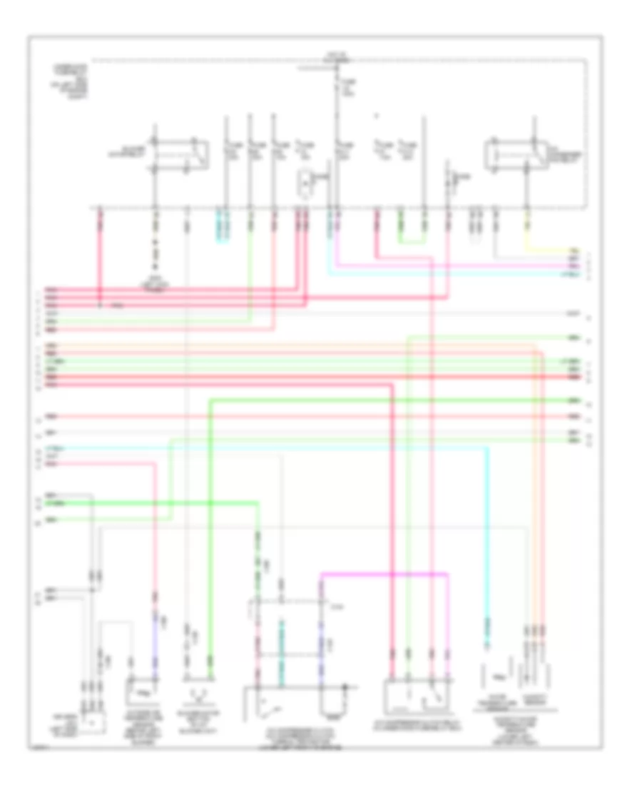
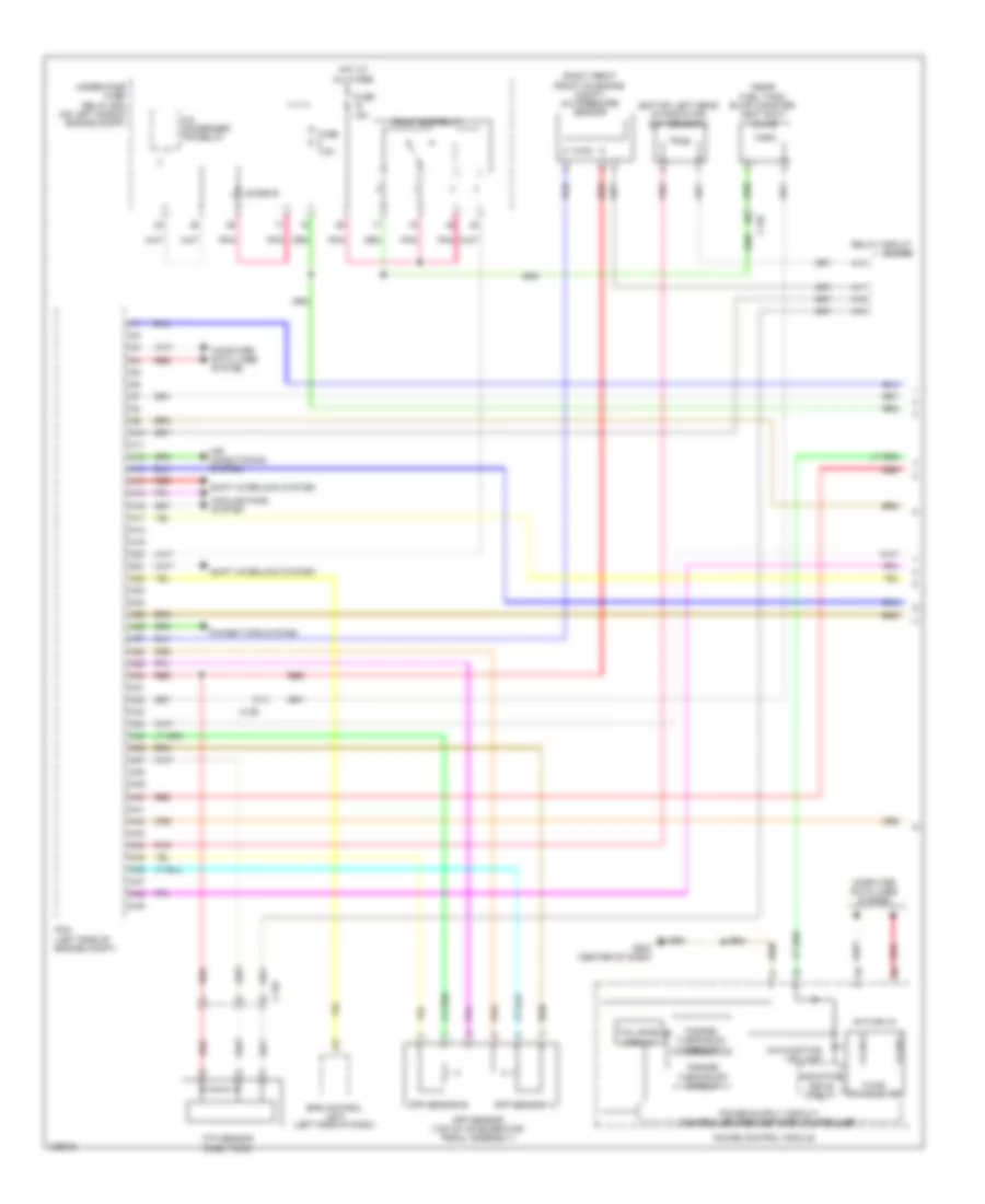
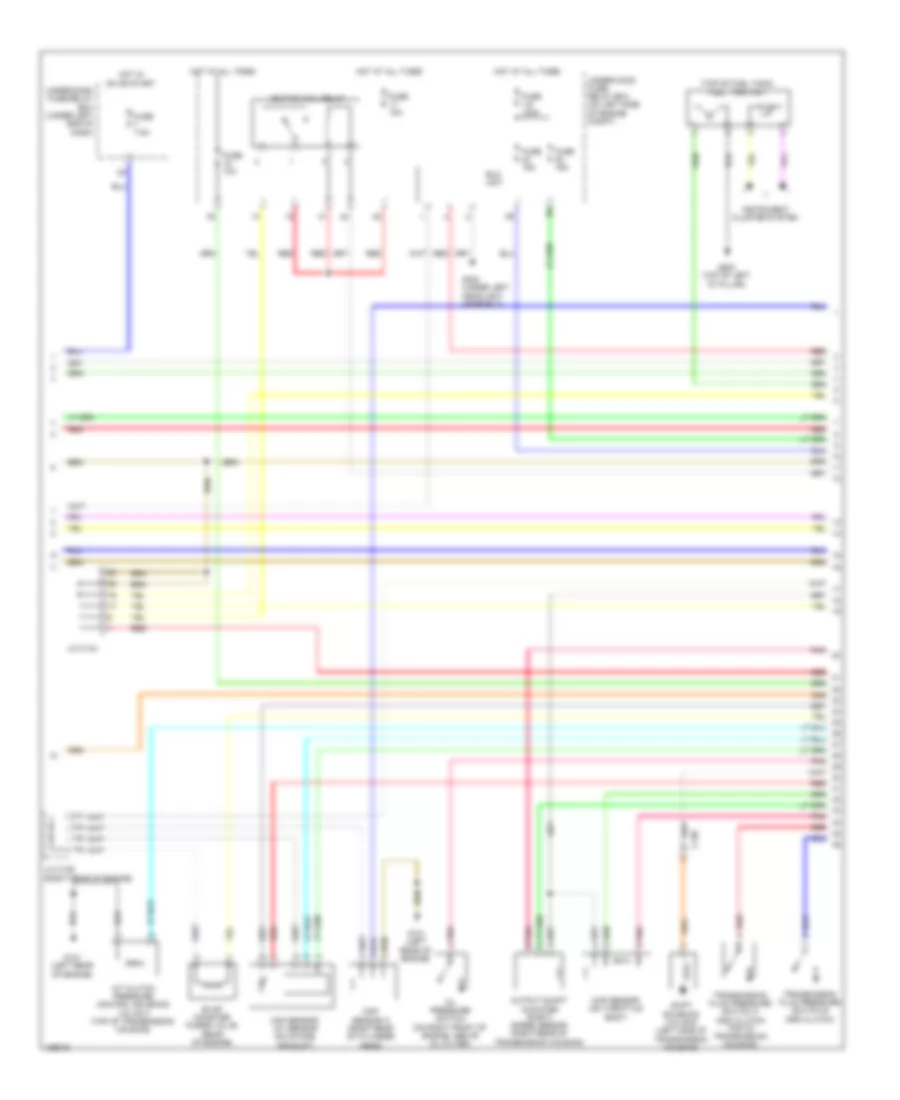
2.4L
2.4L, Engine Performance Wiring Diagram (1 of 5) for Honda CR-V LX 2014
List of elements for 2.4L, Engine Performance Wiring Diagram (1 of 5) for Honda CR-V LX 2014:
- (bottom left rear of radiator) ect sensor 2
- (near fuel tank) evap canister vent shut valve
- (right front front of engine compt) a/c pressure sensor
- A/c condenser fan relay
- A10
- A11
- A12
- A13
- A14
- A15
- A16
- A17
- A18
- A19
- A20
- A21
- A22
- A23
- A24
- A25
- A26
- A27
- A28
- A29
- A30
- A31
- A32
- A33
- A34
- A35
- A36
- A37
- A38
- A39
- A40
- A41
- A42
- A43
- A44
- A45
- A46
- A47
- A48
- A49
- Air conditioning system
- App sensor (top of accelerator pedal assembly)
- App sensor a
- App sensor b
- C126
- Computer data lines system
- Cooling fans system
- Diode b
- Eps control unit (left side of dash)
- F-can h
- F-can l
- F-can transceiver
- Fail-safe circuit
- Forced turning-off circuit
- Forced turning-on circuit
- Ftp sensor (fuel tank)
- Fuse 15a
- Fuse 7.5a
- G502 (center of dash)
- Gauge control module
- Hot at all times
- Indicator drive circuit
- Malfunction ind lamp
- Pcm (left side of engine compt)
- Pgm-fi sub-relay
- Pnk
- Power tops system
- Red
- Relay circuit board
- Shift interlock system
- Under-hood fuse/ relay box (on left side of engine compt)
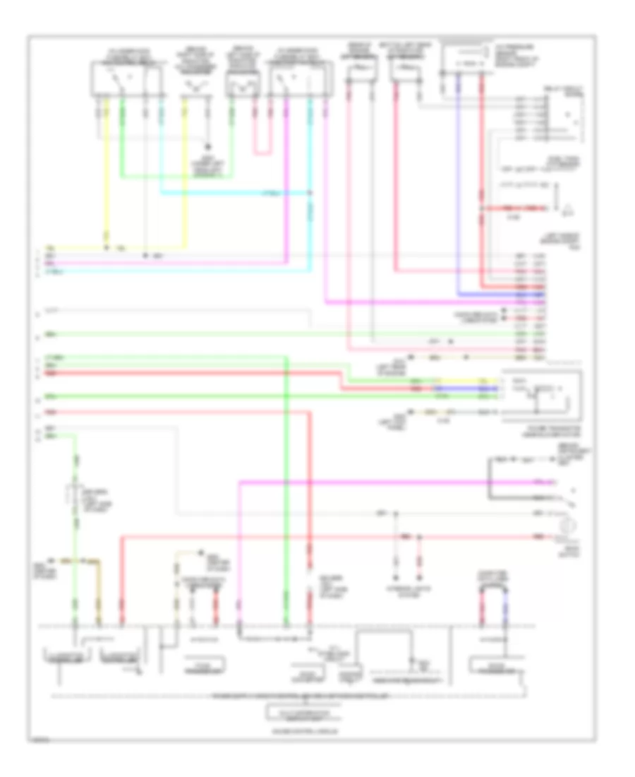
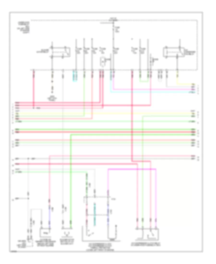
2.4L, Engine Performance Wiring Diagram (2 of 5) for Honda CR-V LX 2014
List of elements for 2.4L, Engine Performance Wiring Diagram (2 of 5) for Honda CR-V LX 2014:
- (top of fuel tank) fuel tank unit
- A/t clutch pressure control solenoid valve a (top of transmission housing)
- C130
- Cmp sensor a (right rear of cylinder head)
- Eld unit
- Evap canister purge valve (rear of engine)
- Fuse 1-6 100a
- Fuse 10a
- Fuse 15a
- Fuse 7.5a
- G101 (left rear of engine)
- G302 (under left headlight assembly)
- G603 (top of left "d" pillar)
- Hot at all times
- Hot in on or start
- Ignition coil relay
- Instrument cluster system
- J/c c134
- J/c c136 (right rear of engine)
- Maf sensor/ iat sensor (on intake air duct)
- Map sensor (on throttle body)
- Oil pressure switch (on right front of engine, above oil filter)
- Output shaft (counter shaft) speed sensor (right rear of transmission housing)
- Pnk
- Red
- Shift solenoid valve b (left side of transmission housing)
- Transmission fluid pressure switch a (2nd clutch) (top of transmission housing)
- Transmission fluid pressure switch b (3rd clutch)
- Under-dash fuse/relay box (under left end of dash)
- Under-hood fuse/ relay box (on left side of engine compt)
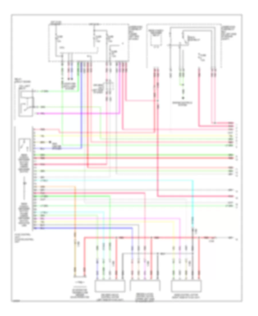
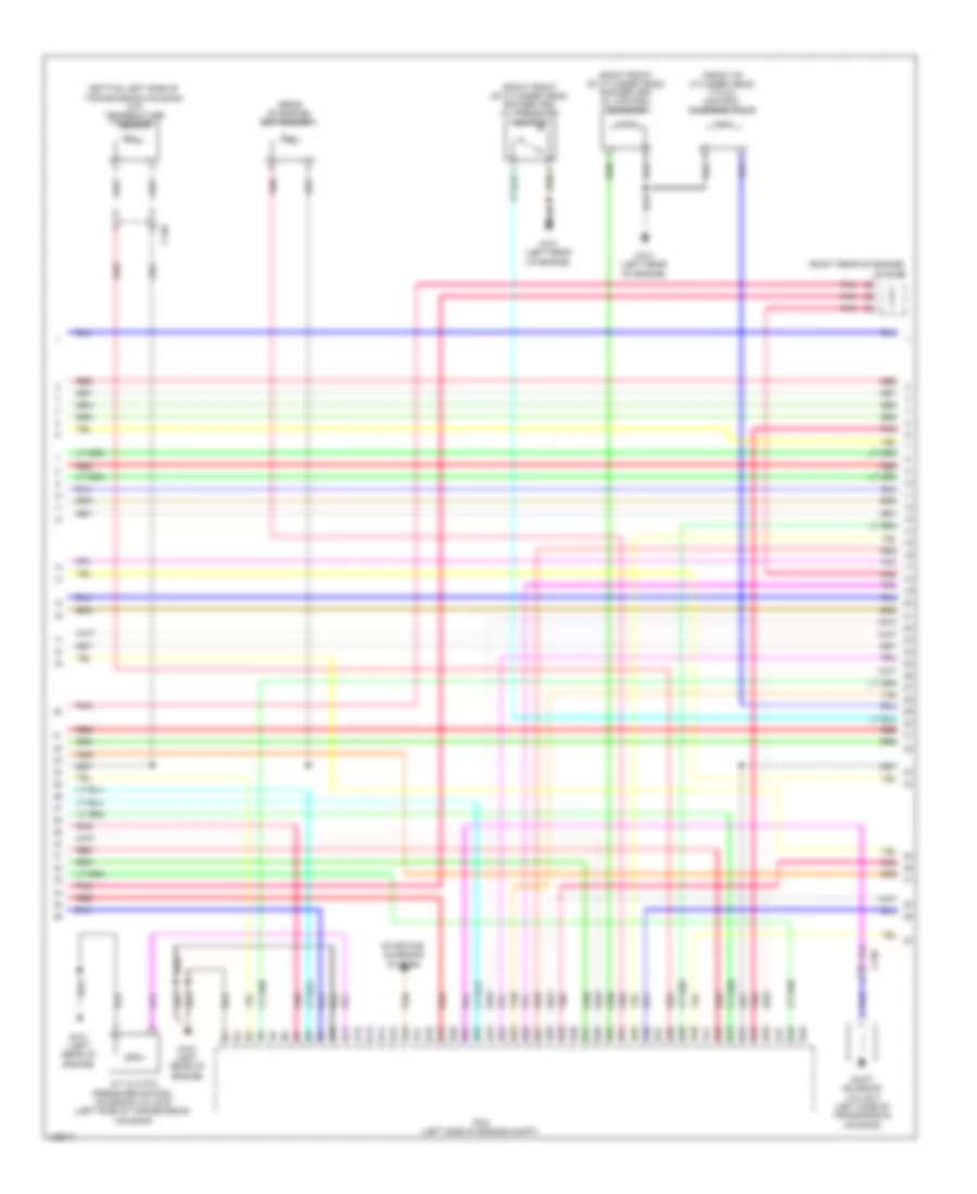
2.4L, Engine Performance Wiring Diagram (3 of 5) for Honda CR-V LX 2014
List of elements for 2.4L, Engine Performance Wiring Diagram (3 of 5) for Honda CR-V LX 2014:
- (bottom left side of transmission housing) atf temperature sensor
- (front of cylinder head) vtc oil control solenoid valve
- (rear of engine) ect sensor 1
- (right front of cylinder head) rocker arm oil control solenoid
- (right front of cylinder head) rocker arm oil pressure switch
- (right rear of engine) j/c c136
- A/t clutch pressure control solenoid valve b (left side of transmission housing)
- B10
- B11
- B12
- B13
- B14
- B15
- B16
- B17
- B18
- B19
- B20
- B21
- B22
- B23
- B24
- B25
- B26
- B27
- B28
- B29
- B30
- B31
- B32
- B33
- B34
- B35
- B36
- B37
- B38
- B39
- B40
- B41
- B42
- B43
- B44
- B45
- B46
- B47
- B48
- B49
- C130
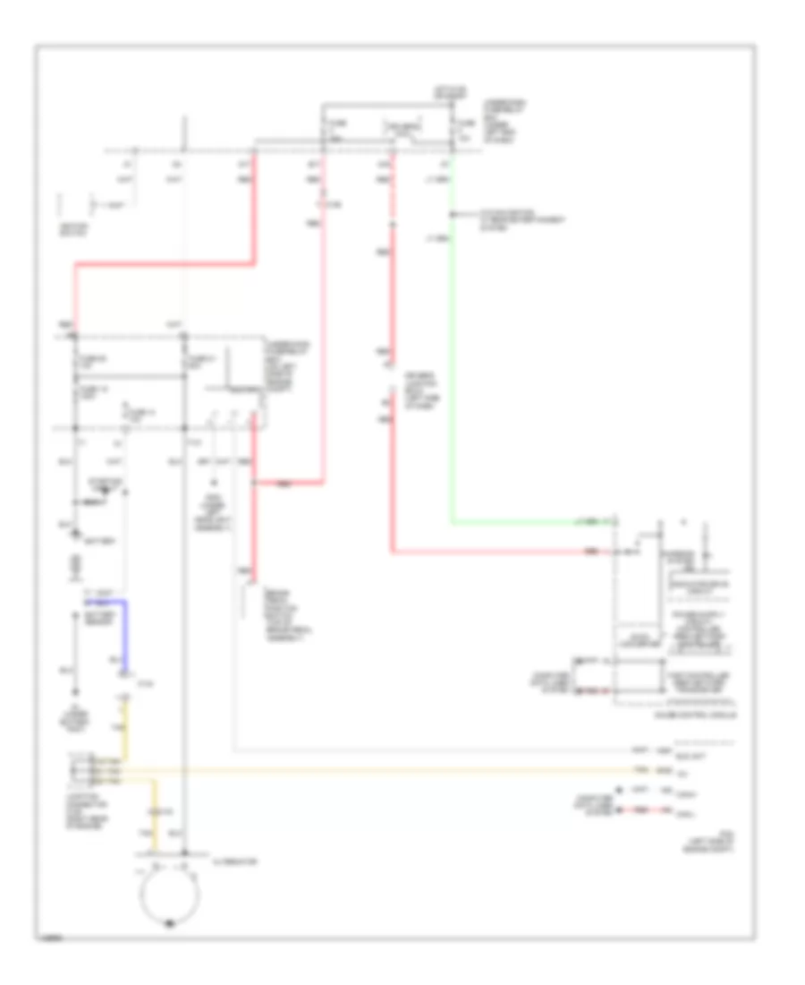
- G101 (left rear of engine)
- Pcm (left side of engine compt)
- Pnk
- Red
- Shift solenoid valve a (left side of transmission housing)
- Starting/ charging system
- Tan
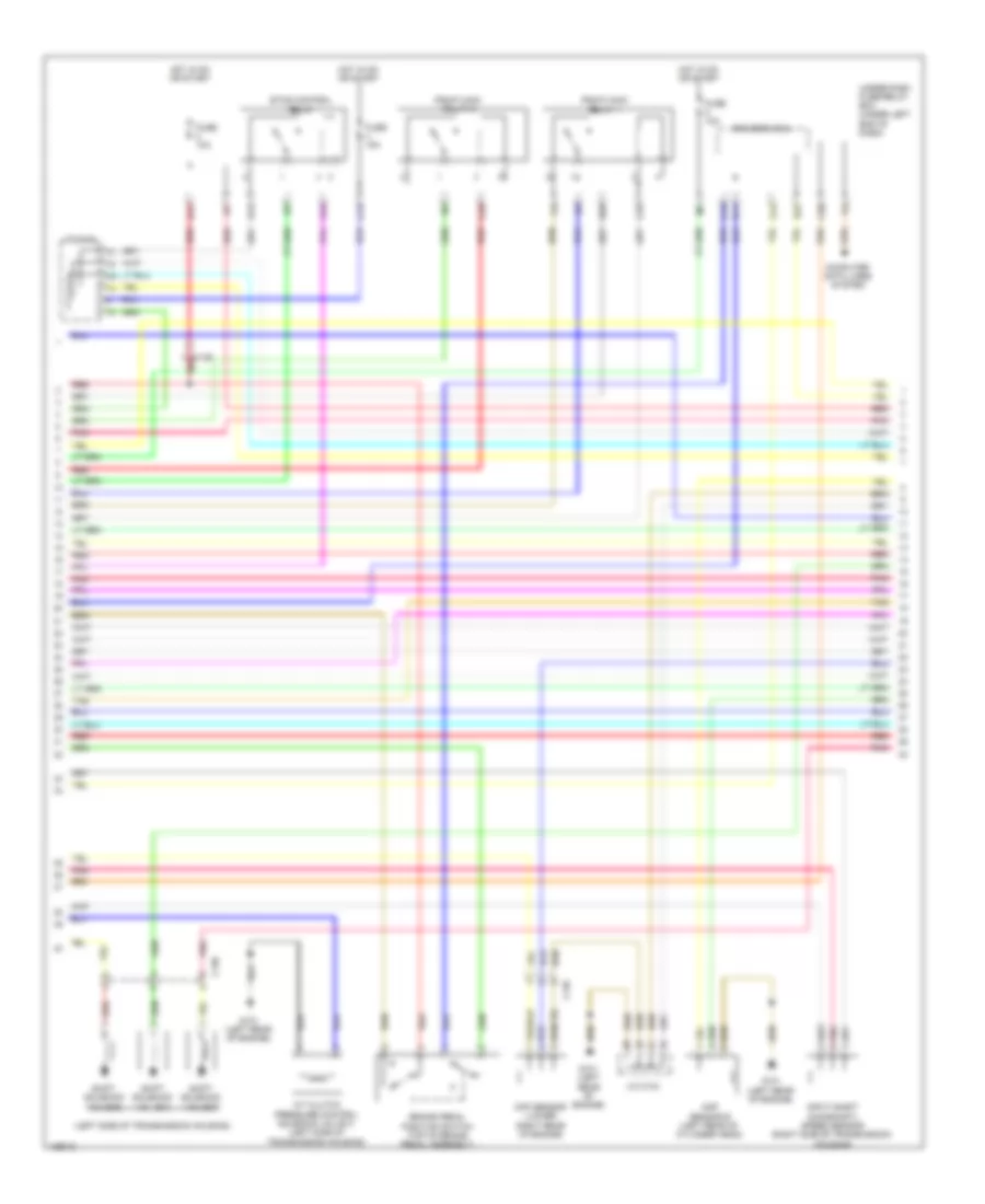
2.4L, Engine Performance Wiring Diagram (4 of 5) for Honda CR-V LX 2014
List of elements for 2.4L, Engine Performance Wiring Diagram (4 of 5) for Honda CR-V LX 2014:
- (left side of transmission housing)
- A/t clutch pressure control solenoid valve c (left side of transmission housing)
- B17
- Brake pedal position switch (top of brake pedal assembly)
- C126 red
- C13
- C130
- C135
- C16
- C20
- C24
- C25
- C34
- C35
- Ckp sensor (lower right rear of engine)
- Cmp sensor b (left rear of cylinder head)
- Computer data lines system
- D11
- D12
- D22
- D26
- Driver's micu
- Etcs control relay
- Fuse 10a
- Fuse 15a
- G101 (left rear of engine)
- Hot in on or start
- Input shaft (mainshaft) speed sensor (right side of transmission housing)
- J/c c134
- Pgm-fi main relay 1
- Pgm-fi main relay 2
- Pnk
- Red
- Shift solenoid valve c
- Shift solenoid valve d
- Shift solenoid valve e
- Tan
- Under-dash fuse/relay box (under left end of dash)
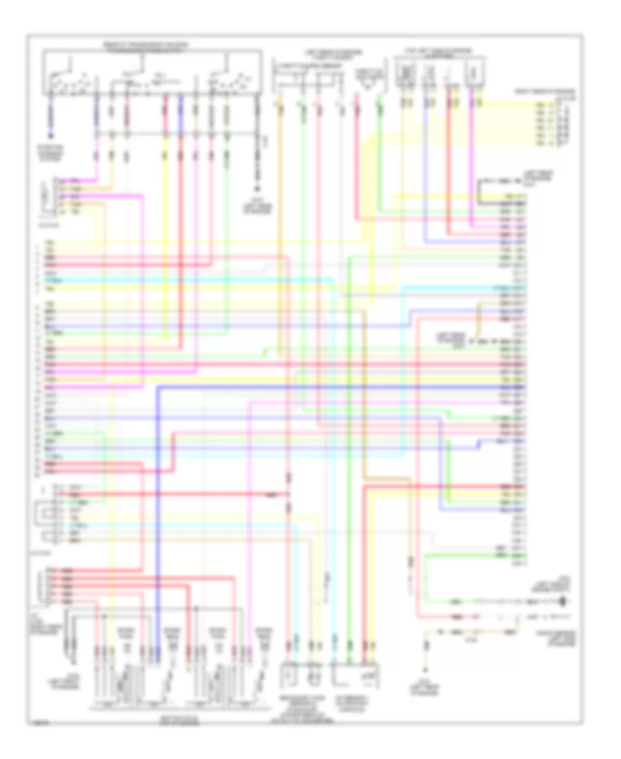
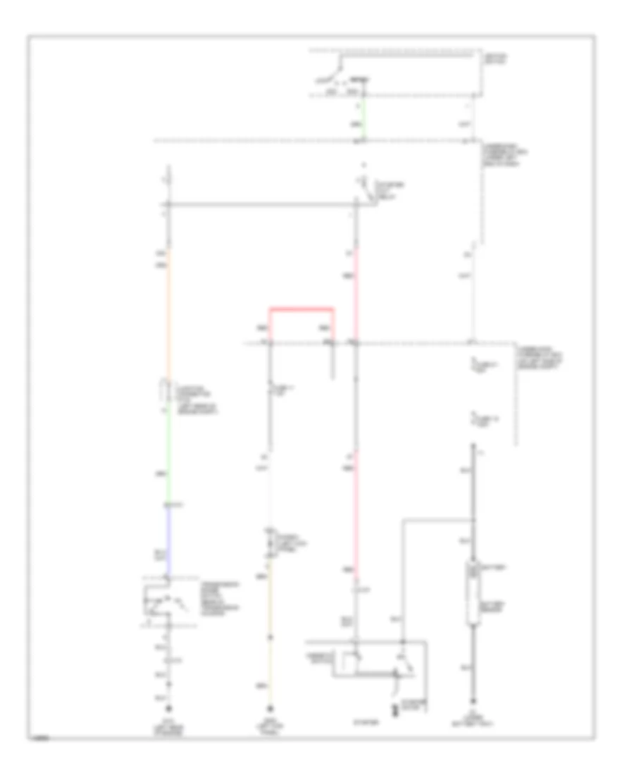
2.4L, Engine Performance Wiring Diagram (5 of 5) for Honda CR-V LX 2014
List of elements for 2.4L, Engine Performance Wiring Diagram (5 of 5) for Honda CR-V LX 2014:
- (left rear of engine) g101
- (left rear of engine) throttle body
- (rear of transmission housing) transmission range switch
- (right rear of engine)
- (top left side of engine) injectors
- 2-1
- A/f sensor 1 (on exhaust manifold)
- C10
- C11
- C12
- C13
- C131
- C132
- C14
- C15
- C16
- C17
- C18
- C19
- C20
- C21
- C22
- C23
- C24
- C25
- C26
- C27
- C28
- C29
- C30
- C31
- C32
- C33
- C34
- C35
- C36
- C37
- C38
- C39
- C40
- C41
- C42
- C43
- C44
- C45
- C46
- C47
- C48
- C49
- G101 (left rear of engine)
- G102 (left front of engine)
- Icm
- Ignition coils (top of engine)
- J/c c134
- J/c c136
- J/c c136 (right rear of engine)
- Knock sensor (left side of engine)
- Pcm (left side of engine compt)
- Pnk
- Red
- Secondary ho2s (sensor 2) (in exhaust, downstream of catalytic converter)
- Spark plug
- Starting/ charging system
- Tan
- Throttle actuator
- Throttle open sensor
EXTERIOR LIGHTS
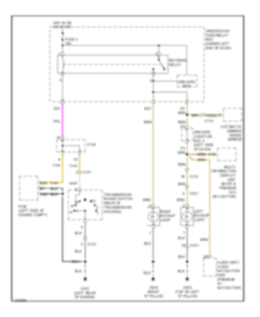
Backup Lamps Wiring Diagram for Honda CR-V LX 2014
List of elements for Backup Lamps Wiring Diagram for Honda CR-V LX 2014:
- A14
- Audio unit/ audio navigation unit (premium w/ navigation)
- Automatic dimming inside mirror
- B21
- B25
- C112
- C114
- C121
- C131
- C134
- C20
- D21
- Driver's junction box 2 (left side of dash)
- Driver's micu
- Fuse 5 10a
- G101 (left rear of engine)
- G603 (top of left "d" pillar)
- G604 (right "d" pillar)
- Hot in on or start
- Left backup light
- Multi- information display unit (base & premium w/o navigation)
- Pcm (left side of engine compt)
- Reverse relay
- Right backup light
- Tan
- Transmission range switch (rear of transmission housing)
- Under-dash fuse/relay box (under left end of dash)
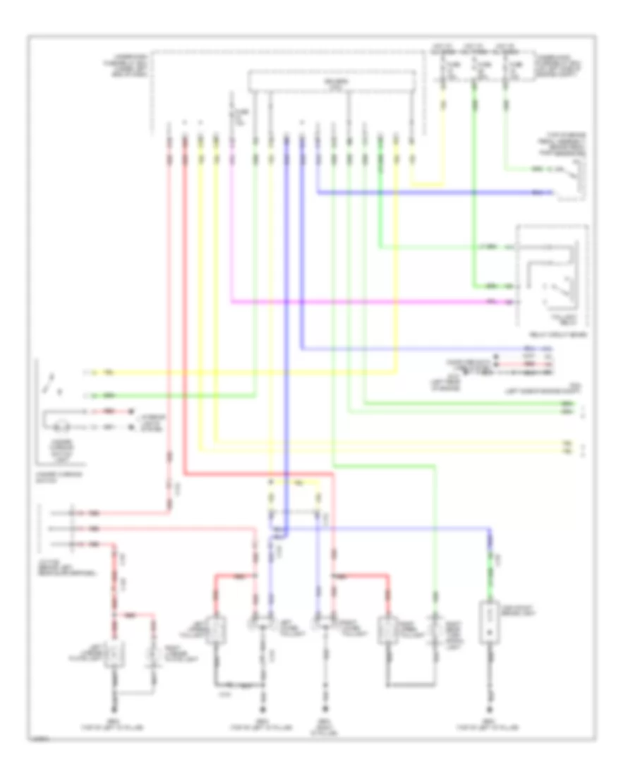
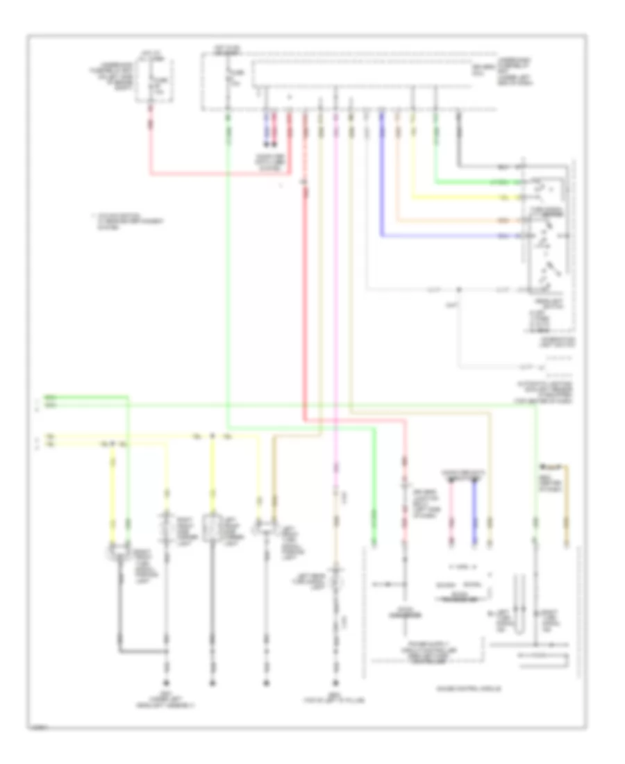
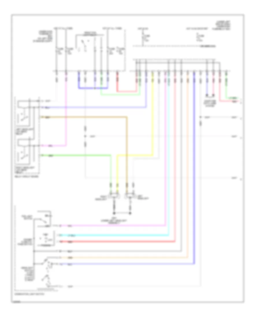
Exterior Lamps Wiring Diagram (1 of 2) for Honda CR-V LX 2014
List of elements for Exterior Lamps Wiring Diagram (1 of 2) for Honda CR-V LX 2014:
- (top of brake pedal assembly) brake pedal position switch
- A13
- B12
- B35
- C112
- C12
- C121
- C127
- C145
- C16
- C19
- C33
- C38
- D11
- Driver's micu
- Fuse 10a
- Fuse 20a
- G101 (left rear of engine)
- G603 (top of left "d" pillar)
- G604 (right "d" pillar)
- Hazard warning switch
- Hazard warning switch light
- High mount brake light
- Hot at all times
- Interior lights system
- J/c c128 (behind left rear quarterpanel)
- Left license plate light
- Left lower taillight
- Left upper taillight
- P19
- Pcm (left side of engine compt)
- Q15
- Red
- Relay circuit board
- Right license plate light
- Right lower taillight
- Right rear turn signal light
- Right upper taillight
- Taillight relay
- Under-dash fuse/relay box (under left end of dash)
- Under-hood fuse/relay box (on left side of engine compt)
Exterior Lamps Wiring Diagram (2 of 2) for Honda CR-V LX 2014
List of elements for Exterior Lamps Wiring Diagram (2 of 2) for Honda CR-V LX 2014:
- 0) off 1) park 2) auto 3) head
- Automatic lighting/ sunlight sensor (if equipped) (top center of dash)
- B-can transceiver
- B-canh
- B-canl
- C11
- C121
- Combination light switch
- Computer data lines system
- D17
- Dc/dc converter
- Driver's junction box 2 (left side of dash)
- Driver's micu
- Fuse 10a
- G301 (under left headlight assembly)
- G502 (center of dash)
- G603 (top of left "d" pillar)
- Gauge control module
- Headlight switch
- Hot at all times
- Hot in on or start
- Left front side marker light
- Left front turn signal/ parking light
- Left rear turn signal light
- Left turn signal ind
- Pnk
- Q16
- Red
- Right front side marker light
- Right front turn signal/ parking light
- Right turn signal ind
- T13
- T14
- Turn signal switch
- Under-dash fuse/relay box (under left end of dash)
- Under-hood fuse/relay box (on left side of engine compt)
- W/o navigation w/ rear entertainment system
GROUND DISTRIBUTION
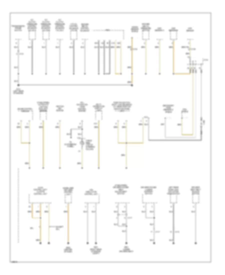
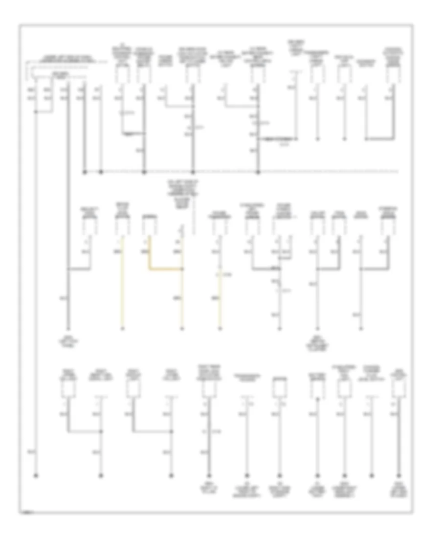
Ground Distribution Wiring Diagram (1 of 4) for Honda CR-V LX 2014
List of elements for Ground Distribution Wiring Diagram (1 of 4) for Honda CR-V LX 2014:
- (if equipped) automatic lighting/ sunlight sensor
- (if equipped) driver's power seat adjustment switch
- A/t clutch pressure control solenoid valve a
- A/t clutch pressure control solenoid valve b
- A/t clutch pressure control solenoid valve c
- A10
- B10
- C105
- C117
- C118
- C13
- C131
- C132
- C134
- C135
- C15
- C20
- Cable reel (top of steering column)
- Ckp sensor
- Cmp sensor a
- Cmp sensor b
- Dlc
- Driver's power lumbar support switch
- Driver's seat belt buckle switch
- Except exl
- Exl
- G101 (left rear of engine)
- G201 (right rear of engine compt)
- G502 (center of dash)
- G601 (under driver's seat)
- Gauge control module
- Hfl- navigation voice control switch
- Hvac control unit/ climate control unit
- Ignition key switch
- Imm0bilizer keyless control unit
- Knock sensor shield
- Left rear door lock actuator/ knob switch
- Multi- information display unit
- Park pin switch/ shift lock solenoid/ a/t gear position indicator panel light
- Pcm
- Pcm shield
- Rocker arm oil control solenoid
- Rocker arm oil pressure switch
- Secondary ho2s (sensor 2) shield
- T6 (in steering wheel)
- Transmission range switch
- Vsa modulator control unit
- Vtc oil control solenoid valve
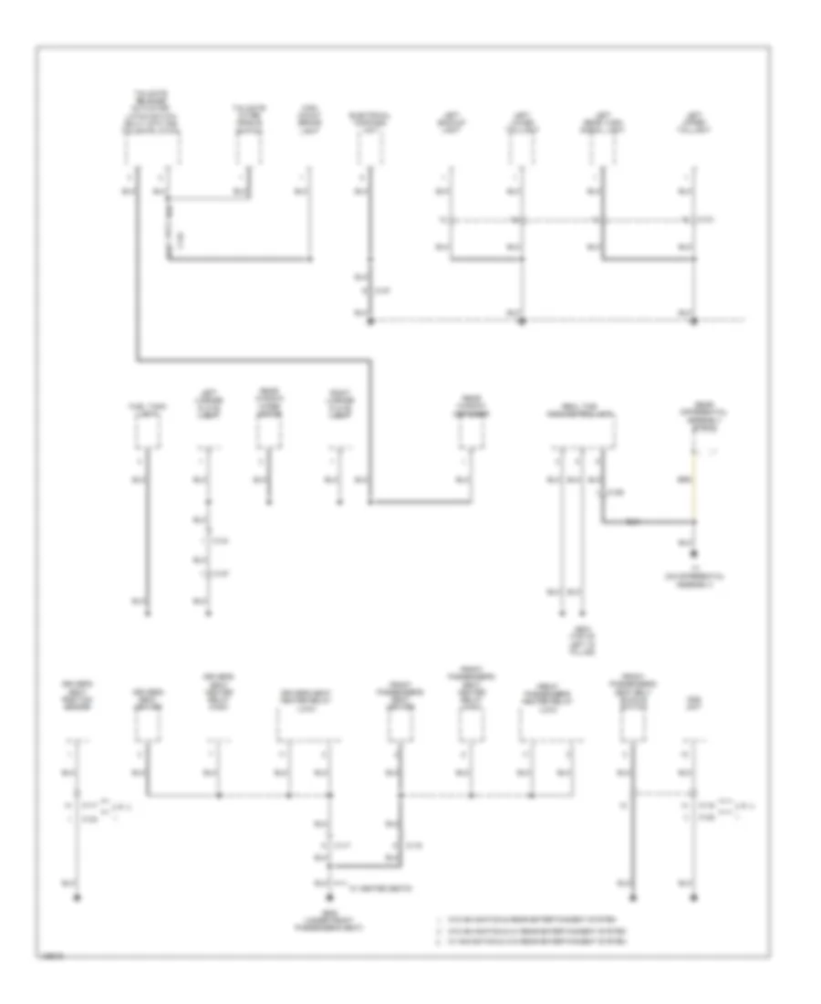
Ground Distribution Wiring Diagram (2 of 4) for Honda CR-V LX 2014
List of elements for Ground Distribution Wiring Diagram (2 of 4) for Honda CR-V LX 2014:
- (canada) automatic dimming inside mirror
- (canada) washer fluid level switch
- (if equipped) left power mirror
- (if equipped) moonroof control unit/ motor
- (if equipped) right fog light
- (on left side of engine compt) under-hood fuse/relay box
- (under left end of dash) under-dash fuse/relay box
- (w/ rear
- (w/ rear entertainment) rear controller & screen
- B20
- B32
- Battery sensor
- Blower motor relay
- Brake fluid level switch
- C111
- C114
- C119
- C138
- Console accessory power socket relay
- D10
- Diode c
- Driver's door lock actuator/ knob switch/ key cylinder switch
- Driver's micu
- Driver's vanity mirror light
- Econ switch
- Engine
- Entertainment) ceiling light
- Eps control unit
- G1 (under battery tray)
- G2 (right side of engine compt)
- G202 (under right headlight assembly)
- G3 (lower left front of engine compt)
- G402 (left kick panel)
- G403 (upper left end of dash)
- G501 (behind instrument cluster)
- G604 (right "d" pillar)
- Individual map light
- Moonroof switch
- Passenger's vanity mirror light
- Power mirror switch
- Power transistor
- Power window master switch
- Right backup light
- Right lower taillight
- Right rear door lock actuator/ knob switch
- Right rear turn signal light
- Right upper taillight
- Security hood switch
- Steering angle sensor
- Tpms switch
- Transmission housing
- Vsa off switch
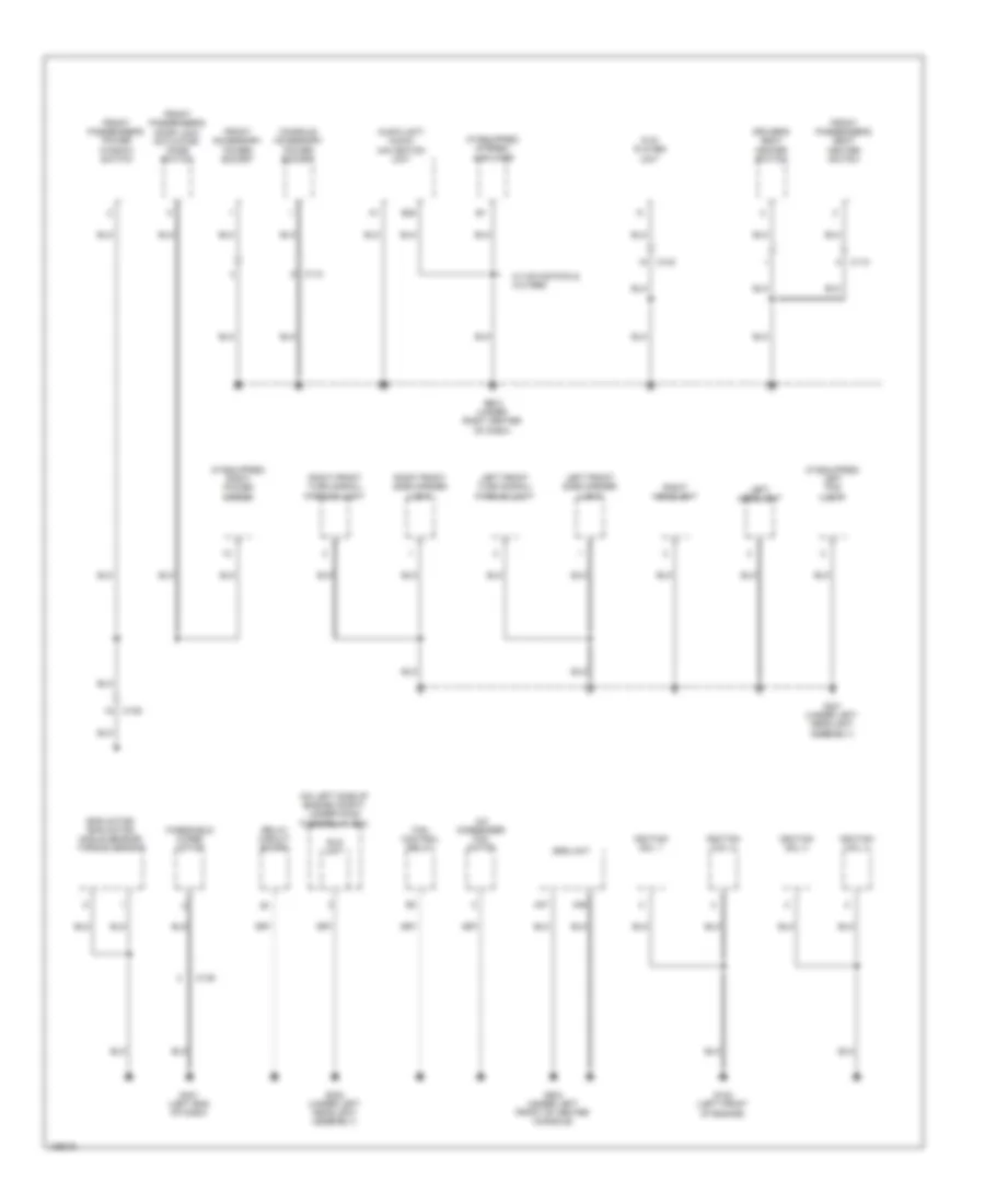
Ground Distribution Wiring Diagram (3 of 4) for Honda CR-V LX 2014
List of elements for Ground Distribution Wiring Diagram (3 of 4) for Honda CR-V LX 2014:
- C116
- C117
- C121
- C124
- C125
- C127
- C129
- C144
- C145
- Driver's seat heater
- Driver's seat heater relay (high)
- Driver's seat heater relay (low)
- Driver's seat position sensor
- Electrical compass unit
- Front passenger's heater relay (low)
- Front passenger's seat belt buckle switch
- Front passenger's seat heater
- Front passenger's seat heater relay (high)
- Fuel tank unit
- G602 (under front passenger's seat)
- G603 (top of left "d" pillar)
- High mount brake light
- Left backup light
- Left license plate light
- Left lower taillight
- Left rear turn signal light
- Left upper taillight
- Ods unit
- Real time awd control unit
- Rear differential assembly shield
- Rear window defogger
- Rear window wiper motor
- Right license plate light
- T7 (on differential assembly)
- Tailgate outer handle switch
- Tailgate release actuator/ latch switch (built into the tailgate latch)
- W/ heated seats
- W/ navigation & w/o rear entertainment system
- W/o navigation & rear entertainment system
- W/o navigation & w/ rear entertainment system
Ground Distribution Wiring Diagram (4 of 4) for Honda CR-V LX 2014
List of elements for Ground Distribution Wiring Diagram (4 of 4) for Honda CR-V LX 2014:
- (if equipped) left fog light
- (if equipped) right power mirror
- (if equipped) stereo amplifier
- (on left side of engine compt) under-hood fuse/relay box
- A/c condenser fan motor
- A36
- A37
- Audio unit/ audio- navigation unit
- B20
- C103
- C109
- C110
- C139
- Console accessory power socket
- Driver's seat heater switch
- Dvd player unit
- Eld unit
- Eps motor/ eps motor angle sensor/ torque sensor
- Fan control relay
- Front accessory power socket
- Front passenger's door lock actuator/ knob switch
- Front passenger's power window switch
- Front passenger's seat heater switch
- G102 (left front of engine)
- G301 (under left headlight assembly)
- G302 (under left headlight assembly)
- G401 (left end of dash)
- G503 (under right center of dash)
- G504 (under left front of center console)
- Ignition coil 1
- Ignition coil 2
- Ignition coil 3
- Ignition coil 4
- Left front side marker light
- Left front turn signal/ parking light
- Left headlight
- Relay circuit board
- Right front side marker light
- Right front turn signal/ parking light
- Right headlight
- Srs unit
- W/ navigation & w/o res
- Windshield wiper motor
HEADLIGHTS
Headlights Wiring Diagram (1 of 2) for Honda CR-V LX 2014
List of elements for Headlights Wiring Diagram (1 of 2) for Honda CR-V LX 2014:
- (under left end of dash) under-dash fuse/relay box
- C14
- C18
- Combination light switch
- Computer data lines system
- D16
- D17
- D25
- Dimmer/ flash-to- pass switch
- Driver's micu
- Fog light switch
- Front fog light relay
- Fuse 10a
- Fuse 20a
- Fuse 7.5a
- G301 (under left headlight assembly)
- Headlight switch 0) off 1) park 2) auto 3) head
- High
- Hot at all times
- Hot in on
- Hot in on or start
- Left headlight
- Left headlight low beam relay
- Low
- Off
- Passing
- Pnk
- Q16
- Red
- Relay circuit board
- Right headlight
- Right headlight low beam relay
- T11
- T12
- Under-hood fuse/relay box (on left side of engine compt)
Headlights Wiring Diagram (2 of 2) for Honda CR-V LX 2014
List of elements for Headlights Wiring Diagram (2 of 2) for Honda CR-V LX 2014:
- (center of dash) g502
- 10v stabilizing circuit
- Air conditioning system
- Automatic lighting/ sunlight sensor (if equipped) (top center of dash)
- B-can h
- B-can l
- B-can transceiver
- C103
- C104
- C108
- Computer data lines system
- Dc/dc converter
- Dimming circuit
- Driver's junction box 2 (left side of dash)
- Dvd player unit
- Exl
- Front fog light indicator (led)
- G202 (under right headlight assembly)
- G301 (under left headlight assembly)
- Gauge control module
- High beam indicator (led)
- Indicator drive circuit
- Left fog light
- Lights control indicator (led)
- Lights on indicator (led)
- Parking brake switch (base of parking brake lever assembly)
- Pnk
- Rear controller & screen
- Red
- Right fog light
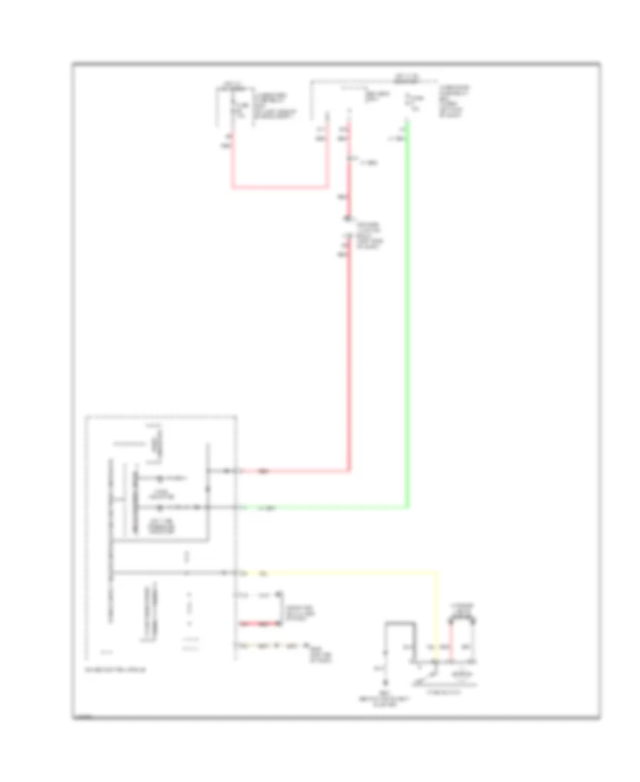
HORN
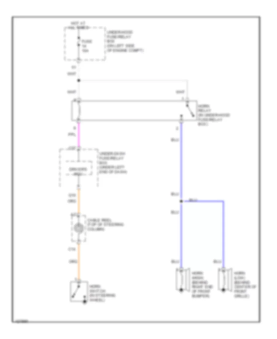
Horn Wiring Diagram for Honda CR-V LX 2014
List of elements for Horn Wiring Diagram for Honda CR-V LX 2014:
- C14
- C37
- Cable reel (top of steering column)
- Driver's mcu
- Fuse 10a
- Horn (high) (behind right end of front bumper)
- Horn (low) (behind center of front grille)
- Horn relay (in under-hood fuse/relay box)
- Horn switch (in steering wheel)
- Hot at all times
- Q10
- Under-dash fuse/relay box (under left end of dash)
- Under-hood fuse/relay box (on left side of engine compt)
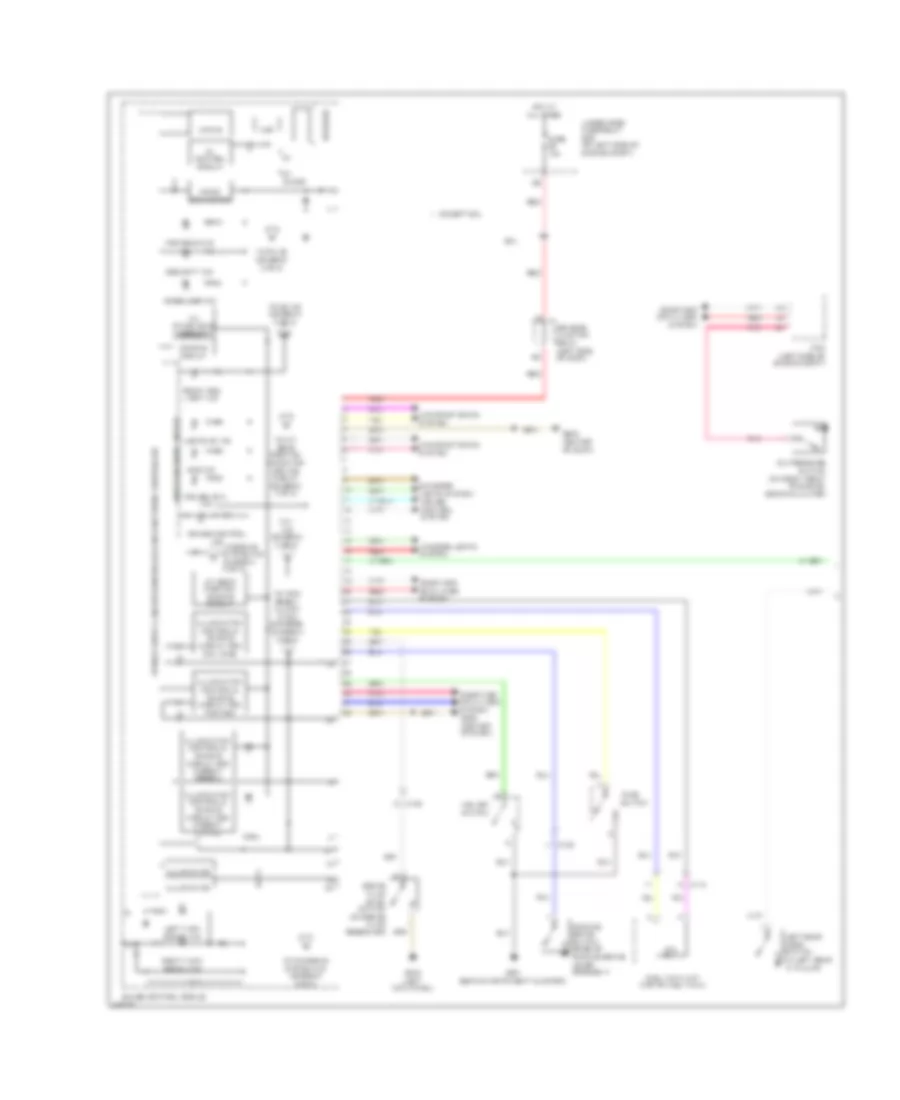
INSTRUMENT CLUSTER
Instrument Cluster Wiring Diagram (1 of 2) for Honda CR-V LX 2014
List of elements for Instrument Cluster Wiring Diagram (1 of 2) for Honda CR-V LX 2014:
- 10v stabilizing circuit
- 5v control circuit
- 5v on/off
- A/t gear position dimming circuit
- Air conditioning system
- Amp
- Brake fluid level switch (on brake fluid reservoir)
- C108
- C112
- Computer data lines system
- Cruise control ind to brake system ind (diagram 2 of 2)
- Cruise control system
- Cruise main ind
- Dc/dc converter
- Dimming circuit
- Driver's junction box 2 (left side of dash)
- Eco ind
- Except exl
- Exl
- Exterior lights system
- Front fog light ind
- Fuel tank unit (top of fuel tank)
- Fuse 10a
- G402 (left kick panel)
- G501 (behind instrument cluster)
- G502 (center of dash)
- Gauge control module
- High beam ind
- Hot at all times
- Illumination
- Illumination control & dimming circuit for ambient (green)
- Illumination control & dimming circuit for ambient (white)
- Illumination control & dimming circuit for dial face
- Illumination control & dimming circuit for pointer
- Immobilizer ind
- Indicator drive circuit
- Interior lights system
- Left rear door switch (in left rear "c" pillar)
- Left turn signal ind
- Lights on ind
- Mixing
- Oil pressure switch (on right front of engine, above oil filter)
- Parking brake switch (base of parking brake lever assembly)
- Pcm (left side of engine compt)
- Pnk
- Red
- Right turn signal ind
- Security ind
- Speaker
- To 1 ind (diagram 2 of 2)
- To a/t gear position indicator driving circuit (diagram 2 of 2)
- To charging system ind (diagram 2 of 2)
- To d3 ind (diagram 2 of 2)
- To pin 22 (diagram 2 of 2)
- To trip reset/ illumin- ation encoder (diagram 2 of 2)
- Tpms switch
- Under-hood fuse/relay box (on left side of engine compt)
- Vsa off switch
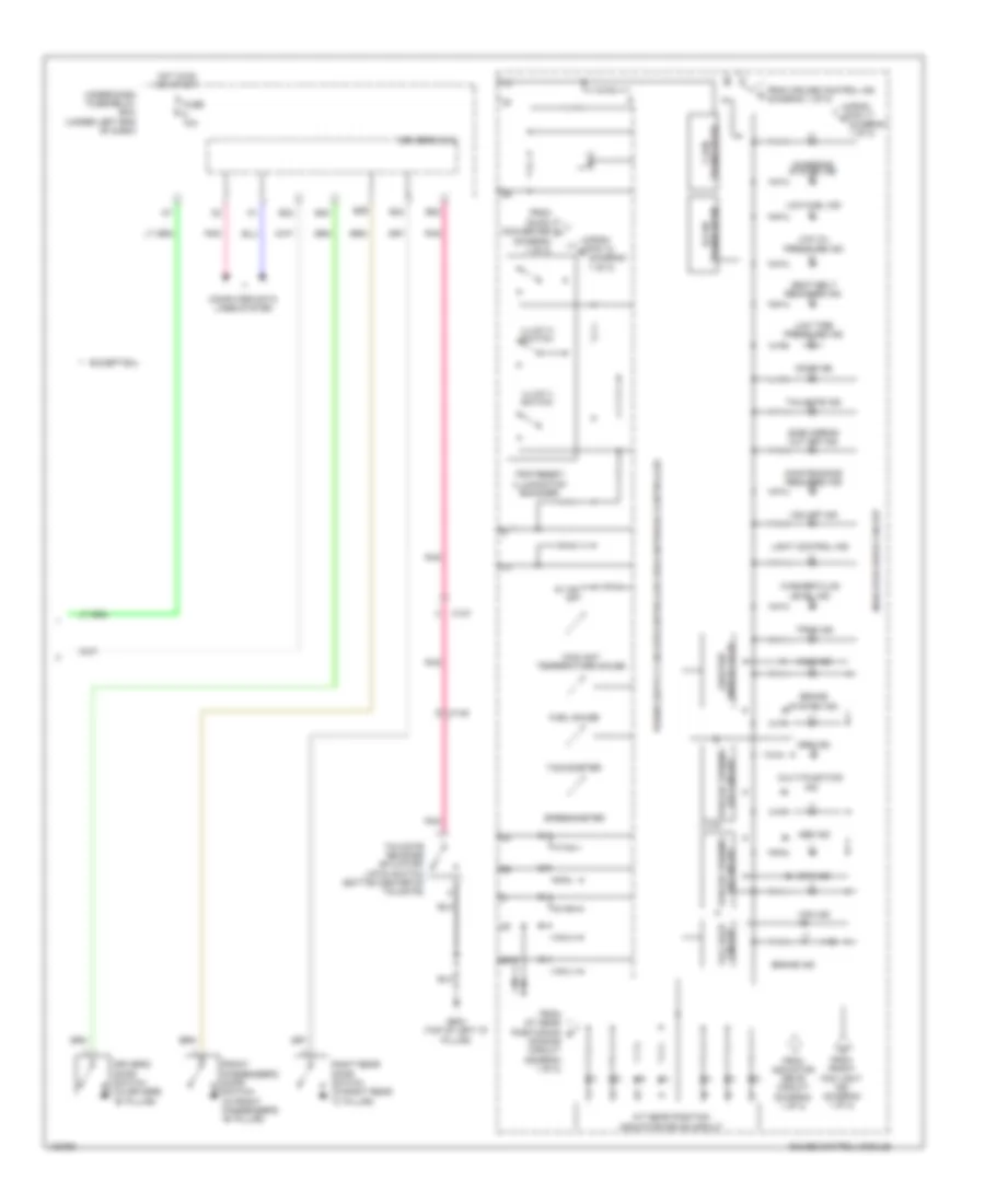
Instrument Cluster Wiring Diagram (2 of 2) for Honda CR-V LX 2014
List of elements for Instrument Cluster Wiring Diagram (2 of 2) for Honda CR-V LX 2014:
- (diagram 1 of 2)
- 5v on/ off
- A/t gear position indicator drive circuit
- Abs ind
- Awd ind
- B22
- B29
- B33
- B34
- B40
- Brake ind
- Brake system ind
- C127
- C145
- Charging system ind
- Circuit fall safe
- Computer data lines system
- Coolant temperature gauge
- Dimming circuit (diagram 1 of 2)
- Display (lcd) odo/trip
- Door ind
- Driver's door switch (in driver's "b" pillar)
- Driver's micu
- Eps ind
- Except exl
- From a/t gear positioning g
- From cruise control ind (diagram 1 of 2)
- From dc/dc converter f
- From front fog light ind (diagram 1 of 2)
- From indicator drive circuit (diagram 1 of 2)
- From pin 12 e
- From pin 17 a
- Front passenger's door switch (in front passenger's "b" pillar)
- Fuel gauge
- Fuse 10a
- G603 (top of left "d" pillar)
- Gauge control module
- Hot in on or start
- Illum (+) switch
- Illum (-) switch
- Indicator drive circuit
- Level ind
- Light control ind
- Low fuel ind
- Low oil pressure ind
- Low tire pressure ind
- Maintenance required ind
- Multi-function ind
- Off circuit forced turning
- On circuit forced turning
- Pnk
- Right rear door switch (in right rear "c" pillar)
- Seat belt reminder ind
- Side airbag cut off ind
- Speedometer
- Srs ind
- Tachometer
- Tailgate ind
- Tailgate release actuator/ latch switch (bottom center of tailgate)
- Tpms ind
- Transciever b-can
- Transciever f-can
- Trip reset/ illumination encoder
- Under-dash fuse/relay box (under left end of dash)
- Vsa ind
- Vsa off ind
- Washer fluid
INTERIOR LIGHTS
Courtesy Lamps Wiring Diagram for Honda CR-V LX 2014
List of elements for Courtesy Lamps Wiring Diagram for Honda CR-V LX 2014:
- (behind instrument cluster)
- (left side of dash) driver's junction box 2
- (or pnk)
- (w/o navigation w/ res & w/ navigation w/o res) ceiling light
- Ambient light/ microphone (if equipped) (in roof console)
- B22
- B23
- B29
- B33
- B34
- B39
- B40
- C108
- C114
- C127
- C145
- Cargo area light
- Ceiling light (w/o navigation & res)
- Computer data lines system
- Door
- Driver's door switch (in driver's "b" pillar)
- Driver's micu
- Driver's vanity mirror light
- Front passenger's door switch (in front passenger's "b" pillar)
- Front passenger's vanity mirror light
- Fuse 7.5a
- G501
- G501 (behind instrument cluster)
- G603 (top of left "d" pillar)
- Hot at all times
- Individual map lights (w/o navigation & res)
- Individual map lights (w/o navigation w/ res & w/ navigation w/o res)
- Interior light cut relay
- Left rear door switch (in left rear "c" pillar)
- Moonroof switch (if equipped)
- Off
- Pnk
- Right rear door switch (in right rear "c" pillar)
- Tailgate release actuator/latch switch (built into the tailgate latch) (bottom center of tailgate)
- Under-dash fuse/ relay box (under left end of dash)
- Under-hood fuse/relay box (on left side of engine compt)
- W/ navigation & w/o res
- W/o navigation & res
- W/o navigation & w/ res
Entry Light Timer Wiring Diagram for Honda CR-V LX 2014
List of elements for Entry Light Timer Wiring Diagram for Honda CR-V LX 2014:
- (left side of dash) driver's junction box 2
- (w/o navigation w/ res & w/ navigation w/o res) ceiling light
- Ambient light/ microphone (if equipped) (microphone: in roof console)
- B23
- B29
- B33
- B34
- B40
- C102
- C108
- C114
- C127
- Cargo area light
- Ceiling light (w/o navigation & res)
- Computer data lines system
- Door
- Driver's door lock actuator/ knob switch/key cylinder switch (in driver's door)
- Driver's door switch (in driver's "b" pillar)
- Driver's micu
- Driver's vanity mirror light
- Front passenger's vanity mirror light
- Front passengers door switch (in front passenger's "b" pillar)
- Fuse 7.5a
- G501 (behind instrument cluster)
- G502 (behind instrument cluster)
- Hot at all times
- Ignition key switch
- Individual map lights (w/o navigation & res)
- Individual map lights (w/o navigation w/ res & w/ navigation w/o res)
- Interior light cut relay
- Key
- Left rear door switch (in left rear "c" pillar)
- Lock
- Moonroof switch (if equipped)
- N13
- Off
- P11
- P12
- Pnk
- Right rear door switch (in right rear "c" pillar)
- Under-dash fuse/ relay box (under left end of dash)
- Under-hood fuse/relay box (on left side of engine compt)
- Unlock
- W/ navigation & w/o res
- W/o navigation & res
- W/o navigation & w/ res
Instrument Illumination Wiring Diagram (1 of 2) for Honda CR-V LX 2014
List of elements for Instrument Illumination Wiring Diagram (1 of 2) for Honda CR-V LX 2014:
- Auto
- Automatic lighting/ sunlight sensor (top center of dash)
- B27
- C103
- C104
- C110
- C112
- C113
- C114
- C118
- C119
- C12
- C19
- Combination light switch
- Computer data lines system
- D17
- Dimmer/flash-to-pass switch
- Driver's junction box 2 (left side of dash)
- Driver's micu
- Driver's seat heaters switch (if equipped)
- Dvd player unit (if equipped)
- Front passengers seat heaters switch (if equipped)
- Fuse 20 7.5a
- Fuse 35 7.5a
- Fuse 5 10a
- Hazard warning switch
- Head
- Headlight switch
- Hot in on or start
- Hvac control unit/ climate control unit
- K10
- Left rear power window switch
- Moonroof switch (if equipped)
- Off
- Park
- Park pin switch/ shift lock solenoid/ a/t gear position indicator panel light (base of shift lever assembly)
- Pass
- Pnk
- Q16
- Rear controller & screen (if equipped)
- Red
- Right rear power window switch
- T11
- T12
- Tpms switch
- Under-dash fuse/relay box (under left end of dash)
- Vsa off switch
- W/ navigation & res
- W/o navigation & res
- W/o navigation & w/ res
Instrument Illumination Wiring Diagram (2 of 2) for Honda CR-V LX 2014
List of elements for Instrument Illumination Wiring Diagram (2 of 2) for Honda CR-V LX 2014:
- (center of dash) g502
- 10v stabilizing circuit
- A10
- Ambient light/ microphone (in roof console)
- Audio remote multi-information display switch
- B-can h
- B-can l
- C109
- C111
- C114
- Cable reel (top of steering column)
- Computer data lines system
- Converter dc/dc
- Cruise control combination switch
- Dimming circuit
- Econ switch
- Front passengers air bag cut-off indicator
- Front passengers power window switch
- Fuse 26 20a
- Fuse 29 10a
- Gauge control module
- Hfl-navigation voice control switch
- Hot at all times
- Illumi (+) switch
- Illumi (-) switch
- Illumination control
- Illumination control dimming circuit for ambient (green)
- Illumination control dimming circuit for ambient (white)
- Illumination control dimming circuit for dial face (white)
- Illumination control dimming circuit for pointer (white)
- Illumination encoder/ trip reset
- Led
- Pnk
- Power mirror switch
- Power window master switch
- Red
- Relay circuit board
- Tail light relay
- Transceiver b-can
- Under-hood fuse/relay box (on left side of engine compt)
NAVIGATION
Compass Wiring Diagram for Honda CR-V LX 2014
List of elements for Compass Wiring Diagram for Honda CR-V LX 2014:
- (top of left "d" pillar) g603
- A24
- Audio unit/ audio-navigation unit
- B10
- B13
- B19
- B20
- B28
- C107
- C122
- Computer data lines system
- Driver's junction box 2 (left side of dash)
- Electrical compass unit (left rear of roof)
- Fuse 10a
- Fuse 7.5a
- G503 (under right center of dash)
- Hot in on or acc
- Hot in on or start
- Pnk
- Under-dash fuse/relay box (under left end of dash)
- W/ rear entertainment
Hands Free Module Wiring Diagram (1 of 2) for Honda CR-V LX 2014
List of elements for Hands Free Module Wiring Diagram (1 of 2) for Honda CR-V LX 2014:
- Ambient light/microphone
- C114
- C13
- C20
- Cable reel (top of steering column)
- Driver's junction box 2 (left side of dash)
- Fuse 7.5a
- G502 (center of dash)
- Handsfreelink control unit (under middle of dash)
- Hfl navigation voice control switch
- Hot in acc or on
- Interior lights system
- Microphone
- Microphone (in roof console)
- Off hook
- On hook/ back
- Pnk
- Red
- T6 (in steering wheel)
- Talk
- Under-dash fuse/relay box (under left end of dash)
- W/ navigation
- W/o navigation
Hands Free Module Wiring Diagram (2 of 2) for Honda CR-V LX 2014
List of elements for Hands Free Module Wiring Diagram (2 of 2) for Honda CR-V LX 2014:
- (under middle of dash) g503
- A10
- A11
- A12
- A24
- A25
- A26
- A27
- A32
- Audio unit/ audio-navigation unit
- B11
- B12
- B13
- C10
- C11
- C12
- Center junction box
- Computer data lines system
- E10
- E13
- G10
- H10
- Multi-information display unit
- Pnk
- Red
- W/ navigation
- W/o navigation
- Xm receiver (if equipped) (behind right kick panel)
Navigation Wiring Diagram (1 of 4) for Honda CR-V LX 2014
List of elements for Navigation Wiring Diagram (1 of 4) for Honda CR-V LX 2014:
- (behind right kick panel) xm receiver
- (under right center of dash) g503
- A10
- A11
- A12
- A13
- A14
- A15
- A16
- A17
- A18
- A19
- A20
- A21
- A22
- A23
- A24
- Am/fm/xm antenna
- Audio unit/ audio-navigation unit
- Automatic dimming inside mirror
- B10
- B11
- B12
- B13
- B14
- B15
- B16
- B17
- B18
- B19
- B20
- B21
- C10
- C11
- C114
- C12
- C13
- C134
- C14
- C142
- C143
- C15
- C16
- Computer data lines system
- D17
- D21
- Driver's junction box 1 (left side of dash)
- Driver's micu
- Fm distributor
- Fuse 10a
- Fuse 7.5a
- G503 (under right center of dash)
- Hot at all times
- Hot in on or acc
- Navigation system
- Nca
- Pnk
- Q14
- Red
- Reverse relay
- Sub amplifier
- Tan
- Under-dash fuse/ relay box (under left end of dash)
- Under-hood fuse/relay box (on left side of engine compt)
Navigation Wiring Diagram (2 of 4) for Honda CR-V LX 2014
List of elements for Navigation Wiring Diagram (2 of 4) for Honda CR-V LX 2014:
- (left side of dash) driver's junction box 2
- (left side of engine compt) pcm
- (rear of transmission housing) transmission range switch
- (under middle of dash) stereo amplifier
- A10
- A11
- A12
- A13
- A14
- A15
- A16
- A17
- A18
- A19
- A20
- A21
- A22
- A23
- A24
- A26
- B25
- C105
- C112
- C114
- C121
- C131
- Driver's junction box 2 (left side of dash)
- G101 (left rear of engine)
- Left backup light
- Moonroof control unit/motor (center rear of roof)
- Pnk
- Red
- Right backup light
- Tan
- Tpms control unit (under left center of dash)
Navigation Wiring Diagram (3 of 4) for Honda CR-V LX 2014
List of elements for Navigation Wiring Diagram (3 of 4) for Honda CR-V LX 2014:
- (center of dash) gps antenna
- (passenger's dash) usb port
- A10
- A11
- A12
- A13
- Audio unit/audio-navigation unit
- Auxiliary jack assembly
- C110
- Center junction box
- Computer data lines system
- E10
- E11
- E12
- E13
- E14
- E15
- E16
- G10
- H10
- Handsfree link control unit (under middle of dash)
- Lines system computer data
- Navigation system
- Nca
- Pnk
- Red
- System navigation
- Xm receiver (behind right kick panel)
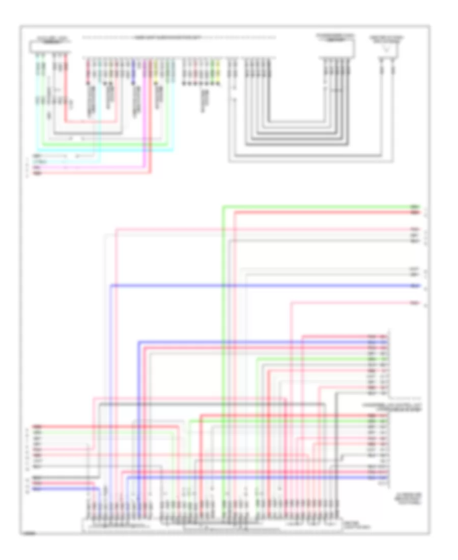
Navigation Wiring Diagram (4 of 4) for Honda CR-V LX 2014
List of elements for Navigation Wiring Diagram (4 of 4) for Honda CR-V LX 2014:
- A10
- A11
- A12
- A13
- A14
- A15
- A16
- A17
- A18
- A19
- A20
- A21
- A22
- A23
- A24
- A25
- A26
- A27
- A28
- A29
- A30
- A31
- A32
- Audio remote/multi-information display switch
- B10
- B11
- B12
- B13
- B14
- B15
- B16
- B17
- C108
- C109
- C111
- C112
- C113
- C118
- C119
- C146
- C17
- C18
- C19
- Cable reel (top of steering column)
- Ch+
- Ch-
- Computer data lines system
- Driver's door speaker
- Front passenger's door speaker
- Fuse 20a
- G502 (center of dash)
- G503 (under right center of dash)
- Hot at all times
- Info
- Left rear door speaker
- Left tweeter
- Menu
- Multi-information display unit
- Nca
- Pnk
- Red
- Right rear door speaker
- Right tweeter
- Source
- Stereo amplifier (under middle of dash)
- Subwoofer
- Under-hood fuse/relay box (on left side of engine compt)
- Usb port
- Vol down
- Vol up
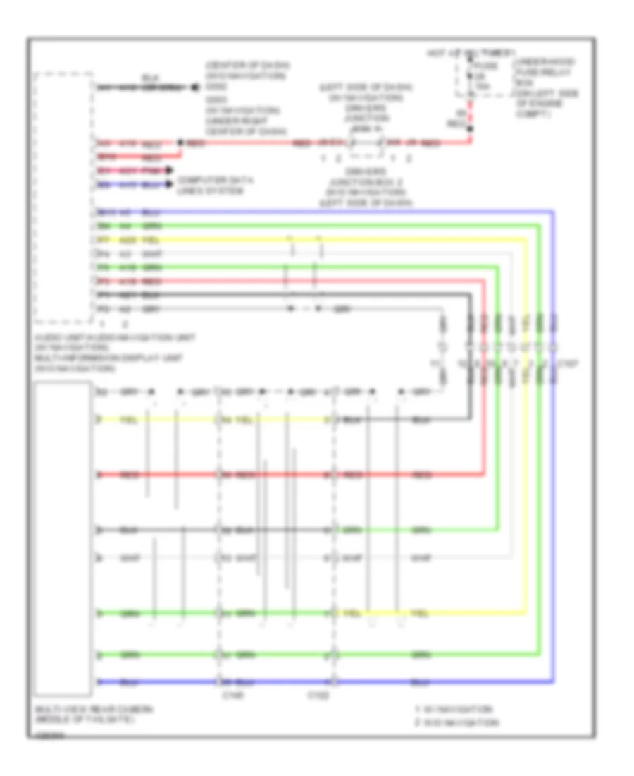
Rear Camera Wiring Diagram for Honda CR-V LX 2014
List of elements for Rear Camera Wiring Diagram for Honda CR-V LX 2014:
- (center of dash) (w/o navigation) g502
- (left side of dash) (w/ navigation) driver's junction box 1
- A10
- A15
- A16
- A18
- A19
- A20
- A21
- A31
- Audio unit/audio-navigation unit (w/ navigation) multi-informision display unit (w/o navigation)
- B10
- B15
- C122
- C145
- Computer data lines system
- Driver's junction box 2 (w/o navigation) (left side of dash)
- Fuse 10a
- G503 (w/ navigation) (under right center of dash)
- Hot at all times
- Multi-view rear camera (middle of tailgate)
- Pnk
- Red
- Under-hood fuse/relay box (on left side of engine compt)
- W/ navigation
- W/o navigation
POWER DISTRIBUTION
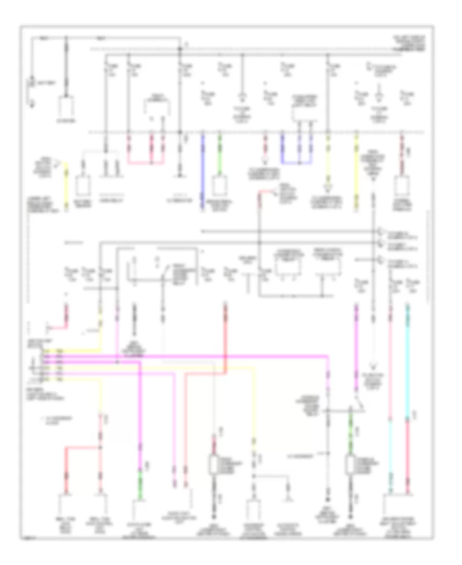
Power Distribution Wiring Diagram (1 of 4) for Honda CR-V LX 2014
List of elements for Power Distribution Wiring Diagram (1 of 4) for Honda CR-V LX 2014:
- & awd
- (if equipped) front fog light relay
- (on left side of engine compt) under-hood fuse/relay box
- (under left end of dash) under-dash fuse/relay box
- 100a
- 10a
- 15a
- 20a
- 60a
- 7.5a
- A24
- Alternator
- Audio unit/ audio navigation unit
- Automatic dimming inside mirror
- Battery
- Battery sensor
- Brake pedal position switch
- C103
- C108
- C110
- C112
- C114
- C117
- Console accessory power socket
- Console accessory power socket relay
- Driver's junction box 2 (left side of dash)
- Driver's micu
- Driver's power seat adjustment switch (w/ driver's power seat)
- Dvd player unit (w/ rear entertainment)
- From ignition switch (diagram 2 of 4)
- From under-hood fuse/relay box (diagram 3 of 4)
- Front accessory power socket
- Front accessory power socket relay
- Fuse
- Fuse 1-6
- Fuse 2-2
- Fuse 2-3
- G501 (behind instrument cluster)
- G503 (under right center of dash)
- Horn relay
- Ignition key switch
- Moonroof control unit/motor (w/ moonroof)
- Pgm-fi subrelay
- Pnk
- Q11
- Real time awd control unit (awd)
- Real time awd relay (awd)
- Rear window washer motor relay
- Red
- Starter
- Stereo amplifier (premium)
- T101
- To fuse 1-5 (diagram 3 of 4)
- To fuse 14 (diagram 3 of 4)
- To fuse 2-1 (diagram 3 of 4)
- To fuse 28 (diagram 4 of 4)
- To fuse 42 (diagram 3 of 4)
- To fuse 7 (diagram 2 of 4)
- To ignition switch (diagram 2 of 4)
- To under-dash fuse/relay box (diagram 2 of 4)
- To under-dash fuse/relay box (diagram 4 of 4)
- W/ moonroof
- Windshield washer motor relay
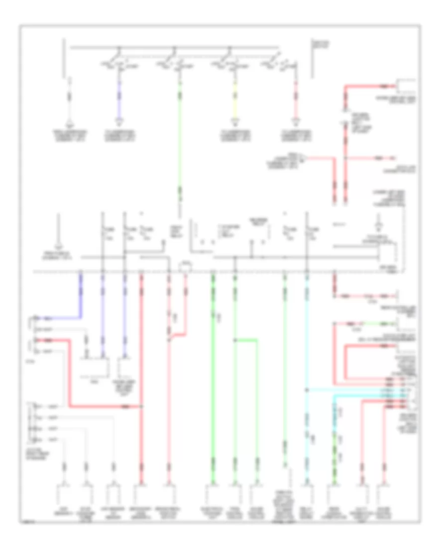
Power Distribution Wiring Diagram (2 of 4) for Honda CR-V LX 2014
List of elements for Power Distribution Wiring Diagram (2 of 4) for Honda CR-V LX 2014:
- (under left end of dash) under-dash fuse/relay box
- 10a
- 15a
- 7.5a
- A16
- Acc
- Automatic lighting/ sunlight sensor (if equipped)
- B17
- B28
- Brake pedal position switch
- C10
- C103
- C104
- C108
- C112
- C122
- C126
- C127
- C13
- C134
- C145
- Cmp sensor a
- D17
- Data link connector (dlc)
- Driver's junction box 1 (left side of dash)
- Driver's junction box 2 (left side of dash)
- Driver's micu
- Dvd player unit (exl w/ rear entertainment)
- Eld
- Electrical compass unit
- Evap canister purge valve
- From fuse 28 (diagram 1 of 4)
- From under-dash fuse/relay box (diagram 1 of 4)
- From under-hood g fuse/relay box (diagram 1 of 4)
- Fuse
- Gauge control module
- Ignition switch
- Immobilizer keyless control unit
- Immobilizer- keyless control unit
- J/c c136 (right rear of engine)
- Lock
- Maf sensor/ iat sensor
- Multi- information display unit
- P18
- Park pin switch/ shift lock solenoid/ a/t gear position indicator panel light
- Pcm
- Pgm-fi main relay
- Q16
- Rear controller & screen (exl)
- Rear window wiper motor
- Red
- Relay circuit board
- Reverse relay
- Secondary ho2s (sensor 2)
- Start
- Start on
- Starter cut relay
- To fuse 24 (diagram 4 of 4)
- To under-dash fuse/relay box (diagram 1 of 4)
- To under-dash fuse/relay box (diagram 4 of 4)
- Tpms control module
Power Distribution Wiring Diagram (3 of 4) for Honda CR-V LX 2014
List of elements for Power Distribution Wiring Diagram (3 of 4) for Honda CR-V LX 2014:
- (not used)
- (on left side of engine compt) under-hood fuse/relay box
- (under left end of dash) under-dash fuse/relay box
- (w/ seat heaters)
- 10a
- 15a
- 20a
- 30a
- 40a
- 50a
- 7.5a
- 70a
- A/c compressor clutch relay
- A/c condenser fan relay
- A16
- B13
- Blower motor relay
- C102
- C113
- C114
- C116
- C117
- C126
- Driver unlock relay
- Driver's seat heater relay (high)
- Driver's seat heater relay (low)
- Eld unit
- Eps control unit
- From fuse 12 (diagram 1 of 4)
- From fuse 16 (diagram 1 of 4)
- From fuse 2-3 (diagram 1 of 4)
- From fuse 27 l (diagram 1 of 4)
- Front passenger's seat heater relay (high)
- Front passenger's seat heater relay (low)
- Fuse
- Fuse 1-1
- Fuse 1-3
- Fuse 1-4
- Fuse 1-5
- Fuse 2-1
- Fuse 2-10
- Fuse 2-11
- Fuse 2-8
- Fuse 2-9
- Fuse 20a
- Ignition coil relay
- Left headlight low beam relay
- Lock relay
- Moonroof control unit/ motor (w/ moonroof)
- Pnk
- Power window master switch
- Power window relay
- Radiator fan relay
- Real time awd relay (awd)
- Red
- Relay circuit board
- Right headlight low beam relay
- Tailgate actuator relay
- Taillight relay
- To under-dash fuse/relay box (diagram 1 of 4)
- Unlock relay
- Vsa modulator control unit
- Windshield wiper motor relay
Power Distribution Wiring Diagram (4 of 4) for Honda CR-V LX 2014
List of elements for Power Distribution Wiring Diagram (4 of 4) for Honda CR-V LX 2014:
- (not used)
- (on left side of engine compt) under-hood fuse/relay box
- (under left end of dash) under-dash fuse/relay box
- 10a
- 15a
- 30a
- 7.5a
- A/c compressor clutch relay
- A11
- A38
- A39
- B1 pnk
- B30
- Blower motor relay
- C108
- C110
- C111
- C113
- C116
- C117
- C125
- C17
- D14
- D28
- D6 pnk
- Diode a
- Driver's junction box 2 (left side of dash)
- Driver's micu
- Driver's power lumbar support switch (w/ lumbar seats)
- Driver's seat heater switch (w/seat heaters)
- E5 pnk
- Eps control module
- Etcs control relay
- Except exl
- Exl
- Fan control relay
- From fuse 2-3 (diagram 1 of 4)
- From fuse 23 (diagram 2 of 4)
- From ignition switch (diagram 2 of 4)
- From under- hood fuse/ relay box (diagram 1 of 4)
- From under-dash fuse/relay box (diagram 4 of 4)
- Front passenger's air bag cutoff indicator
- Front passenger's seat heater switch (w/seat heaters)
- Fuse
- Fuse 2-4
- Fuse 2-6
- Hazard warning switch
- Hvac control unit/ climate control unit
- Interior light cut relay
- J8 pnk
- Ods unit
- P15
- Pgm-fi main relay 1
- Pnk
- Power mirror switch
- Radiator fan relay
- Rear window defogger relay
- Red
- Srs unit
- Steering angle sensor
- To driver's junction box 2 (diagram 4 of 4)
- Vsa modulator control module
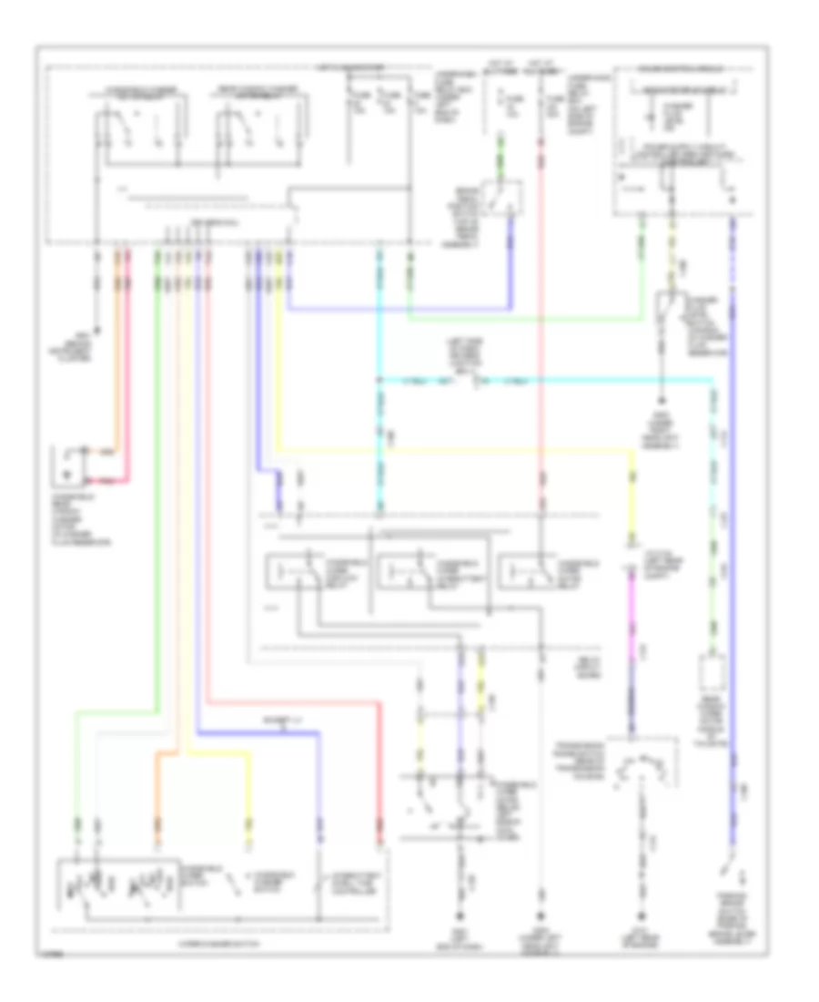
POWER DOOR LOCKS
Power Door Locks Wiring Diagram (1 of 2) for Honda CR-V LX 2014
List of elements for Power Door Locks Wiring Diagram (1 of 2) for Honda CR-V LX 2014:
- (behind instrument cluster) g501
- (bottom center of tailgate) tailgate release actuator/latch switch
- (top of left "d" pillar) g603
- (under right center of dash) g503
- B11
- B16
- B18
- B22
- B29
- B33
- B34
- B40
- C102
- C109
- C11
- C112
- C127
- C14
- C145
- C18
- C27
- D17
- D22
- Door lock knob
- Driver's door key cylinder switch
- Driver's door lock actuator/knob switch/ key cylinder switch (in driver's door)
- Driver's door lock knob switch
- Driver's micu
- Exterior lights system
- Front passenger's door lock actuator/knob switch (in front passenger's door)
- Fuse 10a
- Fuse 15a
- Fuse 20a
- G501 (behind instrument cluster)
- G603 (top of left "d" pillar)
- Headlights system
- Horns system
- Hot at all times
- Hot in on or start
- Key door lock knob
- Lock
- Lock relay
- N10
- N12
- Open
- P11
- Pnk
- Q10
- Q16
- Red
- Tailgate actuator relay
- Tailgate outer handle switch
- Under-dash fuse/relay box (under left end of dash)
- Unlock
- Unlock relay
- Unlock relay (dr)
- W10
- W23
- X10
Power Door Locks Wiring Diagram (2 of 2) for Honda CR-V LX 2014
List of elements for Power Door Locks Wiring Diagram (2 of 2) for Honda CR-V LX 2014:
- (center front of engine compt) (except lx) security hood switch
- (rear of transmission housing) transmission range switch
- 10v
- Antenna
- B-can h
- B-can l
- B-can transceiver
- C102
- C109
- C112
- C113
- C118
- C119
- C131
- Circuit
- Circuit stabilizing
- Close
- Computer data lines system
- Dc/dc converter
- Dlc (under left center of dash)
- Door ind
- Door lock knob
- Driver's door switch (in driver's "b" pillar)
- Driver's junction box 1 (left side of dash)
- Driver's junction box 2 (left side of dash)
- Exl w/o navigation & w/ res
- Front passenger's door switch (in front passenger's "b" pillar)
- Front passenger's power window switch
- Fuse 10a
- G101 (left rear of engine)
- G402 (left kick panel)
- G501 (behind instrument cluster)
- G502 (center of dash)
- G503 (under right center of dash)
- G601 (under driver's seat)
- G604 (right "d" pillar)
- Gauge control module
- Hot at all times
- Ignition key switch
- Immobilizer keyless control unit (on steering column, integral to ignition switch)
- Indicator drive
- J/c c134 (left rear of engine compt)
- Left rear door lock actuator/knob switch (in left rear door)
- Left rear door switch (in left rear "c" pillar)
- Lock
- Network controller
- Pnk
- Power window master switch
- R p
- Red
- Right rear door lock actuator/knob switch (in right rear door)
- Right rear door switch (in right rear "c" pillar)
- Security ind
- Sound systems
- Tailgate ind
- Under-hood fuse/relay box (on left side of engine compt)
- Unlock
POWER MIRRORS
Automatic Day/Night Mirror Wiring Diagram for Honda CR-V LX 2014
List of elements for Automatic Day/Night Mirror Wiring Diagram for Honda CR-V LX 2014:
- Audio unit/ audio navigation unit
- Automatic dimming inside mirror
- B21
- B25
- B45
- C112
- C114
- C121
- C131
- C134
- D21
- Driver's junction box 2 (left side of dash)
- Driver's micu
- Exterior lights system
- Fuse 5 10a
- Fuse 6 7.5a
- G101 (left rear of engine)
- G501 (behind instrument cluster)
- Hot in on or start
- Left backup light
- Moonroof control unit/motor (center rear of roof)
- Pcm (left side of engine compt)
- Pnk
- Q11
- Real time awd control unit (behind left rear quarterpanel)
- Real time awd relay (on rear relay holder)
- Red
- Reverse relay
- Tan
- Transmission range switch (rear of transmission housing)
- Under-dash fuse/relay box (under left end of dash)
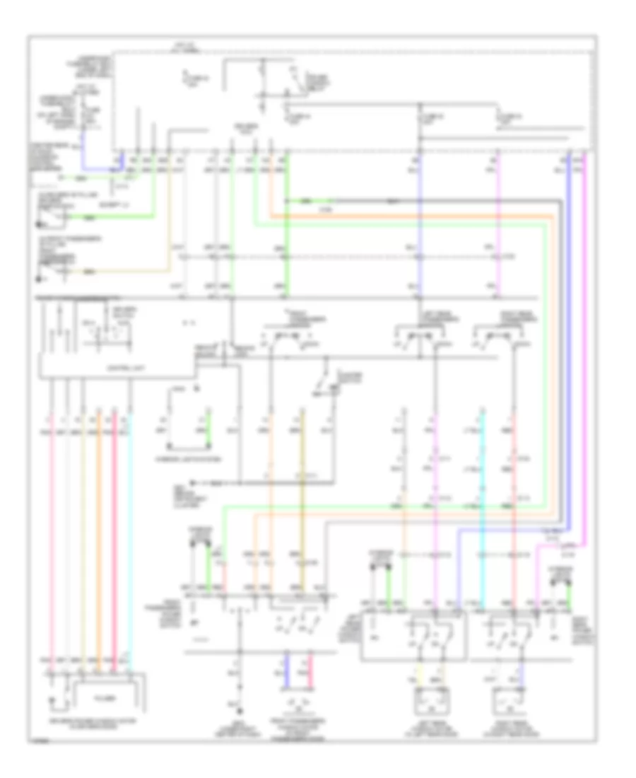
Power Mirrors Wiring Diagram for Honda CR-V LX 2014
List of elements for Power Mirrors Wiring Diagram for Honda CR-V LX 2014:
- C109
- C111
- Defogger (if equipped)
- Defogger system
- Down/ left
- Down/ right
- Driver's junction box 2 (left side of dash)
- Fuse 22 7.5a
- G501 (behind instrument cluster)
- Hot in on
- Interior lights system
- Left
- Left power mirror (in driver's door)
- Left/ right motor
- Pnk
- Power mirror switch
- Right
- Right power mirror (in front passenger's door)
- Under-dash fuse/relay box (under left end of dash)
- Up/ down motor
- Up/ left
- Up/ right
POWER SEATS
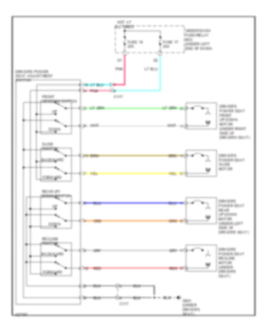
Driver Power Seat Wiring Diagram for Honda CR-V LX 2014
List of elements for Driver Power Seat Wiring Diagram for Honda CR-V LX 2014:
- Backward
- C117
- Down
- Driver's power seat adjustment switch
- Driver's power seat front up-down motor (under right side of driver's seat)
- Driver's power seat rear up-down motor (under left side of driver's seat)
- Driver's power seat recline motor (under driver's seat)
- Driver's power seat slide motor
- Forward
- Front up-down switch
- Fuse 16 20a
- Fuse 17 20a
- G601 (under driver's seat)
- Hot at all times
- Pnk
- Rear up/ down switch
- Recline switch
- Red
- Slide switch
- Under-dash fuse/relay box (under left end of dash)
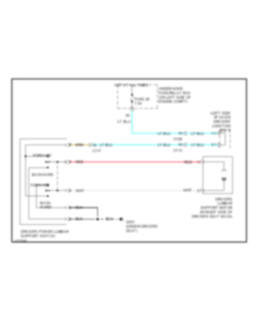
Driver"s Lumbar Wiring Diagram for Honda CR-V LX 2014
List of elements for Driver"s Lumbar Wiring Diagram for Honda CR-V LX 2014:
- (left side of dash) driver's junction box 2
- Back- ward
- Backward
- C108
- C113
- C117
- Driver's lumbar support motor (in right side of driver's seat back)
- Driver's power lumbar support switch
- Forward
- Fuse 28 7.5a
- G601 (under driver's seat)
- Hot at all times
- Red
- Under-hood fuse/relay box (on left side of engine compt)
Heated Seats Wiring Diagram for Honda CR-V LX 2014
List of elements for Heated Seats Wiring Diagram for Honda CR-V LX 2014:
- (under driver's seat) driver's seat heater relay (high)
- (under driver's seat) driver's seat heater relay (low)
- (under front passenger's seat) front passenger's seat heater relay (high)
- (under front passenger's seat) front passenger's seat heater relay (low)
- B13
- Back
- C110
- C113
- C116
- C117
- Cushion
- Driver's junction box 2 (left side of dash)
- Driver's seat heater
- Driver's seat heater switch
- Front passenger's seat heater
- Front passenger's seat heater switch
- Fuse 14 20a
- Fuse 22 7.5a
- G503 (under right center of dash)
- G602 (under front passenger's seat)
- High
- High indicator
- Hot at all times
- Hot in on
- Illumination
- Indicator
- Interior lights system
- Low
- Low indicator
- Pnk
- Red
- Under-dash fuse/relay box (under left end of dash)
POWER TOP/SUNROOF
Power Top/Sunroof Wiring Diagram for Honda CR-V LX 2014
List of elements for Power Top/Sunroof Wiring Diagram for Honda CR-V LX 2014:
- A26
- Auto close
- Auto open
- B29
- B40
- C105
- C114
- Close
- Cpu
- Driver's door switch (in driver's "b" pillar)
- Driver's junction box 2 (left side of dash)
- Driver's micu
- Front passenger's door switch (in front passenger's "b" pillar)
- Fuse 11 20a
- Fuse 6 7.5a
- G501 (behind instrument cluster)
- Hall sensor
- Hot at all times
- Hot in on or start
- Input circuit
- Interior lights system
- Map light switch
- Mirrors system
- Moonroof close relay
- Moonroof motor
- Moonroof motor/ control unit (center rear of roof)
- Moonroof open relay
- Moonroof switch
- Off
- Open
- Pcm (left side of engine compt)
- Pnk
- Q11
- Rcv
- Red
- Tilt
- Under-dash fuse/relay box (under left end of dash)
POWER WINDOWS
Power Windows Wiring Diagram for Honda CR-V LX 2014
List of elements for Power Windows Wiring Diagram for Honda CR-V LX 2014:
- (center rear of roof) moonroof control unit/motor
- (in driver's "b" pillar) driver's door switch
- (in front passenger's "b" pillar) front passenger's door switch
- B19
- B29
- B40
- C102
- C109
- C111
- C112
- C113
- C114
- C118
- C119
- Control unit
- Down
- Driver's micu
- Driver's power window motor (in driver's door)
- Driver's switch
- Except lx
- Front passenger's power window switch
- Front passenger's switch
- Front passenger's window motor (in front passenger's door)
- Fuse 2-2 60a
- Fuse 42 20a
- Fuse 43 20a
- Fuse 44 20a
- Fuse 45 20a
- G501 (behind instrument cluster)
- G503 (under right center of dash)
- Hot at all times
- Interior lights system
- Left rear passenger's switch
- Left rear power window switch
- Left rear window motor (in left rear door)
- Master switch
- Off
- Pnk
- Power window master switch
- Power window relay
- Pulser
- Red
- Remote lock
- Remote unlock
- Right rear passenger's switch
- Right rear power window switch
- Right rear window motor (in right rear door)
- Under-dash fuse/relay box (under left end of dash)
- Under-hood fuse/relay box (on left side of engine compt)
RADIO
Base Radio Wiring Diagram (1 of 2) for Honda CR-V LX 2014
List of elements for Base Radio Wiring Diagram (1 of 2) for Honda CR-V LX 2014:
- (left rear of engine)
- (left side of engine compt) pcm
- A10
- A11
- A12
- A13
- A14
- A15
- A16
- A17
- A18
- A19
- A20
- A21
- A22
- A23
- A24
- Am/fm/xm antenna
- Audio unit/audio- navigation unit
- Automatic dimming inside mirror
- Auxiliary jack assembly
- B10
- B11
- B12
- B13
- B14
- B15
- B16
- B17
- B18
- B19
- B20
- B25
- C10
- C107
- C11
- C110
- C114
- C12
- C122
- C13
- C131
- C134
- C14
- C143
- C15
- C16
- Center junction box
- Computer data lines system
- D17
- D21
- Driver's junction box 2 (left side of dash)
- Driver's micu
- Electrical compass unit (left rear of roof)
- Fuse 10a
- Fuse 2-2 60a
- Fuse 7.5a
- G101
- G503 (under right center of dash)
- H10
- Hot at all times
- Hot in acc or on
- Hot in on or start
- Nca
- Pnk
- Q14
- Q16
- Red
- Reverse relay
- Sub amplifier
- Tan
- Transmission range switch (rear of transmission housing)
- Under-dash fuse/ relay box (under left end of dash)
- Under-hood fuse/relay box (on left side of engine compt)
Base Radio Wiring Diagram (2 of 2) for Honda CR-V LX 2014
List of elements for Base Radio Wiring Diagram (2 of 2) for Honda CR-V LX 2014:
- (left side of dash) driver's junction box 2
- (under left center of dash) tpms control unit
- A10
- A11
- A12
- A13
- A14
- A15
- A16
- A17
- A18
- A19
- A20
- A21
- A22
- A23
- A24
- A25
- A26
- A27
- A28
- A29
- A30
- A31
- A32
- Audio remote/multi-information display switch
- C109
- C111
- C112
- C113
- C118
- C119
- C121
- C146
- C17
- C18
- C19
- Cable reel (top of steering column)
- Center junction box
- Ch+
- Ch-
- Computer data lines system
- Driver's door speaker
- Front passenger's door speaker
- G10
- G502 (center of dash)
- Handsfree link control unit (under middle of dash)
- Info
- Left backup light
- Left rear door speaker
- Menu
- Multi-information display unit
- Navigation system
- Nca
- Pnk
- Red
- Right rear door speaker
- Source
- Usb port
- Vol down
- Vol up
Premium Radio Wiring Diagram, with Navigation (1 of 4) for Honda CR-V LX 2014
List of elements for Premium Radio Wiring Diagram, with Navigation (1 of 4) for Honda CR-V LX 2014:
- (behind right kick panel) xm receiver
- (under right center of dash) g503
- A10
- A11
- A12
- A13
- A14
- A15
- A16
- A17
- A18
- A19
- A20
- A21
- A22
- A23
- A24
- Am/fm/xm antenna
- Audio unit/ audio-navigation unit
- Automatic dimming inside mirror
- B10
- B11
- B12
- B13
- B14
- B15
- B16
- B17
- B18
- B19
- B20
- B21
- C10
- C11
- C114
- C12
- C13
- C134
- C14
- C142
- C143
- C15
- C16
- Computer data lines system
- D17
- D21
- Driver's junction box 1 (left side of dash)
- Driver's micu
- Fm distributor
- Fuse 10a
- Fuse 7.5a
- G503 (under right center of dash)
- Hot at all times
- Hot in on or acc
- Hot in on or start
- Navigation system
- Nca
- Pnk
- Q14
- Red
- Reverse relay
- Sub amplifier
- Tan
- Under-dash fuse/ relay box (under left end of dash)
- Under-hood fuse/relay box (on left side of engine compt)
Premium Radio Wiring Diagram, with Navigation (2 of 4) for Honda CR-V LX 2014
List of elements for Premium Radio Wiring Diagram, with Navigation (2 of 4) for Honda CR-V LX 2014:
- (left side of dash) driver's junction box 2
- (left side of engine compt) pcm
- (rear of transmission housing) transmission range switch
- (under middle of dash) stereo amplifier
- A10
- A11
- A12
- A13
- A14
- A15
- A16
- A17
- A18
- A19
- A20
- A21
- A22
- A23
- A24
- A26
- B25
- C105
- C112
- C114
- C121
- C131
- Driver's junction box 2 (left side of dash)
- G101 (left rear of engine)
- Left backup light
- Moonroof control unit/motor (center rear of roof)
- Pnk
- Red
- Right backup light
- Tan
- Tpms control unit (under left center of dash)
Premium Radio Wiring Diagram, with Navigation (3 of 4) for Honda CR-V LX 2014
List of elements for Premium Radio Wiring Diagram, with Navigation (3 of 4) for Honda CR-V LX 2014:
- (center of dash) gps antenna
- (passenger's dash) usb port
- A10
- A11
- A12
- A13
- Audio unit/audio-navigation unit
- Auxiliary jack assembly
- C110
- Center junction box
- Computer data lines system
- E10
- E11
- E12
- E13
- E14
- E15
- E16
- G10
- H10
- Handsfree link control unit (under middle of dash)
- Lines system computer data
- Navigation system
- Nca
- Pnk
- Red
- System navigation
- Xm receiver (behind right kick panel)
Premium Radio Wiring Diagram, with Navigation (4 of 4) for Honda CR-V LX 2014
List of elements for Premium Radio Wiring Diagram, with Navigation (4 of 4) for Honda CR-V LX 2014:
- A10
- A11
- A12
- A13
- A14
- A15
- A16
- A17
- A18
- A19
- A20
- A21
- A22
- A23
- A24
- A25
- A26
- A27
- A28
- A29
- A30
- A31
- A32
- Audio remote/multi-information display switch
- B10
- B11
- B12
- B13
- B14
- B15
- B16
- B17
- C108
- C109
- C111
- C112
- C113
- C118
- C119
- C146
- C17
- C18
- C19
- Cable reel (top of steering column)
- Ch+
- Ch-
- Computer data lines system
- Driver's door speaker
- Front passenger's door speaker
- Fuse 20a
- G502 (center of dash)
- G503 (under right center of dash)
- Hot at all times
- Info
- Left rear door speaker
- Left tweeter
- Menu
- Multi-information display unit
- Nca
- Pnk
- Red
- Right rear door speaker
- Right tweeter
- Source
- Stereo amplifier (under middle of dash)
- Subwoofer
- Under-hood fuse/relay box (on left side of engine compt)
- Usb port
- Vol down
- Vol up
Premium Radio Wiring Diagram, without Navigation (1 of 4) for Honda CR-V LX 2014
List of elements for Premium Radio Wiring Diagram, without Navigation (1 of 4) for Honda CR-V LX 2014:
- (behind right kick panel) xm receiver
- (left side of dash) driver's junction box 2
- A10
- A11
- A12
- A13
- A14
- A15
- A16
- A17
- A18
- A19
- A20
- A21
- A22
- A23
- A24
- Am/fm/xm antenna
- Audio unit/ audio-navigation unit
- B10
- B11
- B12
- B13
- B14
- B15
- B16
- B17
- B18
- B19
- B20
- C10
- C11
- C12
- C13
- C134
- C14
- C142
- C143
- C15
- C16
- Computer data lines system
- D17
- D21
- Driver's micu
- Fuse 10a
- Fuse 2-2 60a
- Fuse 7.5a
- G503 (under right center of dash)
- Gauge control module
- Hot at all times
- Hot in acc or on
- Hot in on or start
- Nca
- Pnk
- Q14
- Q16
- Red
- Reverse relay
- Sub amplifier
- Tan
- Under-dash fuse/ relay box (under left end of dash)
- Under-hood fuse/relay box (on left side of engine compt)
Premium Radio Wiring Diagram, without Navigation (2 of 4) for Honda CR-V LX 2014
List of elements for Premium Radio Wiring Diagram, without Navigation (2 of 4) for Honda CR-V LX 2014:
- (behind instrument cluster)
- (left rear of roof) electrical compass unit
- C103
- C104
- C107
- C110
- C114
- C122
- Dvd player unit
- Fuse 7.5a
- G501
- Hot at all times
- Moonroof switch
- Of dash)
- Pnk
- Rear controller & screen
- Red
- Tan
- Under- dash fuse/ relay box (under left end
Premium Radio Wiring Diagram, without Navigation (3 of 4) for Honda CR-V LX 2014
List of elements for Premium Radio Wiring Diagram, without Navigation (3 of 4) for Honda CR-V LX 2014:
- (left side of dash) driver's junction box 2
- (left side of engine compt) pcm
- (rear of transmission housing) transmission range switch
- (under left center of dash) tpms control unit
- (under middle of dash) stereo amplifier
- A10
- A11
- A12
- A13
- A14
- A15
- A16
- A17
- A18
- A19
- A20
- A21
- A22
- A23
- A24
- Audio unit/ audio-navigation unit
- Automatic dimming inside mirror
- B25
- C112
- C114
- C121
- C131
- Center junction box
- E10
- G10
- G101 (left rear of engine)
- H10
- Handsfree link control unit (under middle of dash)
- Left backup light
- Pnk
- Red
- Tan
- Xm receiver (behind right kick panel)
Premium Radio Wiring Diagram, without Navigation (4 of 4) for Honda CR-V LX 2014
List of elements for Premium Radio Wiring Diagram, without Navigation (4 of 4) for Honda CR-V LX 2014:
- A10
- A11
- A12
- A13
- A14
- A15
- A16
- A17
- A18
- A19
- A20
- A21
- A22
- A23
- A24
- A25
- A26
- A27
- A28
- A29
- A30
- A31
- A32
- Audio remote/multi-information display switch
- B10
- B11
- B12
- B13
- B14
- B15
- B16
- B17
- C108
- C109
- C111
- C112
- C113
- C118
- C119
- C146
- C17
- C18
- C19
- Cable reel (top of steering column)
- Ch+
- Ch-
- Computer data lines system
- Driver's door speaker
- Front passenger's door speaker
- Fuse 13 20a
- G502 (center of dash)
- G503 (under right center of dash)
- Hot at all times
- Info
- Left rear door speaker
- Left tweeter
- Menu
- Multi-information display unit
- Navigation system
- Nca
- Pnk
- Red
- Right rear door speaker
- Right tweeter
- Source
- Stereo amplifier (under middle of dash)
- Subwoofer
- Under-hood fuse/relay box (on left side of engine compt)
- Usb port
- Vol down
- Vol up
SHIFT INTERLOCK
Shift Interlock Wiring Diagram for Honda CR-V LX 2014
List of elements for Shift Interlock Wiring Diagram for Honda CR-V LX 2014:
- A13
- A21
- A28
- A29
- A35
- A36
- A45
- A46
- App sensor a
- App sensor b app sensor (top of accelerator pedal assembly)
- B24
- Brake pedal position switch (top of brake pedal assembly)
- C10
- C105
- C13
- C131
- C134
- C16
- C20
- D11
- D22
- Driver's micu
- Fuse 10a
- Fuse 15a
- Fuse 16 10a
- Fuse 7.5a
- G101 (left rear of engine)
- G502 (center of dash)
- Hot at all times
- Hot in acc or on
- Hot in on or start
- Ignition key switch
- Interior lights system
- Key interlock solenoid
- P10
- P11
- Park pin switch/ shift lock solenoid/ a/t gear position indicator panel light (park pin switch: base of shift lever assembly)
- Pcm (left side of engine compt)
- Pnk
- Power distribution system
- Transmission range switch (rear of transmission housing)
- Under-dash fuse/relay box (under left end of dash)
- Under-hood fuse/relay box (on left side of engine compt)
STARTING/CHARGING
Charging Wiring Diagram for Honda CR-V LX 2014
List of elements for Charging Wiring Diagram for Honda CR-V LX 2014:
- 12v
- A34
- Alternator
- B16
- B17
- Battery
- Battery sensor
- Brake pedal position switch (top of brake pedal assembly)
- C126
- C133
- C134
- Can-h
- Can-l
- Charging system ind
- Computer data lines system
- D17
- Dc/dv converter
- Driver's junction box 2 (left side of dash)
- Driver's micu
- Eld unit
- Fast controller area network transceiver
- Fuse 1-6 100a
- Fuse 10a
- Fuse 14 10a
- Fuse 2-1 50a
- Fuse 29 10a
- G1 (under battery tray)
- G302 (under left headlight assembly)
- Gauge control module
- Hot in on or start
- Ignition switch
- Indicator drive circuit
- Junction connector c136 (right rear of engine)
- Pcm (left side of engine compt)
- Q16
- Red
- Starting circuit
- T101
- Tan
- Under-dash fuse/relay box (under left end of dash)
- Under-hood fuse/relay box (on left side of engine compt)
- W/o navigation w/ rear entertainment system
Starting Wiring Diagram for Honda CR-V LX 2014
List of elements for Starting Wiring Diagram for Honda CR-V LX 2014:
- Acc
- Battery
- Battery sensor
- C131
- C137
- D32
- Diode c (left kick panel)
- Fuse 1-6 100a
- Fuse 11 7.5a
- Fuse 2-1 50a
- G1 (under battery tray)
- G101 (left rear of engine)
- G402 (left kick panel)
- Ignition switch
- Junction connector c134 (left rear of engine compt)
- Lock
- Magnetic switch
- Red
- Run
- Start
- Starter
- Starter cut relay
- Starter motor
- Transmission range switch (rear of transmission housing)
- Under-dash fuse/relay box (under left end of dash)
- Under-hood fuse/relay box (on left side of engine compt)
SUPPLEMENTAL RESTRAINTS
Supplemental Restraints Wiring Diagram (1 of 4) for Honda CR-V LX 2014
List of elements for Supplemental Restraints Wiring Diagram (1 of 4) for Honda CR-V LX 2014:
- (under left front of center console) g504
- A10
- A11
- A12
- A13
- A14
- A15
- A16
- A17
- A18
- A19
- A20
- A21
- A22
- A23
- A24
- A25
- A26
- A27
- A28
- A29
- A30
- A31
- A32
- A33
- A34
- A35
- A36
- A37
- A38
- A39
- B30
- C101
- C116
- C125
- Cable reel (top of steering column)
- Computer data lines system
- Driver's air bag inflator (in steering wheel)
- Front passenger's air bag inflator (behind glove box)
- Fuse 10a
- Fuse 7.5a
- Hot in on or start
- Left front impact sensor (left front corner of engine compt)
- Pnk
- Rear entertainment system
- Red
- Right front impact sensor (right front corner of engine compt)
- Srs unit (under front of center console)
- Under-dash fuse/relay box (under left end of dash)
- W/ navigation & w/o rear entertainment system
- W/o navigation &
- W/o navigation & w/ rear entertainment system
Supplemental Restraints Wiring Diagram (2 of 4) for Honda CR-V LX 2014
List of elements for Supplemental Restraints Wiring Diagram (2 of 4) for Honda CR-V LX 2014:
- (left side of front passenger's seat back) ods unit
- C116
- C125
- Front passenger's weight sensor (front inner side) (under front inner side of front passenger's seat)
- Front passenger's weight sensor (front outer side) (under front outer side of front passenger's seat)
- Front passenger's weight sensor (rear inner side) (under rear inner side of front passenger's seat)
- Front passenger's weight sensor (rear outer side) (under rear outer side of front passenger's seat)
- G602 (under front passenger's seat)
- Nca
- Opds sensor
- Pnk
- Rear entertainment system
- Red
- W/ navigation & w/o rear entertainment system
- W/o navigation &
- W/o navigation & w/ rear entertainment system
Supplemental Restraints Wiring Diagram (3 of 4) for Honda CR-V LX 2014
List of elements for Supplemental Restraints Wiring Diagram (3 of 4) for Honda CR-V LX 2014:
- (base of driver's "b" pillar) driver's seat belt tensioner
- (in driver's seat belt buckle assembly) driver's seat belt buckle switch
- (in front passenger's seat belt buckle assembly) front passenger's seat belt buckle switch
- C116
- Computer data lines system
- D17
- Dc/dc converter
- Driver's junction box 2 (left side of dash)
- Driver's micu
- F-can h
- F-can l
- F-can transceiver
- Fail-safe circuit
- Forced turning-on circuit
- Front passenger's air bag cut-off indicator
- Fuse 10a
- G502 (center of dash)
- G601 (under driver's seat)
- G602 (under front passenger's seat)
- Gauge control module
- Hot at all times
- Hot in on or start
- Illumination control
- Indicator driver circuit
- Interior lights system
- Pnk
- Q16
- Red
- Seat belt reminder ind
- Side air bag cut-off ind
- Srs ind
- Under-dash fuse/relay box (under left end of dash)
- Under-hood fuse/relay box (on left side of engine compt)
- W/ navigation & w/o rear entertainment system
- W/o navigation & w/ rear entertainment system
Supplemental Restraints Wiring Diagram (4 of 4) for Honda CR-V LX 2014
List of elements for Supplemental Restraints Wiring Diagram (4 of 4) for Honda CR-V LX 2014:
- (base of front passenger's "b" pillar) front passenger's seat belt tensioner
- (outer edge of driver's seat back) driver's side air bag inflator
- (outer edge of front passenger's seat back) front passenger's side air bag inflator
- (top of left "d" pillar) left side curtain air bag inflator
- (top of right "d" pillar) right side curtain air bag inflator
- (under front of center console)
- B10
- B11
- B12
- B13
- B14
- B15
- B16
- B17
- B18
- B19
- B20
- B21
- B22
- B23
- B24
- B25
- B26
- B27
- B28
- B29
- B30
- B31
- B32
- B33
- B34
- B35
- B36
- B37
- B38
- B39
- C115
- C117
- C124
- Driver seat position sensor (under left rear of driver's seat)
- G602 (under front passenger's seat)
- Left side impact sensor (first) (base of left "b" pillar)
- Left side impact sensor (second) (in left "c" pillar)
- Pnk
- Rear entertainment system
- Rear safing sensor (under center of rear seats)
- Red
- Right side impact sensor (first) (base of right "b" pillar)
- Right side impact sensor (second) (in right "c" pillar)
- Srs unit
- W/ navigation & w/o rear entertainment system
- W/o navigation &
- W/o navigation & w/ rear entertainment system
TRANSMISSION
A/T Wiring Diagram (1 of 2) for Honda CR-V LX 2014
List of elements for A/T Wiring Diagram (1 of 2) for Honda CR-V LX 2014:
- (left side of transmission housing)
- 2nd clutch transmission fluid pressure switch a (top of transmission housing)
- 3rd clutch transmission fluid pressure switch a (left rear of transmission housing)
- A/t clutch pressure control solenoid valve a (top of transmission housing)
- A/t clutch pressure control solenoid valve b
- A/t clutch pressure control solenoid valve c
- A13
- A14
- A21
- A28
- A29
- A35
- A36
- A45
- A46
- B11
- B19
- B21
- B23
- B24
- B25
- B26
- B27
- B28
- B29
- B31
- B32
- B35
- B36
- B38
- B39
- B40
- B44
- B45
- B48
- Brake pedal position switch (top of brake pedal assembly)
- C105
- C130
- C16
- C21
- C23
- C24
- C32
- Computer data lines system
- D11
- D17
- D22
- Driver's micu
- Ex-l
- Fuse 10a
- Fuse 7.5a
- G101 (left rear of engine)
- G502 (center of dash)
- Hot at all times
- Hot in on or start
- Park pin switch/shift lock solenoid/a/t gear position indicator panel light (base of shift lever assembly)
- Pcm (left side of engine compt)
- Pnk
- Q16
- Red
- Shift control solenoid valves (left side of transmission housing)
- Tan
- Under-dash fuse/relay box (under left end of dash)
- Under-hood fuse/relay box (on left side of engine compt)
A/T Wiring Diagram (2 of 2) for Honda CR-V LX 2014
List of elements for A/T Wiring Diagram (2 of 2) for Honda CR-V LX 2014:
- (left side of dash) driver's junction box 2
- (rear of transmission housing) transmission range switch
- 10v stabilizing circuit
- A/t gear position dimming circuit
- A/t gear position indicator drive circuit
- App sensor (top of accelerator pedal assembly)
- App sensor a
- App sensor b
- Atf temperature sensor (bottom left side of transmission housing)
- C130
- C131
- C134
- Computer data lines system
- Dc/dc converter
- F-can transceiver
- F-canh
- F-canl
- G101 (left rear of engine)
- G502 (center of dash)
- Gauge control module
- Indicator drive circuit
- Input shaft (mainshaft) speed sensor (right side of transmission housing)
- J/c c136 (right rear of engine)
- Map sensor (on throttle body)
- Output shaft (countershaft) speed sensor (right rear of transmission housing)
- Pnk
- Red
- Starting/ charging system
- Tan
AWD Wiring Diagram for Honda CR-V LX 2014
List of elements for AWD Wiring Diagram for Honda CR-V LX 2014:
- (left side of dash) driver's junction box 2
- (on rear relay holder) real time awd relay
- Awd ind
- C112
- C123
- C126
- C129
- Computer data lines system
- D17
- Dc/dc converter
- Ex-l
- Fuse 1-5 30a
- Fuse 10a
- Fuse 7.5a
- G502 (center of dash)
- G603 (top of left "d" pillar)
- Gauge control module
- Hot at all times
- Hot in on or start
- Indicator drive circuit
- Pcm (left side of engine compt)
- Pnk
- Pressure sensor
- Q11
- Q16
- Real time awd control unit (behind left rear quarterpanel)
- Rear differential assembly (on differential assembly)
- Rear differential pump motor
- Rear differential solenoid valve
- Rear differential temperature sensor
- Red
- Sensor fluid pressure rear differential
- Tan
- Transceiver f-can
- Under-dash fuse/relay box (under left end of dash)
- Under-hood fuse/relay box (on left side of engine compt)
TRUNK, TAILGATE, FUEL DOOR
Tailgate Release Wiring Diagram for Honda CR-V LX 2014
List of elements for Tailgate Release Wiring Diagram for Honda CR-V LX 2014:
- (center of dash) g502
- (top of left "d" pillar) g603
- B-can transceiver
- B22
- C112
- C127
- C145
- Circuit ind drive
- Computer data lines system
- Driver's micu
- Fuse 41 20a
- Fuse 5 10a
- G501 (behind instrument cluster)
- G603 (top of left "d" pillar)
- Gauge control module
- H b-can
- Hot at all times
- Hot in on or start
- L b-can
- Latch switch
- Network controller controller area power suply circuit/
- P16
- Pnk
- Red
- Release actuator
- Tailgate actuator relay
- Tailgate ind
- Tailgate outer handle switch
- Tailgate release actuator/ latch switch (bottom center of tailgate)
- Under-dash fuse/relay box (under left end of dash)
- W23
WARNING SYSTEMS
Chime Wiring Diagram for Honda CR-V LX 2014
List of elements for Chime Wiring Diagram for Honda CR-V LX 2014:
- (in right "c" pillar)
- 0) off 1) park 2) auto 3) head
- 5v on/off
- A13
- A20
- A21
- Amp
- B-can transceiver
- B22
- B24
- B29
- B33
- B34
- B40
- Brake fluid level switch (on brake fluid reservoir)
- Brake indicator
- C108
- C116
- Can h
- Can l
- Circuit
- Circuit 5v control
- Circuit dimming
- Combination light switch
- Computer data lines system
- Converter dc/dc
- D11
- D17
- Door indicator
- Driver's door switch (in driver's "b" pillar)
- Driver's junction box 2 (left side of dash)
- Driver's micu
- Driver's seat belt buckle switch (in driver's seat belt buckle assembly)
- Except lx
- Exl
- F-can transceiver
- Fail-safe circuit
- Front passenger's door switch (in front passenger's "b" pillar)
- Front passenger's seat belt buckle switch (in front passenger's seat belt buckle assembly)
- Fuse 10a
- Fuse 7.5a
- G402 (left kick panel)
- G502 (center of dash)
- G601 (under driver's seat)
- G602 (under front passenger's seat)
- Gauge control module
- Headlight switch
- Hot at all times
- Hot in acc or on
- Hot in on or start
- Ignition key switch
- Indicator drive circuit
- Left rear door switch (in left "c" pillar)
- Lights on indicator
- Low oil pressure indicator
- Mixing
- Oil pressure switch (on right front of engine, above oil filter)
- P11
- Parking brake switch (base of parking brake lever assembly)
- Pcm (left side of engine compt)
- Pnk
- Q16
- Red
- Right rear door switch
- Seat belt reminder indicator
- Speaker
- Srs unit (under front of center console)
- Stabilizing 10v
- Tailgate indicator
- Turning-on forced
- Under- dash fuse/ relay box (under left end of dash)
- Under- hood fuse/ relay box (on left side of engine compt)
- W/ res
Tire Pressure Monitoring Wiring Diagram for Honda CR-V LX 2014
List of elements for Tire Pressure Monitoring Wiring Diagram for Honda CR-V LX 2014:
- Can h
- Can l
- Computer data lines system
- Converter dc/dc
- D17
- Driver's junction box 2 (left side of dash)
- Driver's micu
- F-can transceiver
- Fuse 10a
- G501 (behind instrument cluster)
- G502 (center of dash)
- Gauge control module
- Hot at all times
- Hot in on or start
- Indicator drive circuit
- Interior lights system
- Low tire pressure indicator
- Q16
- Red
- Tpms indicator
- Tpms switch
- Under-dash fuse/relay box (under left end of dash)
- Under-hood fuse/relay box (on left side of engine compt)
- W/ res
WIPER/WASHER
Front Wiper/Washer Wiring Diagram for Honda CR-V LX 2014
List of elements for Front Wiper/Washer Wiring Diagram for Honda CR-V LX 2014:
- (left side of dash) driver's junction box 2
- A12
- A13
- A16
- Brake pedal position switch (top of brake pedal assembly)
- C108
- C112
- C127
- C131
- C139
- C145
- C15
- C16
- C22
- C23
- C32
- D22
- Driver's micu
- Except lx
- Fuse 10a
- Fuse 15a
- Fuse 2-9 30a
- G101 (left rear of engine)
- G202 (under right headlight assembly)
- G302 (under left headlight assembly)
- G401 (left end of dash)
- G501 (behind instrument cluster)
- Gauge control module
- Hi windshield wiper motor (below left side of cowl cover)
- High
- Hot at all times
- Hot in on or start
- Indicator drive circuit
- Int low
- Intermittent dwell time controller
- J/c c134 (left rear of engine compt)
- Mist
- Off
- Parking brake switch (base of parking brake lever assembly)
- Pnk
- Rear window washer motor relay
- Rear window wiper motor (middle of tailgate)
- Red
- Relay circuit board
- T15
- T16
- T17
- T18
- T19
- Transmission range switch (rear of transmission housing)
- Under-dash fuse/ relay box (under left end of dash)
- Under-hood fuse/ relay box (on left side of engine compt)
- Washer fluid level ind
- Washer fluid level switch (canada) (in washer fluid reservoir)
- Windshield washer motor relay
- Windshield washer switch
- Windshield wiper high/low relay
- Windshield wiper intermittent relay
- Windshield wiper motor relay
- Windshield wiper switch
- Windshield/ rear window washer motor (in washer fluid reservoir)
- Wiper/washer switch
Rear Wiper/Washer Wiring Diagram for Honda CR-V LX 2014
List of elements for Rear Wiper/Washer Wiring Diagram for Honda CR-V LX 2014:
- A13
- Brake pedal position switch (top of brake pedal assembly)
- C112
- C127
- C131
- C145
- C15
- C16
- D11
- D21
- Driver's micu
- Front wiper/ washer circuit
- Fuse 10a
- Fuse 15a
- G101 (left rear of engine)
- G501 (behind instrument cluster)
- G603 (top of left "d" pillar)
- Hot at all times
- Hot in on or start
- Int
- J/c c134 (left rear of engine compt)
- Off
- Off int
- Pcm (left side of engine compt)
- Pnk
- Rear window washer motor relay
- Rear window wiper motor (middle of tailgate)
- Rear wiper washer switch
- Red
- Reverse relay
- T10
- T15
- T20
- Tan
- Transmission range switch (rear of transmission housing)
- Under-dash fuse/ relay box (under left end of dash)
- Under-hood fuse/ relay box (on left side of engine compt)
- Wash
- Windshield washer motor relay
- Windshield/ rear window washer motor (in washer fluid reservoir)
- Wiper/washer switch

 Čeština
 Dansk
Dansk Deutsch
 Ελληνικά
 English
 English
 Español
 Suomi
Suomi Français
 Français
 עברית
עברית Hrvatski
 Magyar
 日本語
日本語 한국어
한국어 Nederlands
 Polski
 Português
 Português
 Română
 Русский
 Slovenčina
 Slovenščina
 Svenska
 Türkçe
 中文 (中国)