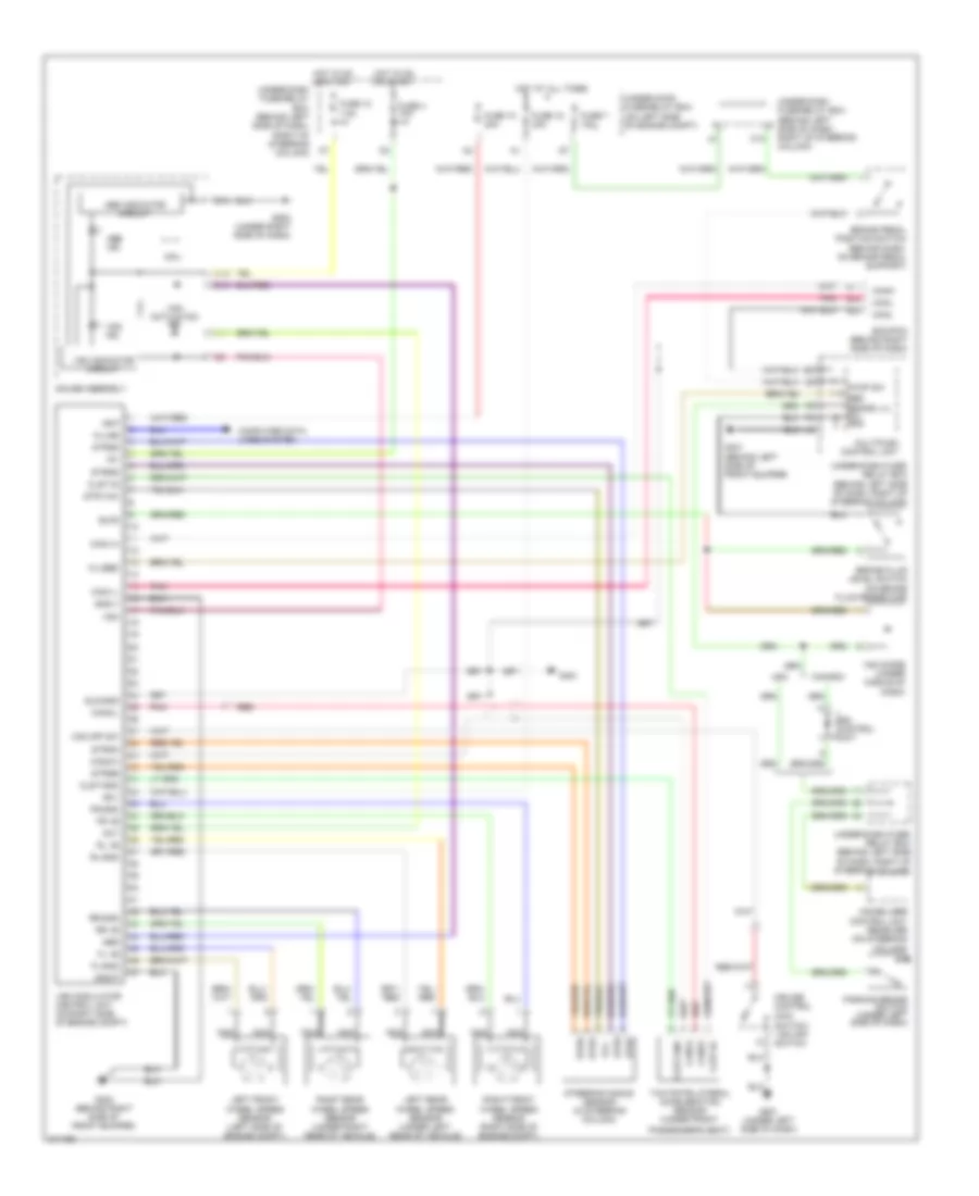
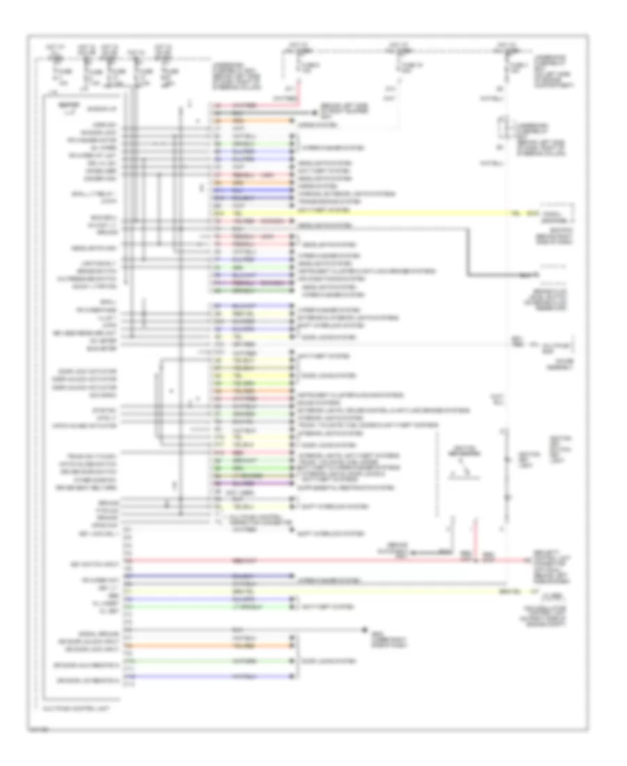
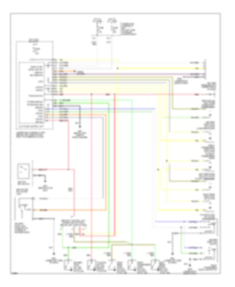
AIR CONDITIONING
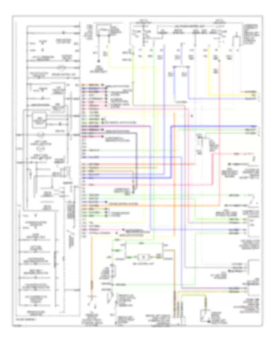
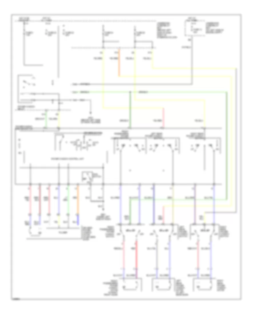
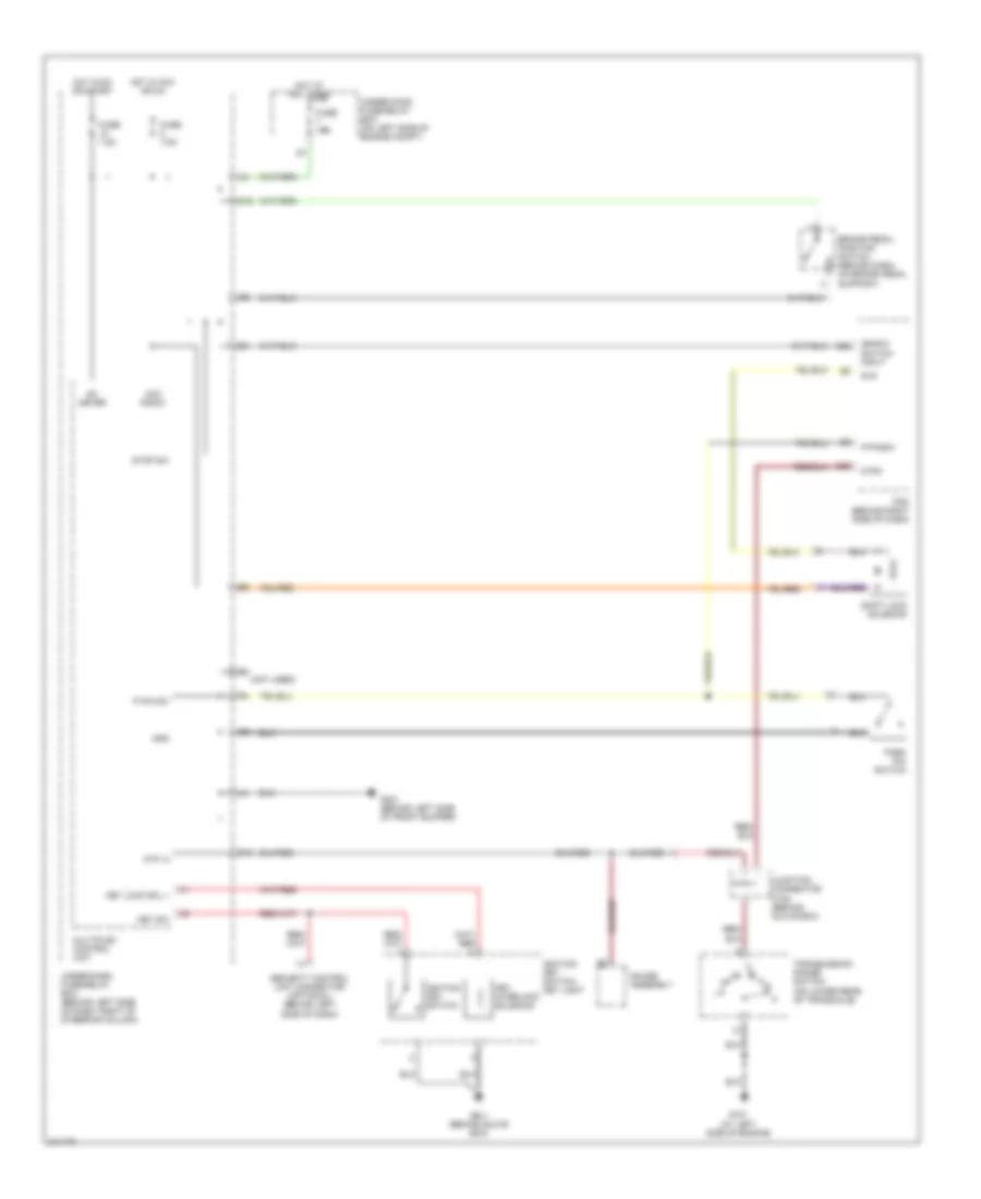
Manual A/C Wiring Diagram (1 of 2) for Honda CR-V SE 2005
 https://portal-diagnostov.com/license.html
Automotive Electricians Portal FZCO
Automotive Electricians Portal FZCO
https://portal-diagnostov.com/license.html
https://portal-diagnostov.com/license.html
Automotive Electricians Portal FZCO
Automotive Electricians Portal FZCO
List of elements for Manual A/C Wiring Diagram (1 of 2) for Honda CR-V SE 2005:
- (behind left side of dash, right of steering column)
- (ecu) bus
- (under left side of dash) g501
- A/c compressor
- A/c compressor clutch
- A/c compressor clutch relay
- A/c press sw
- A/c pressure switch (on right front of engine compartment)
- A23
- Air mix control motor (below left side of dash, on hvac unit)
- Air mix cool
- Air mix hot
- Air mix potential
- Air mix potential +5v
- Amd- p
- Blower feedback
- Blower pwr trans
- Communication
- D10
- Defogger system
- E10
- E12
- E13
- E18
- Ecm/pcm (behind right side of dash)
- Ect sensor (on rear of engine head)
- Engine controls system
- Evap sensor
- Evaporator temperature sensor (behind left side of dash)
- Fan control
- Fresh
- Frs
- Fuse 10a
- Fuse 20a
- Ground
- Heater control unit- panel
- High
- Hot at all times
- Hot in on
- Ig2
- Ignition
- Illumination
- Interior lights system
- Key pushed in
- Low
- M- cool
- M- def
- M- hot
- M- vent
- Mode
- Mode 1
- Mode 2
- Mode 3
- Mode 4
- Mode control motor (behind right side of dash, on hvac unit)
- Mode def
- Multiplex control unit
- Nca
- Rear defog
- Rec
- Recirculate
- Recirculation control motor (behind right side of dash, on blower unit)
- Red
- Relay ctrl
- S- com
- S5v
- Sens gnd
- Sens input
- Sensor ground
- Thermal protector
- To blower motor relay (diagram 2 of 2)
- Under-dash fuse/relay box
- Under-hood fuse/relay box (on left side of engine compt)
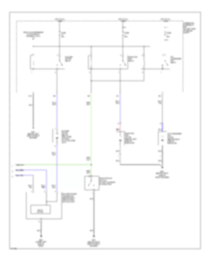
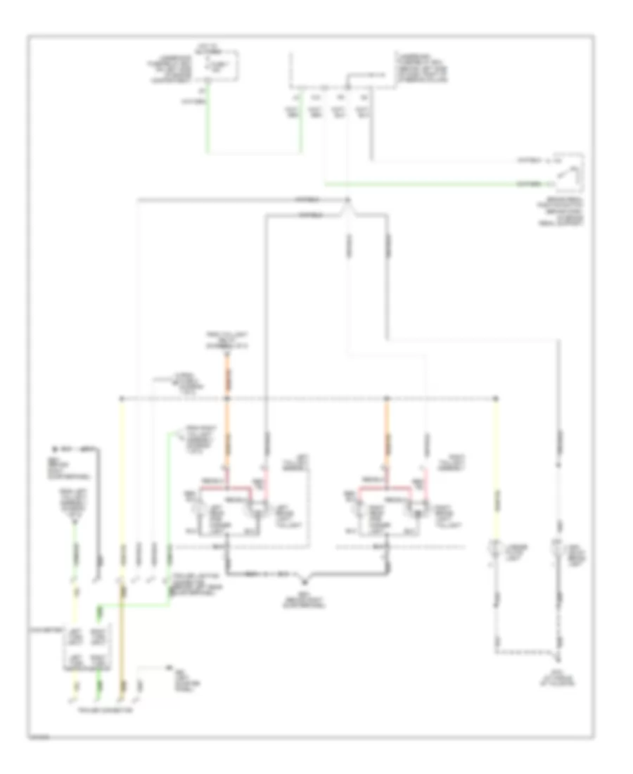
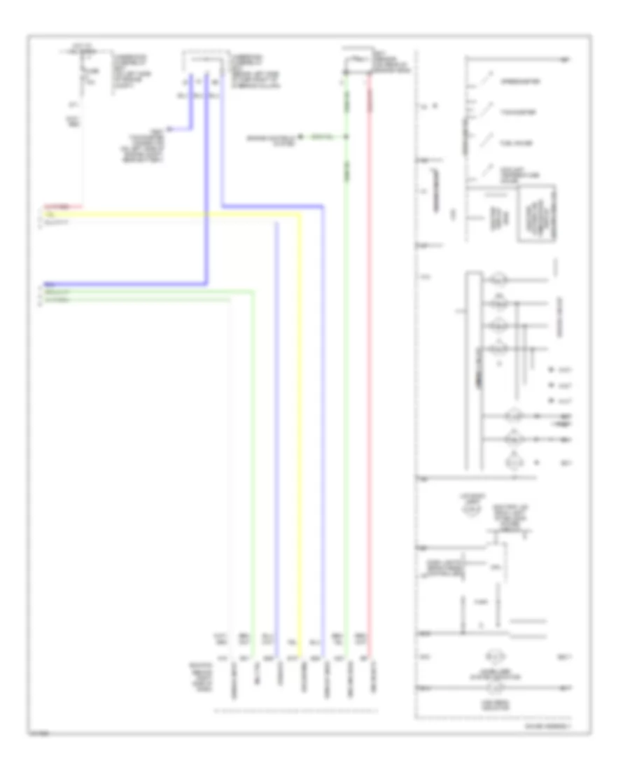
Manual A/C Wiring Diagram (2 of 2) for Honda CR-V SE 2005
List of elements for Manual A/C Wiring Diagram (2 of 2) for Honda CR-V SE 2005:
- A/c condenser fan motor (behind right side of radiator)
- A/c condenser fan relay
- Blower motor (below right side of dash, on a/c blower unit)
- Blower motor relay
- Blower power transistor (behind right side of dash, on hvac unit)
- D13
- From a/c compressor clutch relay (diagram 1 of 2)
- Fuse 20a
- Fuse 40a
- G201 (behind right side of front bumper)
- G301 (behind left side of front bumper)
- G501 (under left side of dash)
- Hot at all times
- Radiator fan motor (behind left side of radiator)
- Radiator fan relay
- Radiator fan switch (at bottom rear of radiator)
- Red
- Solid state
- Underhood fuse/relay box (on left side of engine compt)
ANTI-LOCK BRAKES
Anti-lock Brakes Wiring Diagram for Honda CR-V SE 2005
List of elements for Anti-lock Brakes Wiring Diagram for Honda CR-V SE 2005:
- +b-p
- +b-v
- Abs
- Abs ind
- Abs indicator circuit
- Act
- Blfs
- Brake fluid level switch (on brake fluid reservoir)
- Brake pedal position switch (behind dash, on brake pedal support)
- Can1-h
- Can1-l
- Can2-h
- Can2-l
- Can22
- Can24
- Canada
- Canh
- Canl
- Clst-gnd
- Clst-ig
- Computer data lines system
- Cpu
- Cruise control main
- Drl control unit
- E11
- E22
- E24
- Ecm/pcm (behind right side of dash)
- Fl +b
- Fl-gnd
- Fr +b
- Fr-gnd
- Fuse 10 30a
- Fuse 10 7.5a
- Fuse 18 30a
- Fuse 4 10a
- Fuse 7 15a
- G202 (behind right side of front bumper)
- G301 (behind left side of front bumper)
- G451
- G501 (under left side of dash)
- G502 (under right side of dash)
- Gauge assembly
- Gnd-p
- Gnd-v
- Hot at all times
- Hot in on or start
- Ig1
- Immobilizer control unit receiver (on steering column)
- K-line
- Left front wheel speed sensor (left side of engine compt)
- Left rear wheel speed sensor (under left rear of vehicle)
- Multiplex control unit
- Nca
- O12
- Parking brake switch (under left side of dash)
- Passenger's seat)
- Pnk
- Red
- Right front wheel speed sensor (right side of engine compt)
- Right rear wheel speed sensor (under right rear of vehicle)
- Rl +b
- Rl-gnd
- Rr +b
- Rr-gnd
- Sld-gnd
- Steering angle sensor (in steering column)
- Stop sw
- Str-vcc
- Stra
- Strb
- Strg
- Strga
- Strgb
- Strgg
- Strgz
- Strz
- Switch/ vsa off switch
- Under-dash fuse/ relay box (behind left side of dash, right of steering column)
- Under-dash fuse/relay box (behind left side of dash, right of steering column)
- Under-hood fuse/relay box (on left side of engine compt)
- Usa
- Vcc
- Vsa
- Vsa activation ind
- Vsa diode (under middle of dash)
- Vsa ind
- Vsa indicator circuit
- Vsa modulator control unit (on right side of engine compt)
- Vsa off sw
- Wl-ebd
- Y1 ebd brake lvl sw gnd
- Yaw rate-lateral acceleration sensor (under front
ANTI-THEFT
Anti-theft Wiring Diagram for Honda CR-V SE 2005
List of elements for Anti-theft Wiring Diagram for Honda CR-V SE 2005:
- (behind glove box) g401
- (behind left side of dash, right of steering column) (not used) underdash fuse/relay box connector u1
- Combination light switch
- Driver's door switch (on left "b" pillar)
- Drl h/l sw
- Fr door sw (dr)
- Front passenger's door switch switch (right "b" pillar)
- Fuse 40a
- Fuse 7.5a
- G/h act
- G/h sw
- G50
- G501 (under left side of dash)
- G601 (behind right quarterpanel)
- G701 (at middle of tailgate)
- Hatch glass latch switch 1 (on middle of tailgate)
- Hatch glass opener actuator (on middle of tailgate)
- Horn sw
- Horns system
- Hot at all times
- Hot in on or start
- Ig2
- Ignition key switch
- Ignition key switch/key light
- Interior lights system
- K/l set
- K/l unset
- Key sw
- Left rear door switch (left "c" pillar)
- Microphone
- Multiplex control unit
- Nca
- Other door sw
- P18
- Rear ceiling light diode (under right side of dash)
- Rear wiper control unit (behind right rear quarter panel)
- Red
- Right rear door switch (right "c" pillar)
- Security control unit
- Security hood switch
- Security in-line fuse (under left side of dash)
- Security led
- Tailgate switch
- Trunk sw (t/g sw)
- Underdash fuse/relay box (behind left side of dash, right of steering column)
- Underhood fuse/relay box (on left side of engine compartment)
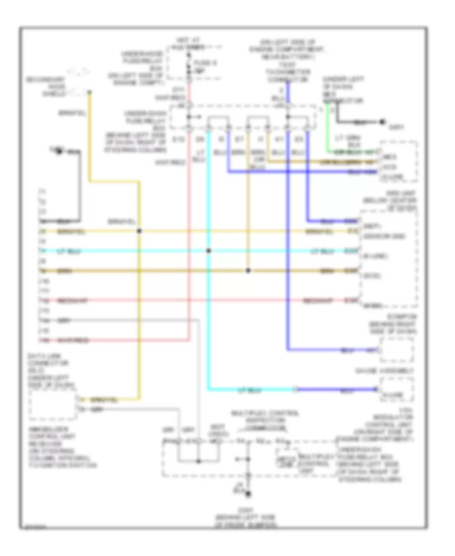
Immobilizer Wiring Diagram for Honda CR-V SE 2005
List of elements for Immobilizer Wiring Diagram for Honda CR-V SE 2005:
- A19
- Auxilliary underhood fuse/relay box
- B10
- B22
- Computer data lines system
- D11
- D12
- E17
- E27
- Ecm/pcm (behind right side of dash)
- Engine controls system
- Fuel pump
- Fuel tank unit (in top of fuel tank)
- Fuse 10a
- Fuse 15a
- Fuse 30a
- G101 (at left side of engine)
- G551 (under driver's seat)
- Gauge assembly
- Ground
- Hot at all times
- Hot in on or start
- Ig1
- Igp1
- Igp2
- Immobi- lizer cord
- Immobilizer control unit receiver (on steering column, integral to ignition switch)
- Immobilizer system indicator
- Imo fpr
- Imocd
- K14
- Lg3
- Mrly
- Multiplex control unit
- Parking brake switch (under left side of dash)
- Pgm-fi main relay 1 (behind right side of dash)
- Pgm-fi main relay 2 (behind right side of dash)
- Underdash fuse/ relay box (behind left side of dash, right of steering column)
- Underdash fuse/relay box (behind left side of dash, right of steering column)
- Underhood fuse/ relay box (on left side of engine compt)
BODY CONTROL MODULES
Body Control Modules Wiring Diagram for Honda CR-V SE 2005
List of elements for Body Control Modules Wiring Diagram for Honda CR-V SE 2005:
- (behind glove box) g401
- (behind left side of front bumper) g301
- (canada)
- (not used)
- (usa)
- +b back up
- +b day lt/fr fog
- +b door lock
- A/c pressure switch
- Acc radio
- Air conditioning system
- Anti-theft system
- Atp-p
- Atpn
- Beeper
- Brake fluid level switch (on brake fluid reservoir)
- Brake switch
- Bus (ecu)
- Bus meter
- C11
- Commu- nication
- D10
- D11
- D14
- Dimmer high
- Door lock actuator
- Door locks system
- Door unlock actuator
- Dr door lck remote in
- Dr door lock input
- Dr door unlk remote in
- Dr door unlock input
- Driver door switch
- Driver seat belt/srs
- Drl h/l sw
- E10
- E13
- Ebd
- Ecm/pcm (behind right side of dash)
- Exterior & interior lights systems
- Exterior lights, cruise control & anti-lock brakes systems
- F11
- Fr washer motor
- Fr wiper (int)
- Fr wiper int unit
- Fr wiper pass
- Fuse 10a
- Fuse 16 20a
- Fuse 20a
- Fuse 3 15a
- Fuse 7.5a
- Fuse 9 10a
- G10
- G502 (under right side of dash)
- Gauge assembly
- Ground
- Hatch glass actuator
- Hatch glass switch
- Headlights high
- Headlights system
- Horn sw
- Horns system
- Hot at all times
- Hot in acc or on
- Hot in on
- Hot in on or start
- Ig 2 day lt
- Ig1 meter
- Ig1 wiper
- Ignition key light
- Ignition key switch
- Ignition key switch/ key light
- Illum +
- Immobilizer
- Instrument cluster & anti-lock brakes systems
- Instrument cluster & sound systems
- Interior lights system
- Interior lights, anti-theft systems
- Interior lights, door locks & anti-theft systems
- Intr lt
- K/l set
- K/l unset
- K10
- K13
- Key lock sol +
- Key lt -
- Key switch input
- Keyless receiver unit
- Lighting rly-
- Mpcs chk
- Multiplex bus
- Multiplex control inspection connector
- Multiplex control unit
- Other door sw
- P pin sw
- P16
- P17
- P18
- Red
- Security control unit connector (optional) (behind left side of dash)
- Shift interlock system
- Signal ground
- Small
- Small lt relay -
- Sound systems
- Stop sw
- Transmissions system
- Trunk sw (t/g sw)
- Trunk, tailgate, fuel doors & anti-theft systems
- Trunk, tailgate, fuel doors, anti-theft & wiper/washer systems
- Underdash fuse/relay box (behind left side of dash, right of steering column)
- Underhood fuse/relay box (on left side of engine compartment)
- Vsa modulator control unit (on right side of engine compt)
- Warning, exterior lights systems
- Wiper/washer system
- Wl-ebd
- Y10
- Y11
- Y12
- Y13
COMPUTER DATA LINES
Computer Data Lines Wiring Diagram for Honda CR-V SE 2005
List of elements for Computer Data Lines Wiring Diagram for Honda CR-V SE 2005:
- (k-line)
- (nep)
- (not used) i4
- (on left side of engine compartment, near battery) test tachometer connector
- (scs)
- (under left of dash) mes connector
- (wen)
- A24
- D11
- Data link connector (dlc) (under left side of dash)
- E12
- E23
- E25
- E29
- E30
- Ecm/pcm (behind right side of dash)
- Fuse 9 10a
- G301 (behind left side of front bumper)
- G451
- Gauge assembly
- Hot at all times
- Immobilizer control unit receiver (on steering column, integral to ignition switch)
- K-line
- Mes
- Mpcs chk
- Multiplex control inspection connector
- Multiplex control unit
- P14
- Scs
- Secondary ho2s shield
- Sensor gnd
- Srs unit (below center of dash)
- Under-dash fuse/relay box (behind left side of dash, right of steering column)
- Under-hood fuse/relay box (on left side of engine compt)
- Vsa modulator control unit (on right side of engine compartment)
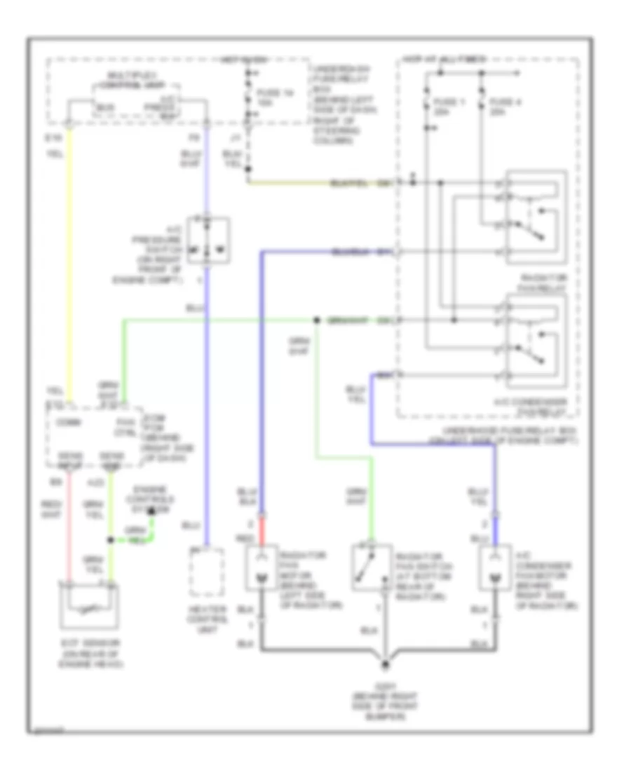
COOLING FAN
Cooling Fan Wiring Diagram for Honda CR-V SE 2005
List of elements for Cooling Fan Wiring Diagram for Honda CR-V SE 2005:
- A/c condenser fan motor (behind right side of radiator)
- A/c condenser fan relay
- A/c press sw
- A/c pressure switch (on right front of engine compt)
- A23
- Bus
- Comm
- E10
- E13
- Ecm/ pcm (behind right side of dash)
- Ect sensor (on rear of engine head)
- Engine controls system
- Fan ctrl
- Fuse 1 20a
- Fuse 14 10a
- Fuse 4 20a
- G201 (behind right side of front bumper)
- Heater control unit
- Hot at all times
- Hot in on
- Multiplex control unit
- Radiator fan motor (behind left side of radiator)
- Radiator fan relay
- Radiator fan switch (at bottom rear of radiator)
- Red
- Sens gnd
- Sens input
- Underdash fuse/relay box (behind left side of dash, right of steering column)
- Underhood fuse/relay box (on left side of engine compt)
CRUISE CONTROL
Cruise Control Wiring Diagram for Honda CR-V SE 2005
List of elements for Cruise Control Wiring Diagram for Honda CR-V SE 2005:
- "on"
- (at left side of engine) g101
- (on left side of engine) g101
- 15a
- A/t
- A12
- A18
- A20
- A21
- A23
- A24
- A25
- A26
- App sensor (right rear of engine compartment)
- Apsa
- Apsb
- Atpfwd
- Auxiliary under-hood fuse/relay box (left side of engine compt)
- B19
- B20
- Bksw
- Bkswnc
- Brake pedal position switch (behind dash, on brake pedal support)
- C10
- C18
- Cable reel
- Cancel switch
- Clutch pedal position switch (m/t) (on clutch pedal support)
- Controls system
- Crmsw
- Crmtcls
- Crressw
- Crsetsw
- Cruise control ind
- Cruise control main switch
- Cruise control main switch/ vsa off switch
- Cruise control set/ resume/ cancel switch
- D15
- D16
- Dbw m+
- Dbw m-
- Dbwrly
- E22
- Ecm/pcm (behind right side of dash)
- Engine
- Ex, usa: se, canada: ex-l
- Fuse 10 7.5a
- Fuse 31
- Fuse 4 10a
- Fuse 7 15a
- Fuse 8 15a
- G101 (at left side of engine)
- G501 (under left side of dash)
- Gauge assembly
- Horn relay
- Horn sw
- Horns system
- Hot at all times
- Hot in on or start
- Indicator
- Interior lights system
- J/c c105 (behind glove box)
- Junction connector c103 (at rear of engine)
- Junction connector c105 (behind glove box)
- Junction connector c105 (behind glove box)
- M/t
- Mrly
- Multiplex control unit
- O12
- Output shaft (counter shaft) speed sensor (a/t) (on front right side of transmission)
- Pg2
- Pgm-fi main relay 1 (behind right side of dash)
- Pnk c3
- Red
- Resume switch
- Sedf
- Sefd
- Set ind
- Set switch
- Sg1
- Sg2
- Steering wheel
- Thl 2
- Thl1
- Throttle actuator control module (behind right side of dash)
- Throttle actuator control module relay
- Tp sensor/ throttle actuator (on right side of throttle body)
- Transmission range switch (a/t) (on lower rear transaxle)
- Under-hood fuse/relay box (on left side of engine compartment)
- Underdash fuse/relay box (behind left end of dash)
- Underdash fuse/relay box (behind left side of dash, right of steering column)
- Vcc
- Vcc1
- Vcc2
- Vss (m/t) (on top of transmission)
- Vss/nc
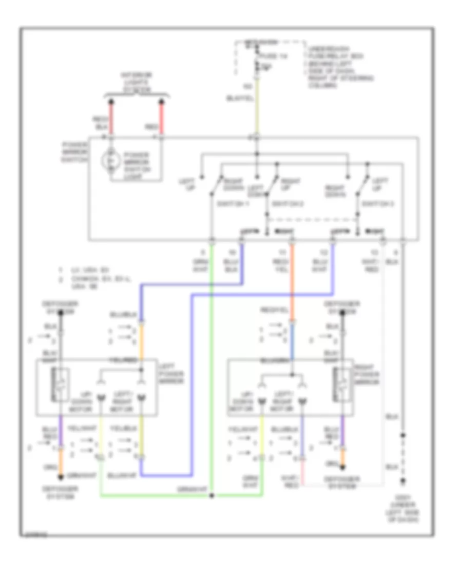
DEFOGGERS
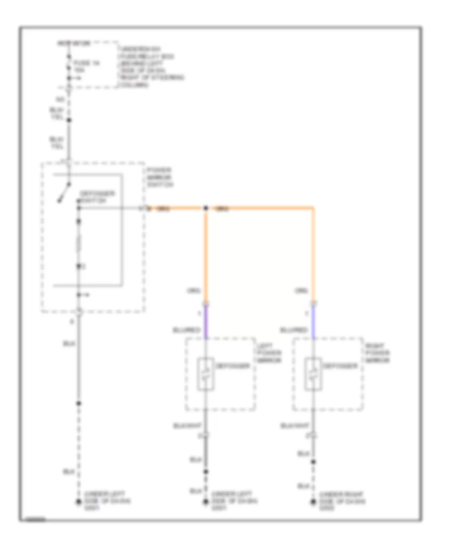
Heated Mirrors Wiring Diagram for Honda CR-V SE 2005
List of elements for Heated Mirrors Wiring Diagram for Honda CR-V SE 2005:
- (under left side of dash) g501
- (under right side of dash) g502
- Defogger
- Defogger switch
- Fuse 14 10a
- Hot in on
- Left power mirror
- Power mirror switch
- Right power mirror
- Underdash fuse/relay box (behind left side of dash, right of steering column)
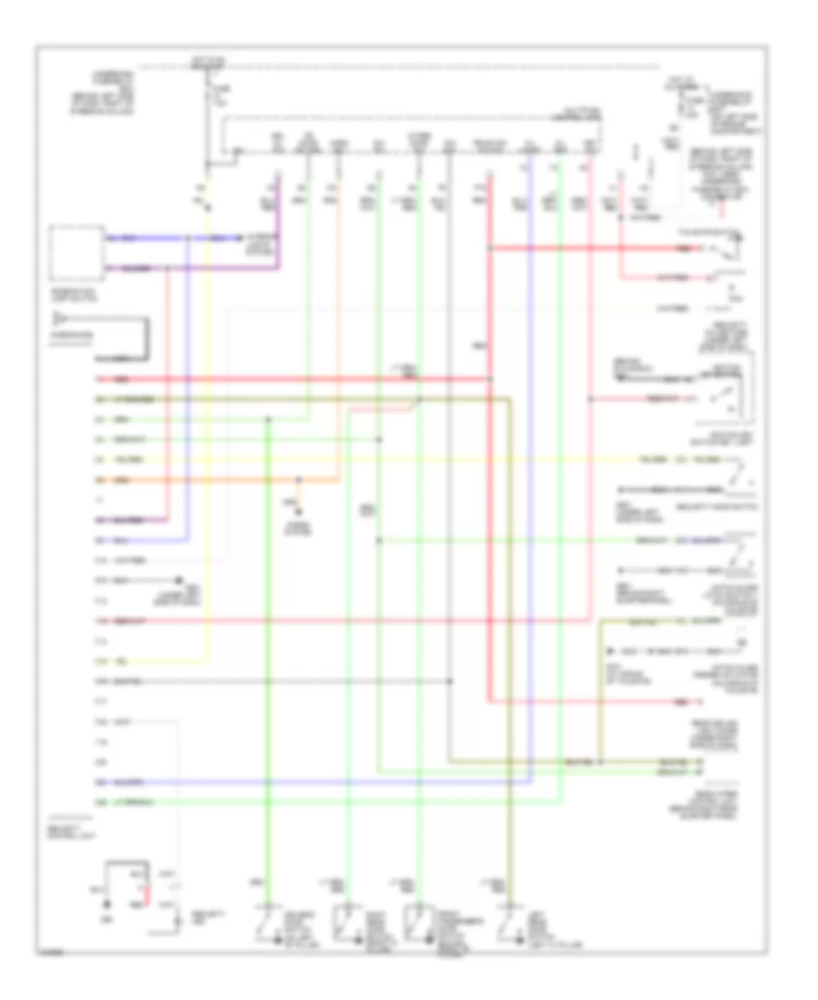
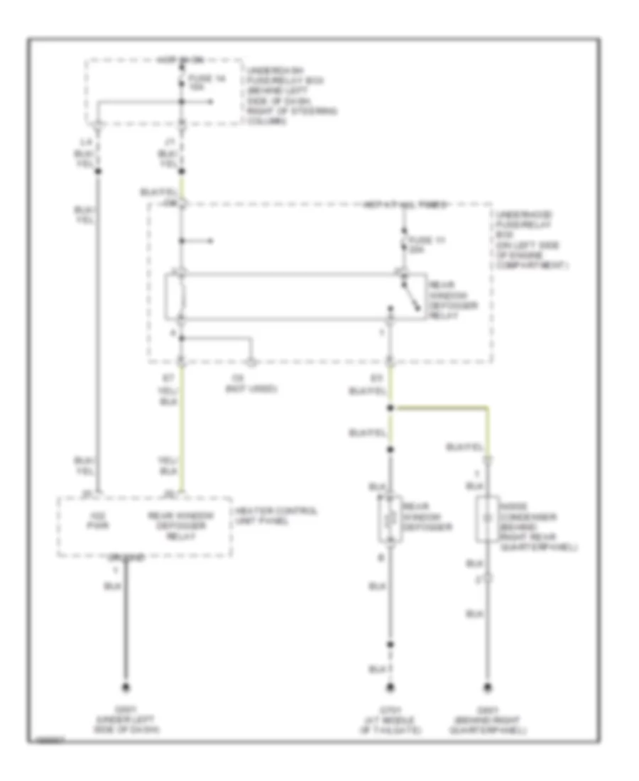
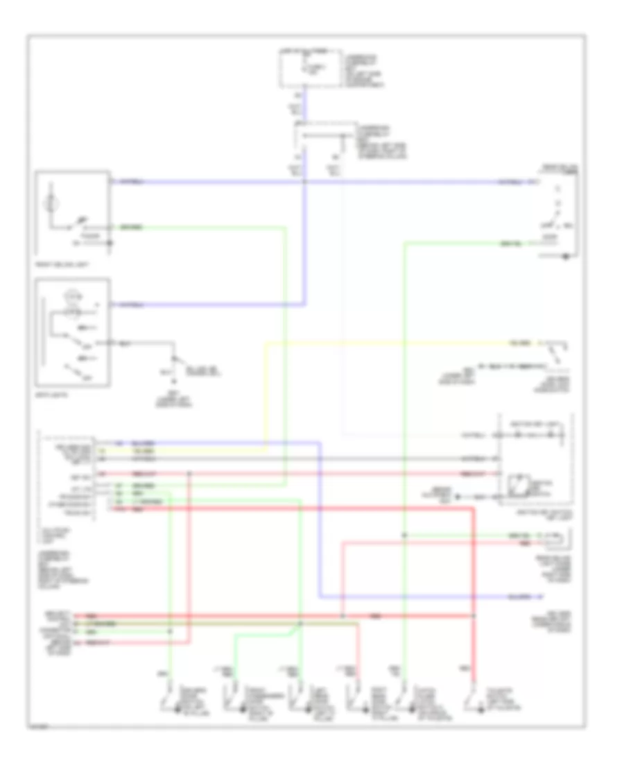
Rear Defogger Wiring Diagram for Honda CR-V SE 2005
List of elements for Rear Defogger Wiring Diagram for Honda CR-V SE 2005:
- (not used)
- Fuse 11 20a
- Fuse 14 10a
- G501 (under left side of dash)
- G601 (behind right quarterpanel)
- G701 (at middle of tailgate)
- Ground
- Heater control unit panel
- Hot at all times
- Hot in on
- Ig2 pwr
- Noise condenser (behind right rear quarterpanel)
- Rear window defogger
- Rear window defogger relay
- Underdash fuse/relay box (behind left side of dash, right of steering column)
- Underhood fuse/relay box (on left side of engine compartment)
ENGINE PERFORMANCE
2.4L
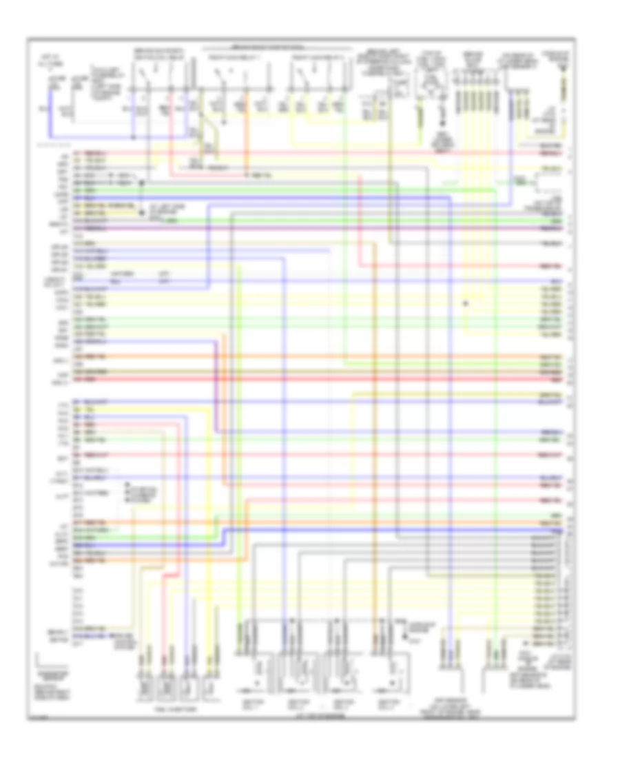
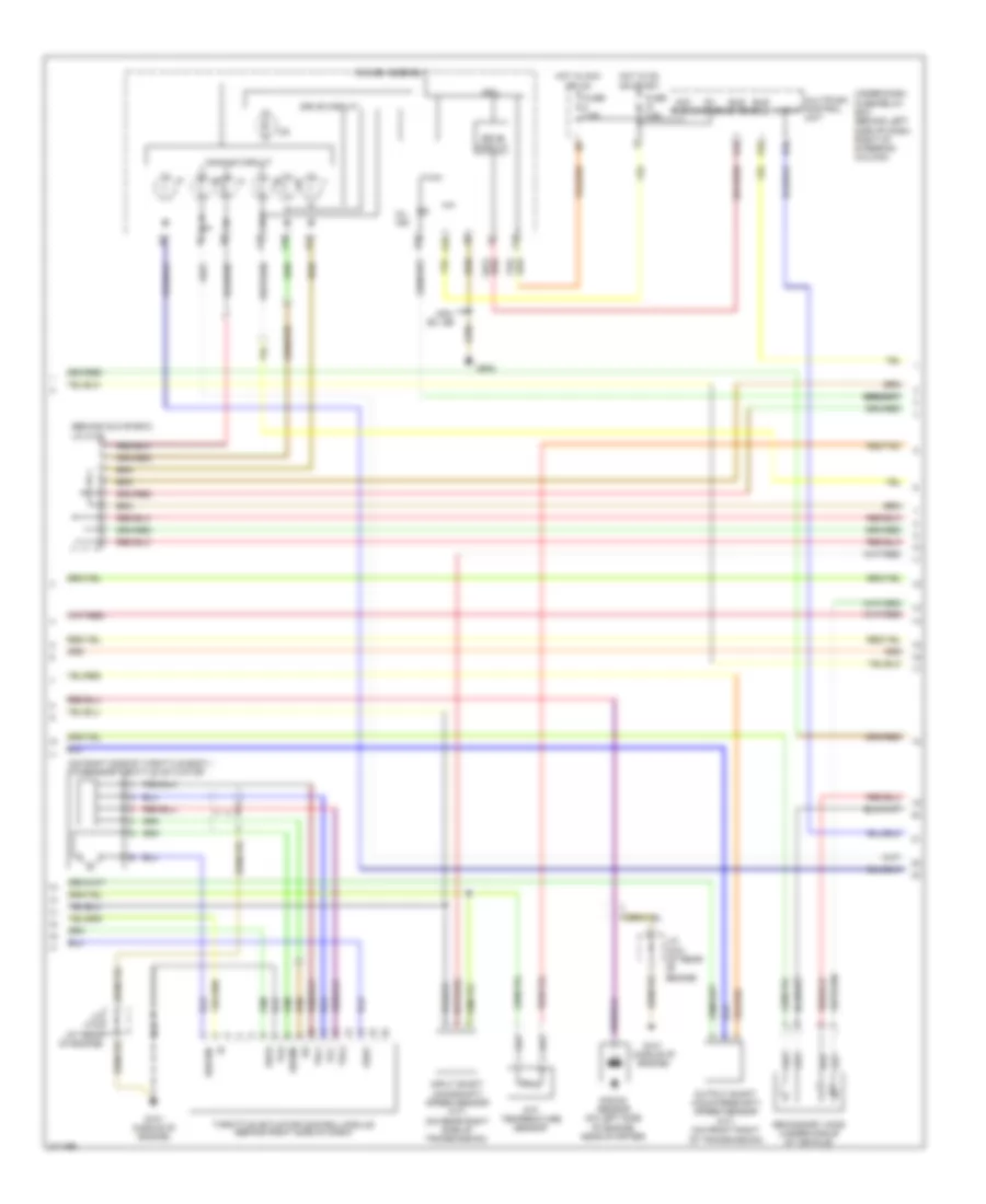
2.4L, Engine Performance Wiring Diagram (1 of 4) for Honda CR-V SE 2005
List of elements for 2.4L, Engine Performance Wiring Diagram (1 of 4) for Honda CR-V SE 2005:
- (a/t)
- (at left side of engine) g101
- (at top of engine)
- (behind glove box)
- (behind glove box) j/c c105
- (behind left side of dash, right of steering column) under-dash fuse/relay box
- (behind right side of dash)
- (m/t)
- (middle of engine)
- (on rear of cylinder head) cmp sensor a
- (top of fuel tank) fuel tank unit
- A10
- A11
- A12
- A13
- A14
- A15
- A16
- A17 a18
- A19
- A20
- A21
- A22
- A23
- A24
- A25
- A26
- A27
- A28
- A29
- A30
- A31
- Afs (+)
- Afs (-)
- Afshtc
- All times
- Altc
- Altf
- Altl
- Apsa
- Apsb
- Auxiliary fuse/relay box (left side of engine compt)
- B10
- B11
- B12
- B13
- B14
- B15
- B16
- B17
- B18
- B19
- B20
- B21
- B22
- B23
- B24
- Barometer sensor
- Ckp
- Ckp sensor (on lower left front of engine, near crankshaft pulley)
- Cmp sensor b (on rear of cylinder head)
- Cmpa
- Cmpb
- Cruise control system
- D10
- D11
- D12
- D13
- D14
- D15
- D16
- D17
- Dbwrly
- Ecm/pcm (behind right side of dash)
- Ect
- Fuel injectors
- Fuel pump
- Fuse 15a
- G101
- G101 (middle of engine)
- G551 (under driver's seat)
- Hot at
- Iat
- Icm
- Ignition coil 1
- Ignition coil 2
- Ignition coil 3
- Ignition coil 4
- Ignition coil relay
- Igp1
- Igp2
- Igpls1
- Igpls2
- Igpls3
- Igpls4
- Imt
- Imtvps
- Inj1
- Inj2
- Inj3
- Inj4
- J/c c103 (at rear of engine)
- Lg1
- Lg2
- Map
- Pcs
- Pg1
- Pg2
- Pgm-f1 main relay 1
- Pgm-f1 main relay 2
- Red
- Sedf
- Sefd
- Setind
- Sg1
- Sg2
- Starting/ charging system
- Vcc1
- Vcc2
- Vss(m/t) nc (a/t)
- Vtc
- Vtpsw
- Vts
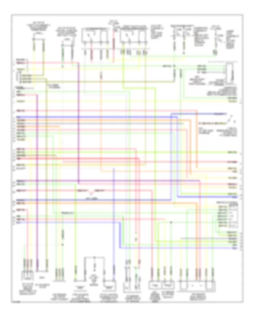
2.4L, Engine Performance Wiring Diagram (2 of 4) for Honda CR-V SE 2005
List of elements for 2.4L, Engine Performance Wiring Diagram (2 of 4) for Honda CR-V SE 2005:
- (at rear of engine)
- (behind glove box) j/c c105
- (not used)
- (on top of evap control canister) evap canister vent shut valve
- (on top of throttle assembly) evap canister purge valve
- A/f sensor (under middle of vehicle)
- A/f sensor relay
- Air duct)
- App sensor (right rear of engine compt)
- Auxiliary fuse/relay box (left side of engine compt)
- C10
- Ect sensor (on rear of engine head)
- Eld unit
- Fuse 10a
- Fuse 20a
- Fuse 7.5a
- G101 (at left side of engine)
- G201 (behind right side of front bumper)
- Hot at all times
- Hot in on or start
- Iat sensor (on intake
- Imt solenoid valve
- Imt valve position sensor (right front of engine compt)
- Map sensor (on top of throttle body)
- Power distribution system
- Red
- Throttle actuator control module relay
- Under- hood fuse/relay box (on left side of engine compt)
- Under-dash fuse/relay box (behind left side of dash, right of steering column)
- Vtc oil control solenoid valve (on front of cylinder head)
- Vtec oil pressure switch (on front of cylinder head)
- Vtec solenoid valve (on right front of cylinder head)
2.4L, Engine Performance Wiring Diagram (3 of 4) for Honda CR-V SE 2005
List of elements for 2.4L, Engine Performance Wiring Diagram (3 of 4) for Honda CR-V SE 2005:
- (behind glove box)
- (on right side of throttle body.) tp/sensor/throttle actuator
- A13
- A14
- A15
- A16
- A18
- Acc radio
- Atf temperature sensor
- Atp-p
- B20
- Bus (ecu)
- Bus meter
- Cpu
- Dbw m+
- Dbwm-
- Dimming circuit
- Drive circuit
- E10
- Fuse 7.5a
- G101 (middle of engine)
- G502
- Gauge assembly
- Hot in acc or on
- Hot in on or start
- Ig1 meter
- Input shaft (mainshaft) speed sensor (a/t) (on rear right side of transmission)
- J/c c103 (at rear of engine)
- J/c c105
- K10
- Knock sensor (on left side of engine, near starter)
- Mil ind
- Multiplex control unit
- Output shaft (countershaft) speed sensor (a/t) (on front right of transmission)
- Pg2
- Secondary ho2s (under middle of vehicle)
- Sedf
- Sefd
- Thl1
- Thl2
- Throttle actuator control module (behind right side of dash)
- Under-dash fuse/relay box (behind left side of dash, right of steering column)
- Usa: ex, se
- Vcc
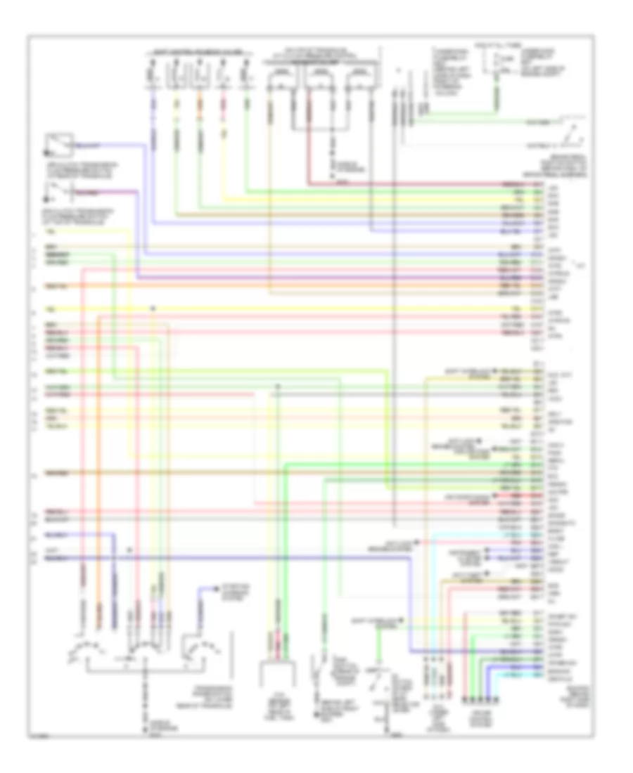
2.4L, Engine Performance Wiring Diagram (4 of 4) for Honda CR-V SE 2005
List of elements for 2.4L, Engine Performance Wiring Diagram (4 of 4) for Honda CR-V SE 2005:
- anti-lock brakes system
- (a/t)
- (behind left side of front bumper) g301
- (middle of engine)
- (middle of engine) g101
- (on top of transaxle) a/t clutch pressure control solenoid valves
- 2nd clutch transmission fluid pressure switch (at top of transaxle)
- 3rd clutch transmission fluid pressure switch (at rear of transaxle)
- A/t
- Acc
- Afshtcr
- Air conditioning system
- Anti-lock brakes system
- Anti-theft system
- Atft
- Atp1
- Atp2
- Atpd
- Atpfwd
- Atpn
- Atpp
- Atpr
- Atprvs
- Bksw
- Bkswnc
- Brake pedal position switch (behind dash, on brake pedal support)
- C10
- C11
- C12
- C13
- C14
- C15
- C16
- C17
- C18
- C19
- C20
- C21
- C22
- Can h
- Can l
- Cooling fans system
- Cr res sw
- Cr set sw
- Crmsw
- Crmtcls
- Cruise control system
- D3 switch (on end of a/t gear selector lever)
- D3sw
- Dlc (under left side of dash)
- E10
- E11
- E12
- E13
- E14
- E15
- E16
- E17
- E18
- E19
- E20
- E21
- E22
- E23
- E24
- E25
- E26
- E27
- E28
- E29
- E30
- E31
- Ecm/pcm (behind right side of dash)
- Eld
- Fanc
- Ftp
- Ftp sensor (on left rear of fuel tank)
- Fuse 15a
- G101
- G451
- Hot at all times
- Ig1
- Imo fpr
- Imocd
- Instrument cluster system
- K-line
- Lg3
- Lsa
- Lsb
- Lsc
- Mil
- Mrly
- Nep
- O12
- Op2sw
- Op3sw
- P-pin sw
- Pnk
- Psp switch (rear of engine compt)
- Pspsw
- Red
- Scs
- Sefmj
- Sg3
- Sha
- Shb
- Shc
- Shd
- She
- Shift control solenoid valves
- Shift interlock system
- Sho2s
- Sho2shtc
- Sls
- Starting/ charging system
- Transmission range switch (on lower rear of transaxle)
- Under-dash fuse/relay box (behind left side of dash, right of steering column)
- Under-hood fuse/relay box (on left side of engine compt)
- Vcc3
- Vssout
- Vsv
- Wen
EXTERIOR LIGHTS
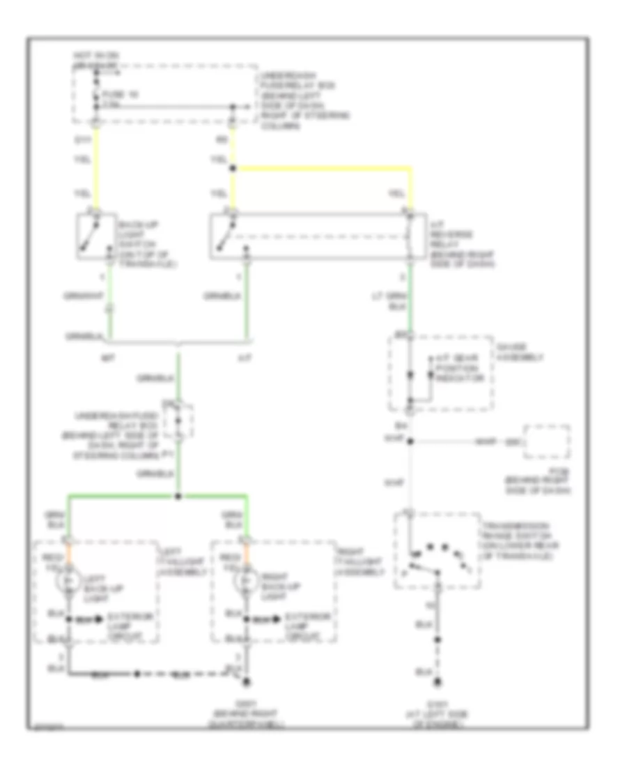
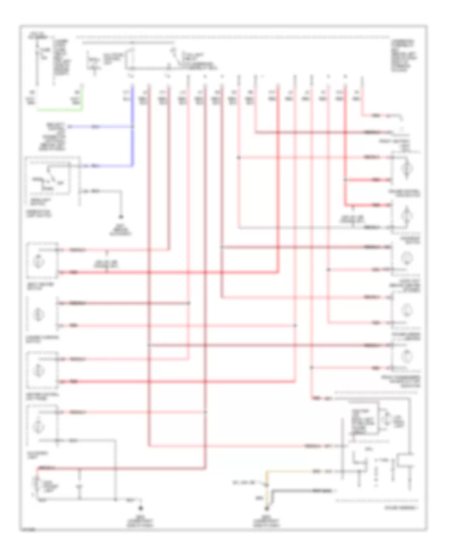
Back-up Lamps Wiring Diagram for Honda CR-V SE 2005
List of elements for Back-up Lamps Wiring Diagram for Honda CR-V SE 2005:
- A/t
- A/t gear position indicator
- A/t reverse relay (behind right side of dash)
- Back-up light switch (on top of transaxle)
- D11
- Exterior lamp circuit
- Fuse 10 7.5a
- G101 (at left side of engine)
- G601 (behind right quarterpanel)
- Gauge assembly
- Hot in on or start
- Left back-up light
- Left taillight assembly
- M/t
- Pcm (behind right side of dash)
- Right back-up light
- Right taillight assembly
- Transmission range switch (on lower rear of transaxle)
- Underdash fuse/ relay box (behind left side of dash, right of steering column)
- Underdash fuse/relay box (behind left side of dash, right of steering column)
Exterior Lamps Wiring Diagram (1 of 2) for Honda CR-V SE 2005
List of elements for Exterior Lamps Wiring Diagram (1 of 2) for Honda CR-V SE 2005:
- (behind left side of dash) security control unit connector
- (not used)
- B11
- B12
- B15
- Back-up lamps circuit
- C11
- C12
- C13
- Combination light switch
- Compartment)
- Fuse 19 7.5a
- Fuse 5 15a
- Fuse 6 15a
- G201 (behind right side of front bumper)
- G301 (behind left side of front bumper)
- G401 (behind glove box)
- G502 (under right side of dash)
- G601 (behind right quarterpanel)
- Gauge assembly
- Hazard warning switch
- Hazard warning switch light
- Head
- Headlight switch
- Hot at all times
- Hot in on or start
- Interior lights system
- Left
- Left front parking light
- Left front turn signal/ side marker light
- Left rear turn signal light
- Left taillight assembly
- Left turn signal indicator
- M12
- Multiplex control unit
- Off
- P15
- Park
- Red
- Right
- Right front parking light
- Right front turn signal/ side marker light
- Right rear turn signal light
- Right taillight assembly
- Right turn signal indicator
- Taillight relay
- To brake light/ taillights (diagram 2 0f 2)
- To trailer lighting connector (diagram 2 of 2)
- Turn signal switch
- Turn signal/ hazard relay
- Underdash fuse/relay box (behind left side of dash, right of steering column)
- Underhood fuse/relay box (on left side of engine
Exterior Lamps Wiring Diagram (2 of 2) for Honda CR-V SE 2005
List of elements for Exterior Lamps Wiring Diagram (2 of 2) for Honda CR-V SE 2005:
- (behind dash, on brake pedal support)
- (behind left side of dash, right of steering column)
- Brake pedal position switch
- Converter
- From fuse 5 (diagram 1 of 2)
- From left taillight assembly (diagram 1 of 2)
- From right taillight assembly (diagram 1 of 2)
- From taillight relay (diagram 1 of 2)
- Fuse 7 15a
- G60 (left quarter panel)
- G601 (behind right quarterpanel)
- G701 (at middle of tailgate)
- High mount brake light
- Hot at all times
- Left brake light/ taillight
- Left rear side marker light
- Left taillight assembly
- Left turn input
- Left turn output
- License plate light
- Right brake light/ taillight
- Right rear side marker light
- Right taillight assembly
- Right turn input
- Right turn output
- Trailer connector
- Trailer lighting connector (behind left rear quarterpanel)
- Underdash fuse/relay box
- Underhood fuse/relay box (on left side of engine compartment)
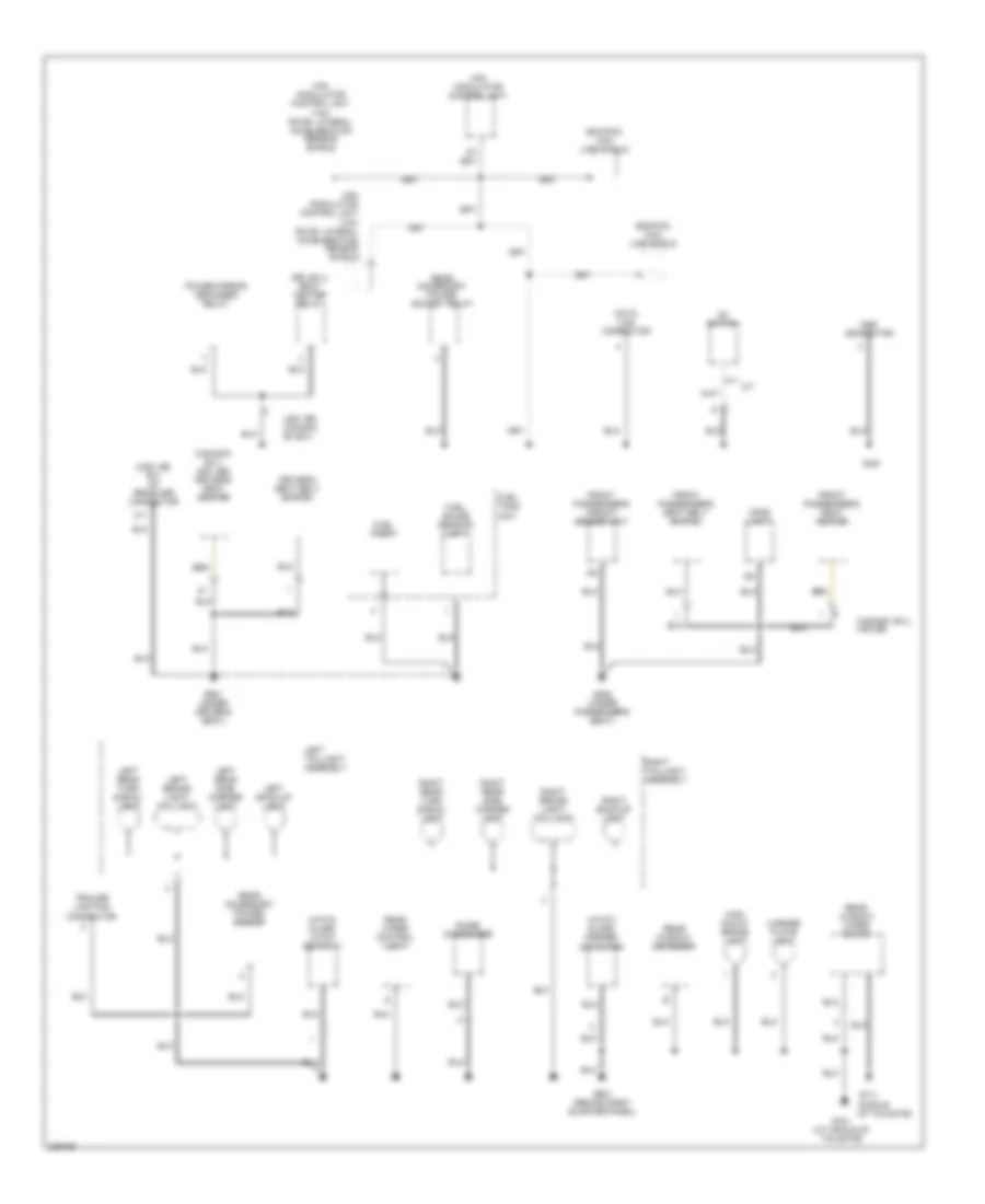
GROUND DISTRIBUTION
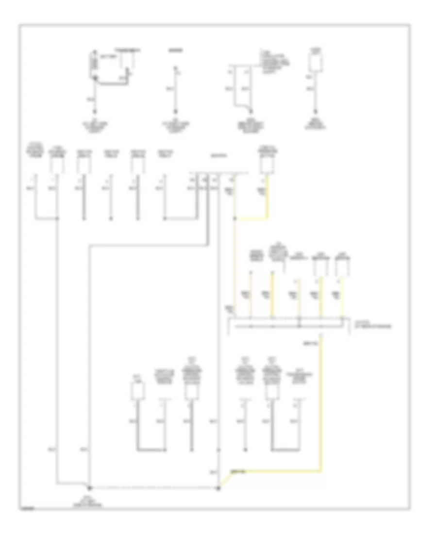
Ground Distribution Wiring Diagram (1 of 4) for Honda CR-V SE 2005
List of elements for Ground Distribution Wiring Diagram (1 of 4) for Honda CR-V SE 2005:
- (a/t) a/t clutch pressure control solenoid valve a
- (a/t) a/t clutch pressure control solenoid valve b
- (a/t) a/t clutch pressure control solenoid valve c
- (a/t) transmission range switch
- (at rear of engine)
- (m/t)
- A20
- Audio unit
- Battery
- Ckp sensor
- Cmp sensor a
- Cmp sensor b
- Ecm/pcm
- Engine
- G1 (at left side of engine compt)
- G101 (at left side of engine)
- G2 (at right side of engine compt)
- G202 (behind right side of front bumper)
- G503 (behind glove box)
- Ignition coil 1
- Ignition coil 2
- Ignition coil 3
- Ignition coil 4
- J/c c103
- Knock sensor shield
- Throttle actuator control module
- Throttle actuator shield
- Tp sensor/
- Transmission
- Vsa modulator control unit (on right side of engine compt)
- Vss
- Vtc oil control solenoid valve
- Vtec oil pressure switch
- Vtec solenoid valve
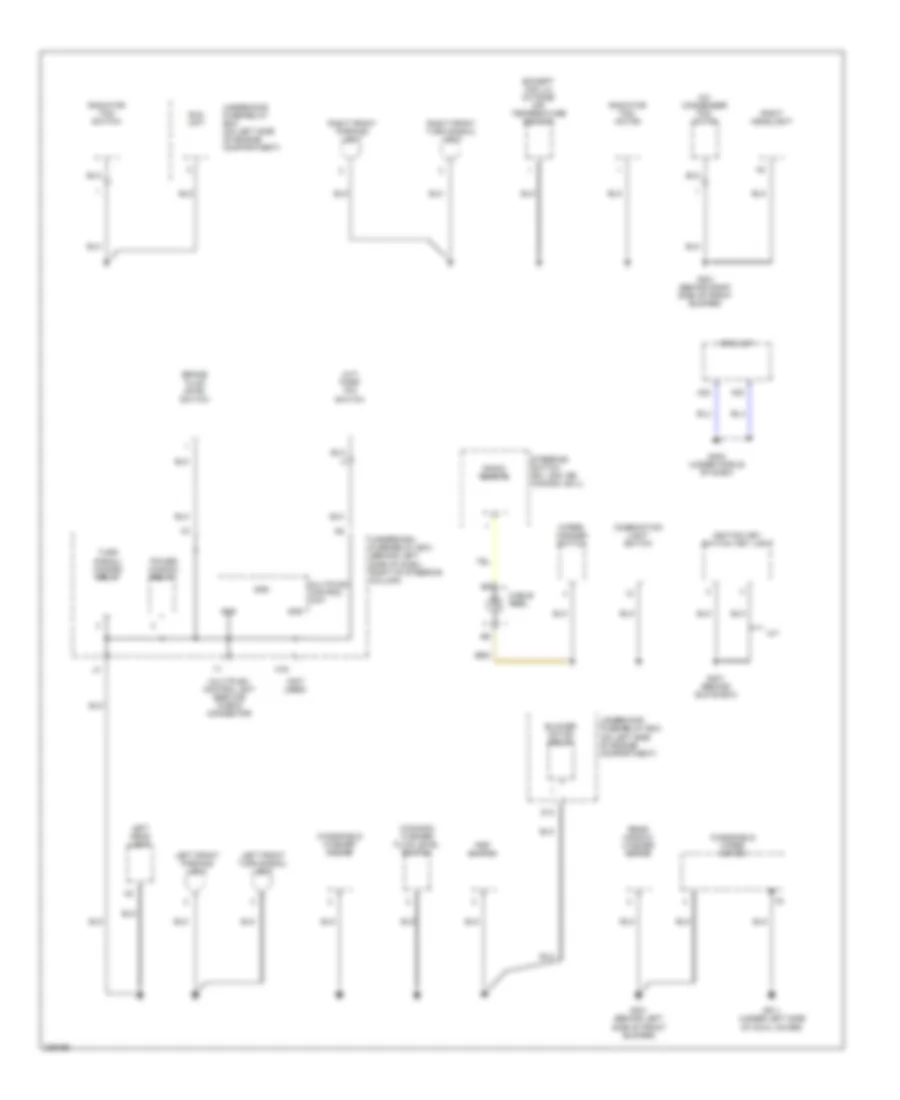
Ground Distribution Wiring Diagram (2 of 4) for Honda CR-V SE 2005
List of elements for Ground Distribution Wiring Diagram (2 of 4) for Honda CR-V SE 2005:
- (a/t) park pin switch
- (canada) washer fluid level switch
- (except usa lx) outside air temperature sensor
- (not used)
- A/c condenser fan motor
- A/t
- A22
- A23
- Blower motor relay
- Brake fluid level switch
- Cable reel
- Combination light switch
- D13
- Eld unit
- G201 (behind right side of front bumper)
- G301 (behind left side of front bumper)
- G401 (behind glove box)
- G402 (under middle of dash)
- G811 (under left side of cowl cover)
- Gnd
- Ignition key switch/ key light
- K16
- Left front parking light
- Left front turn signal/ light
- Left head light
- Multiplex control unit
- Multiplex control unit service check connector
- Power window relay
- Psp switch
- Radiator fan motor
- Radiator fan switch
- Radio remote
- Rear window washer motor
- Right front parking light
- Right front turn signal/ light
- Right headlight
- Srs unit
- Steering switch (ex, usa: se, canada: ex-l)
- Turn signal/ hazard relay
- Underdash fuse/relay box (behind left side of dash, right of steering column)
- Underhood fuse/relay box (on left side of engine compartment)
- Windshield washer motor
- Windshield wiper motor
- Wiper/ washer switch
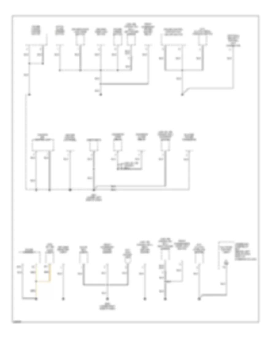
Ground Distribution Wiring Diagram (3 of 4) for Honda CR-V SE 2005
List of elements for Ground Distribution Wiring Diagram (3 of 4) for Honda CR-V SE 2005:
- (canada) drl control unit
- (m/t) clutch interlock switch
- (m/t) clutch pedal position switch
- (m/t) coin pocket light
- (optional) security control unit connector
- (usa: ex, se)
- (usa: ex, se, canada: ex-l)
- (usa: ex, se, canada: ex-l) moonroof switch
- (usa: se canada: ex, ex-l) right power mirror
- (usa: se, canada: ex, ex-l) left power mirror
- (usa: se, canada: ex-l) seat heater switch
- Audio unit
- B11
- B15
- Blower power transistor
- Cruise control main switch/ vsa off switch
- Driver's door lock knob switch
- Driver's door lock switch
- Front accessory power socket
- Front accessory power socket relay
- Front passenger's door lock switch
- G501 (under left side of dash)
- G502 (under right side of dash)
- Gauge assembly
- Glove box light
- Hatch glass opener switch
- Heater control unit-panel
- Keyless receiver unit
- Moonroof close relay
- Moonroof open relay
- Multiplex control unit
- Power mirror switch
- Power window master switch
- S- gnd
- Spotlights
- Underdash fuse/relay box (behind left side of dash, right of steering column)
Ground Distribution Wiring Diagram (4 of 4) for Honda CR-V SE 2005
List of elements for Ground Distribution Wiring Diagram (4 of 4) for Honda CR-V SE 2005:
- (canada: ex-l usa: se) driver's seat heater
- (middle of tailgate)
- (se, ex-l) seat heater relay
- (usa: se, ex) xm receiver connector
- A/t
- A11
- Canada: ex-l usa:se
- D3 switch
- Data link connector
- Driver's seat belt switch
- Ecm/pcm can line shield
- Front passenger's seat belt switch
- Front passenger's seat heater
- Front passenger's weight sensor unit
- Fuel gauge sending unit
- Fuel pump
- Fuel tank unit
- G451
- G551 (under driver's seat)
- G552 (under passenger's seat)
- G601 (behind right quarter panel)
- G701 (at middle of tailgate)
- G711
- Hatch glass latch switch 1
- Hatch glass opener actuator
- High mount brake light
- Left back-up light
- Left brake light/ taillight
- Left rear side marker light
- Left rear turn signal light
- Left taillight assembly
- License plate light
- Mes connector
- Noise condenser
- Opds unit
- Power mirror defogger relay
- Rear accessory power socket
- Rear accessory power socket relay
- Rear window defogger
- Rear window wiper motor
- Rear wiper control unit
- Right back-up light
- Right brake light/ taillight
- Right rear side marker light
- Right rear turn signal light
- Right taillight assembly
- Trailer lighting connector
- Usa: se, canada: ex,ex-l
- Vsa modulator control unit
- Yaw rate- lateral acceleration sensor shield
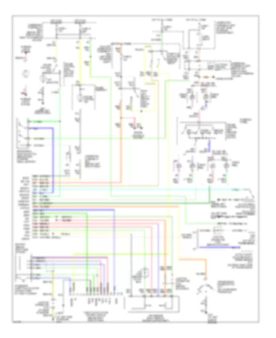
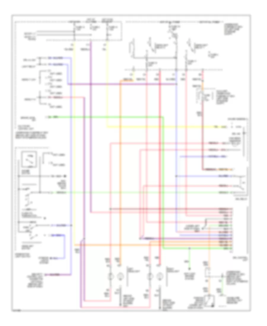
HEADLIGHTS
Headlights Wiring Diagram, with DRL for Honda CR-V SE 2005
List of elements for Headlights Wiring Diagram, with DRL for Honda CR-V SE 2005:
- (behind left side of front bumper) g301
- (behind right side of front bumper) g201
- (not used)
- (under left side of dash) g501
- +b day lt/ fr fog
- A18
- A21
- Anti-lock brakes
- Auxiliary under-hood fuse/relay box (left side of engine compt)
- B14
- Brake level sw
- Combination light switch
- Control unit connector (optional) (behind left side of dash)
- Dimmer switch
- Drl control unit
- Drl h/l sw
- Drl ind
- Drl relay
- Eld unit
- F10
- F11
- F12
- Flash-to- pass switch
- Fuse 10 7.5a
- Fuse 12 7.5a
- Fuse 15 20a
- Fuse 17 20a
- Fuse 19 100a
- Fuse 2 30a
- Fuse 3 10a
- Fuse 7.5a
- G401 (behind glove box)
- Gauge assembly
- Head
- Headlight relay 1
- Headlight relay 2
- Headlight switch
- Headlt hi
- Headlt low
- High
- High beam indicator
- Hot at all times
- Hot in on
- Hot in on or start
- Ig2 day lt
- Immobilizer control unit receiver
- Interior lights system
- Left headlight
- Light relay
- Low
- Multiplex control unit
- Off
- Park
- Parking brake switch (under left side of dash)
- Red
- Right headlight
- Security
- System
- Under-dash fuse/relay box (behind left side of dash, right of steering column)
- Under-hood fuse/relay box (on left side of engine compt)
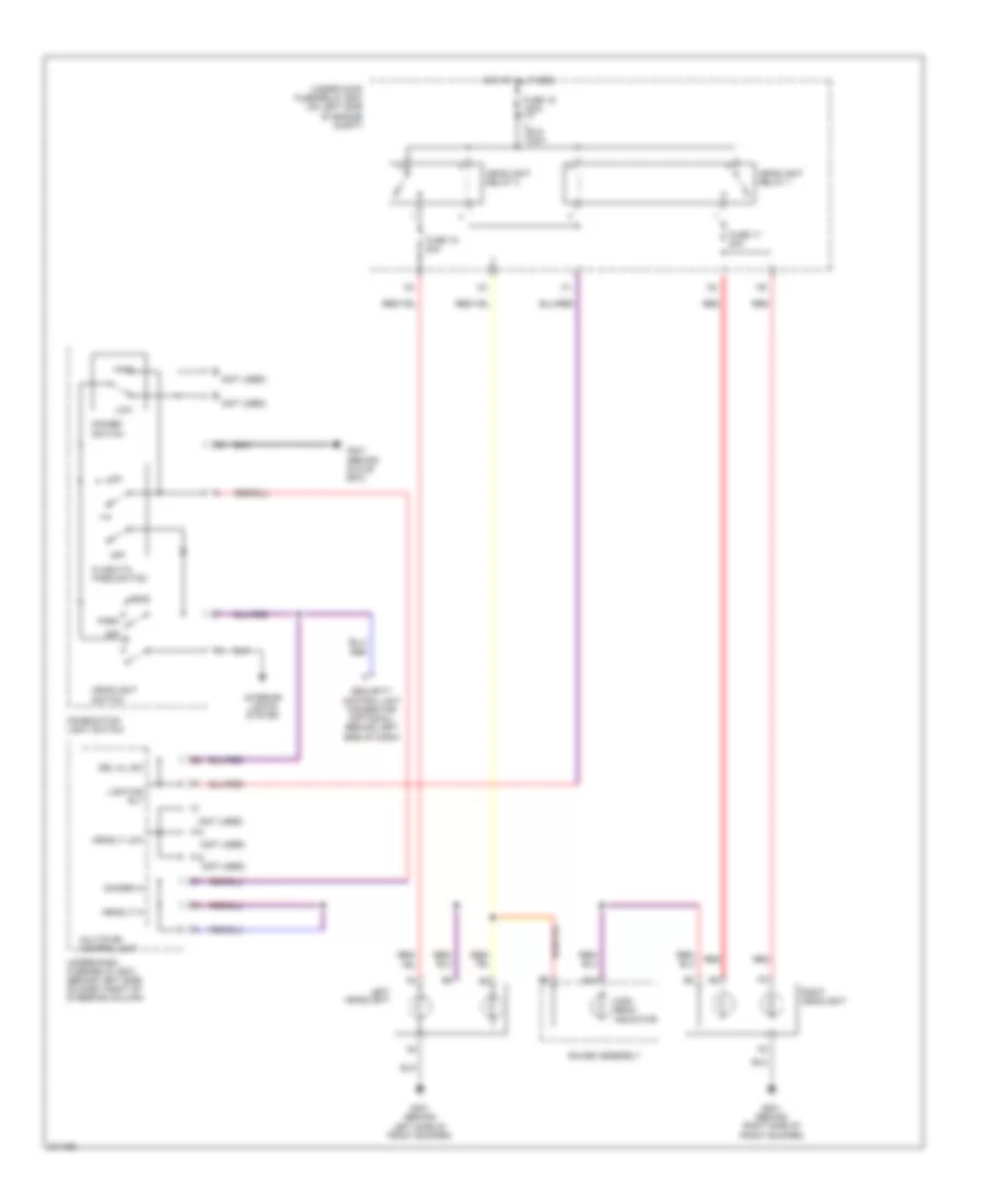
Headlights Wiring Diagram, without DRL for Honda CR-V SE 2005
List of elements for Headlights Wiring Diagram, without DRL for Honda CR-V SE 2005:
- (not used)
- B14
- Combination light switch
- Dimmer hi
- Dimmer switch
- Drl h/l sw
- Eld unit
- F10
- F12
- Flash-to- pass switch
- Fuse 15 20a
- Fuse 17 20a
- Fuse 19 100a
- G201 (behind right side of front bumper)
- G301 (behind left side of front bumper)
- G401 (behind glove box)
- Gauge assembly
- Head
- Headlight relay 1
- Headlight relay 2
- Headlight switch
- Headlt hi
- Headlt low
- High
- High beam indicator
- Hot at all times
- Interior lights system
- Left headlight
- Lighting rly
- Low
- Multiplex control unit
- Off
- Park
- Red
- Right headlight
- Security control unit connector (optional) (behind left side of dash)
- Under-dash fuse/relay box (behind left side of dash, right of steering column)
- Under-hood fuse/relay box (on left side of engine compt)
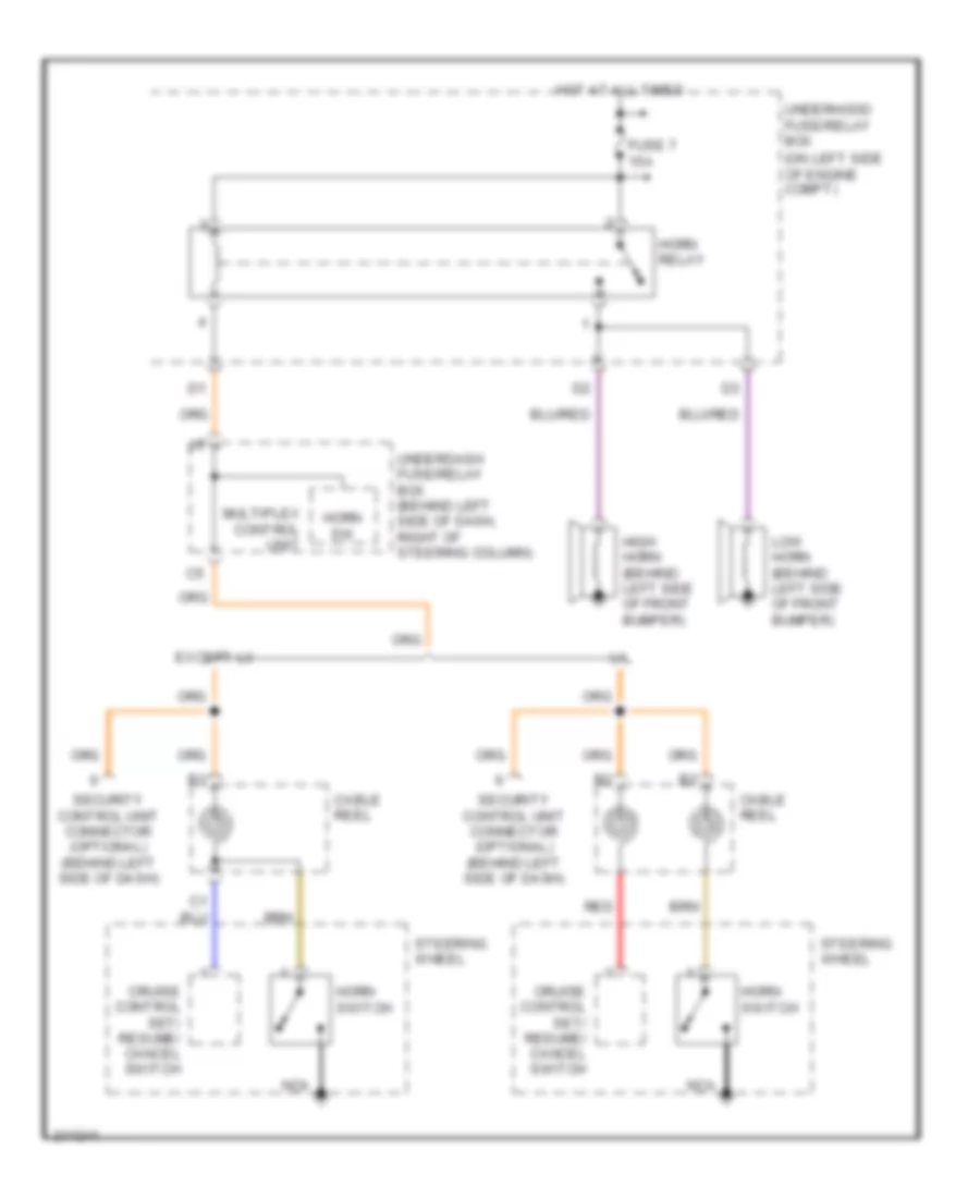
HORN
Horn Wiring Diagram for Honda CR-V SE 2005
List of elements for Horn Wiring Diagram for Honda CR-V SE 2005:
- (on left side of engine compt)
- Cable reel
- Cruise control set/ resume/ cancel switch
- Except lx
- Fuse 7 15a
- High horn (behind left side of front bumper)
- Horn relay
- Horn sw
- Horn switch
- Hot at all times
- Low horn (behind left side of front bumper)
- Multiplex control unit
- Nca
- Red
- Security control unit connector (optional) (behind left side of dash)
- Steering wheel
- Underdash fuse/relay box (behind left side of dash, right of steering column)
- Underhood fuse/relay box
INSTRUMENT CLUSTER
Instrument Cluster Wiring Diagram (1 of 2) for Honda CR-V SE 2005
List of elements for Instrument Cluster Wiring Diagram (1 of 2) for Honda CR-V SE 2005:
- (behind left side of dash, right of steering column) underdash fuse/relay box
- (behind left side of front bumper)
- (canada)
- (canada) drl ind
- (under right side of dash) g502
- A/t
- A10
- A11
- A12
- A13
- A14
- A15
- A16
- A17
- A18
- A19
- A20
- A21
- A22
- Abs indicator
- Abs indicator circuit
- Acc radio
- Act
- B10
- B11
- B12
- B13
- B14
- B15
- B16
- B17
- B18
- B19
- B20
- B21
- B22
- Beeper
- Brake fluid level switch (on brake fluid reservoir)
- Brake level sw
- Brake system indicator
- Bus (ecu)
- Bus meter
- Canada
- Charging system indicator
- Cpu
- Cruise control ind
- Cruise control system
- Dash lights brightness controller
- Door indicator light
- Drive circuit
- Drl control unit
- E10
- Exterior lights system
- Fuel gauge sending unit
- Fuel tank unit (in top of fuel tank)
- Fuse 10a
- Fuse 7.5a
- G101 (at left side of engine)
- G201 (behind right side of front bumper)
- G301
- G301 (behind left side of front bumper)
- G551 (under driver's seat)
- Gauge assembly
- Headlights system
- Hot in acc or on
- Hot in on or start
- Ig1 (meter)
- Immobilizer control unit receiver (on steering column, integral to ignition switch)
- Interior lights system
- J/c c105 (behind glove box)
- K10
- Left turn signal indicator
- Low fuel indicator
- Low oil pressure indicator
- Low washer fluid indicator (canada)
- M/t
- Maintenance required indicator
- Mil ind
- Multiplex control unit
- Oil pressure switch (on right front of engine, above oil filter)
- Outside air temperature sensor (except usa: lx)
- Parking brake switch (under left side of dash)
- Pnk
- Power circuit
- Red
- Right turn signal indicator
- Rxd
- Seat belt reminder indicator
- Side air bag cut-off ind
- Srs ind
- Srs indicator circuit
- Switch trip/reset
- Tailgate & hatch glass open indicator
- Transmissions system
- Txd
- Underdash fuse/relay box (behind left side of dash, right of steering column)
- Usa
- Vsa
- Vsa activation indicator
- Vsa diode (under middle of dash)
- Vsa ind
- Vsa indicator circuit
- Vsa modulator control unit (on right side of engine compt)
- Vss (on top of transmission)
- Washer fluid level switch (canada)
Instrument Cluster Wiring Diagram (2 of 2) for Honda CR-V SE 2005
List of elements for Instrument Cluster Wiring Diagram (2 of 2) for Honda CR-V SE 2005:
- (behind right side of dash)
- (except usa: lx)
- (usa)
- (vssout)
- A13
- A14
- A15
- A16
- A18
- A23
- B10
- B14
- B15
- B22
- Bus (sefmj)
- Coolant temperature gauge
- Cpu
- D11
- Dash lights brightness controller
- Dimming circuit
- Drive circuit
- Driver circuit
- E13
- E25
- E26
- E31
- Ecm/pcm
- Ect sensor (on rear of engine head)
- Engine controls system
- Fuel gauge
- Fuse 10a
- Gauge assembly
- High beam indicator
- Hot at all times
- Immobilizer system indicator
- Lcd back light
- Mil ctrl
- Odo/trip display
- Odo/trip lcd back light stabilizing power circuit
- Odo/trip/ outside air temperature display
- Rpm out (nep)
- Sensor input
- Sns gnd (sg2)
- Sns in (ect)
- Speedometer
- Tachometer
- Test tachometer connector (on left side of engine compt, near battery)
- Underdash fuse/relay box (behind left side of dash,right of steering column)
- Underhood fuse/relay box (on left side of engine compt)
INTERIOR LIGHTS
Courtesy Lamps Wiring Diagram for Honda CR-V SE 2005
List of elements for Courtesy Lamps Wiring Diagram for Honda CR-V SE 2005:
- (behind glove box)
- Door
- Driver's door lock knob switch
- Driver's door switch (on left "b" pillar)
- Ex; usa: se canada: ex-l
- Fr door sw
- Front ceiling light
- Front passenger's door switch (right "b" pillar)
- Fuse 3 15a
- G401
- G501 (under left side of dash)
- Hatch glass latch switch 2 (on middle of tailgate)
- Hot at all times
- Ignition key light
- Ignition key switch
- Ignition key switch/ key light
- Int lts
- Key sw
- Keyless com d/l sil-con sw (lock) key lt-
- Keyless receiver unit (under middle of dash)
- Left rear door switch (left "c" pillar)
- Multiplex control unit
- Off
- Other door sw
- P18
- Rear ceiling light
- Rear ceiling light diode (under right side of dash)
- Red
- Right rear door switch (right "c" pillar)
- Security control unit connector (optional) (behind left side of dash)
- Spotlights
- Tailgate switch (left side of tailgate)
- Trunk sw
- Underdash fuse/relay box (behind left side of dash, right of steering column)
- Underhood fuse/relay box (on left side of engine compartment)
Instrument Illumination Wiring Diagram for Honda CR-V SE 2005
List of elements for Instrument Illumination Wiring Diagram for Honda CR-V SE 2005:
- (in underdash fuse/relay box)
- A19
- Audio unit (behind center of dash)
- B15
- C11
- Coin pocket light
- Combination light switch
- Cpu
- Cruise control main switch
- Ex, usa: se
- Front ashtray light (a/t)
- Front passenger's air bag cut off indicator
- Fuse 15a
- G401 (behind glove box)
- G502 (under right side of dash)
- Gauge assembly
- Glove box light
- Hazard warning switch
- Head
- Headlight switch
- Heater control unit panel
- Hot at all times
- K11
- K17
- L10
- Lcd back light
- M/t
- Moonroof switch
- Multiplex control unit
- O10
- Odo/trip lcd back light stabilizing power circuit
- Off
- Park
- Power mirror switch
- Red
- Seat heater switch
- Security control unit connector (optional) (behind left side of dash)
- Small lt rly-
- Taillight relay
- Under hood fuse/ relay box (on left side of engine compt)
- Underdash fuse/relay box (behind left side of dash, right of steering column)
- Usa: ex, se; canada: ex-l
POWER DISTRIBUTION
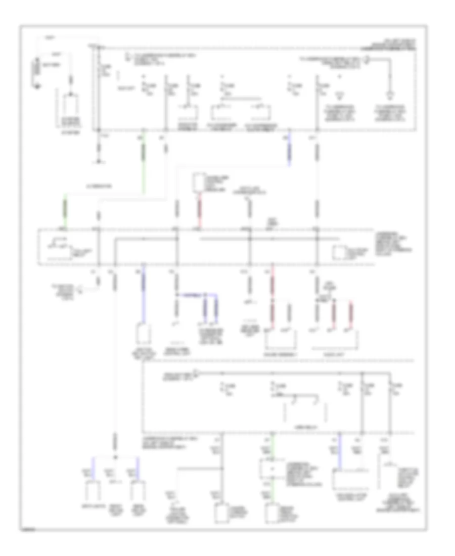
Power Distribution Wiring Diagram (1 of 4) for Honda CR-V SE 2005
List of elements for Power Distribution Wiring Diagram (1 of 4) for Honda CR-V SE 2005:
- (not used)
- (on left side of engine compartment) underhood fuse/relay box
- A/c compressor clutch relay
- A/c condenser fan relay
- A10
- A19
- Alternator
- Audio unit
- Auxiliary underhood fuse/relay box (left side of engine compartment)
- B10
- Battery
- Brake pedal position switch
- C10
- D11
- Data link connector (dlc)
- E12
- Eld unit
- From battery a (diagram 1 of 4)
- Front ceiling light
- Fuse 100a
- Fuse 10a
- Fuse 15a
- Fuse 20a
- Fuse 30a
- Fuse 50a
- Gauge assembly
- Hazard warning switch
- Horn relay
- Ignition key switch/ key light
- Immobilizer control unit- receiver
- K13
- Keyless receiver unit
- Multiplex control unit
- O12
- Radiator fan relay
- Rear ceiling light
- Rear wiper control unit
- Spotlights
- Starter
- Starter solenoid
- T101
- Taillight relay
- Throttle actuator control module relay
- To ignition switch (diagram 3 of 4)
- To underhood fuse/relay box (fuse 13, 40a) (diagram 2 of 4)
- To underhood fuse/relay box (fuse 2, 30a) (diagram 4 of 4)
- To underhood fuse/relay box (fuse 5, 15a) (diagram 1 of 4)
- To underhood fuse/relay box (headlight relay 2) (diagram 2 of 4)
- Trailer lighting connector (optional)
- Underdash fuse/relay box (behind left side of dash, right of steering column)
- Underhood fuse/relay box (on left side of engine compartment)
- Usa: ex, se
- Vsa modulator control unit
- Xm receiver connector (optional) (usa: ex, se)
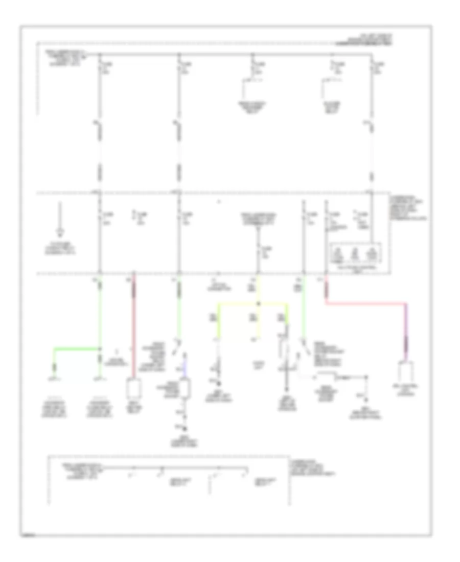
Power Distribution Wiring Diagram (2 of 4) for Honda CR-V SE 2005
List of elements for Power Distribution Wiring Diagram (2 of 4) for Honda CR-V SE 2005:
- (behind left side of dash, right of steering column)
- (on left side of engine compartment) under-hood fuse/relay box
- +b day lt/fr fog
- +b door lock
- +b rr fog
- Audio unit
- Blower motor relay
- Drl control unit (canada)
- From under-dash fuse/relay box (diagram 3 of 4)
- From under-hood fuse/relay box b (fuse 9, 10a) (diagram 1 of 4)
- From under-hood fuse/relay box c (fuse 6, 15a) (diagram 1 of 4)
- Front accessory power socket
- Front accessory power socket relay (under left side of dash)
- Fuse (not used)
- Fuse 10a
- Fuse 10a (canada)
- Fuse 15a
- Fuse 20a
- Fuse 40a
- G451 (left of center console)
- G501 (under left side of dash)
- G502 (under right side of dash)
- G601 (behind right quarter panel)
- Headlight relay 1
- Headlight relay 2
- Moonroof close relay (usa ex, se, canada ex-l)
- Moonroof open relay (usa ex, se, canada ex-l)
- Multiplex control unit
- Option connector
- Rear accessory power socket
- Rear accessory power socket relay (behind right side of dash)
- Rear window defogger relay
- Seat heater relay
- To power window relay (diagram 4 of 4)
- Under-dash fuse/relay box
- Under-hood fuse/relay box (on left side of engine compartment)
- Usa:se, canada ex-l
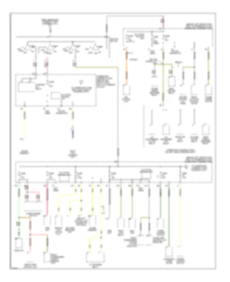
Power Distribution Wiring Diagram (3 of 4) for Honda CR-V SE 2005
List of elements for Power Distribution Wiring Diagram (3 of 4) for Honda CR-V SE 2005:
- (behind left side of dash, right of steering column) under-dash fuse/relay box
- (not used)
- A/c compressor clutch relay
- A/c condenser fan relay
- A/t
- A/t reverse relay
- A13
- A17
- A18
- Acc
- B4 red/
- Backup light switch (m/t)
- Blower motor relay
- Canada
- D11
- D12
- Drl control unit
- Ecm/ pcm
- From under-dash fuse/relay box (diagram 1 of 4)
- Front passenger's air bag cut-off indicator
- Front passenger's weight sensor unit
- Fuse (not used)
- Fuse 10a
- Fuse 15a
- Fuse 20a
- Fuse 7.5a
- Gauge assembly
- Hazard warning switch
- Heater control unit panel
- Ignition switch
- Immobilizer control unit receiver
- K12
- K14
- Keyless receiver unit
- Lock off
- Multiplex control unit
- Opds unit
- Option connector
- P12
- Pgm-fi main relay
- Power mirror defogger relay
- Power mirror switch
- Radiator fan relay
- Rear window defogger relay
- Rear wiper control unit
- Recir- culation control motor
- Se, ex-l
- Seat heater relay
- Security control unit connector (optional)
- Shift lock solenoid (a/t)
- Srs unit
- Start
- Starter cut relay
- To under-dash fuse/relay box (diagram 4 of 4)
- To under-dash fuse relay box fuse 18 (diagram 2 of 4)
- Under-dash fuse/relay box (behind left side of dash, right of steering column)
- Under-hood fuse/relay box (on left side of engine compt)
- Usa: se, canada: ex, ex-l
- Windshield wiper motor
- Wiper/ washer switch
- Wiper/washer switch
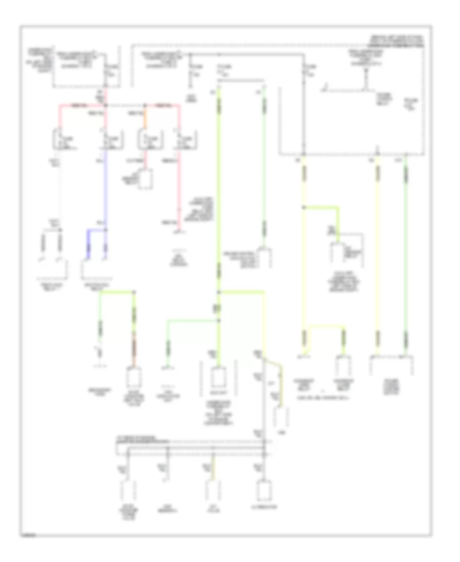
Power Distribution Wiring Diagram (4 of 4) for Honda CR-V SE 2005
List of elements for Power Distribution Wiring Diagram (4 of 4) for Honda CR-V SE 2005:
- (at rear of engine) junction connector c103
- (behind left side of dash, right of steering column) under-dash fuse/relay box
- (not used)
- (usa: ex, se, canada: ex-l)
- A/f sensor relay
- Alternator
- Auxiliary under-hood fuse/ relay box (left side of engine compt)
- Auxiliary under-hood fuse/relay box (left side of engine compt)
- Cmp sensor a
- Cruise control main switch/ vsa off switch
- Drl relay (canada)
- Eld unit
- Evap canister purge valve
- Evap canister vent shut valve
- From under-dash fuse/relay box fuse 7 (diagram 2 of 4)
- From under-dash g fuse/relay box fuse 19 (diagram 3 of 4)
- From under-hood h fuse/relay box fuse 9 (diagram 1 of 4)
- Fuse 10a
- Fuse 15a
- Fuse 20a
- Fuse 30a
- Fuse 7.5a
- Ignition coil relay
- Imt valve
- M/t
- M10
- Moonroof close relay
- Moonroof open relay
- Pgm-fi main relay 1
- Power window master switch
- Power window relay
- Secondary ho2s
- Under-hood fuse/relay box (on left side of engine compartment)
- Under-hood fuse/relay box (on left side of engine compt)
- Vsa modulator unit
- Vss
POWER DOOR LOCKS
Power Door Locks Wiring Diagram for Honda CR-V SE 2005
List of elements for Power Door Locks Wiring Diagram for Honda CR-V SE 2005:
- (under right side of dash)
- Back up (b+)
- D11
- D14
- Door lock (b+)
- Driver's door lock actuator (in driver's door)
- Driver's door lock knob switch (in rear of driver's door)
- Driver's door lock switch
- Driver's door switch (on left "b" pillar)
- Fr door sw (dr)
- Front passenger's door lock actuator (in front passenger's door)
- Front passenger's door lock switch
- Front passenger's door switch (on right "b" pillar)
- Fuse 10a
- Fuse 20a
- Fuse 7.5a
- G301 (behind left side of front bumper)
- G401 (behind glove box)
- G501 (under left side of dash)
- G502
- G502 (under right side of dash)
- Ground
- Horn sw
- Horns system
- Hot at all times
- Hot in on or start
- Ignition key switch
- Ignition key switch/key
- K13
- Key sw
- Keyless com
- Keyless receiver unit (under middle of dash)
- Left rear door lock actuator (in left rear door)
- Left rear door switch (on left "c" pillar)
- Light
- Lock
- Multiplex control unit
- Other door sw
- P16
- P17
- P18
- Rear ceiling light diode (under right side of dash)
- Red
- Right rear door lock actuator
- Right rear door switch (on right "c" pillar)
- Security control unit connector (optional) (behind left side of dash)
- Tailgate lock actuator (in tailgate)
- Tailgate switch (on left side of tailgate)
- Trunk switch
- Under-dash fuse/relay box (behind left side of dash, right of steering column)
- Under-hood fuse/relay box (on left side of engine compartment)
- Unlock
- Y10
- Y12
POWER MIRRORS
Power Mirrors Wiring Diagram for Honda CR-V SE 2005
List of elements for Power Mirrors Wiring Diagram for Honda CR-V SE 2005:
- 10a
- Canada: ex, ex-l; usa: se
- Defogger
- Defogger system
- Fuse 14
- G501 (under left side of dash)
- Hot in on
- Interior lights system
- Left
- Left down
- Left power mirror
- Left up
- Left/ right motor
- Lx; usa: ex
- Power mirror switch
- Power mirror switch light
- Red
- Right
- Right down
- Right power mirror
- Right up
- Switch 1
- Switch 2
- Switch 3
- Underdash fuse/relay box (behind left side of dash, right of steering column)
- Up/ down motor
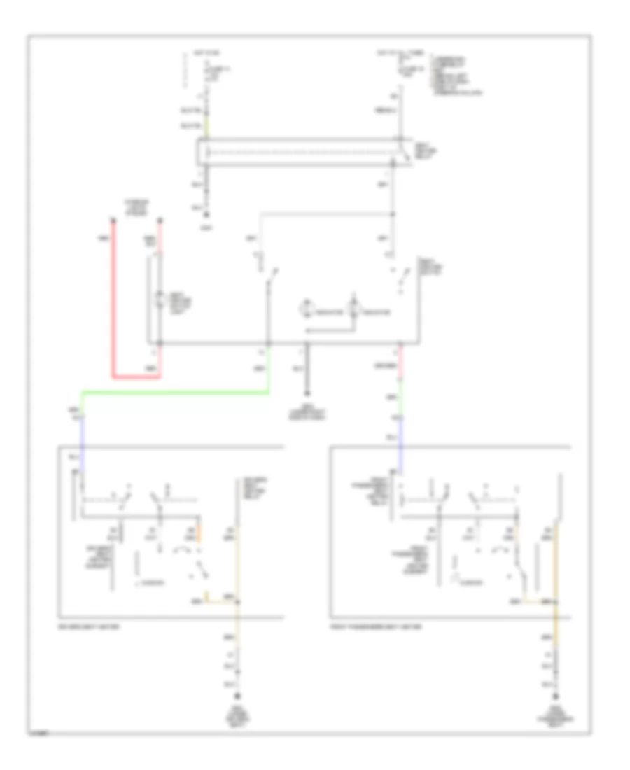
POWER SEATS
Power Seats Wiring Diagram for Honda CR-V SE 2005
List of elements for Power Seats Wiring Diagram for Honda CR-V SE 2005:
- Cushion
- Driver's seat heater
- Driver's seat heater element
- Driver's seat heater relay
- Front passenger's seat heater
- Front passenger's seat heater element
- Front passenger's seat heater relay
- Fuse 14 10a
- Fuse 16 20a
- G451
- G502 (under right side of dash)
- G551 (under driver's seat)
- G552 (under passenger's seat)
- Hot at all times
- Hot in on
- Indicator
- Interior lights system
- Red
- Seat heater relay
- Seat heater switch
- Seat heater switch light
- Underdash fuse/relay box (behind left side of dash, right of steering column)
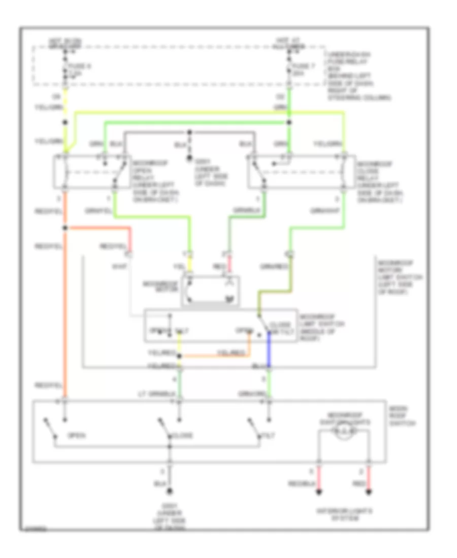
POWER TOP/SUNROOF
Power Top/Sunroof Wiring Diagram for Honda CR-V SE 2005
List of elements for Power Top/Sunroof Wiring Diagram for Honda CR-V SE 2005:
- Close
- Close or tilt
- Fuse 6 7.5a
- Fuse 7 20a
- G501 (under left side of dash)
- Hot at all times
- Hot in on or start
- Interior lights system
- Moon roof switch
- Moonroof close relay (under left side of dash, on bracket)
- Moonroof limit switch (middle of roof)
- Moonroof motor
- Moonroof motor/ limit switch (left side of roof)
- Moonroof open relay (under left side of dash, on bracket)
- Moonroof switch lights
- Open
- Open tilt
- Red
- Tilt
- Under-dash fuse/relay box (behind left side of dash, right of steering column)
POWER WINDOWS
Power Windows Wiring Diagram for Honda CR-V SE 2005
List of elements for Power Windows Wiring Diagram for Honda CR-V SE 2005:
- 40a
- Auto dn
- Auto up
- Driver's power window motor (in driver's door)
- Driver's switch
- Front passenger's power window motor (in right front door)
- Front passenger's power window switch
- Fuse 13
- Fuse 22 20a
- Fuse 23 20a
- Fuse 24 20a
- Fuse 25 20a
- Fuse 6 7.5a
- G301 (behind left side of front bumper)
- G501 (under left side of dash)
- Hot at all times
- Hot in on or start
- Left rear power window motor (in left rear door)
- Left rear power window switch
- M10
- M11
- Main switch
- Off
- P10
- P13
- Power window control unit
- Power window master switch
- Power window relay
- Pulser
- Red
- Right rear power window motor
- Right rear power window switch
- Underdash fuse/relay box (behind left side of dash, right of steering column)
- Underhood fuse/relay box (on left side of engine compt)
RADIO
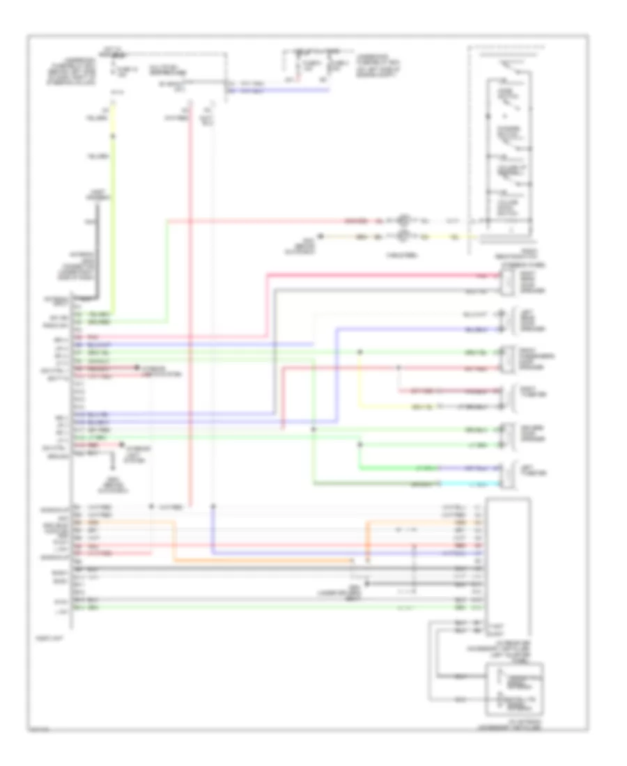
Radio Wiring Diagram, Except LX with Satellite Radio for Honda CR-V SE 2005
List of elements for Radio Wiring Diagram, Except LX with Satellite Radio for Honda CR-V SE 2005:
- (on left side of engine compt)
- +b back up
- A10
- A11
- A12
- A13
- A14
- A15
- A16
- A17
- A18
- A19
- A20
- Acc
- Antenna input
- Antenna lead connector (under right side of dash)
- Audio unit
- B+ back up
- B10
- B11
- B12
- B13
- B14
- Batt in
- Bus(+)
- Bus(-)
- Cable reel
- Channel switch
- D11
- Dim ctrl +
- Dim ctrl -
- Driver's door speaker
- Front passenger's door speaker
- Fuse 18 15a
- Fuse 3 15a
- Fuse 9 10a
- G401 (behind glove box)
- G503 (behind glove box)
- G551 (under driver's seat)
- Gnd (bus) audio sh gnd r ch+
- Ground
- Hot at all times
- Hot in acc or on
- Interior light system
- Interior lights system
- L ch+
- L ch-
- Left rear door speaker
- Left tweeter
- Lf (+)
- Lf (-)
- Lr (+)
- Lr (-)
- Mast antenna
- Mode switch
- Multiplex control unit
- Nca
- Pnk
- R ch-
- Radio remote switch
- Radio sw
- Red
- Rf (+)
- Rf (-)
- Right rear door speaker
- Right tweeter
- Rr (+)
- Rr (-)
- S-ant
- Satellite signal antenna
- Steering wheel
- Sw ign
- T-ant
- Terrestrial signal antenna
- Underdash fuse/relay box (behind left side of dash, right of steering column)
- Underhood fuse/relay box
- Volume down switch
- Volume up switch
- Xm antenna (accessory installed)
- Xm receiver (accessory installed) (left quarter panel)
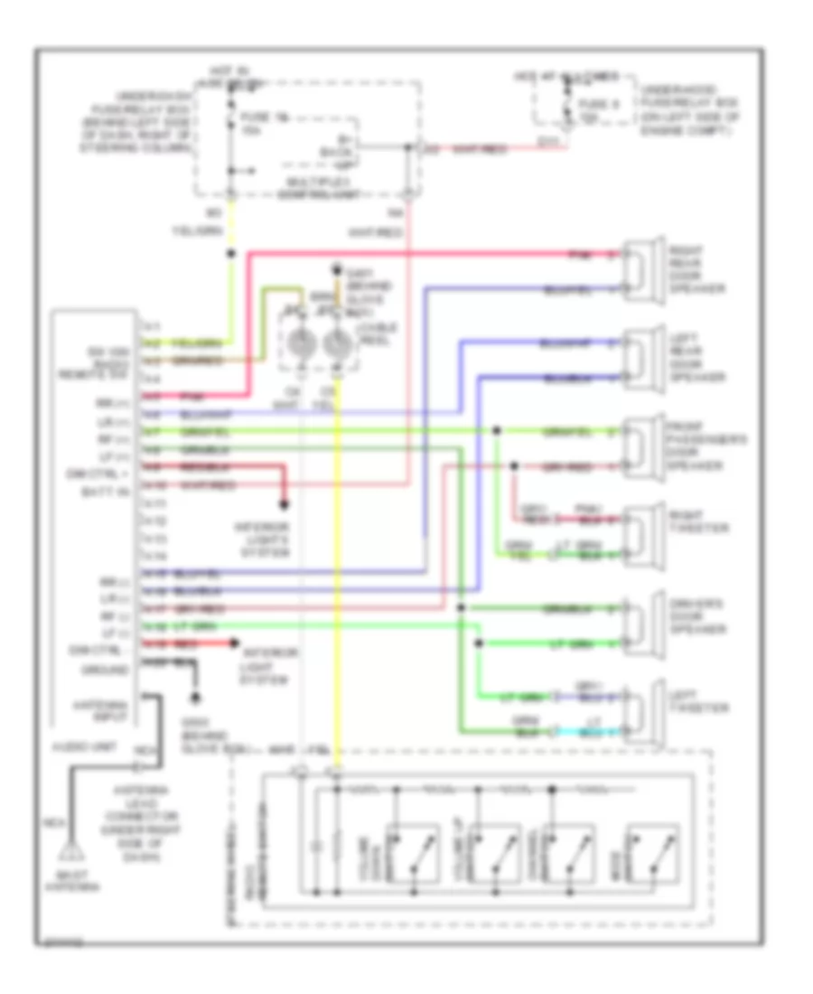
Radio Wiring Diagram, Except LX without Satellite Radio for Honda CR-V SE 2005
List of elements for Radio Wiring Diagram, Except LX without Satellite Radio for Honda CR-V SE 2005:
- (on left side of engine compt)
- A10
- A11
- A12
- A13
- A14
- A15
- A16
- A17
- A18
- A19
- A20
- Antenna input
- Antenna lead connector (under right side of dash)
- Audio unit
- B+ back up
- Batt in
- Cable reel
- D11
- Dim ctrl +
- Dim ctrl -
- Down switch
- Driver's door speaker
- Front passenger's door speaker
- Fuse 18 15a
- Fuse 9 10a
- G401 (behind glove box)
- G503 (behind glove box)
- Ground
- Hot at all times
- Hot in acc or on
- Interior
- Interior lights system
- Left rear door speaker
- Left tweeter
- Lf (+)
- Lf (-)
- Light system
- Lr (+)
- Lr (-)
- Mast antenna
- Mode switch
- Multiplex control unit
- Nca
- Pnk
- Radio remote switch
- Red
- Rf (+)
- Rf (-)
- Right rear door speaker
- Right tweeter
- Rr (+)
- Rr (-)
- Steering wheel
- Sw ign radio remote sw
- Switch channel
- Under-dash fuse/relay box (behind left side of dash, right of steering column)
- Under-hood fuse/relay box
- Volume
- Volume up switch
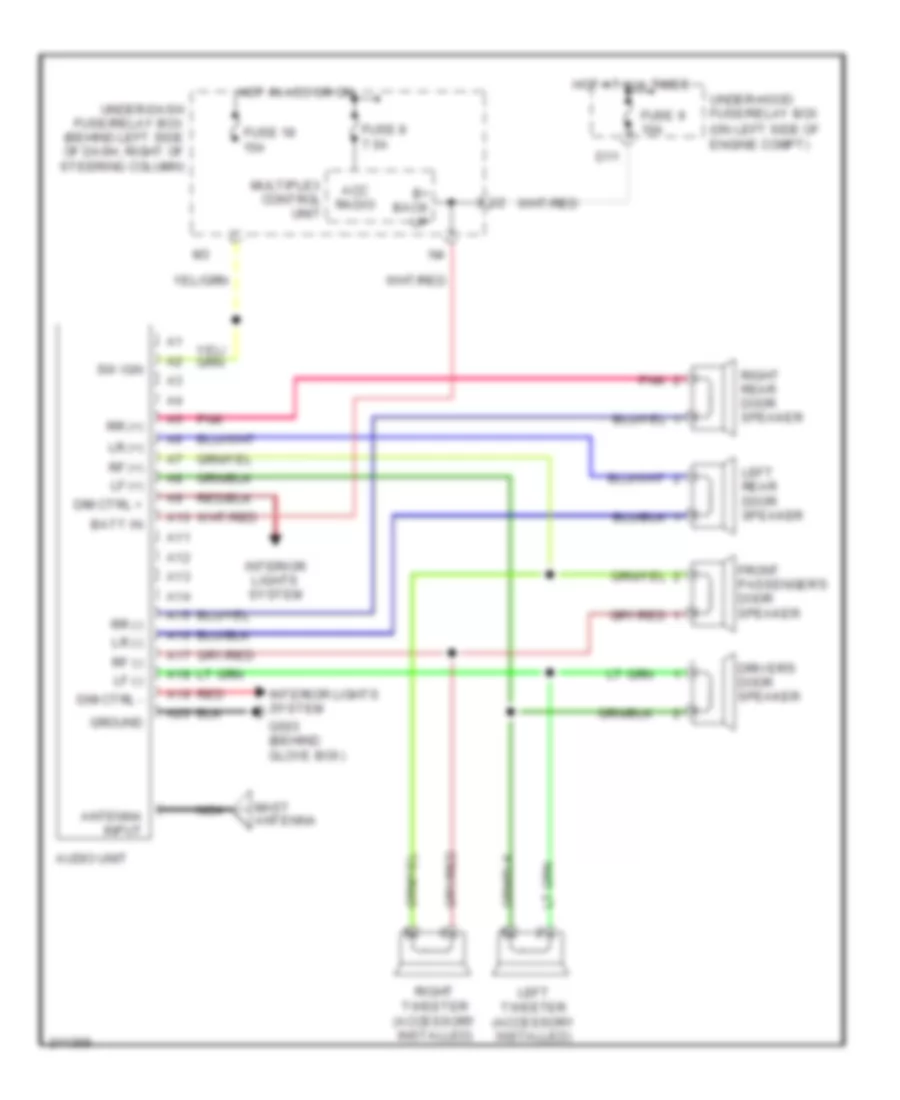
Radio Wiring Diagram, LX for Honda CR-V SE 2005
List of elements for Radio Wiring Diagram, LX for Honda CR-V SE 2005:
- (on left side of engine compt)
- A10
- A11
- A12
- A13
- A14
- A15
- A16
- A17
- A18
- A19
- A20
- Acc radio
- Antenna input
- Audio unit
- B+ back up
- Batt in
- D11
- Dim ctrl +
- Dim ctrl -
- Driver's door speaker
- Front passenger's door speaker
- Fuse 18 15a
- Fuse 8 7.5a
- Fuse 9 10a
- G503 (behind glove box)
- Ground
- Hot at all times
- Hot in acc or on
- Interior lights system
- Left rear door speaker
- Left tweeter (accessory installed)
- Lf (+)
- Lf (-)
- Lr (+)
- Lr (-)
- Mast antenna
- Multiplex control unit
- Nca
- Pnk
- Red
- Rf (+)
- Rf (-)
- Right rear door speaker
- Right tweeter (accessory installed)
- Rr (+)
- Rr (-)
- Sw ign
- Under-dash fuse/relay box (behind left side of dash, right of steering column)
- Under-hood fuse/relay box
SHIFT INTERLOCK
Shift Interlock Wiring Diagram for Honda CR-V SE 2005
List of elements for Shift Interlock Wiring Diagram for Honda CR-V SE 2005:
- (bksw) switch input
- (not used)
- Acc radio
- Atp -n
- Atpn
- Brake pedal position switch (behind dash, on brake pedal support)
- C20
- E22
- Fuse 15a
- Fuse 7.5a
- G10
- G101 (at left side of engine)
- G301 (behind left side of front bumper)
- G401 (behind glove box)
- Gauge assembly
- Gnd
- Hot at all times
- Hot in acc or on
- Hot in on or start
- Ig1 meter
- Ignition key switch
- Ignition key switch/ key light
- Junction connector c105 (behind glove box)
- Key interlock solenoid
- Key lock sol +
- Key sw
- Multiplex control unit
- O12
- P pin sw
- P-pinsw
- Park pin switch
- Pcm (behind right side of dash)
- Security control unit connector (optional) (behind left side of dash)
- Shift lock solenoid
- Sls
- Stop sw
- Transmission range switch (on lower rear of transaxle)
- Under-dash fuse/relay box (behind left side of dash, right of steering column)
- Under-hood fuse/relay box (on left side of engine compt)
STARTING/CHARGING
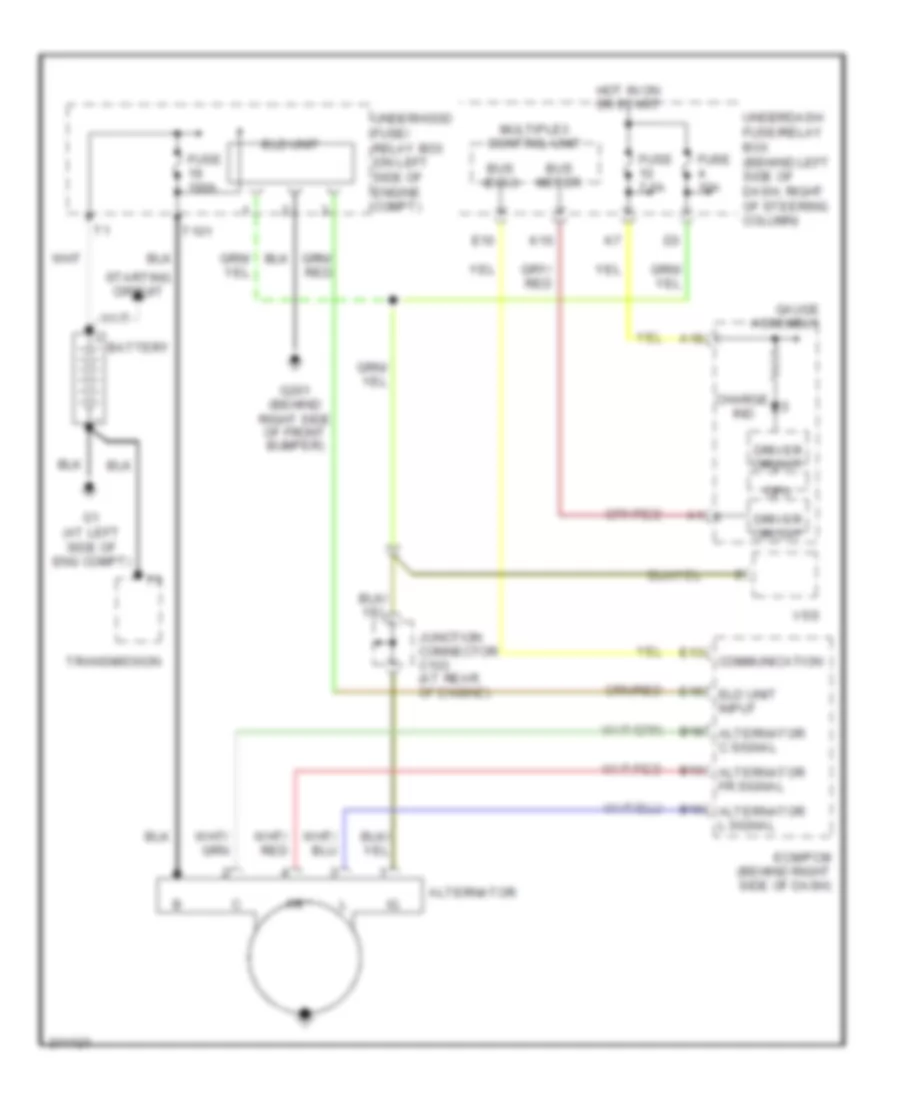
Charging Wiring Diagram for Honda CR-V SE 2005
List of elements for Charging Wiring Diagram for Honda CR-V SE 2005:
- A18
- Alternator
- B10 alternator l signal
- B13 alternator fr signal
- B18 alternator c signal
- Battery
- Bus (ecu)
- Bus meter
- Charge
- Communication
- Cpu
- Driver circuit
- E10
- E13
- E15 eld unit input
- Ecm/pcm (behind right side of dash)
- Eld unit
- Fuse 100a
- Fuse 10a
- Fuse 7.5a
- G1 (at left side of eng compt)
- G201 (behind right side of front bumper)
- Gauge assembly
- Hot in on or start
- Ind
- Junction connector c103 (at rear of engine)
- K10
- Multiplex control unit
- Starting circuit
- T101
- Transmission
- Underdash fuse/relay box (behind left side of dash, right of steering column)
- Underhood fuse/ relay box (on left side of engine compt)
- Vss
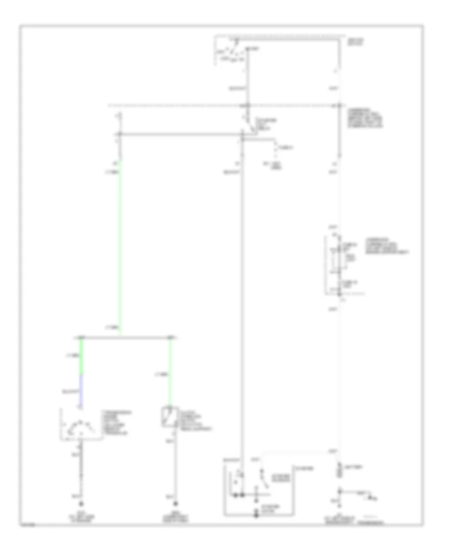
Starting Wiring Diagram for Honda CR-V SE 2005
List of elements for Starting Wiring Diagram for Honda CR-V SE 2005:
- (not used)
- A/t
- Acc
- Battery
- Clutch interlock switch (on clutch pedal support)
- E11
- Eld unit
- Fuse 19 100a
- Fuse 20 50a
- Fuse 21
- G1 (at left side of engine compt)
- G101 (at left side of engine)
- G502 (under right side of dash)
- Ignition switch
- Lock
- M/t
- Off
- Start
- Starter
- Starter cut relay
- Starter motor
- Starter solenoid
- Transmission
- Transmission range switch (on lower rear of transaxle)
- Underdash fuse/relay box (behind left side of dash, right of steering column)
- Underhood fuse/relay box (on left side of engine compartment)
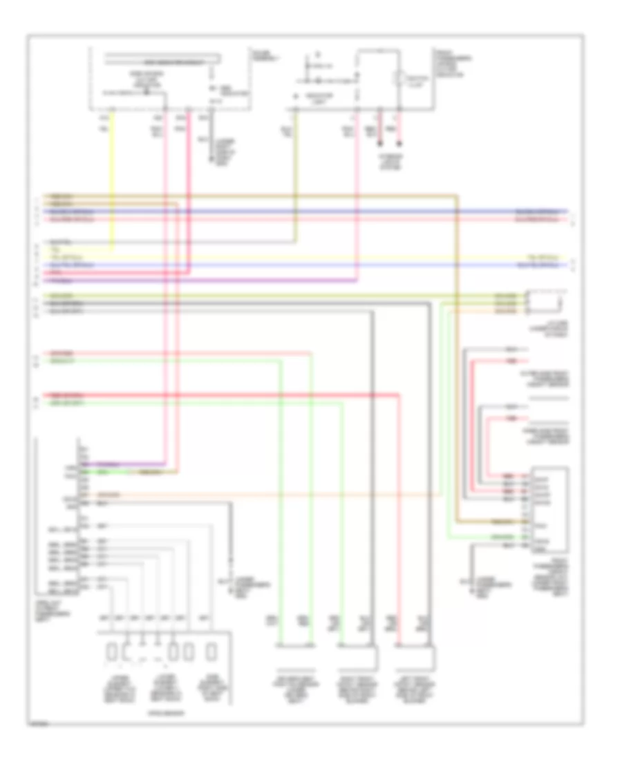
SUPPLEMENTAL RESTRAINTS
Supplemental Restraints Wiring Diagram (1 of 3) for Honda CR-V SE 2005
List of elements for Supplemental Restraints Wiring Diagram (1 of 3) for Honda CR-V SE 2005:
- (under driver's seat) g551
- (under middle of dash) g402
- (under middle of dash) g451
- (under passenger's seat) g552
- A10
- A11
- A12
- A13
- A14
- A15
- A16
- A17
- A18
- A19
- A20
- A21
- A22
- A23
- A24
- A25
- A26
- A27
- A28
- B10
- B11
- B12
- B13
- B14
- B15
- B16
- B17
- B18
- B19
- B20
- B21
- B22
- B23
- B24
- B25
- B26
- B27
- B28
- Bsdh
- Bsdl
- Bsph
- Bspl
- Buck- led
- Cable reel
- Check in
- Dlc (under left side of dash)
- Dr belt sw
- Driver's air bag first inflator
- Driver's air bag second inflator
- Driver's seat belt buckle tensioner (under driver's seat)
- Driver's seat belt switch (in driver's seat belt buckle)
- Driver's seat belt tensioner (at left "b" pillar)
- Front passenger's seat belt buckle tensioner (under front passenger's seat)
- Front passenger's seat belt switch (in front passenger's seat belt buckle)
- Front passenger's seat belt tensioner (at right "b" pillar)
- Frsc
- Frsr
- Fuse 10a
- Fuse 15a
- Fuse 7.5a
- Gnda
- Gndb
- Hot in on or start
- Ign in
- Ind ctrl
- K-line
- K14
- Lfs-
- Mes conn
- Mes connector (under left side of dash)
- Multiplex control unit
- Opds
- P12
- Pnk
- Red
- Rfs-
- Sadc1
- Sadc2
- Sadh1
- Sadh2
- Sapc1
- Sapc2
- Saph1
- Saph2
- Sblc
- Sblh
- Sbrc
- Sbrh
- Short contact
- Splc
- Splh
- Sprc
- Sprh
- Srs ind
- Srs unit (below center of dash)
- Ss+
- Ss-
- Steering wheel
- Un-
- Underdash fuse/relay box (behind left side of dash, right of steering column)
Supplemental Restraints Wiring Diagram (2 of 3) for Honda CR-V SE 2005
List of elements for Supplemental Restraints Wiring Diagram (2 of 3) for Honda CR-V SE 2005:
- (under passenger's seat) g552
- (under right side of dash) g502
- A18
- A20
- B15
- B16
- Driver's seat position sensor (under driver's seat)
- Front passenger's air bag cut-off indicator
- Front passenger's weight sensor unit (under front passenger's seat)
- Gauge assembly
- Gnd
- Indicator light
- Inner side front passenger's weight sensor
- Interior lights system
- J/c c456 (under middle of dash)
- Left front impact sensor (behind left side of front bumper)
- Lower element (lower 4 sensors in seat back)
- Odus
- Opds sensor
- Opds unit (in front passenger's seat)
- Outer side front passenger's weight sensor
- Pnk
- Pow
- Red
- Right front impact sensor (behind right side of front bumper)
- Sb1l, sb1s
- Sb2l, sb2s
- Sb3l, sb3s
- Sb4l, sb4s
- Sb5l, sb5s
- Sb6l, sb6s
- Side air bag cut-off indicator
- Side element (right side of seat back)
- Srs indicator
- Srs indicator circuit
- Ss1l, ss1s
- Swig
- Swip
- Switch illum
- Swog
- Swop
- Upper element (upper two sensors in seat back)
- Wrn
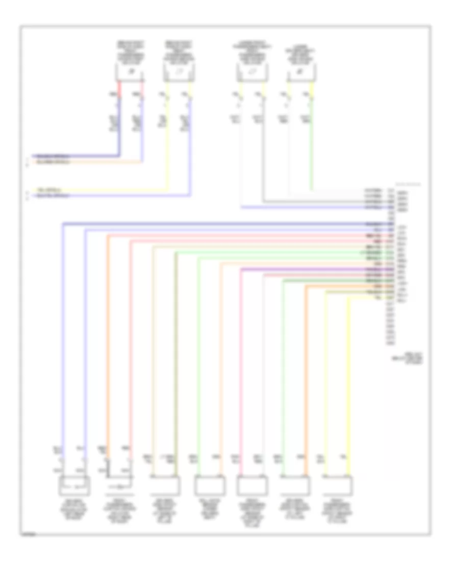
Supplemental Restraints Wiring Diagram (3 of 3) for Honda CR-V SE 2005
List of elements for Supplemental Restraints Wiring Diagram (3 of 3) for Honda CR-V SE 2005:
- (behind right side of dash) front passenger's air bag first inflator
- (behind right side of dash) front passenger's air bag second inflator
- (under driver's seat) driver's side air bag inflator
- (under front passenger's seat) front passenger's side air bag inflator
- C10
- C11
- C12
- C13
- C14
- C15
- C16
- C17
- C18
- C19
- C20
- C21
- C22
- C23
- C24
- C25
- C27
- C28
- Driver's curtain air bag inflator (left rear of roof)
- Driver's side curtain impact sensor (at left "c" pillar)
- Driver's side impact sensor (at base of left "b" pillar)
- Front passenger's curtain air bag inflator (right rear of roof)
- Front passenger's side curtain impact sensor (at right "c" pillar)
- Front passenger's side impact sensor (at base of right "b" pillar)
- Lca+
- Lca-
- Lcsi+
- Lcsi-
- Nca
- Rca+
- Rca-
- Rcli+
- Rcli-
- Red
- Roll rate sensor (under driver's seat)
- Rrs+
- Rrs-
- Sdc
- Sdv
- Spc
- Srs unit (below center of dash)
- Ssdc
- Ssdh
- Sspc
- Ssph
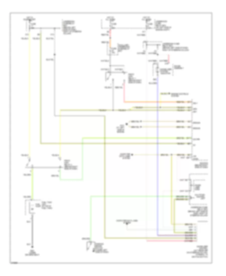
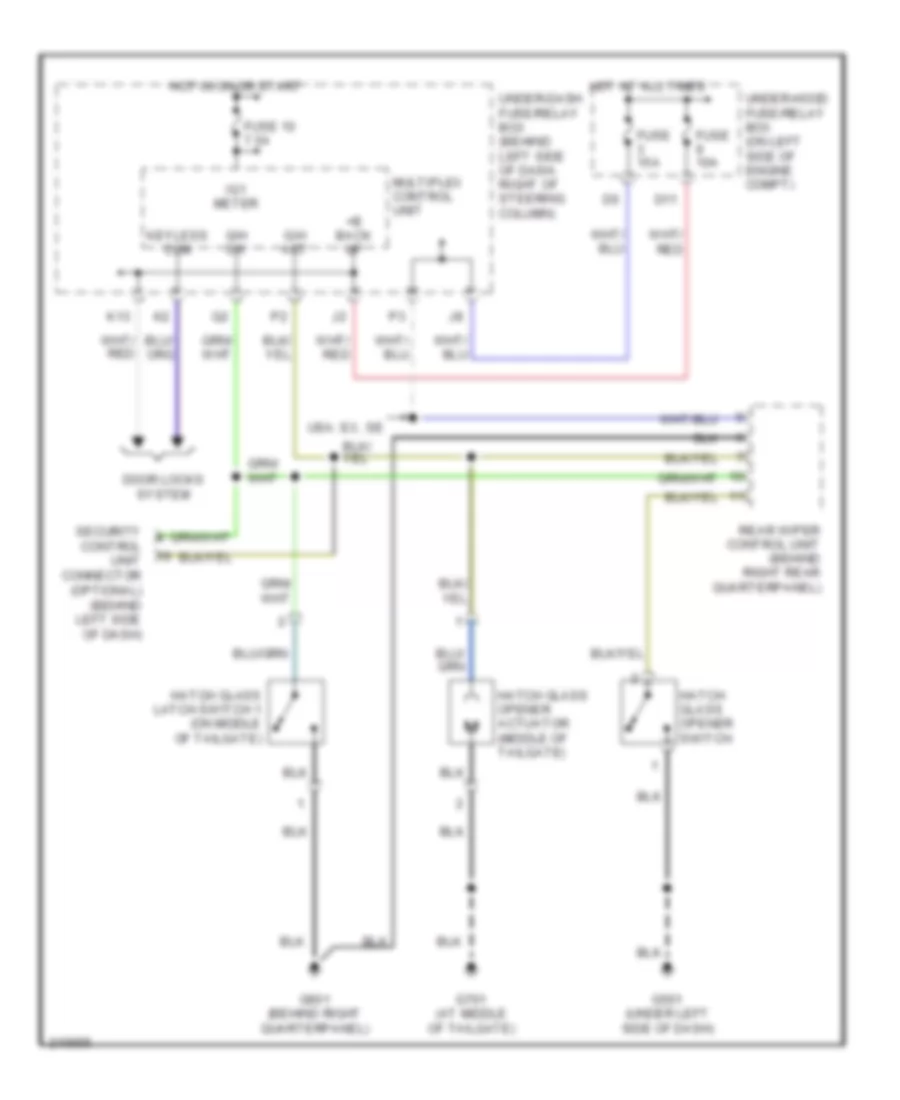
TRUNK, TAILGATE, FUEL DOOR
Liftglass Release Wiring Diagram for Honda CR-V SE 2005
List of elements for Liftglass Release Wiring Diagram for Honda CR-V SE 2005:
- +b back up
- D11
- Door locks system
- Fuse 10 7.5a
- Fuse 10a
- Fuse 15a
- G/h act
- G/h sw
- G501 (under left side of dash)
- G601 (behind right quarterpanel)
- G701 (at middle of tailgate)
- Hatch glass latch switch 1 (on middle of tailgate)
- Hatch glass opener actuator (middle of tailgate)
- Hatch glass opener switch
- Hot at all times
- Hot in on or start
- Ig1 meter
- K13
- Keyless com
- Multiplex control unit
- Rear wiper control unit (behind right rear quarterpanel)
- Security control unit connector (optional) (behind left side of dash)
- Under-dash fuse/relay box (behind left side of dash, right of steering column)
- Under-hood fuse/relay box (on left side of engine compt)
- Usa: ex, se
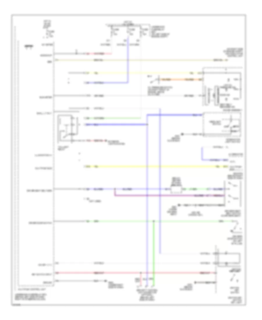
WARNING SYSTEMS
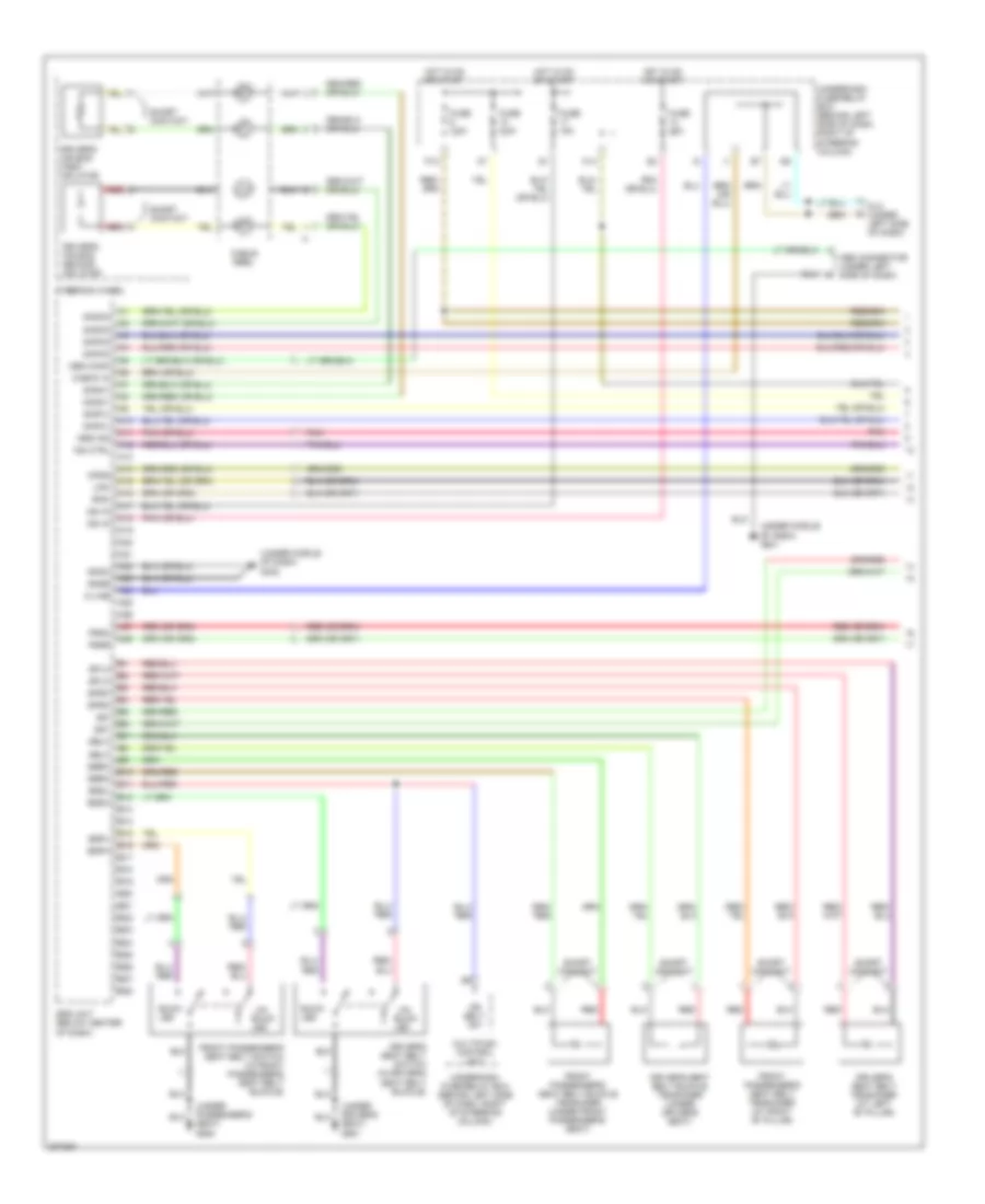
Warning Systems Wiring Diagram for Honda CR-V SE 2005
List of elements for Warning Systems Wiring Diagram for Honda CR-V SE 2005:
- (below center of dash) srs unit
- (ig) key lt (-)
- (not used)
- (on right side of engine compt) vsa modulator control unit
- +b backup
- A18
- Alternator
- Altl
- B10
- B11
- Beeper
- Bus meter
- C11
- Combination light switch
- Cpu
- D11
- Door ind
- Drive circuit
- Driver door switch
- Driver seat belt/srs
- Driver's door switch (on left "b" pillar)
- Driver's seat belt switch (in driver's seat)
- E10
- E13
- Ebd
- Ecm/pcm (behind right side of dash)
- Exterior lights system
- Fuse 10a
- Fuse 15a
- Fuse 7.5a
- G401 (behind glove box)
- G502 (under right side of dash)
- G551 (under driver's seat)
- Gauge assembly
- Ground
- Head
- Headlight switch
- Hot at all times
- Hot in on or start
- Ig1 meter
- Ignition key light
- Ignition key switch
- Ignition key switch/ key light
- Illumination (+)
- K10
- Key switch input
- Low oil
- Multiplex bus
- Multiplex control unit
- Off
- Oil pressure switch (on right front of engine, above oil filter)
- P15
- Park
- Pressure ind
- Seat belt reminder ind
- Security control unit connector (optional) (behind left side of dash)
- Small lt rly-
- Taillight relay
- Underdash fuse/relay box (behind left side of dash, right of steering column)
- Underhood fuse/relay box (on left side of engine compt)
- Usa: se canada: ex-l
WIPER/WASHER
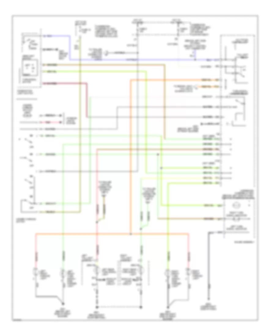
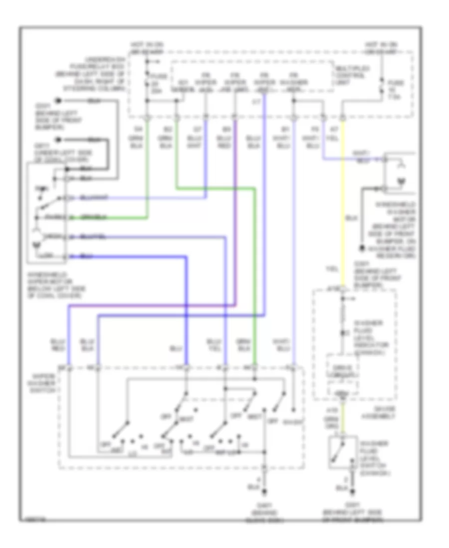
Front Wiper/Washer Wiring Diagram for Honda CR-V SE 2005
List of elements for Front Wiper/Washer Wiring Diagram for Honda CR-V SE 2005:
- A10
- A18
- Cpu
- Drive circuit
- Fr washer mtr
- Fr wiper (as)
- Fr wiper (int)
- Fr wiper int unit
- Fuse 20a
- Fuse 7.5a
- G301 (behind left side of front bumper)
- G401 (behind glove box)
- G811 (under left side of cowl cover)
- Gauge assembly
- High
- Hot in on or start
- Ig1 wiper
- Int
- Low
- Mist
- Multiplex control unit
- Off
- Park
- Run
- Underdash fuse/relay box (behind left side of dash, right of steering column)
- Wash
- Washer fluid level indicator (canada)
- Washer fluid level switch (canada)
- Windshield washer motor (behind left side of front bumper, on washer fluid reservoir)
- Windshield wiper motor (below left side of cowl cover)
- Wiper/ washer switch
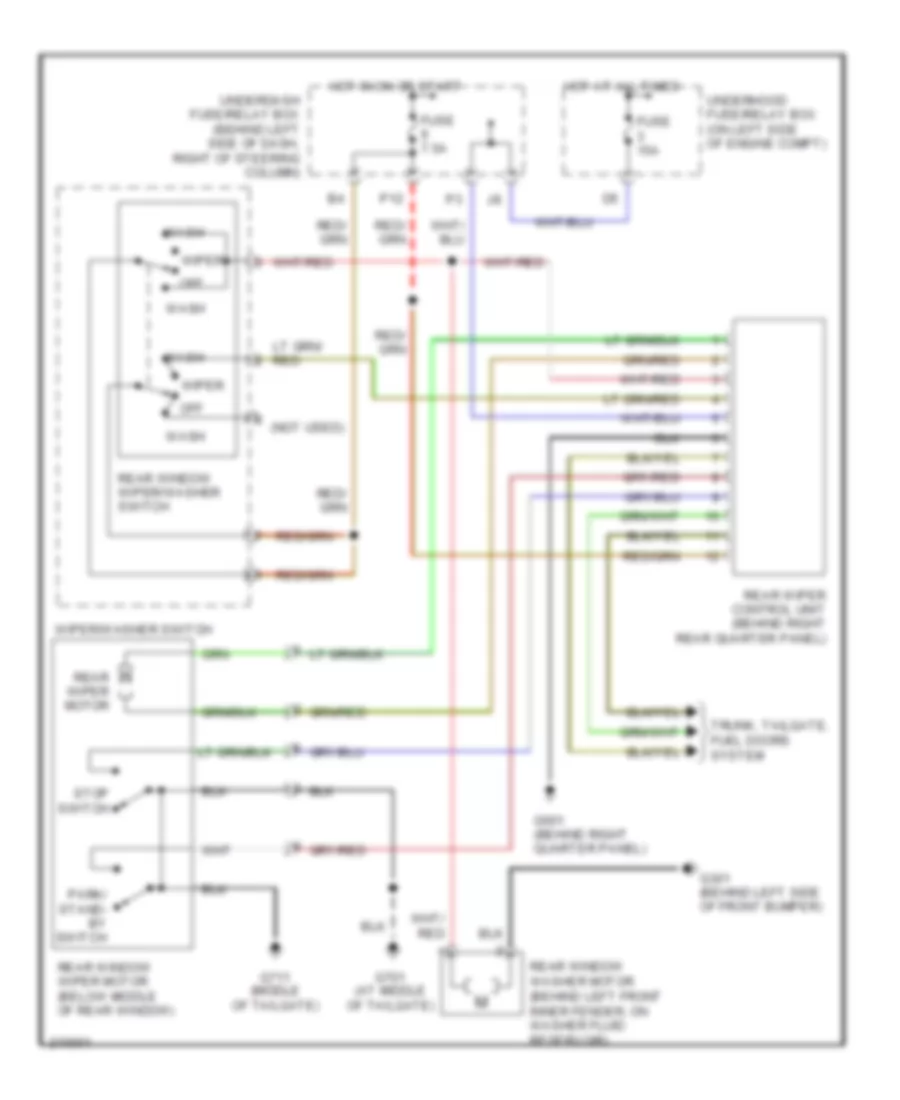
Rear Wiper/Washer Wiring Diagram for Honda CR-V SE 2005
List of elements for Rear Wiper/Washer Wiring Diagram for Honda CR-V SE 2005:
- (not used)
- Fuse 15a
- Fuse 7.5a
- G301 (behind left side of front bumper)
- G601 (behind right quarter panel)
- G701 (at middle of tailgate)
- G711 (middle of tailgate)
- Hot at all times
- Hot in on or start
- Off
- P12
- Park/ stand- by switch
- Rear window washer motor (behind left front inner fender, on washer fluid reservoir)
- Rear window wiper motor (below middle of rear window)
- Rear window wiper/washer switch
- Rear wiper control unit (behind right rear quarter panel)
- Rear wiper motor
- Stop switch
- Trunk, tailgate, fuel doors system
- Underdash fuse/relay box (behind left side of dash, right of steering column)
- Underhood fuse/relay box (on left side of engine compt)
- Wash
- Wiper
- Wiper/washer switch

 Čeština
 Dansk
Dansk Deutsch
 Ελληνικά
 English
 English
 Español
 Suomi
Suomi Français
 Français
 עברית
עברית Hrvatski
 Magyar
 日本語
日本語 한국어
한국어 Nederlands
 Polski
 Português
 Português
 Română
 Русский
 Slovenčina
 Slovenščina
 Svenska
 Türkçe
 中文 (中国)