AIR CONDITIONING
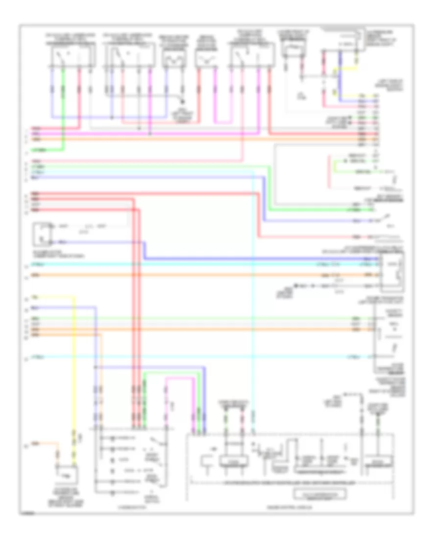
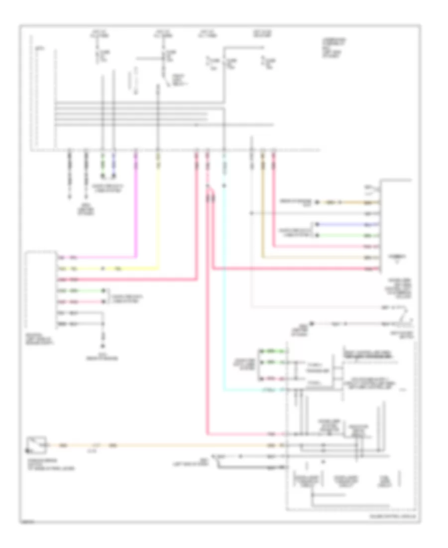
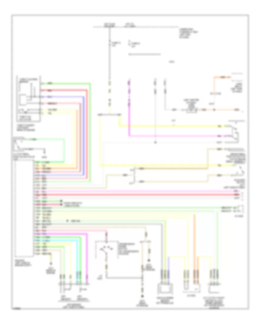
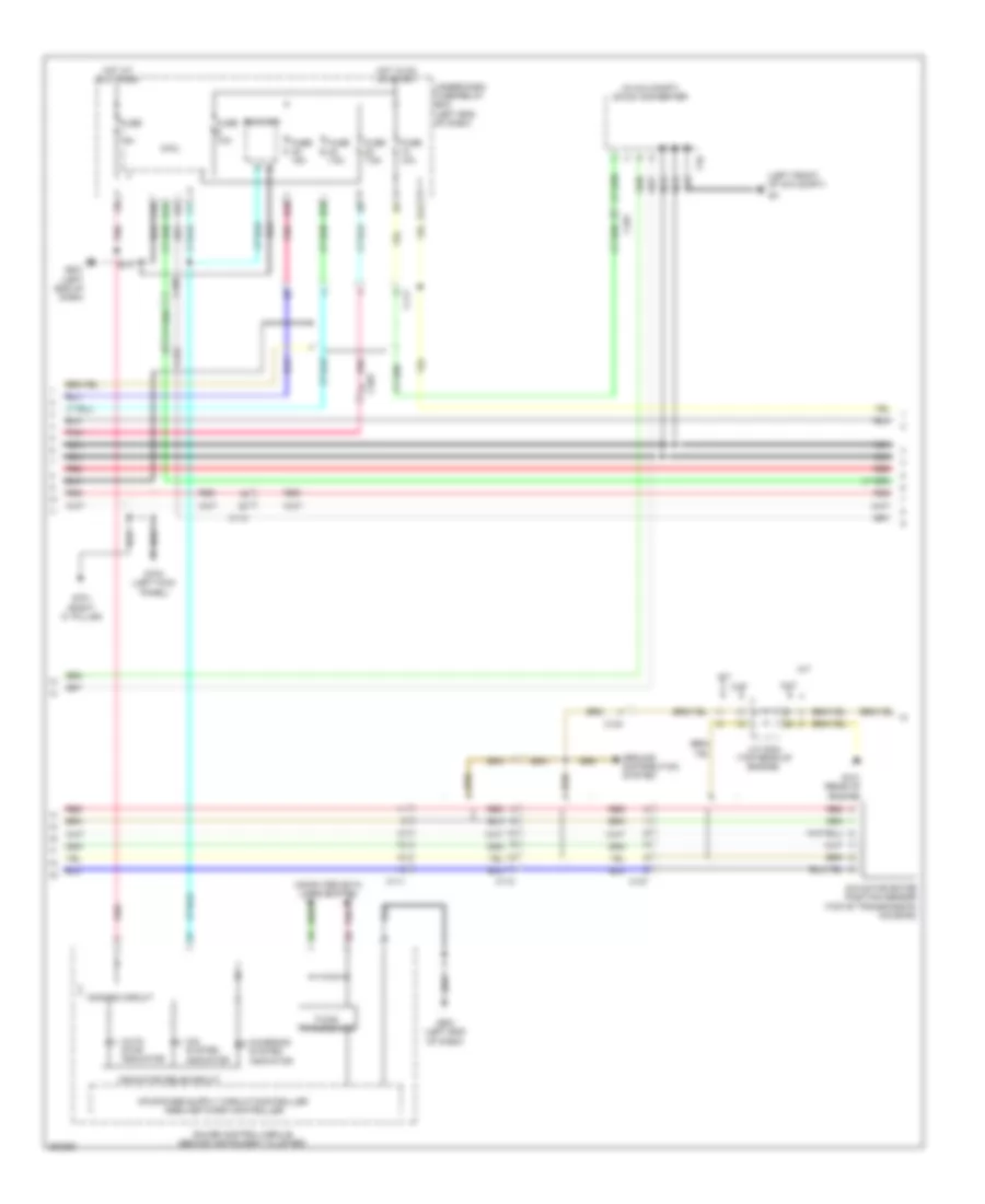
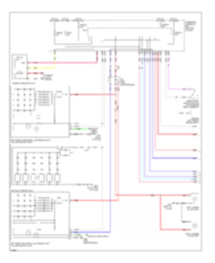
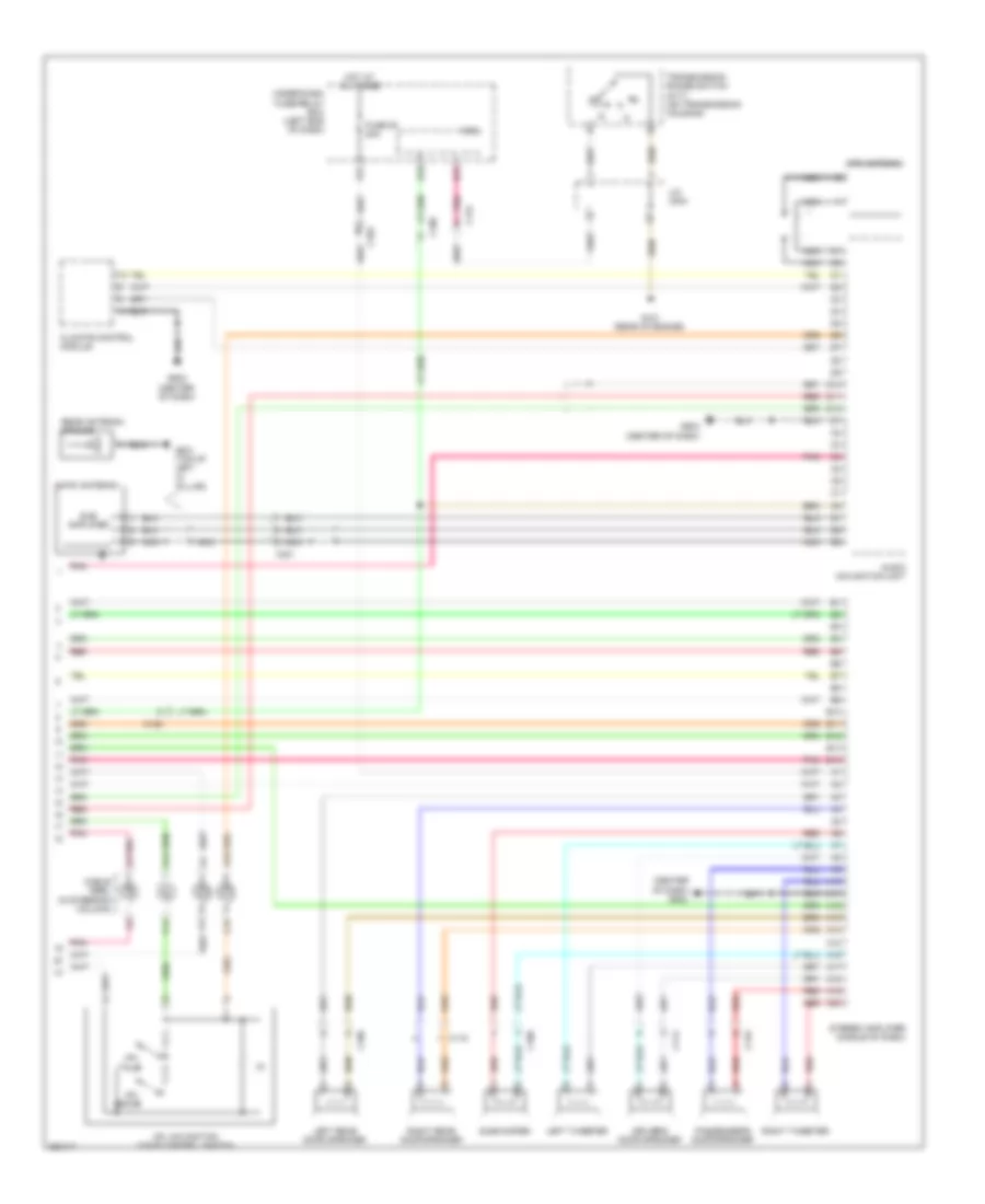
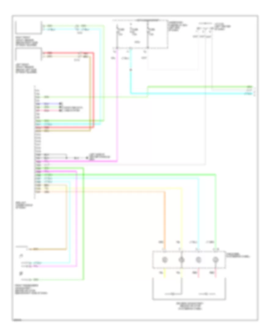
Automatic A/C Wiring Diagram (1 of 2) for Honda CR-Z EX 2012
 https://portal-diagnostov.com/license.html
Automotive Electricians Portal FZCO
Automotive Electricians Portal FZCO
https://portal-diagnostov.com/license.html
https://portal-diagnostov.com/license.html
Automotive Electricians Portal FZCO
Automotive Electricians Portal FZCO
List of elements for Automatic A/C Wiring Diagram (1 of 2) for Honda CR-Z EX 2012:
- A/c compressor clutch (left front of engine)
- A/c diode a
- A/c diode b
- A/f sensor relay
- Ab3
- Air mix control motor
- Automatic lighting/ sunlight sensor (top right side of dash)
- B10
- B24
- B33
- B34
- Blower motor relay
- C102
- C103
- C117
- C122
- Climate control unit
- Computer data lines system
- Defogger system
- Evaporator temperature sensor (upper right side of dash)
- Fuse 10 7.5a
- Fuse 26 10a
- Fuse 29 10a
- Fuse 30a
- Fuse 31 7.5a
- Fuse 57 30a
- Fuse 7.5a
- G501 (left end of dash)
- G502 (center of dash)
- Hot at all times
- Hot in on
- Hot in on or start
- Micu
- Mode control motor
- Mode control motor (upper left side of hvac assembly)
- Navigation system
- Pnk
- Recirculation control motor
- Red
- Under-dash fuse/relay box (left end of dash)
- Y11
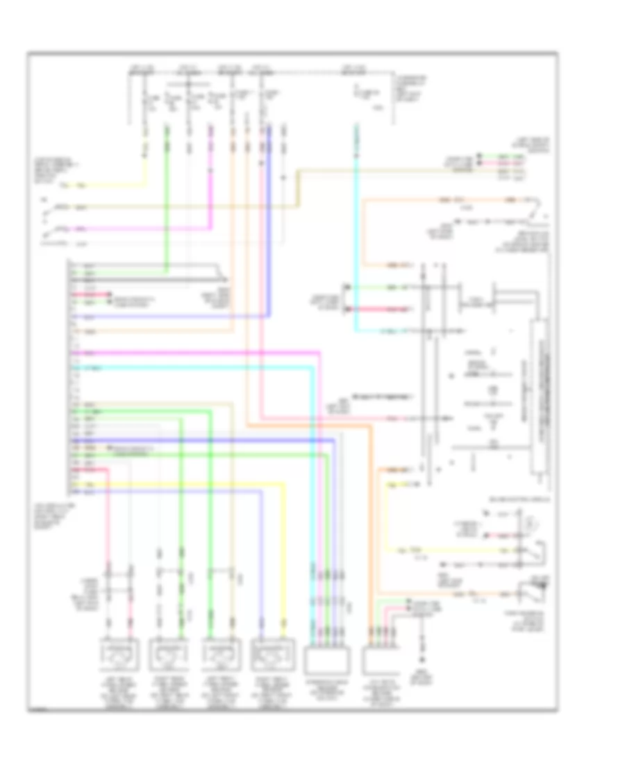
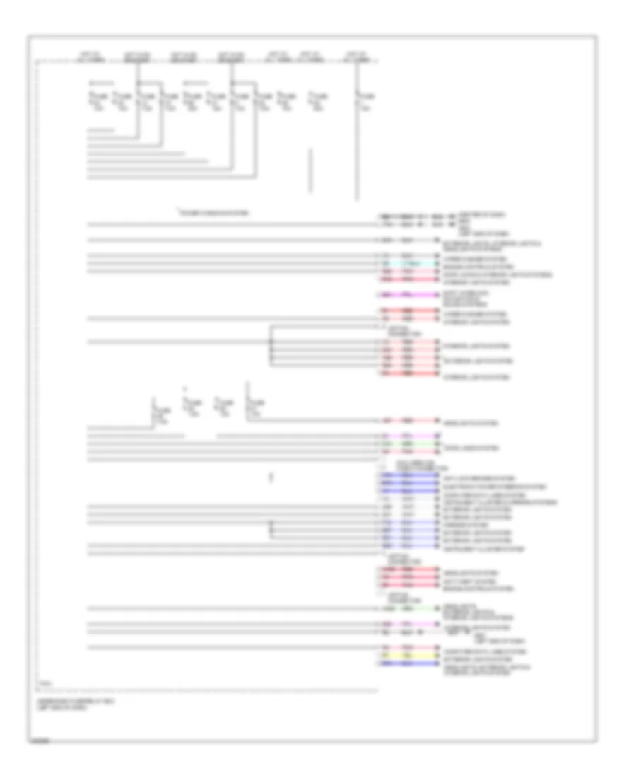
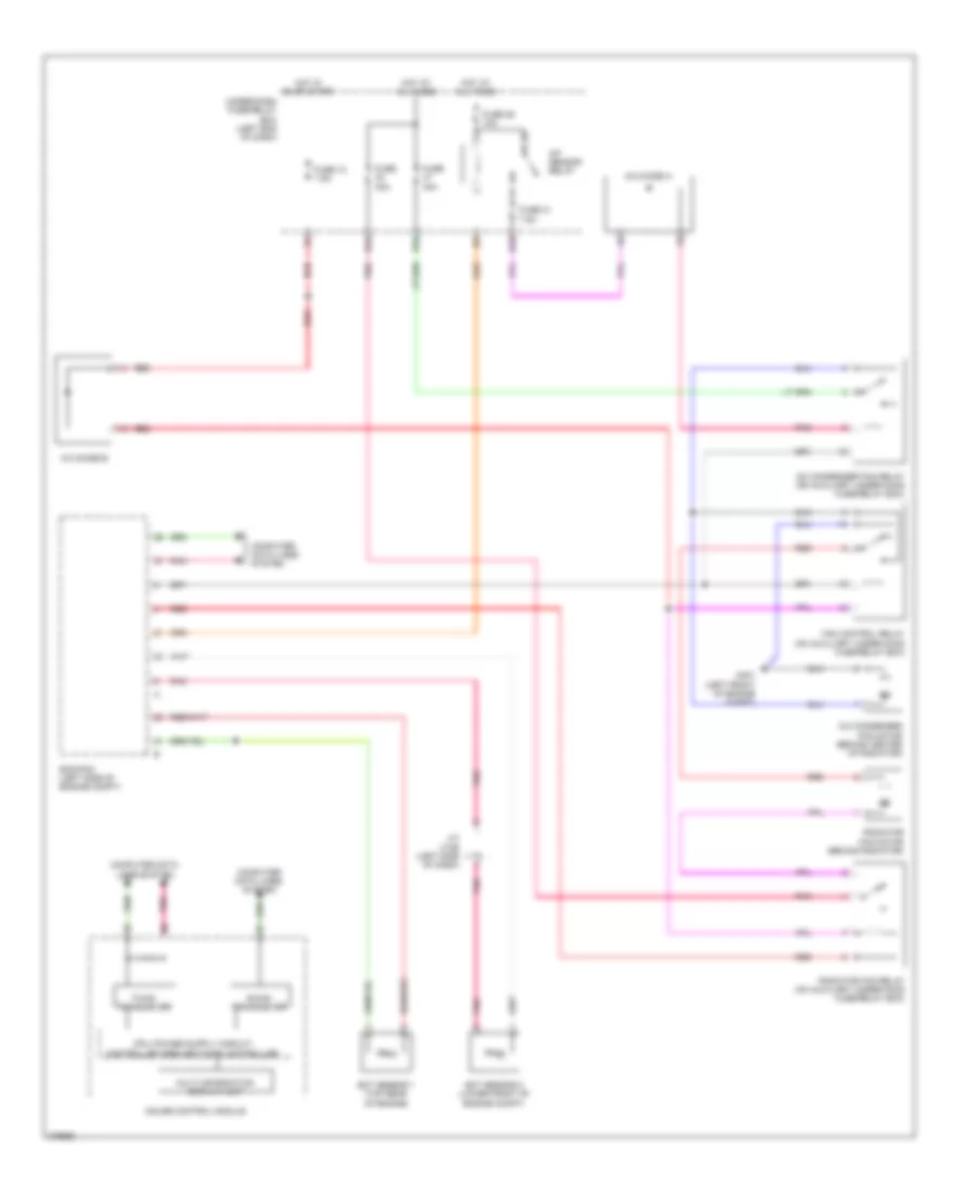
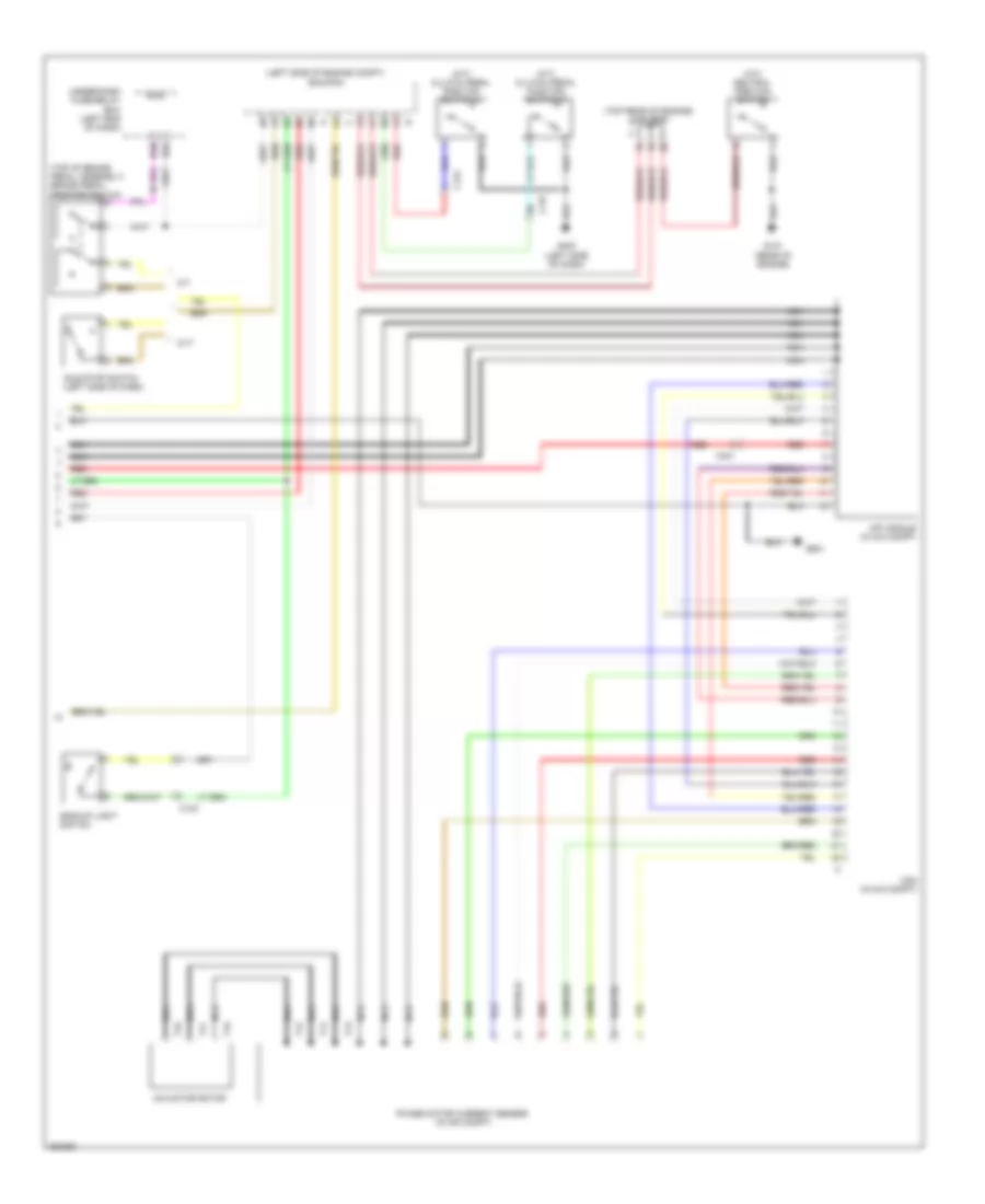
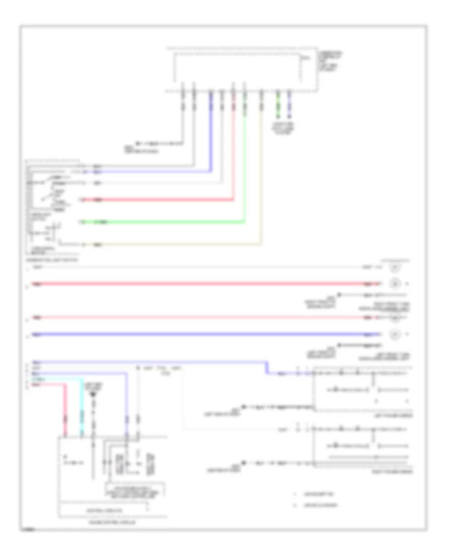
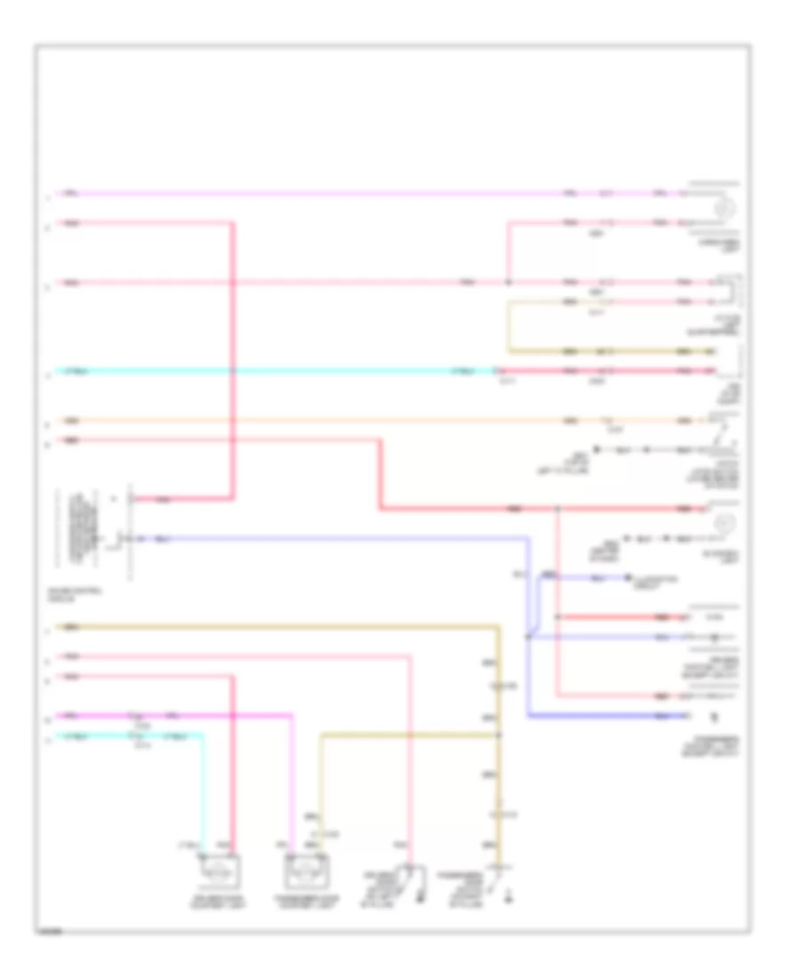
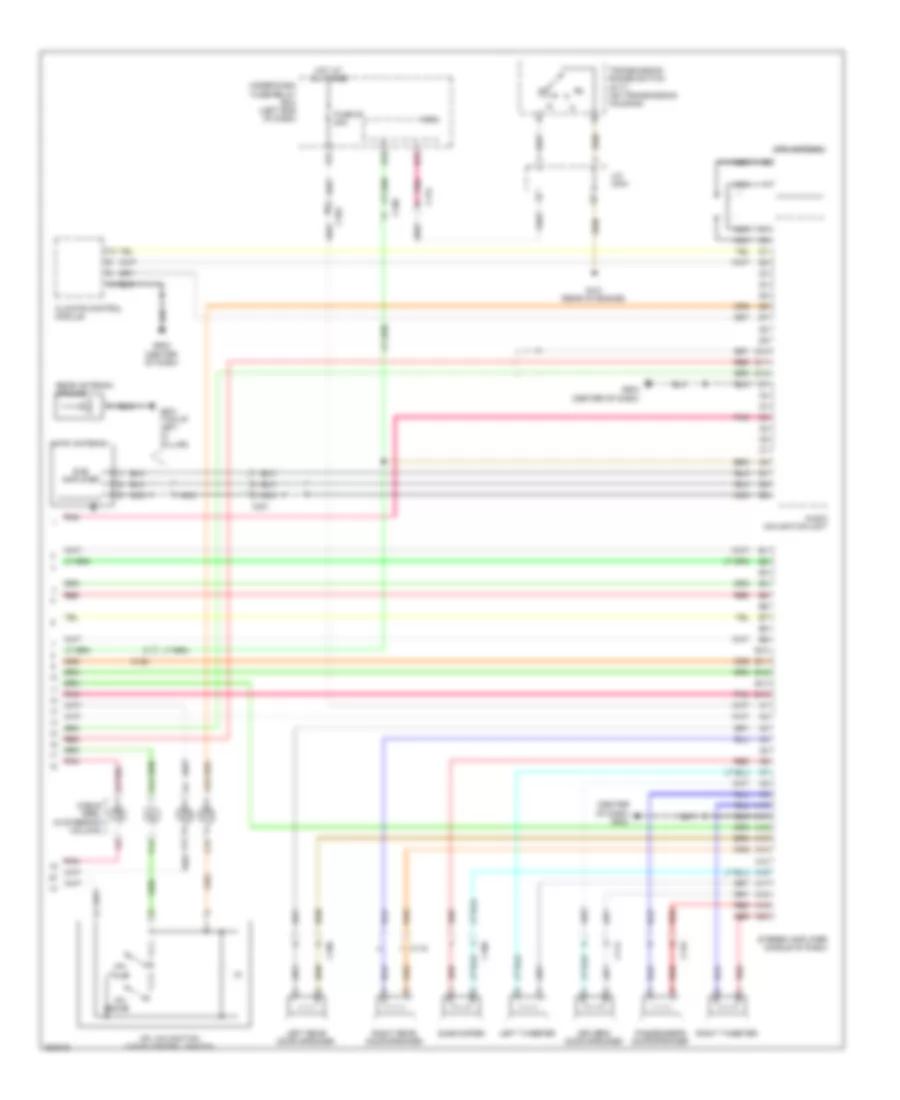
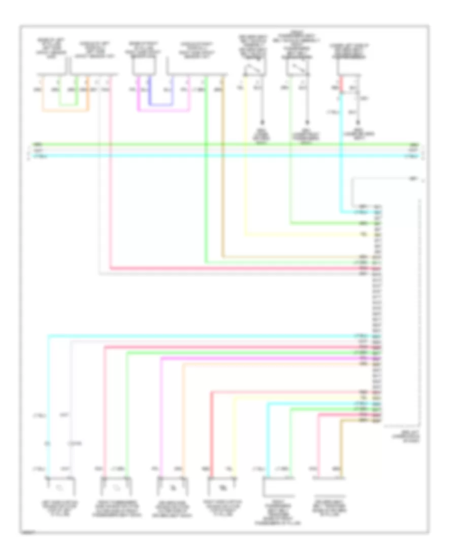
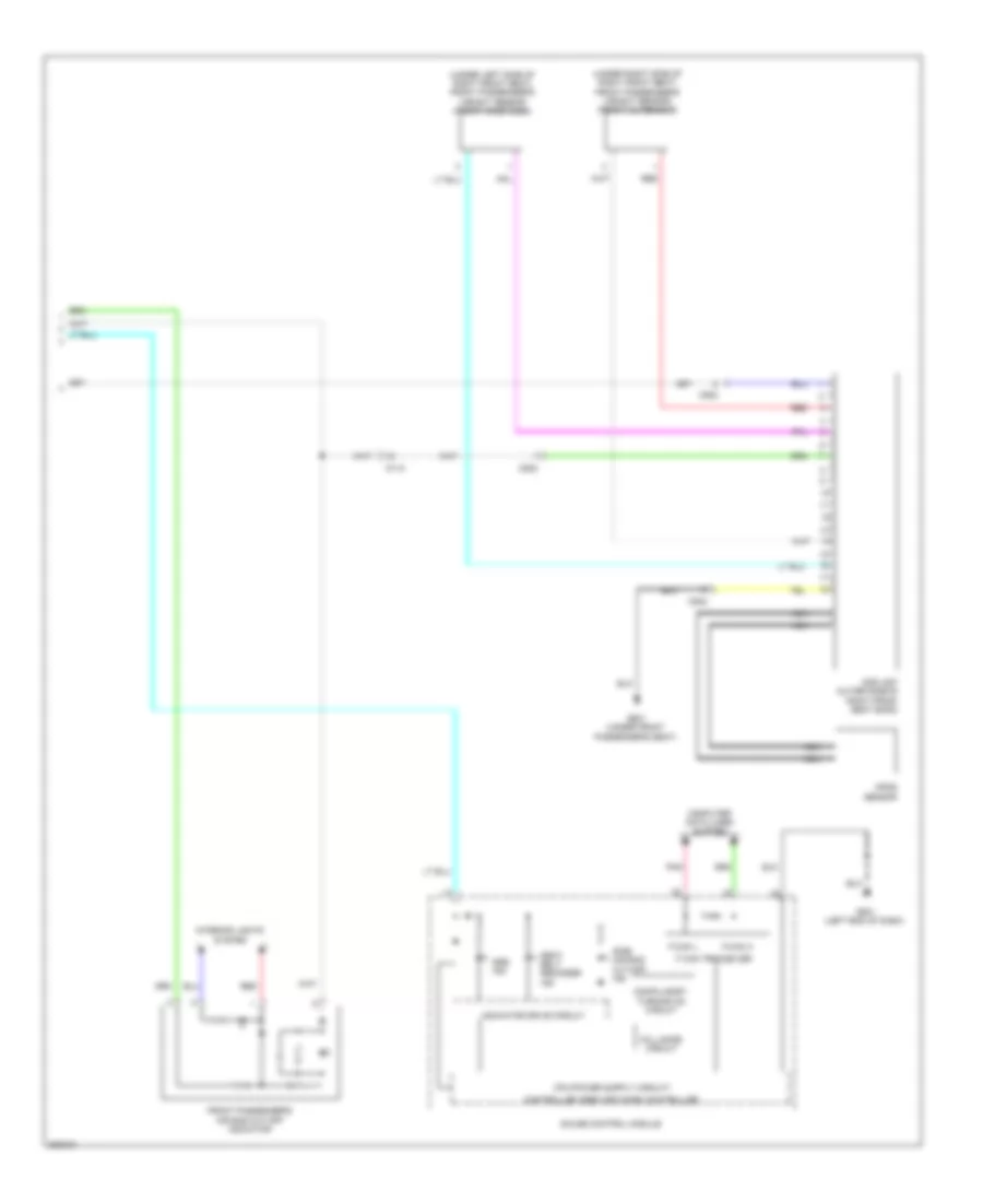
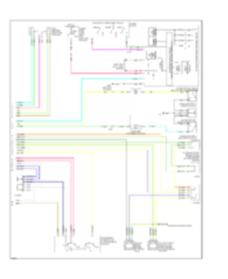
Automatic A/C Wiring Diagram (2 of 2) for Honda CR-Z EX 2012
List of elements for Automatic A/C Wiring Diagram (2 of 2) for Honda CR-Z EX 2012:
- (behind center of radiator) a/c condenser fan motor
- (behind radiator) radiator fan motor
- (left side of engine compt) ecm/pcm
- (lower front of engine compt) ect sensor 2
- (on auxiliary under-hood fuse/relay box) a/c condenser fan relay
- (on auxiliary under-hood fuse/relay box) fan control relay
- (on auxiliary under-hood fuse/relay box) radiator fan relay
- 10 v stabilizing circuit
- 3 mode switch
- A/c compressor clutch relay (on auxiliary under-hood fuse/relay box)
- A/c pressure sensor (right front of engine compt)
- B-can transceiver
- Blower motor (under right side of dash)
- C103
- C113
- C117
- C118
- Computer data lines system
- Dimming circuit
- Eco ind
- Econ switch
- Ect sensor 1 (top rear of engine)
- F-can transceiver
- G401 (left front of engine compt)
- G501 (left end of dash)
- G502 (center of dash)
- Gauge control module
- Humidity sensor
- Humidity/in-car temperature sensor (right of steering column)
- In-car temperature sensor
- Indicator drive circuit
- J/c c126
- Multi-information display unit
- Normal mode ind
- Normal switch
- Outside air temperature sensor (behind right side of front bumper)
- Pnk
- Power transistor (left side of hvac unit)
- Red
- Sport mode ind
- Sport switch
ANTI-LOCK BRAKES
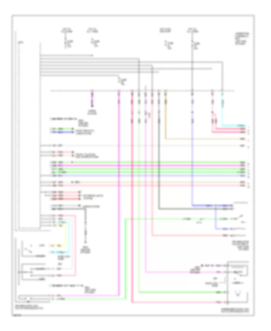
Anti-lock Brakes Wiring Diagram for Honda CR-Z EX 2012
List of elements for Anti-lock Brakes Wiring Diagram for Honda CR-Z EX 2012:
- (left side of engine compt) ecm/pcm
- (top of brake pedal assembly) brake pedal position switch
- A10
- A13
- A14
- A18
- A32
- A35
- A36
- A37
- A40
- Abs ind
- Area network controller
- B12
- B26
- B30
- Brake fluid level switch (on brake master cylinder reservoir)
- Brake system ind
- C102
- C103
- C115
- C118
- C122
- Computer data lines system
- F-can transceiver
- Fuse 1 15a
- Fuse 10a
- Fuse 11 7.5a
- Fuse 22 7.5a
- Fuse 30a
- G202 (right side of engine compt)
- G403 (left side of dash)
- G501 (left end of dash)
- G502 (center of dash)
- Gauge control module
- Hot at all times
- Hot in on or start
- Indicator drive circuit
- Interior lights system
- Left front wheel speed sensor (on left front wheel hub assembly)
- Left rear wheel speed sensor (on left rear wheel hub assembly)
- Micu
- Parking brake switch (at base of park lever)
- Pnk
- Red
- Right front wheel speed sensor (on right front wheel hub assembly)
- Right rear wheel speed sensor (on right rear wheel hub assembly)
- Steering angle sensor (on steering column)
- Under- dash fuse/ relay box (left end of dash)
- Under-dash fuse/relay box (left end of dash)
- Vsa ind
- Vsa modulator- control unit (right rear of engine compt)
- Vsa off ind
- Vsa off switch
- Yaw rate acceleration sensor (under middle of dash)
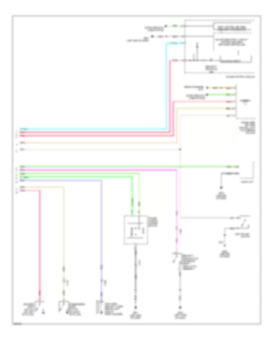
ANTI-THEFT
Forced Entry Wiring Diagram (1 of 2) for Honda CR-Z EX 2012
List of elements for Forced Entry Wiring Diagram (1 of 2) for Honda CR-Z EX 2012:
- A20
- A22
- A28
- Aa6
- B28
- B30
- C114
- C123
- Computer data
- D17
- D26
- D27
- D40
- Door lock knob
- Driver's door lock actuator/knob switch
- Driver's door unlock relay (left side of dash)
- Exterior lights system
- F10
- F11
- Fuse 10a
- Fuse 15a
- Fuse 20a
- G501 (left end of dash)
- G502 (center of dash)
- Horns system
- Hot at all times
- Hot in on or start
- Key
- Lines system
- Lock
- Micu
- N10
- Passenger's door lock actuator/knob switch
- Pnk
- Q18
- Q28
- Q29
- Red
- Trunk, tailgate, fuel doors system
- Under-dash fuse/relay box (left end of dash)
- Unlock
- Y14
Forced Entry Wiring Diagram (2 of 2) for Honda CR-Z EX 2012
List of elements for Forced Entry Wiring Diagram (2 of 2) for Honda CR-Z EX 2012:
- (rear of engine) g101
- A12
- Antenna
- Audio unit
- Blinking circuit
- Body controller area network transceiver
- C102
- C114
- C115
- Computer data lines system
- Driver's door switch (on left "b" pillar)
- G403 (left side of dash)
- G501 (left end of dash)
- G502 (center of dash)
- G503 (center of dash)
- Gauge control module
- High horn/ security horn (behind left side of front bumper)
- Ignition key switch
- Immobilizer- keyless control unit (in steering column)
- Lock
- Passenger's door switch (on right "b" pillar)
- Pnk
- Power window master switch
- Security hood switch (on engine compt hood latch assembly)
- Security indicator led
- Unlock
Immobilizer Wiring Diagram for Honda CR-Z EX 2012
List of elements for Immobilizer Wiring Diagram for Honda CR-Z EX 2012:
- (rear of engine) g101
- A36
- A37
- A43
- A44
- Antenna
- B22
- B36
- Body controller area network transceiver
- C115
- Compulsory turning off circuit
- Compulsory turning on circuit
- Computer data
- Computer data lines system
- Ecm/pcm (left side of engine compt)
- F-can h
- F-can l
- Fuel safe circuit
- Fuse 10a
- Fuse 15a
- Fuse 7.5a
- G101 (rear of engine)
- G501 (left end of dash)
- G502 (center of dash)
- Gauge control module
- Hot at all times
- Hot in on or start
- Ignition key switch
- Immobilizer system indicator
- Immobilizer- keyless control unit (in steering column)
- Indicator drive circuit
- Key
- Lines system
- Micu
- Parking brake switch (at base of park lever)
- Pgm-fi main relay 1
- Pnk
- Q18
- Tranceiver
- Under-dash fuse/relay box (left end of dash)
BODY CONTROL MODULES
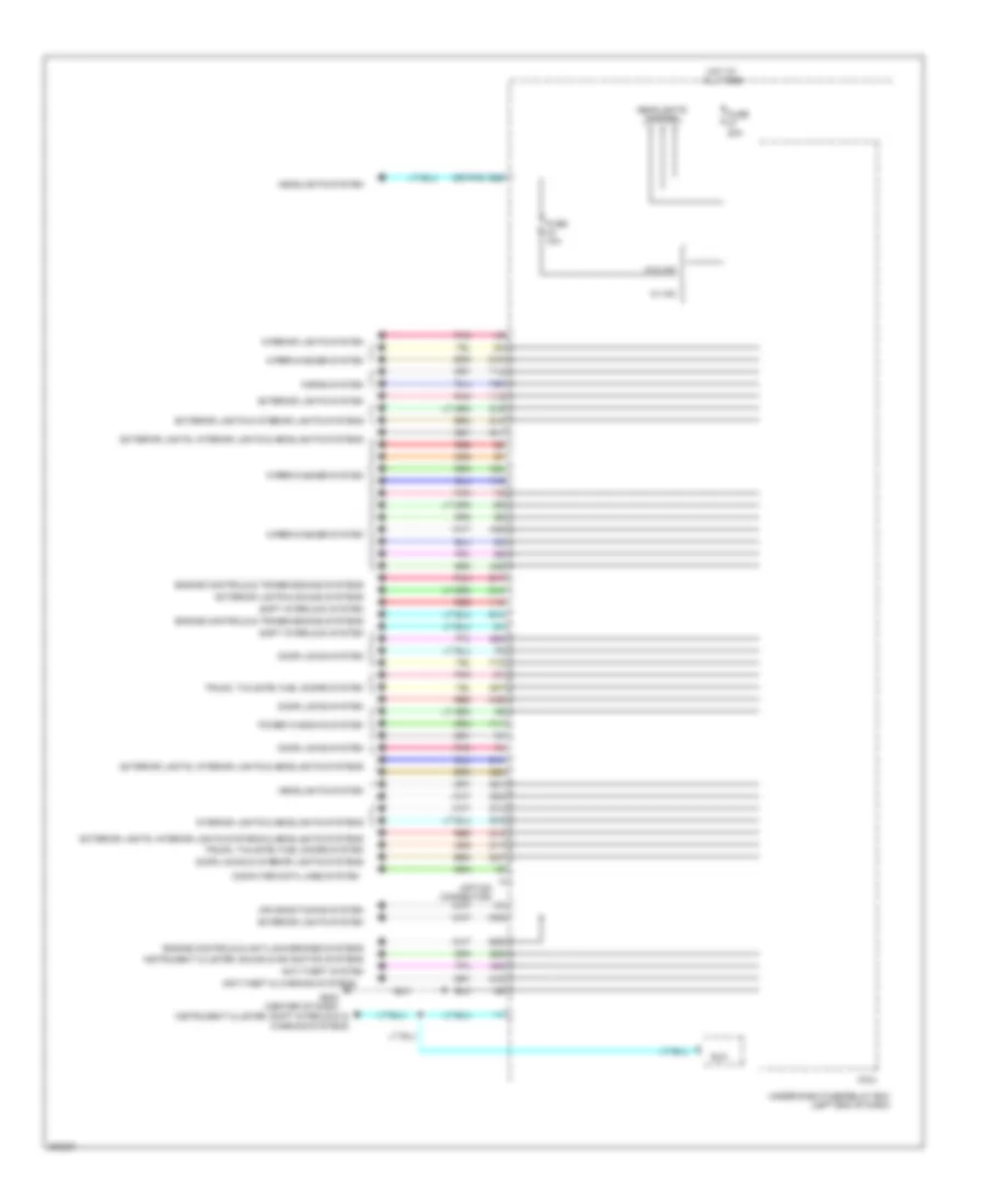
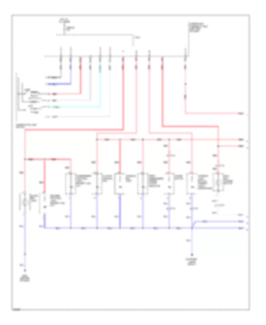
Body Control Modules Wiring Diagram (1 of 2) for Honda CR-Z EX 2012
List of elements for Body Control Modules Wiring Diagram (1 of 2) for Honda CR-Z EX 2012:
- (center of dash) g502
- (micu service check connector)
- (option connector)
- A18
- A22
- A27
- A29
- Aa24
- Aa25
- Anti-lock brakes system
- Anti-theft system
- B16
- B27
- B28
- Computer data lines system
- D26
- D29
- D31
- D40
- D41
- D42
- Door locks & interior lights systems
- Door locks system
- Electronic power steering system
- Engine controls system
- Exterior lights system
- Exterior lights, interior lights & headlights systems
- F12
- Fuse 10a
- Fuse 15a
- Fuse 20a
- Fuse 30a
- Fuse 7.5a
- G501 (left end of dash)
- Headlights system
- Headlights, exterior lights & interior lights system
- Headlights, exterior lights & interior lights systems
- Hot at all times
- Hot in on or start
- Instrument cluster & mirrors systems
- Instrument cluster system
- Interior lights system
- Micu
- Mirrors system
- N10
- Pnk
- Power windows system
- Q10
- Q19
- Q32
- Q34
- Red
- Shift interlock, navigation & sound systems
- Under-dash fuse/relay box (left end of dash)
- Wiper/washer system
- Y16
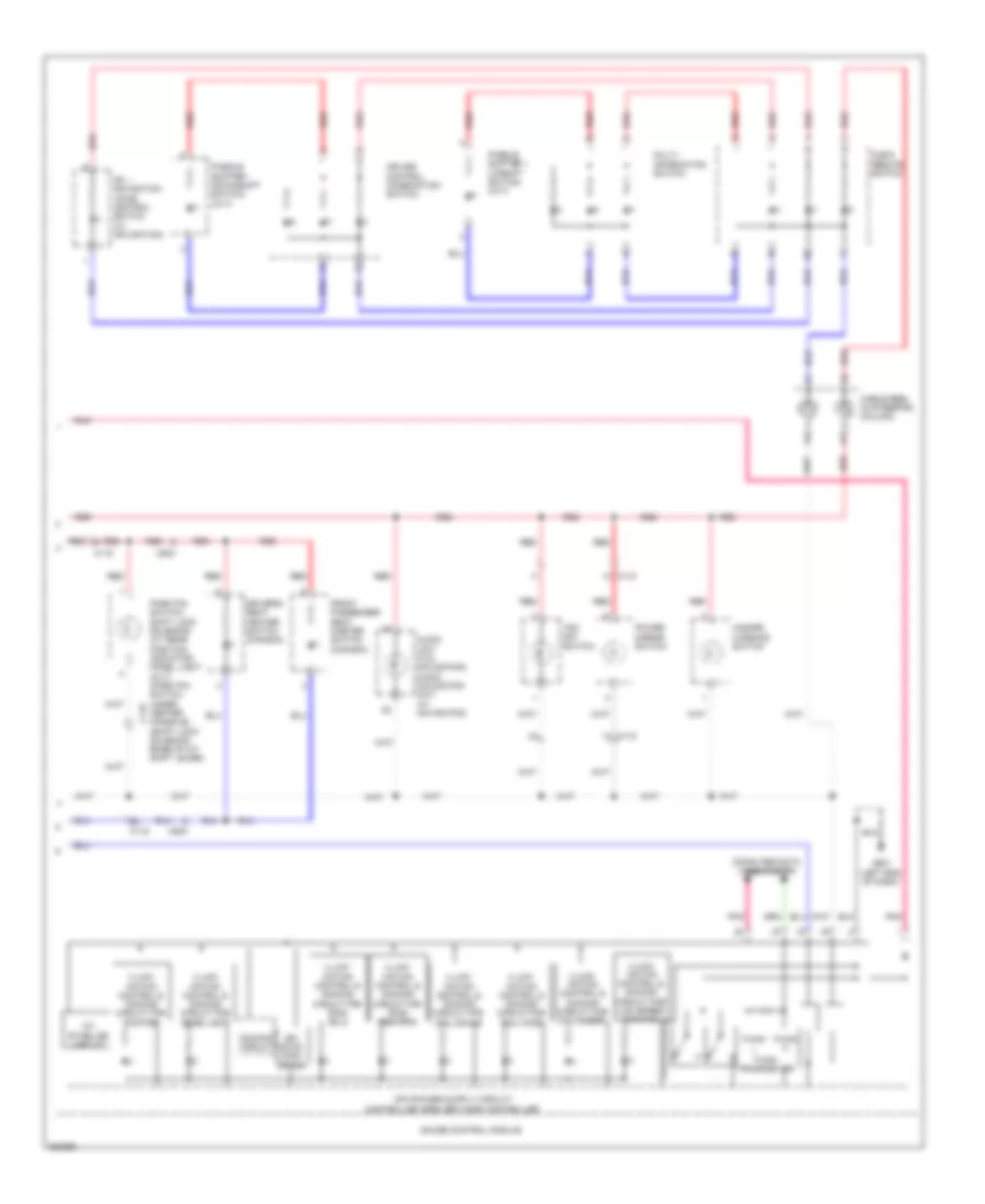
Body Control Modules Wiring Diagram (2 of 2) for Honda CR-Z EX 2012
List of elements for Body Control Modules Wiring Diagram (2 of 2) for Honda CR-Z EX 2012:
- (option connector)
- (or pnk)
- A19
- A20
- A23
- A25
- A26
- A28
- Aa6
- Air conditioning system
- Anti-theft & warning systems
- Anti-theft system
- B14
- B17
- B26
- B29
- Computer data lines system
- D10
- D17
- D18
- D27
- D30
- Door locks & interior lights systems
- Door locks system
- Eld
- Engine controls & anti-lock brakes systems
- Engine controls & transmissions systems
- Exterior lights & interior lights systems
- Exterior lights & sound systems
- Exterior lights system
- Exterior lights, interior lights & headlights systems
- Exterior lights, interior lights systems & headlights systems
- F10
- F11
- Fuse 10a
- Fuse 20a
- G502 (center of dash)
- Headlights system
- Horns system
- Hot at all times
- Instrument cluster, shift interlock & warning systems
- Instrument cluster, sound & navigation systems
- Interior lights & headlights systems
- Interior lights system
- Micu
- Pnk
- Power windows system
- Q10
- Q11
- Q12
- Q13
- Q14
- Q15
- Q16
- Q18
- Q20
- Q21
- Q22
- Q27
- Q28
- Q29
- Red
- Shift interlock system
- Trunk, tailgate, fuel doors system
- Under-dash fuse/relay box (left end of dash)
- W/ hid
- W/o hid
- Wiper/washer system
- Y12
- Y14
- Y15
COMPUTER DATA LINES
Computer Data Lines Wiring Diagram for Honda CR-Z EX 2012
List of elements for Computer Data Lines Wiring Diagram for Honda CR-Z EX 2012:
- (center of dash) g502
- (rear of engine) g101
- (right end of dash) (except usa m/t) handsfree- link control unit
- A13
- A18
- A22
- A23
- A31
- A36
- A37
- A44
- Audio unit (w/o navigation) audio-navigation unit (if equipped)
- B16
- C102
- C103
- C110
- C111
- C122
- C403
- Canada
- Climate control unit
- Data link connector (under left center of dash)
- Ecm/pcm (left side of engine compt)
- Eps control unit (left end of dash)
- Fuse 15a
- Gauge control module
- Hot at all times
- Immobilizer keyless control unit (in steering column)
- J/c c119 (left center of dash)
- J/c c120 (left center of dash)
- J/c c121 (left center of dash)
- J/c c125
- K-line
- Mcm (in ima compt)
- Micu
- Pnk
- Red
- S-net
- Srs unit (under middle of dash)
- Tpms control unit (usa) (left center of dash)
- Under-dash fuse/relay box (left end of dash)
- Usa
- Vsa modulator control unit (right rear of engine compt)
- Yaw rate- acceleration sensor (upper middle of dash)
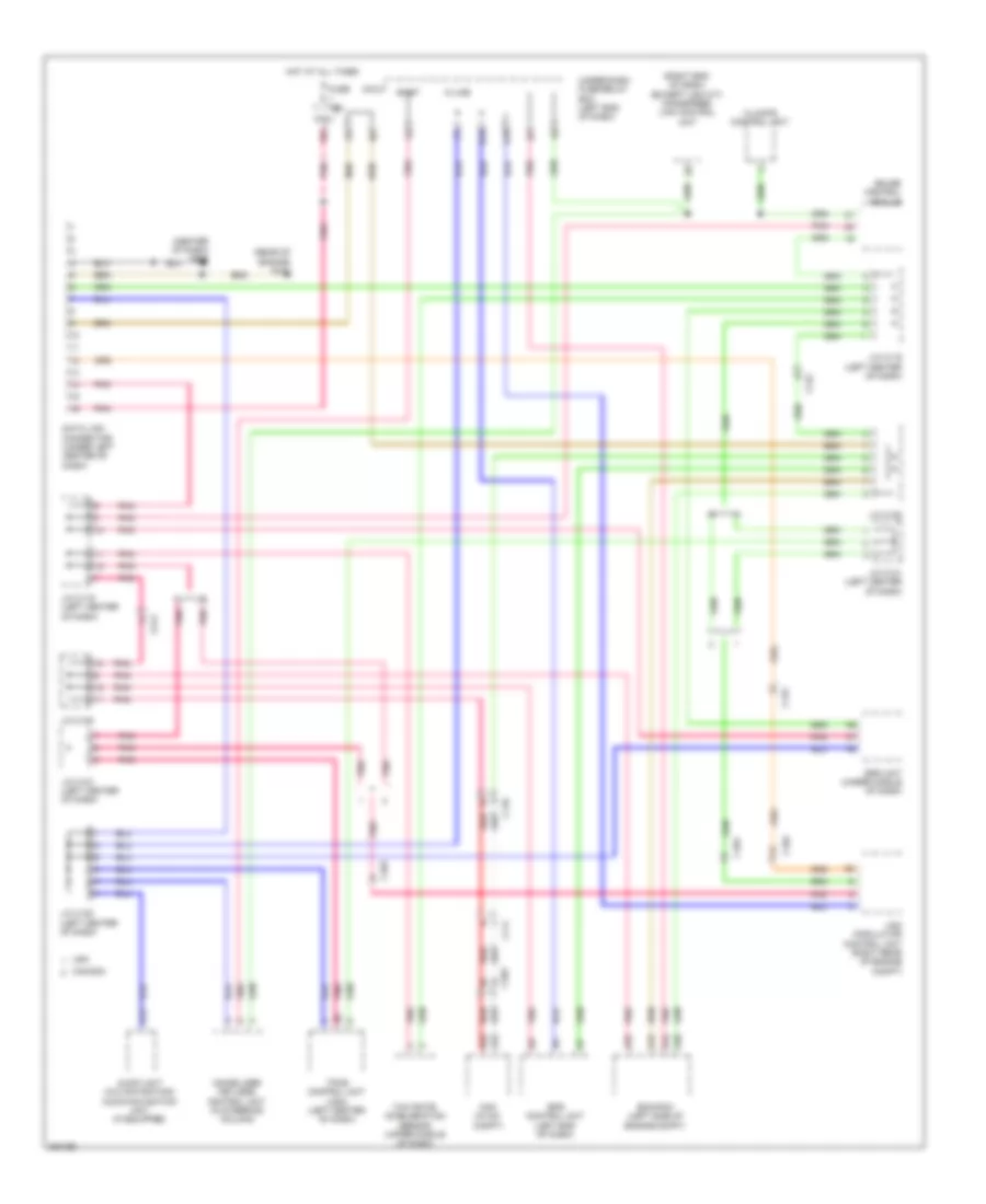
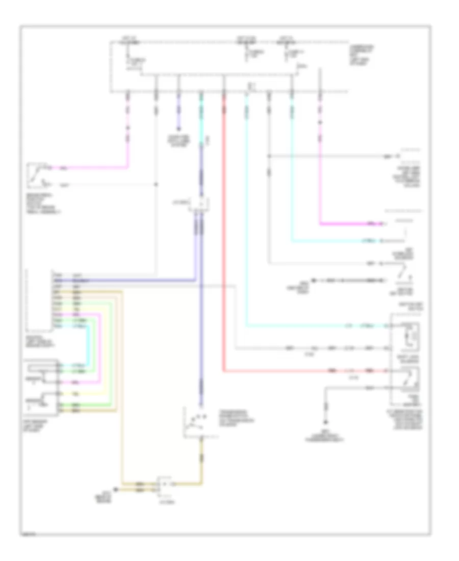
COOLING FAN
Cooling Fan Wiring Diagram for Honda CR-Z EX 2012
List of elements for Cooling Fan Wiring Diagram for Honda CR-Z EX 2012:
- A/c condenser fan motor (behind center of radiator)
- A/c condenser fan relay (on auxiliary under-hood fuse/relay box)
- A/c diode a
- A/c diode b
- A/f sensor relay
- B-can transceiver
- B10
- B33
- B34
- Computer data lines system
- Ecm/pcm (left side of engine compt)
- Ect sensor 1 (top rear of engine)
- Ect sensor 2 (lower front of engine compt)
- F-can transceiver
- Fan control relay (on auxiliary under-hood fuse/relay box)
- Fuse 10 7.5a
- Fuse 26 10a
- Fuse 30a
- Fuse 31 7.5a
- G401 (left front of engine compt)
- Gauge control module
- Hot at all times
- Hot in on or start
- J/c c126 (left side of dash)
- Multi-information display unit
- Pnk
- Radiator fan motor (behind radiator)
- Radiator fan relay (on auxiliary under-hood fuse/relay box)
- Red
- Under-dash fuse/relay box (left end of dash)
CRUISE CONTROL
Cruise Control Wiring Diagram (1 of 2) for Honda CR-Z EX 2012
List of elements for Cruise Control Wiring Diagram (1 of 2) for Honda CR-Z EX 2012:
- (left center of dash) horn diode
- (left end
- 10a
- A13
- A17
- A18
- A20
- A24
- A25
- A34
- A35
- A36
- A37
- A40
- A41
- App sensor (left side of dash)
- App sensor 1
- App sensor 2
- B12
- B19
- B21
- B26
- B30
- B34
- B41
- Brake pedal position switch (top of brake pedal assembly)
- C12
- C122
- C13
- C20
- C21
- C39
- C40
- C43
- Clutch pedal position switch b (m/t)
- Computer data lines system
- Cvt
- Cvt output shaft (driven pulley) speed sensor (on transmission housing)
- Ecm/pcm (left side of engine compt)
- Fuse 12 10a
- Fuse 24
- G101 (rear of engine)
- G403
- Horn relay (left side of dash)
- Hot at all times
- Hot in on or start
- Idle stop switch (cvt) (left side of dash)
- J/c c203
- J/c c204
- M/t
- Micu
- Of dash)
- Pnk
- Red
- Throttle actuator
- Throttle body (top right rear of engine)
- Throttle open sensor
- Transmission range switch (on transmission housing)
- Under-dash fuse/relay box
- Vehicle speed sensor (on transaxle)
- Y14
Cruise Control Wiring Diagram (2 of 2) for Honda CR-Z EX 2012
List of elements for Cruise Control Wiring Diagram (2 of 2) for Honda CR-Z EX 2012:
- (led) control ind cruise
- (led) main ind cruise
- (left end of dash) g501
- A10
- A16
- A17
- A18
- B11
- B21
- C124
- C16
- C17
- C18
- C19
- C20
- Cable reel (in steering column)
- Can controller
- Cancel switch
- Computer data lines system
- Cpu
- Cruise
- Cruise control combination switch
- Desel/ set switch
- Dimmer circuit
- Etcs control relay
- F-can h
- F-can l
- F-can transceiver
- Fuse 39 15a
- Fuse 52 15a
- G502 (center of dash)
- Gauge control module
- Hot at all times
- Indicator drive circuit
- Pgm-fi main relay 1
- Pnk
- Red
- Res/ accel switch
- Under-dash fuse/relay box (left end of dash)
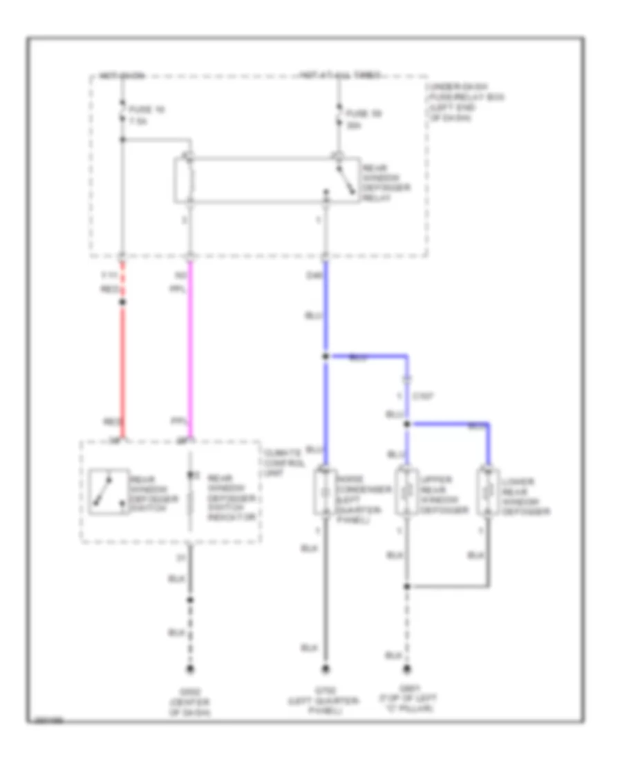
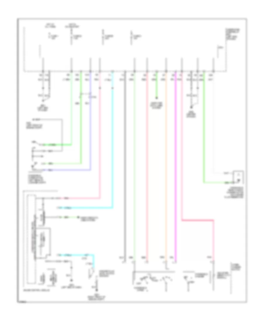
DEFOGGERS
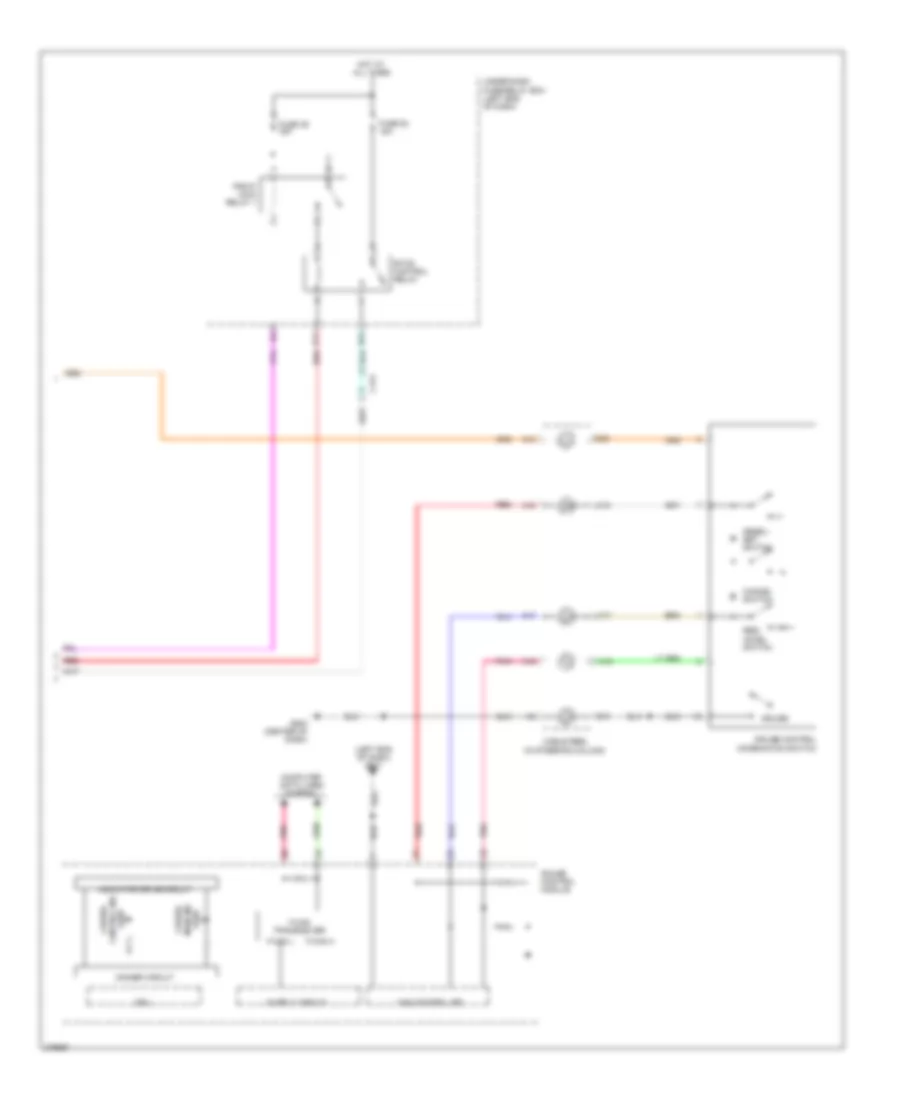
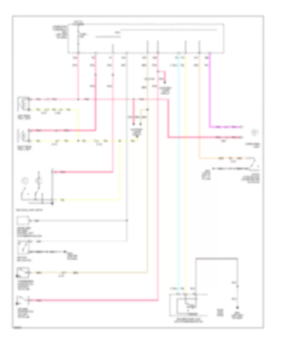
Defoggers Wiring Diagram, with Power Mirror Defogger for Honda CR-Z EX 2012
List of elements for Defoggers Wiring Diagram, with Power Mirror Defogger for Honda CR-Z EX 2012:
- 10a
- 40a
- 7.5a
- C107
- C123
- Climate control unit
- D46
- Fuse 10
- Fuse 55
- Fuse 59
- G501 (left end of dash)
- G502 (center of dash)
- G702 (left quarter- panel)
- G801 (top of left ""c" pillar)
- Hot at all times
- Hot in on
- Left power mirror (in left rearview mirror)
- Lower rear window defogger
- Noise condenser (left quater- panel)
- Q17
- Rear window defogger relay
- Rear window defogger switch/ power mirror defogger switch
- Rear window defogger switch/ power mirror defogger switch indicator
- Red
- Right power mirror (in right rearview mirror)
- Under-dash fuse/relay box (left end of dash)
- Upper rear window defogger
- Y11
Defoggers Wiring Diagram, without Power Mirror Defogger for Honda CR-Z EX 2012
List of elements for Defoggers Wiring Diagram, without Power Mirror Defogger for Honda CR-Z EX 2012:
- 30a
- 7.5a
- C107
- Climate control unit
- D46
- Fuse 10
- Fuse 59
- G502 (center of dash)
- G702 (left quarter- panel)
- G801 (top of left "c" pillar)
- Hot at all times
- Hot in on
- Lower rear window defogger
- Noise condenser (left quarter- panel)
- Rear window defogger relay
- Rear window defogger switch
- Rear window defogger switch indicator
- Red
- Under-dash fuse/relay box (left end of dash)
- Upper rear window defogger
- Y11
ELECTRONIC POWER STEERING
Electronic Power Steering Wiring Diagram for Honda CR-Z EX 2012
List of elements for Electronic Power Steering Wiring Diagram for Honda CR-Z EX 2012:
- (left kick panel) g402
- A10
- A11
- A28
- A36
- A37
- Area network controller
- B10
- B11
- B12
- B13
- B14
- B15
- B16
- Battery terminal fuse box (on battery)
- C128
- Circuit
- Compulsory turning-on circuit
- Computer data lines system
- Drive circuit indicator
- Ecm/pcm (left side of engine compt)
- Eps control unit (left end of dash)
- Eps ind
- Eps motor (left rear of engine compt)
- Eps motor angle sensor (left rear of engine compt)
- F-can h
- F-can l
- Fail-safe circuit
- Fuse 11 7.5a
- Fuse 2 70a
- Fuse 22 7.5a
- G501 (left end of dash)
- Gauge control module
- Hot at all times
- Hot in on or start
- Micu
- Nca
- Pnk
- Red
- Torque sensor (left rear of engine compt)
- Transceiver f-can
- Turning-off compulsory
- Under-dash fuse/relay box (left end of dash)
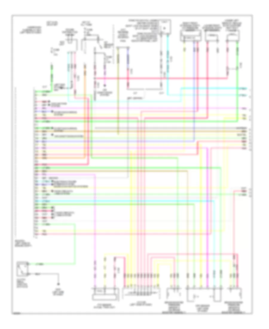
ENGINE PERFORMANCE
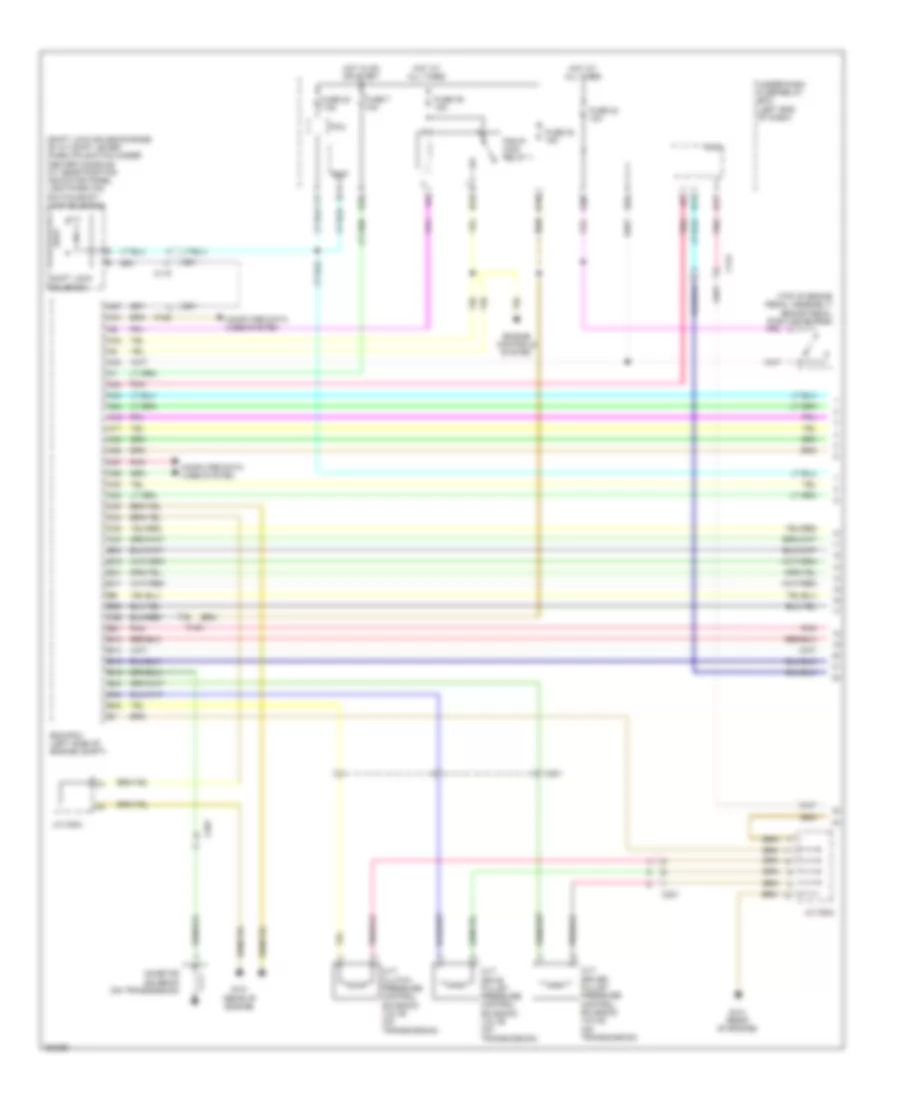
1.5L
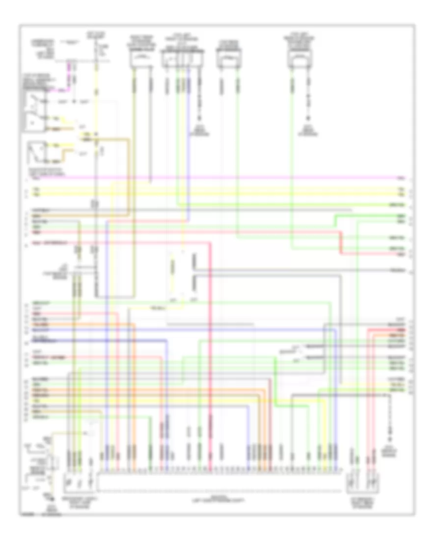
1.5L, Engine Controls Wiring Diagram (1 of 5) for Honda CR-Z EX 2012
List of elements for 1.5L, Engine Controls Wiring Diagram (1 of 5) for Honda CR-Z EX 2012:
- (left end of dash) g501
- (lower front of engine compt) ect sensor 2
- (m/t) reverse lockout solenoid
- (or pnk)
- (park pin switch: under
- (right front of engine compt) a/c pressure sensor
- (shift lock solenoid: base
- (under left rear of vehicle) evap canister vent shut valve
- A/f sensor relay
- Air conditioning system
- App sensor (left side of dash)
- B10
- B18
- B25
- Brake booster pressure sensor a (on brake booster assembly)
- Brake booster pressure sensor b (on brake booster assembly)
- C110
- C115
- C122
- C124
- Center console)
- Clutch pedal position switch b
- Computer data lines system
- Cooling fans system
- Cvt
- Ecm/pcm (left side of engine compt)
- Eld unit
- Electronic power steering system sound & navigation systems
- Ftp sensor (in fuel tank unit)
- Fuse 10a
- Fuse 7.5a
- G403 (left side of dash)
- Hot at all times
- Hot in on or start
- J/c c126 (left side of dash)
- M/t
- Of a/t shift lever) (cvt) park pin switch/ shift lock solenoid/ a/t gear position indicator panel light
- Pnk
- Power distribution system
- Red
- Starting/charging system
- Under-dash fuse/relay box (left end of dash)
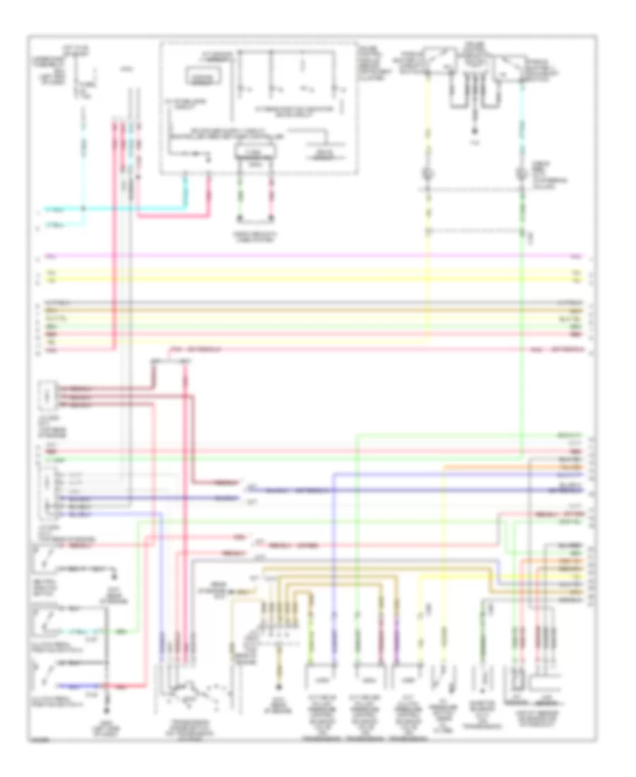
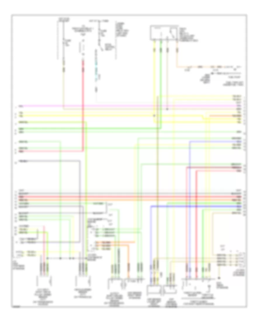
1.5L, Engine Controls Wiring Diagram (2 of 5) for Honda CR-Z EX 2012
List of elements for 1.5L, Engine Controls Wiring Diagram (2 of 5) for Honda CR-Z EX 2012:
- (or red)
- (rear of engine) g101
- 10v stabilizing circuit
- A/t dimming circuit
- A/t gear position indicator drive circuit
- B14
- B17
- C122
- C124
- C127
- C201
- Cable reel (cvt) (in steering column)
- Clutch pedal position switch a
- Clutch pedal position switch c
- Computer data lines system
- Cruise control combination switch
- Cvt
- Cvt clutch pressure control solenoid valve (on transmission)
- Cvt drive pulley pressure control solenoid valve (on transmission)
- Cvt driven pulley pressure control solenoid valve (on transmission)
- Dimming circuit
- Drive circuit
- F-can transceiver
- Fuse 7.5a
- Fwd
- G101 (rear of engine)
- G403 (left side of dash)
- Gauge control module (behind instrument cluster)
- Hot in on or start
- Iat sensor
- Inhibitor solenoid (cvt) (on transmission)
- J/c c203 (m/t) (top rear of engine)
- J/c c204 (cvt) (top rear of engine)
- M/t
- Maf sensor
- Maf/iat sensor (on engine air intake duct)
- Micu
- Neutral position switch
- Oil pressure switch (near oil filter)
- Paddle shifter (+) (upshift switch)
- Paddle shifter (-) (downshift switch)
- Pnk
- Red
- T10
- Transmission range switch (on transmission housing)
- Under-dash fuse/relay box (left end of dash)
1.5L, Engine Controls Wiring Diagram (3 of 5) for Honda CR-Z EX 2012
List of elements for 1.5L, Engine Controls Wiring Diagram (3 of 5) for Honda CR-Z EX 2012:
- (cvt)
- (or red)
- (right rear of engine) evap canister purge valve
- (top left front of engine) (cvt) egr valve & egr valve position sensor
- (top left rear of engine) rocker arm oil control solenoid
- (top of brake pedal assembly) brake pedal position switch
- (top rear of engine) ect sensor 1
- A/f sensor 1 (right rear of engine)
- B12
- B26
- B30
- C124
- Cvt
- Ecm/pcm (left side of engine compt)
- Fuse 10a
- G101 (rear of engine)
- Hot in on or start
- Idle stop switch (left side of dash)
- J/c c203 (top rear of engine)
- J/c c204 (top rear of engine)
- M/t
- Micu
- Pnk
- Red
- Secondary ho2s 2 (right side of engine)
- Under-dash fuse/relay box (left end of dash)
1.5L, Engine Controls Wiring Diagram (4 of 5) for Honda CR-Z EX 2012
List of elements for 1.5L, Engine Controls Wiring Diagram (4 of 5) for Honda CR-Z EX 2012:
- (on transmission housing)
- (top rear of engine) j/c c204
- B11
- B19
- B21
- C115
- C122
- C124
- C202
- Ckp sensor (lower left front of engine)
- Cmp sensor (top rear of engine)
- Cvt
- Cvt input shaft (drive pulley) speed sensor (cvt)
- Etcs control relay
- Fuel pump
- Fuel tank unit (inside fuel tank)
- Fuse 15a
- G101 (rear of engine)
- G602 (under driver's seat)
- Hot at all times
- Hot in on or start
- J/c c203 (top rear of engine)
- J/c c204 (top rear of engine)
- M/t
- Map sensor (right rear of engine)
- Output shaft (driven pulley) speed sensor (on transmission housing)
- Pgm-fi main relay 2 (on auxiliary under-hood fuse/relay box)
- Red
- Throttle actuator
- Throttle body (top right rear of engine)
- Throttle open sensor
- To pgm-fi main relay 1 (diagram 5 of 5)
- Under- dash fuse/ relay box (left end of dash)
- Vehicle speed sensor (cvt) (on transaxle)
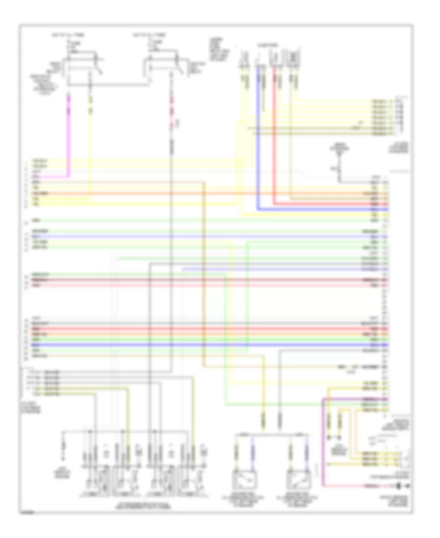
1.5L, Engine Controls Wiring Diagram (5 of 5) for Honda CR-Z EX 2012
List of elements for 1.5L, Engine Controls Wiring Diagram (5 of 5) for Honda CR-Z EX 2012:
- (rear of engine) g101
- B22
- B31
- C124
- Cvt
- Ecm/pcm (left side of engine compt)
- From etcs control relay (diagram a 4 of 5)
- Fuse 15a
- G101 (rear of engine)
- Hot at all times
- Icm
- Ignition coil relay
- Injectors
- Intake side ignition coils (above respective cylinder)
- J/c c203 (top rear of engine)
- J/c c204 (top rear of engine)
- Knock sensor (left side of engine)
- M/t
- Pgm-fi main relay 1
- Red
- Rocker arm oil pressure switch (top left rear of engine)
- Under- dash fuse/ relay box (left end of dash)
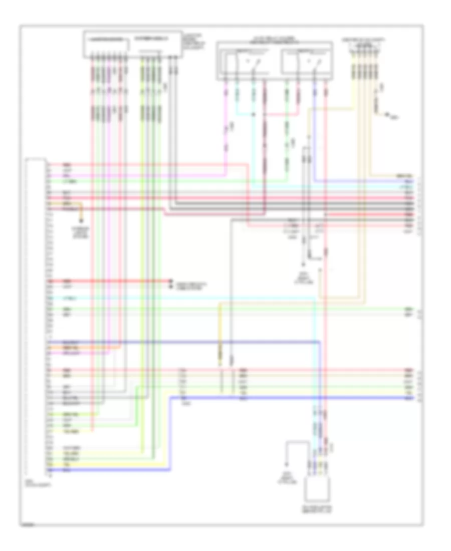
1.5L, IMA Wiring Diagram (1 of 3) for Honda CR-Z EX 2012
List of elements for 1.5L, IMA Wiring Diagram (1 of 3) for Honda CR-Z EX 2012:
- (center of ima compt) j/c c402
- (in ipu relay holder) mcm relay 1/mcm relay 2
- Battery module
- C111
- C401
- C403
- Computer data lines system
- G701 (right "c" pillar)
- G901
- Interior lights system
- Ipu module fan (behind ipu lid)
- Junction board
- Junction board (center of ima compt)
- Mcm (in ima compt)
- Nca
- Pnk
- Red
- Relay 1
- Relay 2
1.5L, IMA Wiring Diagram (2 of 3) for Honda CR-Z EX 2012
List of elements for 1.5L, IMA Wiring Diagram (2 of 3) for Honda CR-Z EX 2012:
- (in ima compt) dc-dc converter
- (left front of ima compt)
- Auto stop indicator
- B12
- C106
- C110
- C111
- C122
- C124
- C127
- C401
- C403
- Charging system indicator
- Computer data lines system
- Cvt
- D18
- D32
- D48
- Dimming circuit
- Eld unit
- F-can transceiver
- Fuse 10a
- Fuse 15a
- Fuse 7.5a
- G101 (rear of engine)
- G501 (left end of dash)
- G701 (right "c" pillar)
- G703 (left kick panel)
- Gauge control module (behind instrument cluster)
- Ground distribution system
- Hot at all times
- Hot in on or start
- Ima motor rotor position sensor (top of transmission housing)
- Ima system indicator
- Indicator drive circuit
- J/c c204 (top rear of engine)
- M/t
- Micu
- Nca
- Pnk
- Red
- T18
- Under-dash fuse/relay box (left end of dash)
- Y16
1.5L, IMA Wiring Diagram (3 of 3) for Honda CR-Z EX 2012
List of elements for 1.5L, IMA Wiring Diagram (3 of 3) for Honda CR-Z EX 2012:
- (left side of engine compt) ecm/pcm
- (m/t) clutch pedal position switch a
- (m/t) clutch pedal position switch c
- (m/t) neutral position switch
- (top of brake pedal assembly) brake pedal position switch
- (top rear of engine) j/c c203
- B26
- B30
- Backup light switch
- C124
- C127
- C401
- Cvt
- G101 (rear of engine)
- G403 (left side of dash)
- G901
- Idle stop switch (left side of dash)
- Ima motor rotor
- M/t
- Mcm (in ima compt)
- Micu
- Mpi module (in ima compt)
- Nca
- Phase motor current sensor (in ima compt)
- Red
- T12
- T13
- T14
- T15
- T16
- T17
- Under-dash fuse/relay box (left end of dash)
EXTERIOR LIGHTS
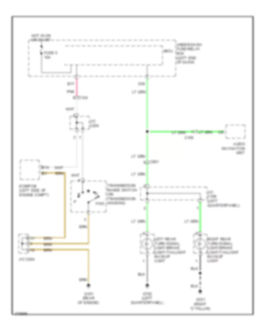
Backup Lamps Wiring Diagram, CVT for Honda CR-Z EX 2012
List of elements for Backup Lamps Wiring Diagram, CVT for Honda CR-Z EX 2012:
- Audio navigation unit
- B14
- B17
- C106
- C124
- C901
- D18
- Ecm/pcm (left side of engine compt)
- Fuse 5 10a
- G101 (rear of engine)
- G701 (right "c" pillar)
- G702 (left quarterpanel)
- Hot in on or start
- J/c c108 (left quarterpanel)
- J/c c204
- Left rear turn signal light/brake light/taillight backup light
- Micu
- Pnk
- Right rear turn signal light/brake light/taillight backup light
- Transmission range switch (on transmission housing) fwd
- Under-dash fuse/relay box (left end of dash)
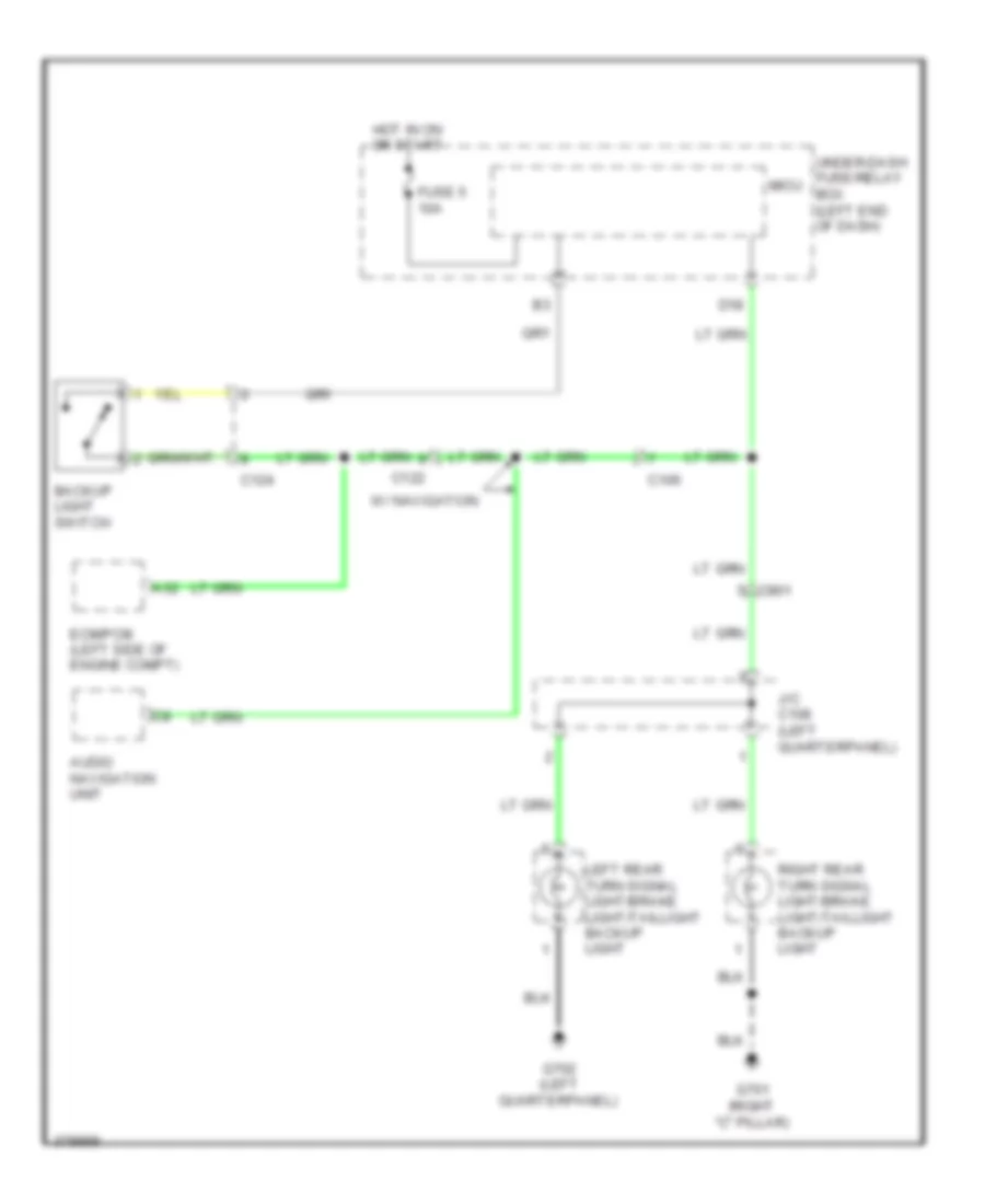
Backup Lamps Wiring Diagram, M/T for Honda CR-Z EX 2012
List of elements for Backup Lamps Wiring Diagram, M/T for Honda CR-Z EX 2012:
- A32
- Audio navigation unit
- Backup light switch
- C106
- C122
- C124
- C901
- D18
- Ecm/pcm (left side of engine compt)
- Fuse 5 10a
- G701 (right "c" pillar)
- G702 (left quarterpanel)
- Hot in on or start
- J/c c108 (left quarterpanel)
- Left rear turn signal light/brake light/taillight backup light
- Micu
- Right rear turn signal light/brake light/taillight backup light
- Under-dash fuse/relay box (left end of dash)
- W/ navigation
Exterior Lamps Wiring Diagram (1 of 2) for Honda CR-Z EX 2012
List of elements for Exterior Lamps Wiring Diagram (1 of 2) for Honda CR-Z EX 2012:
- A22
- A29
- A40
- B26
- B27
- B28
- B30
- Backup lamps circuit
- Brake pedal position switch (top of brake pedal assembly)
- C107
- C109
- C901
- D30
- D31
- D40
- D41
- Ecm/pcm (left side of engine compt)
- F12
- Fuse 1 15a
- Fuse 22 7.5a
- Fuse 23 10a
- Fuse 24 10a
- Fuse 29 10a
- G701 (right "c" pillar)
- G702 (left quarterpanel)
- G801 (top of left "c" pillar)
- Hazard warning switch
- High mount brake light
- Hot at all times
- Hot in on or start
- Interior lights system
- J/c c108 (left quarterpanel)
- Left license plate light
- Left rear turn signal light/brake light/ taillight/backup light
- Micu
- Off
- Pnk
- Q32
- Red
- Right license plate light
- Right rear turn signal light/brake light/ taillight/backup light
- Under-dash fuse/relay box (left end of dash)
- Y12
Exterior Lamps Wiring Diagram (2 of 2) for Honda CR-Z EX 2012
List of elements for Exterior Lamps Wiring Diagram (2 of 2) for Honda CR-Z EX 2012:
- (left end of dash) g501
- C123
- Combination light switch
- Computer data lines system
- Control circuits
- G201 (right front of engine compt)
- G401 (left front of engine compt)
- G501 (left end of dash)
- G502 (center of dash)
- Gauge control module
- Head
- Headlight switch
- Left front turn signal/side marker light
- Left power mirror
- Left turn signal ind
- Micu
- Off
- Park
- Pnk
- Q10
- Q11
- Q12
- Q13
- Q16
- Q19
- Red
- Right front turn signal/side marker light
- Right power mirror
- Signal ind right turn
- Turn signal switch
- Under-dash fuse/relay box (left end of dash)
- Usa ex & canada
- Usa except ex
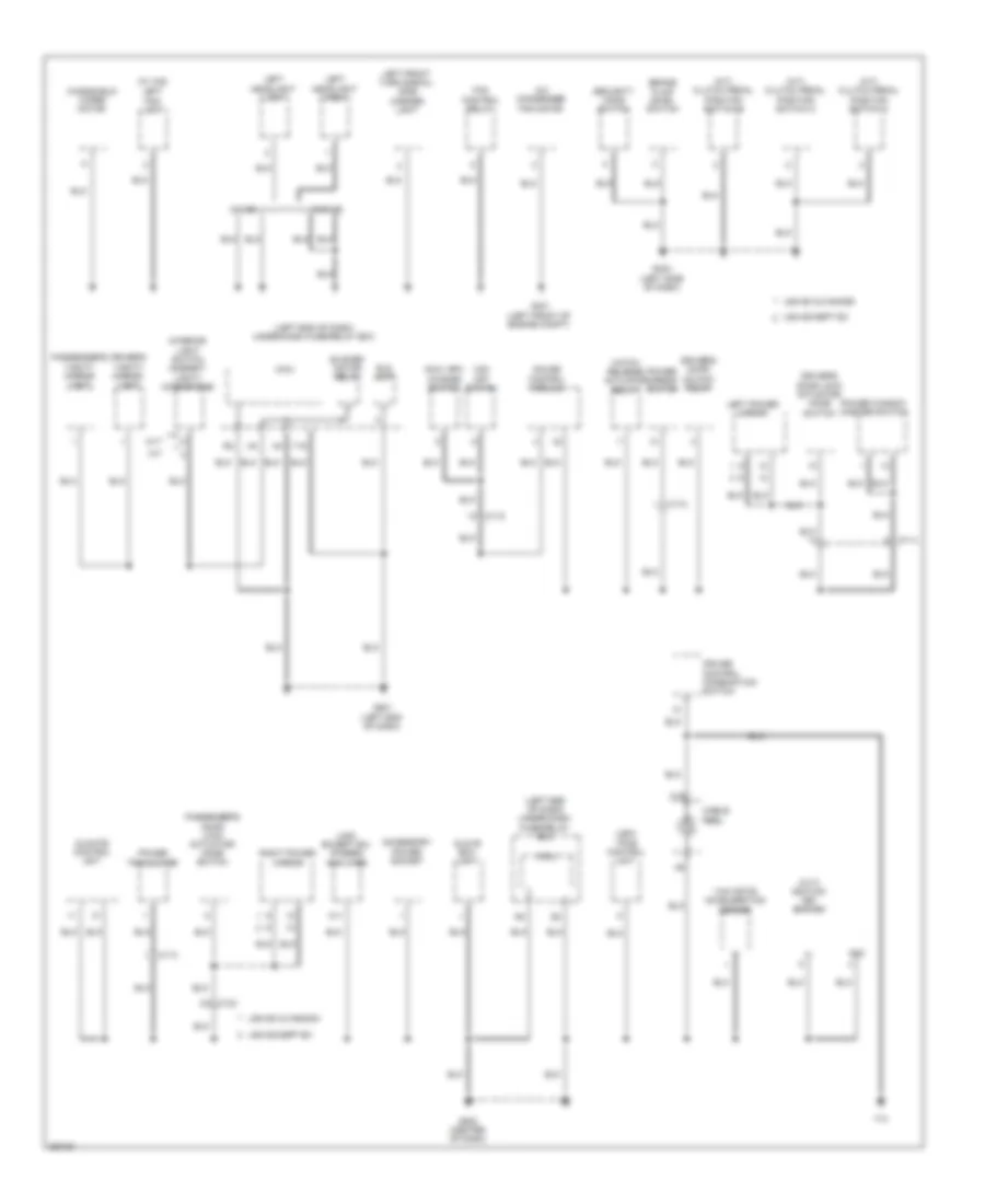
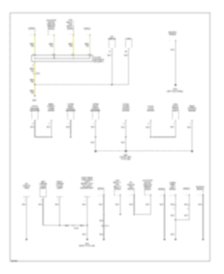
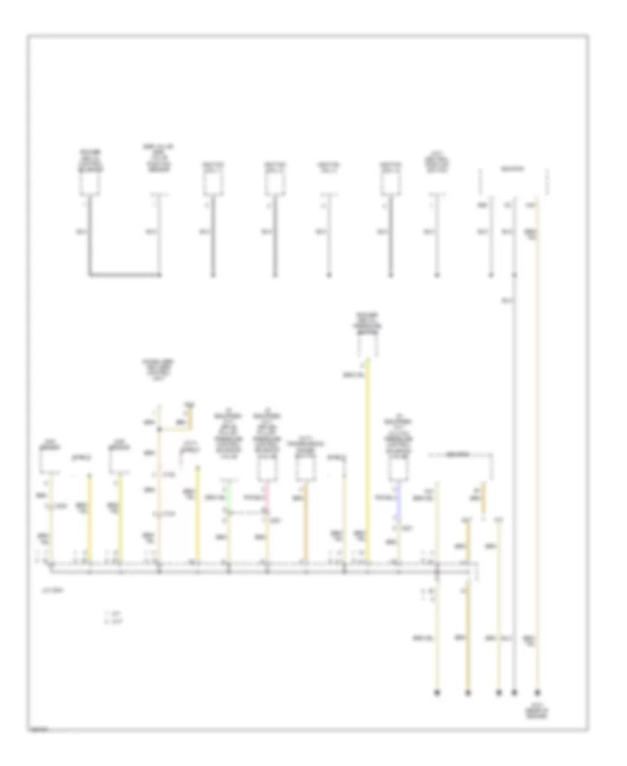
GROUND DISTRIBUTION
Ground Distribution Wiring Diagram (1 of 4) for Honda CR-Z EX 2012
List of elements for Ground Distribution Wiring Diagram (1 of 4) for Honda CR-Z EX 2012:
- (cvt) ignition key switch
- (left end of dash) under-dash fuse/relay box
- (m/t) clutch pedal position switch a
- (m/t) clutch pedal position switch b
- (m/t) clutch pedal position switch c
- (usa except ex) stereo amplifier
- (usa) tpms control unit
- (w/ hid)
- A/c condenser fan motor
- A11
- Accessory power socket
- Blower motor relay
- Brake fluid level switch
- C113
- C114
- C118
- C123
- C19
- Cable
- Climate control unit
- Cruise control combination switch
- Cvt
- Dlc
- Driver's door lock actuator/ knob switch
- Driver's door unlock relay
- Driver's vanity mirror light
- Eld unit
- Fan control relay
- G401 (left front of engine compt)
- G403 (left side of dash)
- G501 (left end of dash)
- G502 (center of dash)
- Gauge control module
- Glove box light
- Hatch release actuator relay
- Interior light switch (ambient light)/ microphone
- Km/h, mph change switch
- Left fog light
- Left front turn signal/ side marker light
- Left headlight high
- Left headlight low
- Left power mirror
- M/t
- Micu
- Passenger's door lock actuator/ knob switch
- Passenger's vanity mirror light
- Power mirror switch
- Power transistor
- Power window master switch
- Reel
- Right power mirror
- Security hood switch
- T10
- Usa ex & canada
- Usa except ex
- Vsa off switch
- W/ hid
- W/o hid
- Windshield wiper motor
- Y16
- Yaw rate acceleration sensor
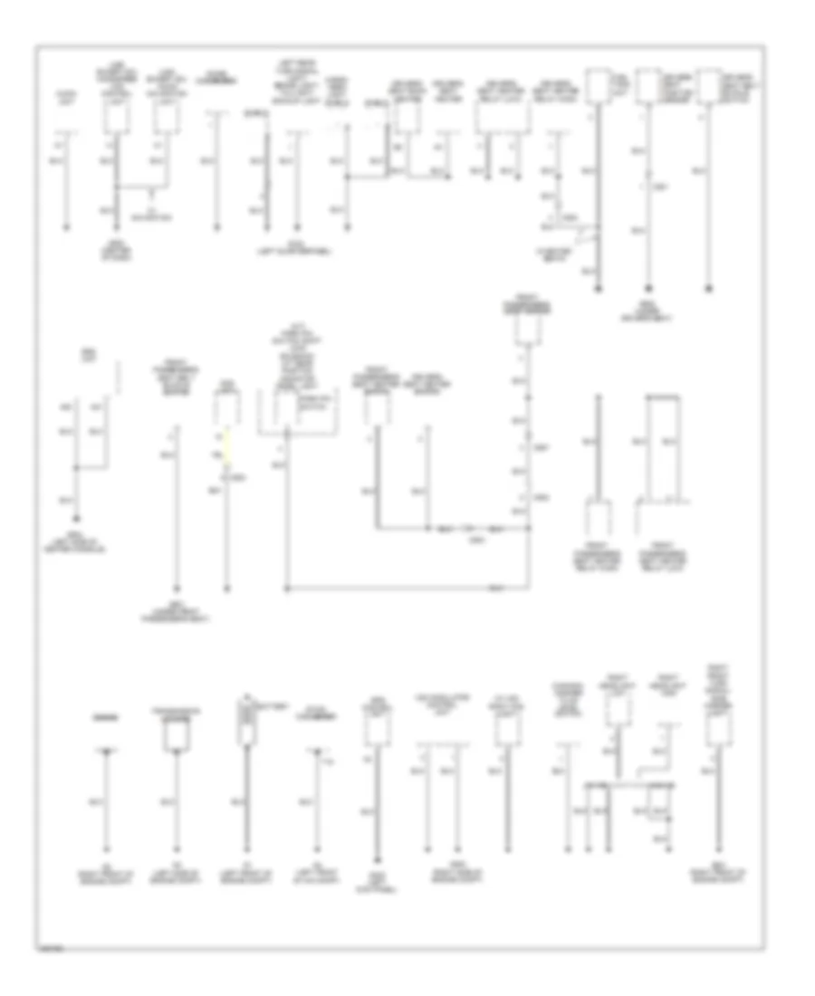
Ground Distribution Wiring Diagram (2 of 4) for Honda CR-Z EX 2012
List of elements for Ground Distribution Wiring Diagram (2 of 4) for Honda CR-Z EX 2012:
- (a/t) park pin switch/ shift lock solenoid/ a/t gear position indicator panel light
- (canada) washer fluid level switch
- (usa except ex) audio navigation unit
- (usa except ex) handsfree link control unit
- (w/ hid) right fog light
- A20
- A21
- Audio unit
- Battery
- C501
- C502
- C503
- C504
- C557
- Cargo area light shield
- Dc-dc converter
- Driver's seat back heater
- Driver's seat belt buckle switch
- Driver's seat heater
- Driver's seat heater relay (high)
- Driver's seat heater relay (low)
- Driver's seat heater switch
- Driver's seat position sensor
- Engine
- Eps control unit
- Front passenger's seat belt buckle switch
- Front passenger's seat heater
- Front passenger's seat heater relay (high)
- Front passenger's seat heater relay (low)
- Front passenger's seat heater switch
- Fuel tank unit
- G1 (left front of engine compt)
- G2 (right front of engine compt)
- G201 (right front of engine compt)
- G202 (right side of engine compt)
- G3 (left side of engine compt)
- G4 (left front of ima compt)
- G402 (left kick panel)
- G503 (center of dash)
- G504 (left side of center console)
- G601 (under front passenger's seat)
- G602 (under driver's seat)
- G702 (left quarterpanel)
- Left rear turn signal light/ brake light/ taillight/ backup light
- Noise condenser
- Ods unit
- Park pin switch
- Right front turn signal/ side marker light
- Right headlight high
- Right headlight low
- Shield
- Srs unit
- T18
- Transmission housing
- Vsa modulator control unit
- W/ hid
- W/ navigation
- W/heated seats
- W/o hid
Ground Distribution Wiring Diagram (3 of 4) for Honda CR-Z EX 2012
List of elements for Ground Distribution Wiring Diagram (3 of 4) for Honda CR-Z EX 2012:
- C109
- C111
- C401
- Cargo area light shield
- Ecm/pcm shield
- G701 (right "c" pillar)
- G703 (left kick panel)
- G801 (top of left "c" pillar)
- G901
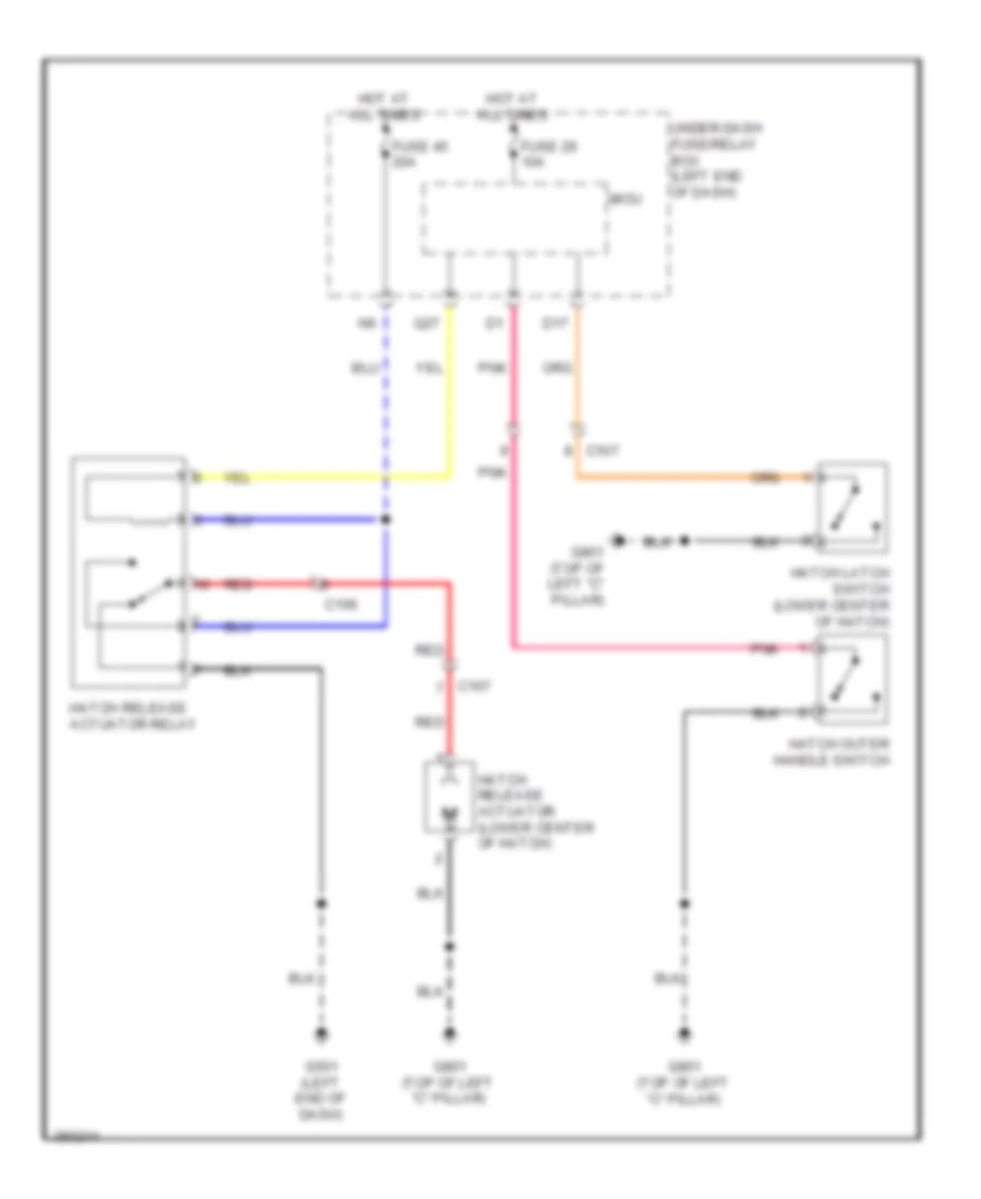
- Hatch latch switch
- Hatch outer handle switch
- Hatch release actuator
- High mount brake light
- Ima motor rotor position sensor shield
- Ipu module fan
- Ipu module fan shield
- J/c c402 (center of ima compt)
- Left license plate light
- Lower rear window defogger
- Mcm
- Mcm relay 1/ mcm relay 2 shield
- Mpi module
- Rear antenna ground
- Rear window wiper motor
- Right license plate light
- Right rear turn signal light/ brake light/ taillight/ backup light
- Shield
- Upper rear window defogger
Ground Distribution Wiring Diagram (4 of 4) for Honda CR-Z EX 2012
List of elements for Ground Distribution Wiring Diagram (4 of 4) for Honda CR-Z EX 2012:
- (cvt)
- (cvt) transmission range switch
- (if equipped) cvt clutch pressure control solenoid valve
- (if equipped) cvt drive pulley pressure control solenoid valve
- (if equipped) cvt driven pulley pressure control solenoid valve
- (m/t) neutral position switch
- B36
- C122
- C124
- C201
- C202
- C40
- C44
- Ckp sensor
- Cmp sensor
- Cvt
- Dlc
- Ecm/pcm
- Egr valve/ egr valve position sensor
- G101 (rear of engine)
- Ignition coil 1
- Ignition coil 2
- Ignition coil 3
- Ignition coil 4
- Immobilizer- keyless control unit
- J/c c204
- M/t
- Rocker arm oil control solenoid
- Rocker arm oil pressure switch
- Shield
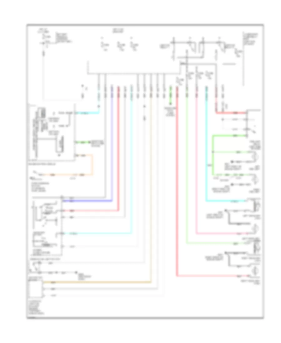
HEADLIGHTS
Headlights Wiring Diagram, with HID Headlamps for Honda CR-Z EX 2012
List of elements for Headlights Wiring Diagram, with HID Headlamps for Honda CR-Z EX 2012:
- A27
- A30
- Aa25
- Aa4
- Auto
- Automatic lighting/ sunlight sensor (top right side of dash)
- B-can transceiver
- B20
- B29
- Battery terminal fuse box (on battery)
- C102
- C104
- C115
- C122
- Canada
- Combination light switch
- Computer data lines system
- Dimmer/ flash-to-pass switch
- Dimming circuit
- Fog light relay (left side of dash)
- Fuse 100a
- Fuse 10a
- Fuse 15a
- Fuse 20a
- Fuse 7.5a
- G201 (right front of engine compt)
- G401 (left front of engine compt)
- G502 (center of dash)
- Gauge control module
- Head
- Headlight switch
- Hid unit
- High beam ind (led)
- Hot at all times
- Hot in on or start
- Ignition key switch
- Indicator drive circuit
- Left fog light
- Left headlight (high)
- Left headlight (low)
- Lighting relay 1
- Lighting relay 2
- Lights on ind (led)
- Micu
- Off
- Park
- Parking brake switch (at base of park lever)
- Pass
- Pnk
- Q10
- Q11
- Q13
- Q14
- Q15
- Q18
- Q19
- Q20
- Q21
- Q22
- Red
- Right fog light
- Right headlight (high)
- Right headlight (low)
- Under-dash fuse/relay box (left end of dash)
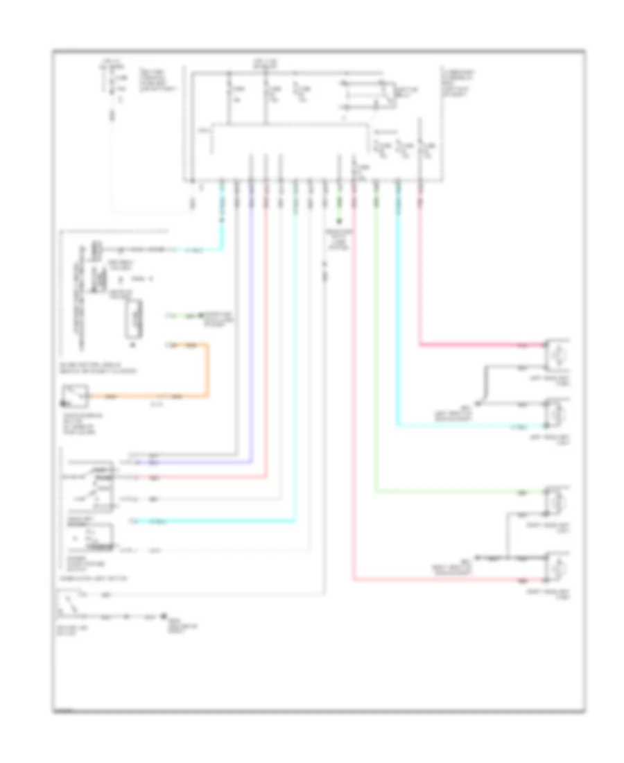
Headlights Wiring Diagram, without HID Headlamps for Honda CR-Z EX 2012
List of elements for Headlights Wiring Diagram, without HID Headlamps for Honda CR-Z EX 2012:
- (behind instrument cluster)
- A27
- A30
- B-can transceiver
- B20
- B29
- Battery terminal fuse box (on battery)
- C115
- Combination light switch
- Computer data lines system
- Dimmer/ flash-to-pass switch
- Dimming circuit
- Fuse 100a
- Fuse 10a
- Fuse 15a
- Fuse 7.5a
- G201 (right front of engine compt)
- G401 (left front of engine compt)
- G502 (center of dash)
- Gauge control module
- Head
- Headlight switch
- High beam ind (led)
- Hot at all times
- Hot in on or start
- Ignition key switch
- Indicator drive circuit
- Left headlight (high)
- Left headlight (low)
- Lighting relay
- Lights on ind (led)
- Micu
- Off
- Park
- Parking brake switch (at base of park lever)
- Passing
- Pnk
- Q10
- Q11
- Q13
- Q14
- Q15
- Q18
- Q19
- Red
- Right headlight (high)
- Right headlight (low)
- Under-dash fuse/relay box (left end of dash)
HORN
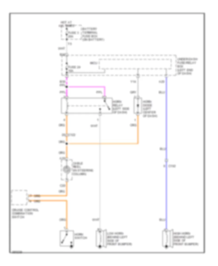
Horn Wiring Diagram for Honda CR-Z EX 2012
List of elements for Horn Wiring Diagram for Honda CR-Z EX 2012:
- A10
- A20
- B32
- Battery terminal fuse box (on battery)
- C102
- C122
- C20
- Cable reel (in steering column)
- Cruise control combination switch
- Fuse 24 10a
- Fuse 3 20a
- High horn (behind left side of front bumper)
- Horn diode (left center of dash)
- Horn relay (left side of dash)
- Horn switch
- Hot at all times
- Low horn (behind left side of front bumper)
- Micu
- Under-dash fuse/relay box (left end of dash)
- Y14
INSTRUMENT CLUSTER
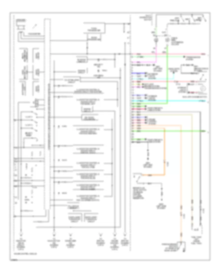
Instrument Cluster Wiring Diagram (1 of 2) for Honda CR-Z EX 2012
List of elements for Instrument Cluster Wiring Diagram (1 of 2) for Honda CR-Z EX 2012:
- 10v stabilizing circuit
- 26v dc/dc converter
- Amp
- Anti-lock brakes system transmissions system
- B-can transceiver
- Batt/assist
- Blinking circuit
- Brake fluid level switch (on brake master cylinder reservoir)
- C115
- C118
- C122
- Cable reel (in steering column)
- Circuit drive
- Compulsory turning-off circuit
- Compulsory turning-on circuit
- Computer data lines system
- Control circuit
- Cruise control system
- Dimming circuit
- Exterior lights system
- F-can transceiver
- Fall-scale circuit
- Fuel tank unit (inside fuel tank)
- Fuel/
- G403 (left side of dash)
- G501 (behind middle of dash)
- G501 (left end of dash)
- Gauge control module
- Headlights system
- High beam ind
- Illum (+)
- Illum (-)
- Illumination control & dimming circuit for dial face
- Illumination control & dimming circuit for dial scale
- Illumination control & dimming circuit for edge light
- Illumination control & dimming circuit for lcd (speed s-matic)
- Illumination control & dimming circuit for mid (amber)
- Illumination control & dimming circuit for pointer
- Information display
- Instant fuel lcd
- Interior lights system
- Km/h, mph change switch
- Lcd
- Multi-
- Multi- information switch
- Next
- Parking brake switch (at base of bake lever)
- Pnk
- Red
- Security ind
- Select/ reset
- Set/ reset
- Speaker
- Tachometer
- To cruise control ind (diagram 2 of 2)
- To eps ind (diagram 2 of 2)
- To immobilizer ind (diagram 2 of 2)
- To indicator drive circuit (diagram 2 of 2)
- To malfunction ind (diagram 2 of 2)
- Transmissions system
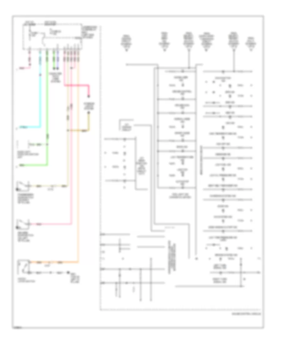
Instrument Cluster Wiring Diagram (2 of 2) for Honda CR-Z EX 2012
List of elements for Instrument Cluster Wiring Diagram (2 of 2) for Honda CR-Z EX 2012:
- A/t dimming circuit
- A/t gear position ind drive circuit (cvt)
- A12
- Abs ind
- Audio unit/ audio navigation unit
- Auto stop ind
- Brake system ind
- C106
- C107
- C115
- Charging system ind
- Computer data lines system
- Cruise control ind
- Cruise main ind
- D17
- D26
- D27
- D45
- Door ind
- Driver's door switch (on left "b" pillar)
- Econ ind
- Eps ind
- Fog light ind (canada & usa ex)
- From compulsory turning-on circuit (diagram 1 of 2)
- From dimming circuit (diagram 1 of 2)
- From high beam ind (diagram 1 of 2)
- From pin 17 (diagram 1 of 2)
- From select/ reaset switch (diagram 1 of 2)
- Fuse 1 15a
- Fuse 22 7.5a
- G801 (top of left "c" pillar)
- Gauge control module
- Hatch latch switch
- High temperature ind
- Hot at all times
- Hot in on or start
- Ima system ind
- Immobilizer ind
- Indicator drive circuit
- Interior lights system
- Left turn signal ind
- Light-on ind
- Low fuel ind
- Low oil pressure ind
- Low temperature ind
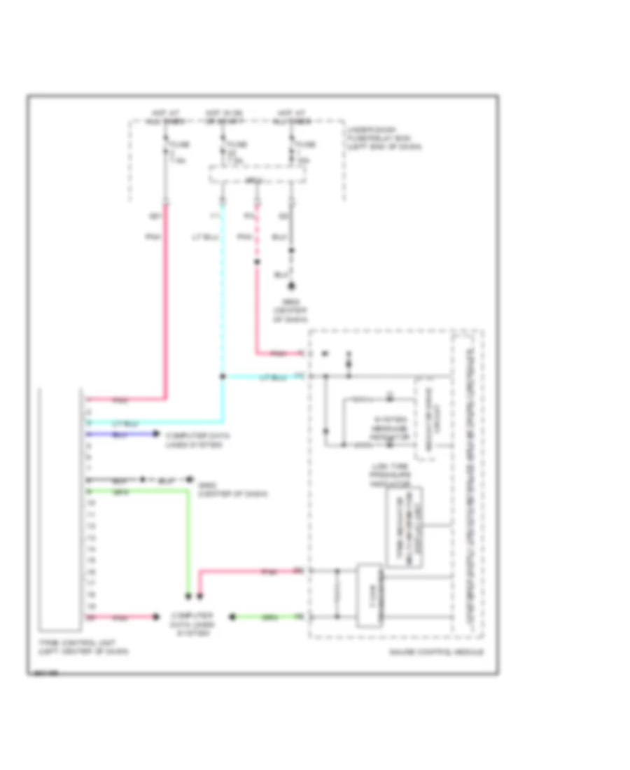
- Low tire pressure ind (usa)
- Malfunction ind
- Message ind
- Network controller controller area
- Normal mode ind
- Passenger's door switch (on right "b" pillar)
- Pnk
- Q29
- Right turn signal ind
- Seat belt reminder ind
- Side air bag cutoff ind
- Sport mode ind
- Srs ind
- Under-dash fuse/relay box (left end of dash) micu
- Vsa ind
- Vsa off ind
INTERIOR LIGHTS
Courtesy Lamps Wiring Diagram (1 of 2) for Honda CR-Z EX 2012
List of elements for Courtesy Lamps Wiring Diagram (1 of 2) for Honda CR-Z EX 2012:
- C106
- C107
- C115
- C116
- Courtesy light diode
- D17
- D26
- D27
- D29
- D42
- D45
- Driver's vanity mirror light (except usa m/t)
- Fuse 1 15a
- Fuse 7.5a
- G501 (left end of dash)
- G502 (center of dash)
- Hot at all times
- Hot in on or start
- Ignition key switch
- Immobilizer keyless control unit (in steering column)
- Individual map lights
- Interior light switch (ambient light)/microphone
- Left rear tray light
- Micu
- Passenger's vanity mirror light (except usa m/t)
- Pnk
- Q18
- Red
- Right rear tray light
- Under-dash fuse/relay box (left end of dash)
Courtesy Lamps Wiring Diagram (2 of 2) for Honda CR-Z EX 2012
List of elements for Courtesy Lamps Wiring Diagram (2 of 2) for Honda CR-Z EX 2012:
- C106
- C107
- C111
- C114
- C115
- C123
- C403
- C901
- Cargo area light
- Driver's door courtesy light
- Driver's door switch (on left "b" pillar)
- Driver's footwell light (except usa m/t)
- G502 (center of dash)
- G801 (top of left "c" pillar)
- Gauge control module
- Glove box light
- Hatch latch switch (lower center of hatch)
- Illumination circuit
- J/c c108 (left quarterpanel)
- Mcm (in ima compt)
- Passenger's door courtesy light
- Passenger's door switch (on right "b" pillar)
- Passenger's footwell light (except usa m/t)
- Pnk
- Red
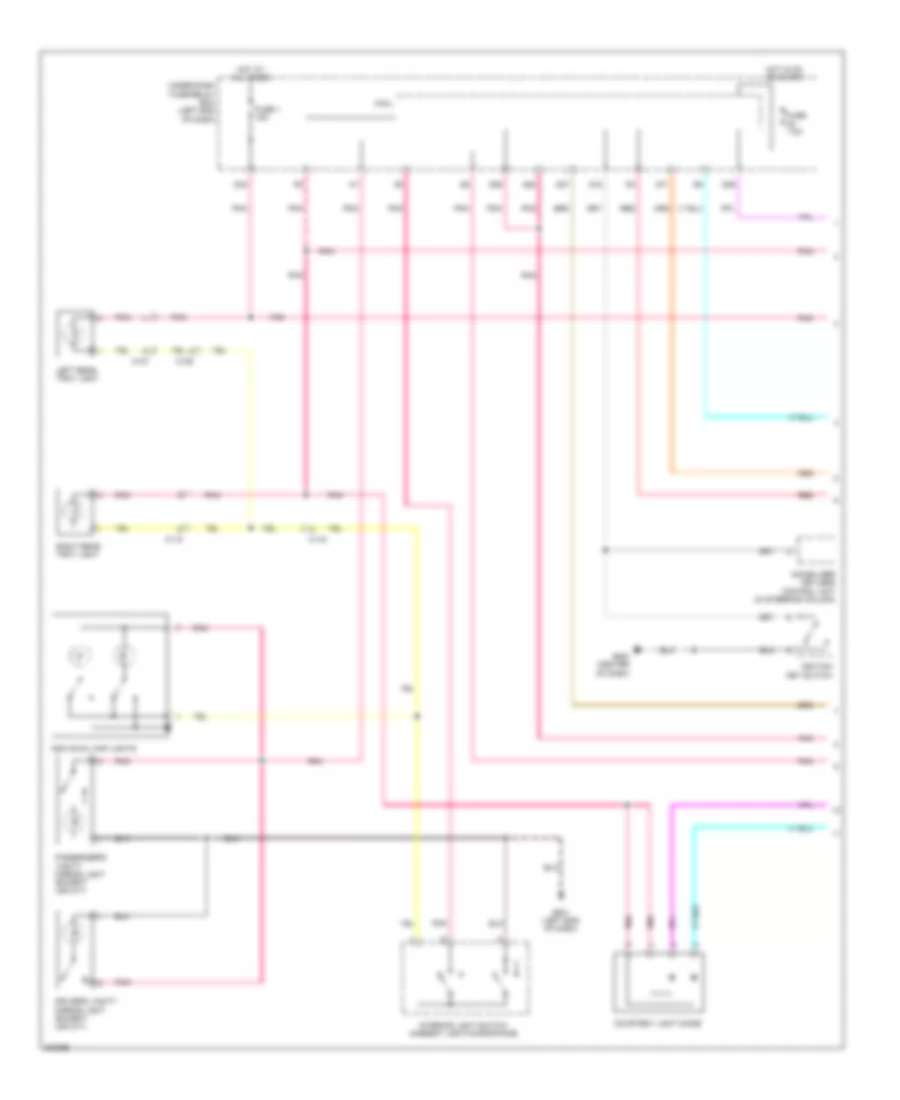
Entry Light Timer Wiring Diagram for Honda CR-Z EX 2012
List of elements for Entry Light Timer Wiring Diagram for Honda CR-Z EX 2012:
- C106
- C107
- C115
- C116
- C901
- Cargo area light
- Courtesy lamps circuit
- D17
- D26
- D27
- D29
- D42
- Door lock knob
- Driver's door lock actuator/knob switch
- Driver's door switch (on left "b" pillar)
- F10
- Fuse 1 15a
- G501 (left end of dash)
- G502 (center of dash)
- G801 (top of left "c" pillar)
- Hatch latch switch (lower center of hatch)
- Hot at all times
- Ignition key switch
- Immobilizer keyless control unit (in steering column)
- Individual map lights
- Left rear tray light
- Lock
- Micu
- Passenger's door switch (on right "b" pillar)
- Pnk
- Q18
- Right rear tray light
- Under-dash fuse/relay box (left end of dash)
- Unlock
Instrument Illumination Wiring Diagram (1 of 2) for Honda CR-Z EX 2012
List of elements for Instrument Illumination Wiring Diagram (1 of 2) for Honda CR-Z EX 2012:
- 3-mode switch
- Auto
- C116
- C118
- Climate control unit
- Combination light switch
- Console box light
- Courtesy lamps circuit
- Driver's footwell light (except usa m/t)
- Front passenger's air bag cutoff indicator
- Fuse 29 10a
- G502 (center of dash)
- Glove box light
- Head
- Hot at all times
- Interior light switch (ambient light)/ microphone
- Km/h, mph change switch
- Micu
- Off
- Park
- Pass
- Passenger's footwell light (except usa m/t)
- Pnk
- Q10
- Q11
- Q13
- Q14
- Q15
- Q19
- Red
- Under-dash fuse/relay box (left end of dash)
Instrument Illumination Wiring Diagram (2 of 2) for Honda CR-Z EX 2012
List of elements for Instrument Illumination Wiring Diagram (2 of 2) for Honda CR-Z EX 2012:
- 10v stabilize circuit
- 26v dc/oc conv- erter
- Audio remote switch
- Audio unit (w/o navigation) audio navigation unit (w/ navigation)
- C115
- C118
- C503
- Cable reel (in steering column)
- Computer data lines system
- Cruise control combination switch
- Dimming circuit
- Driver's seat heater switch (canada)
- F-can h
- F-can l
- F-can transceiver
- Front passenger seat haeter switch (canada)
- G501 (left end of dash)
- Gauge control module
- Hazard warning switch
- Hfl - navigation voice control switch (w/ navigation)
- Illumi- nation control & dimming circuit for dial face
- Illumi- nation control & dimming circuit for dial scale
- Illumi- nation control & dimming circuit for edge light
- Illumi- nation control & dimming circuit for lcd (speed s-matic)
- Illumi- nation control & dimming circuit for mid (amber)
- Illumi- nation control & dimming circuit for pointer
- Multi- information switch
- Paddle shifter + (upshift switch) (cvt)
- Paddle shifter - (downshift switch) (cvt)
- Park pin switch/ shift lock solenoid/ a/t gear position indicator panel light (cvt) (park pin switch: under center console) (shift lock solenoid: base of a/t shift lever)
- Pnk
- Power mirror switch
- Red
- Vsa off switch
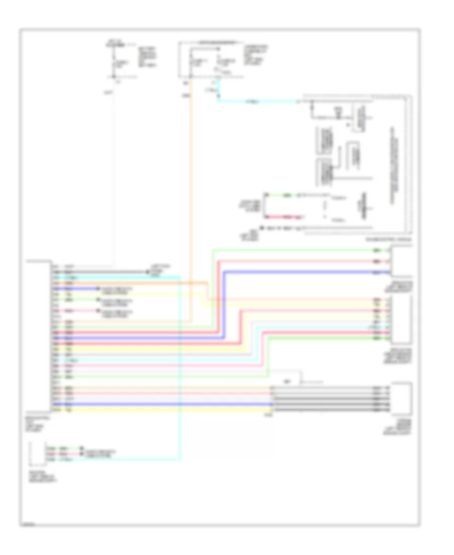
NAVIGATION
Navigation Wiring Diagram (1 of 2) for Honda CR-Z EX 2012
List of elements for Navigation Wiring Diagram (1 of 2) for Honda CR-Z EX 2012:
- (center of dash)
- (center of dash) g503
- (left end of dash)
- (m/t)
- A10
- A11
- A12
- A13
- A14
- A15
- A16
- A17
- A18
- A19
- A20
- A21
- A22
- A23
- A24
- A29
- A32
- Audio navigation unit
- Audio remote switch
- Auxiliary jack assembly
- B can transc- iever
- B10
- B11
- B12
- B13
- B14
- B15
- B16
- B17
- B18
- B19
- B20
- B21
- B22
- B23
- B24
- Backup light switch (m/t)
- C116
- C122
- C124
- Ch+
- Ch-
- Computer data lines system
- Drive circuit
- E10
- E11
- E12
- Ecm/pcm (left side of engine compt)
- Fuse 15a
- Fuse 7.5a
- G501
- G502 (center of dash)
- G503
- G503 (center of dash)
- Gauge control module
- Handsfree link control unit (right end of dash)
- Hot at all times
- Hot in acc or on
- Interior light switch (ambient light microphone)
- Micu
- Mode
- Multi information display
- Nca
- Pnk
- Q29
- Q34
- Red
- Under-dash fuse/relay box (left end of dash)
- Usb adapter control unit (lower right center of dash)
- Usb port
- Vol down
- Vol up
Navigation Wiring Diagram (2 of 2) for Honda CR-Z EX 2012
List of elements for Navigation Wiring Diagram (2 of 2) for Honda CR-Z EX 2012:
- (center of dash) g502
- A10
- A11
- A12
- A13
- A14
- A15
- A16
- A17
- A18
- A19
- A20
- A21
- Am/fm antenna
- Audio navigation unit
- B10
- B11
- B12
- B13
- B14
- B17
- C103
- C106
- C114
- C115
- C122
- C123
- C124
- C14
- C15
- C301
- Cable reel (in steering column)
- Climate control module
- D10
- D11
- D12
- D18
- Driver's door speaker
- Fuse 25 20a
- G101 (rear of engine)
- G502 (center of dash)
- G503 (center of dash)
- G801 (top of left "c" pillar)
- Gps antenna
- Hfl back
- Hfl navigation voice control switch
- Hfl talk
- Hot at all times
- J/c c204
- Left rear door speaker
- Left tweeter
- Micu
- Nca
- Passenger's door speaker
- Pnk
- Rear antenna ground
- Red
- Right rear door speaker
- Right tweeter
- Stereo amplifier (middle of dash)
- Sub amplifier
- Subwoofer
- Transmission range switch (cvt) (on transmission housing)
- Under-dash fuse/relay box (left end of dash)
POWER DISTRIBUTION
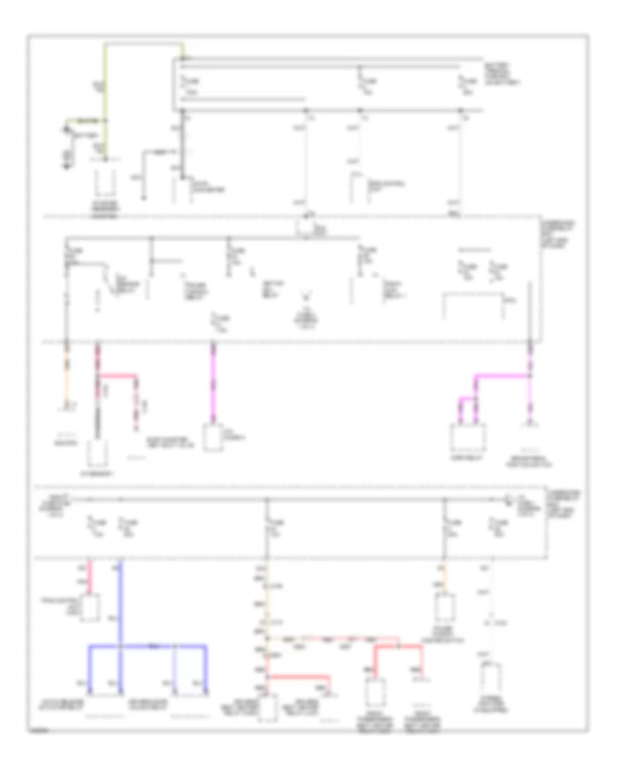
Power Distribution Wiring Diagram (1 of 4) for Honda CR-Z EX 2012
List of elements for Power Distribution Wiring Diagram (1 of 4) for Honda CR-Z EX 2012:
- (diagram 1 of 4)
- A/c diode a
- A/f sensor 1
- A/f sensor relay
- A21
- B10
- B25
- B30
- B32
- Battery
- Battery terminal fuse box (on battery)
- Brake pedal position switch
- C103
- C106
- C110
- C115
- C124
- C502
- C504
- C557
- D33
- Dc-dc converter
- Driver's door unlock relay
- Driver's seat heater relay (high)
- Driver's seat heater relay (low)
- Ecm/pcm
- Eld unit
- Eps control unit
- Evap canister vent shut valve
- From fuse 33 a
- Front passenger's seat heater relay (high)
- Front passenger's seat heater relay (low)
- Fuse 100a
- Fuse 10a
- Fuse 15a
- Fuse 20a
- Fuse 7.5a
- Fuse 70a
- Hatch release actuator relay
- Horn relay
- Ignition coil relay
- Micu
- Nca
- Pgm-fi main relay 1
- Pnk
- Power window master switch
- Power window relay
- Q31
- Red
- Starter
- Starter solenoid
- Stereo amplifier (if equipped)
- T11
- To fuse 1 (diagram 4 of 4)
- To fuse 2 (diagram 1 of 4)
- Tpms control unit (usa)
- Under-dash fuse/relay box (left end of dash)
Power Distribution Wiring Diagram (2 of 4) for Honda CR-Z EX 2012
List of elements for Power Distribution Wiring Diagram (2 of 4) for Honda CR-Z EX 2012:
- (optional connector)
- 3 mode switch
- 50a
- A/c compressor clutch relay
- A/c condenser fan relay
- A/c diode b
- Ab1
- Ab2
- Ac2
- Accessory power socket
- B12
- B24
- B33
- B34
- Blower motor relay
- Brake pedal position (bpp) switch
- C111
- C115
- C117
- C118
- C124
- C401
- C503
- Climate control unit
- Cvt
- Dc-dc converter
- Driver's seat heater switch (if equipped)
- Evap canister purge valve
- From fuse 22 (diagram 3 of 4)
- From fuse 53 f (diagram 4 of 4)
- From fuse 57 (diagram 4 of 4)
- From fuse 59 (diagram 2 of 4)
- From ignition switch (diagram 3 of 4)
- Front passenger's seat heater switch (if equipped)
- Fuse
- Fuse 10a
- Fuse 20a
- Fuse 30a
- Fuse 40a (w/ power mirror defogger 30a (w/o power mirror defogger
- Fuse 7.5a
- G502 (center of dash)
- G701 (right "c" pillar)
- Idle stop switch
- J/c c203 (top rear of engine)
- M/t
- Maf/iat sensor
- Micu
- Mode control motor
- Nca
- Pnk
- Power mirror switch
- Radiator fan relay
- Rear window defogger relay
- Red
- Reverse lockout solenoid (m/t)
- Secondary ho2s 2 (sensor 2)
- To ignition switch (diagram 3 of 4)
- To rear window defogger relay (diagram 2 of 4)
- Under-dash fuse/relay box (left end of dash)
- W/ seat heater
- Y11
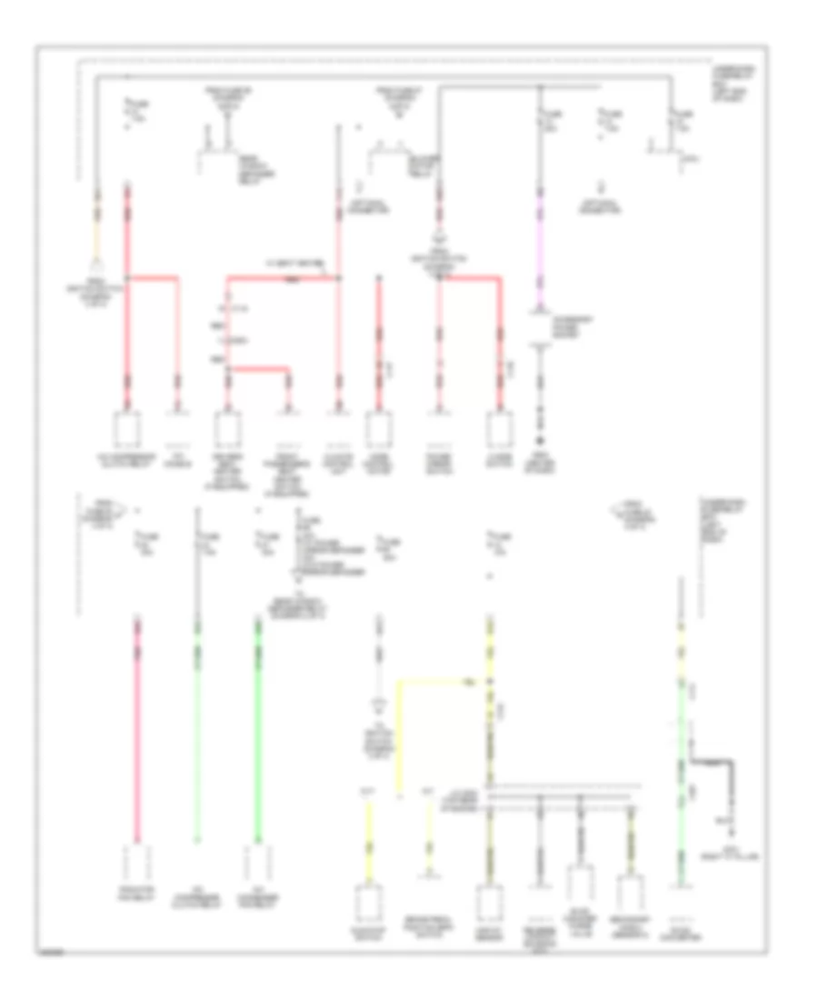
Power Distribution Wiring Diagram (3 of 4) for Honda CR-Z EX 2012
List of elements for Power Distribution Wiring Diagram (3 of 4) for Honda CR-Z EX 2012:
- A11
- A14
- A22
- A23
- Acc
- Acc on
- Ad1
- Ae2
- B18
- B19
- Backup light switch (m/t)
- C107
- C115
- C124
- C502
- Cvt
- D23
- Ecm/pcm
- Eps control unit
- From fuse 11 j (diagram 3 of 4)
- From under-dash fuse/relay box (diagram 2 of 4)
- Front passenger's air bag cut-off indicator
- Fuse 10a
- Fuse 15a
- Fuse 30a
- Fuse 7.5a
- Ignition switch
- Immobilizer keyless control unit
- J/c c120 (left center of dash)
- Lock
- M/t
- Micu
- Ods unit
- On acc
- Pgm-fi main relay 2
- Rear window wiper motor
- Red
- Srs unit
- Start
- Starter cut relay
- To fuse 12 (diagram 2 0f 4)
- To fuse 16 (diagram 3 of 4)
- To under-dash fuse/relay box (diagram 2 of 4)
- Under-dash fuse/relay box (left end of dash)
- Vsa modulator control unit
- Yaw rate acceleration sensor
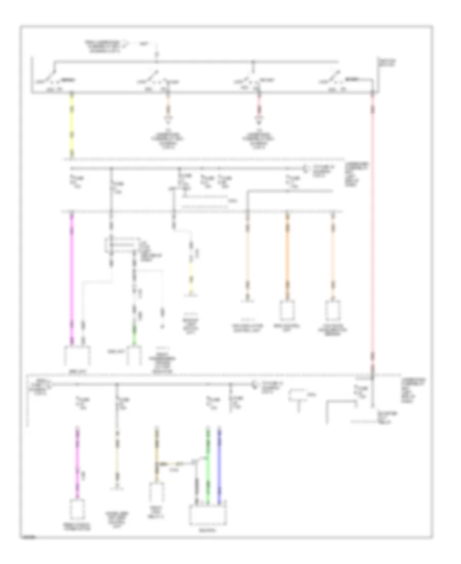
Power Distribution Wiring Diagram (4 of 4) for Honda CR-Z EX 2012
List of elements for Power Distribution Wiring Diagram (4 of 4) for Honda CR-Z EX 2012:
- (if equipped)
- (right "c"pillar)
- A32
- A35
- Aa4
- C107
- C111
- C122
- C403
- C901
- Cargo area light
- D32
- D42
- D48
- Driver vanity mirror light (if equipped)
- Etcs control relay
- Fog light relay (if equipped)
- From fuse 25 b (diagram 1 of 4)
- From fuse 27 k (diagram 4 of 4)
- Fuse 10a
- Fuse 15a
- Fuse 20a
- Fuse 30a
- Fuse 7.5a
- G701
- Individual map lights
- J/c c108 (left quarterpanel)
- Left rear tray light
- Lighting relay 1
- Lighting relay 2 (w/ hid)
- Mcm
- Mcm relay 1/ mcm relay 2
- Micu
- Nca
- Passenger vanity mirror light
- Pnk
- Relay 1
- Relay 2
- To blower motor relay (diagram 2 of 4)
- To fuse 30 (diagram 2 of 4)
- To lighting relay 1 (diagram 4 of 4)
- Under-dash fuse/relay box (left end of dash)
- Vsa modulator control unit
- W/ hid
POWER DOOR LOCKS
Power Door Locks Wiring Diagram (1 of 2) for Honda CR-Z EX 2012
List of elements for Power Door Locks Wiring Diagram (1 of 2) for Honda CR-Z EX 2012:
- A20
- A22
- A28
- Aa6
- B28
- B30
- C114
- C123
- Computer data
- D17
- D26
- D27
- D40
- Door lock knob
- Driver's door lock actuator/knob switch
- Driver's door unlock relay (left side of dash)
- Exterior lights system
- F10
- F11
- Fuse 10a
- Fuse 15a
- Fuse 20a
- G501 (left end of dash)
- G502 (center of dash)
- Horns system
- Hot at all times
- Hot in on or start
- Key
- Lines system
- Lock
- Micu
- N10
- Passenger's door lock actuator/knob switch
- Pnk
- Q18
- Q28
- Q29
- Red
- Trunk, tailgate, fuel doors system
- Under-dash fuse/relay box (left end of dash)
- Unlock
- Y14
Power Door Locks Wiring Diagram (2 of 2) for Honda CR-Z EX 2012
List of elements for Power Door Locks Wiring Diagram (2 of 2) for Honda CR-Z EX 2012:
- (rear of engine) g101
- A12
- Antenna
- Audio unit
- Blinking circuit
- Body controller area network transceiver
- C102
- C114
- C115
- Computer data lines system
- Driver's door switch (on left "b" pillar)
- G403 (left side of dash)
- G501 (left end of dash)
- G502 (center of dash)
- G503 (center of dash)
- Gauge control module
- High horn/ security horn (behind left side of front bumper)
- Ignition key switch
- Immobilizer- keyless control unit (in steering column)
- Lock
- Passenger's door switch (on right "b" pillar)
- Pnk
- Power window master switch
- Security hood switch (on engine compt hood latch assembly)
- Security indicator led
- Unlock
POWER MIRRORS
Power Mirrors Wiring Diagram for Honda CR-Z EX 2012
List of elements for Power Mirrors Wiring Diagram for Honda CR-Z EX 2012:
- (left end of dash)
- C114
- C118
- C123
- Defogger
- Defogger system
- Down/ left
- Down/ right
- Fuse 10 7.5a
- G501
- Hot in on
- Interior lights system
- Left
- Left power mirror (in left rearview mirror)
- Left/ right motor
- Light
- Pnk
- Power mirror switch
- Red
- Right
- Right power mirror (in right rearview mirror)
- Under-dash fuse/relay box (left end of dash)
- Up/ down motor
- Up/ left
- Up/ right
- Usa cvt & canada
- Usa m/t
- Y11
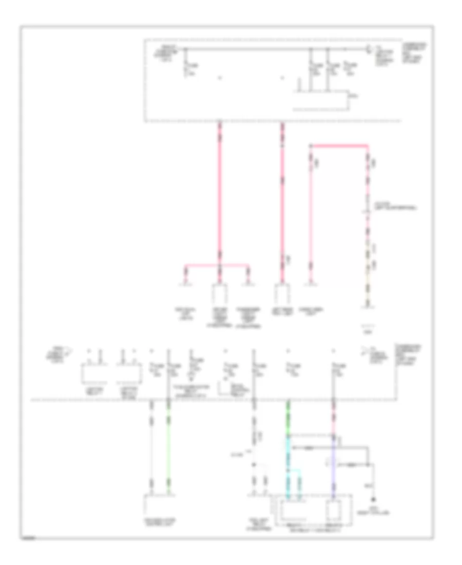
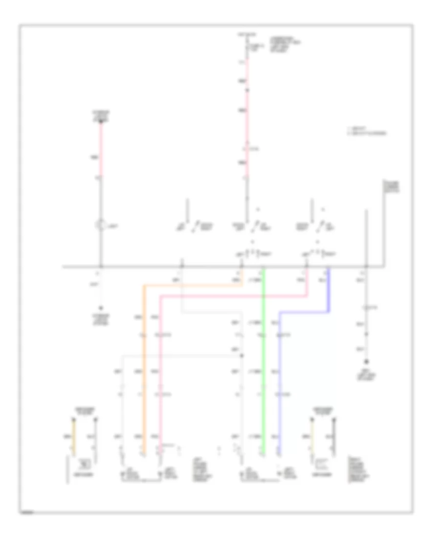
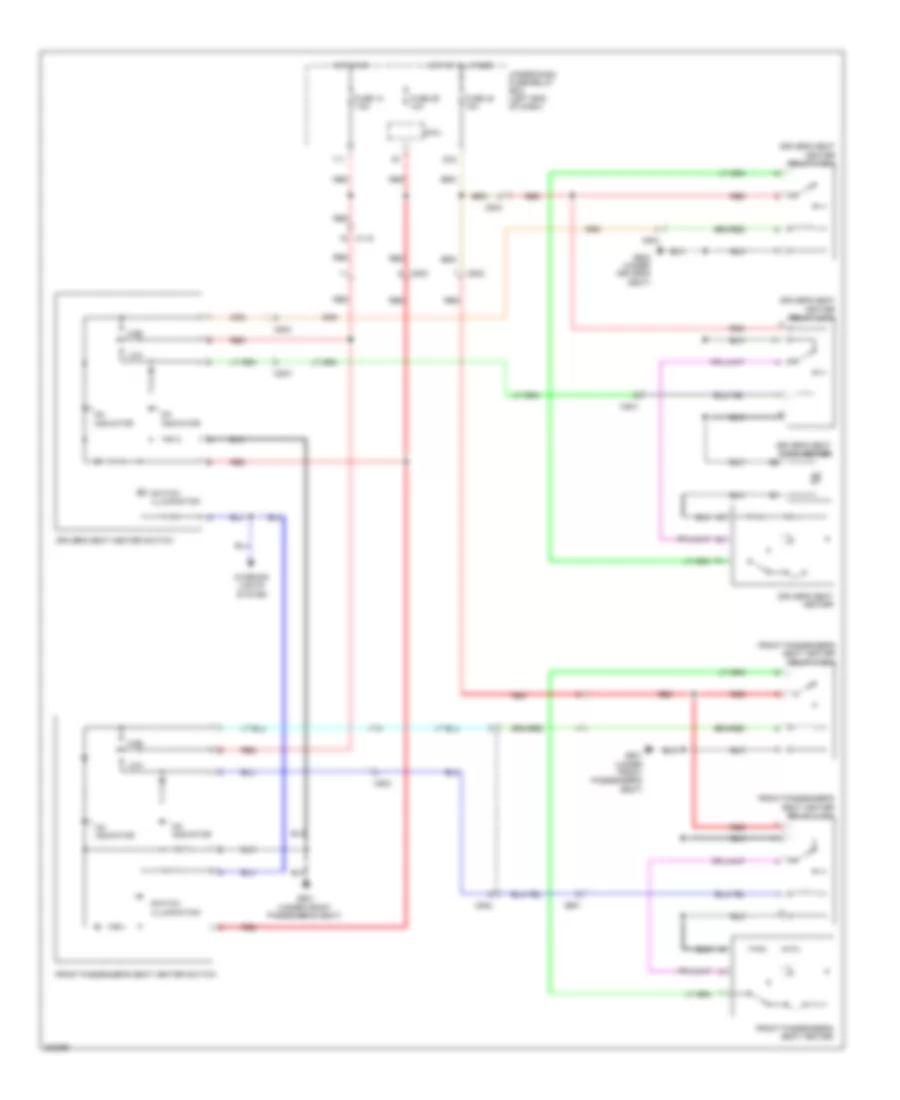
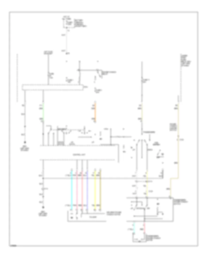
POWER SEATS
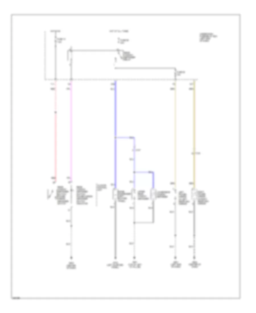
Heated Seats Wiring Diagram for Honda CR-Z EX 2012
List of elements for Heated Seats Wiring Diagram for Honda CR-Z EX 2012:
- C115
- C502
- C503
- C504
- C557
- D33
- Driver's seat back heater
- Driver's seat heater
- Driver's seat heater relay (high)
- Driver's seat heater relay (low)
- Driver's seat heater switch
- Front passenger's seat heater
- Front passenger's seat heater relay (high)
- Front passenger's seat heater relay (low)
- Front passenger's seat heater switch
- Fuse 10 7.5a
- Fuse 29 10a
- Fuse 40 10a
- G601 (under front passenger's seat)
- G602 (under driver's seat)
- High
- Hot at all times
- Hot in on
- Indicator
- Interior lights system
- Low
- Micu
- On indicator
- Red
- Switch illumination
- Under-dash fuse/relay box (left end of dash)
- Y11
POWER WINDOWS
Power Windows Wiring Diagram for Honda CR-Z EX 2012
List of elements for Power Windows Wiring Diagram for Honda CR-Z EX 2012:
- Battery terminal fuse box (on battery)
- C114
- C123
- Control unit
- Down
- Down (auto)
- Driver's
- Driver's power window motor
- F11
- Fuse 1 100a
- Fuse 1 15a
- Fuse 17 20a
- Fuse 3 20a
- Fuse 7.5a
- G501 (left end of dash)
- Hot at all times
- Hot in on or start
- Main switch
- Micu
- Off
- Passenger's
- Passenger's power window motor
- Passenger's power window switch
- Pnk
- Power window master switch
- Power window relay
- Pulsar
- Red
- Under- dash fuse/ relay box (left end of dash)
- Up (auto)
RADIO
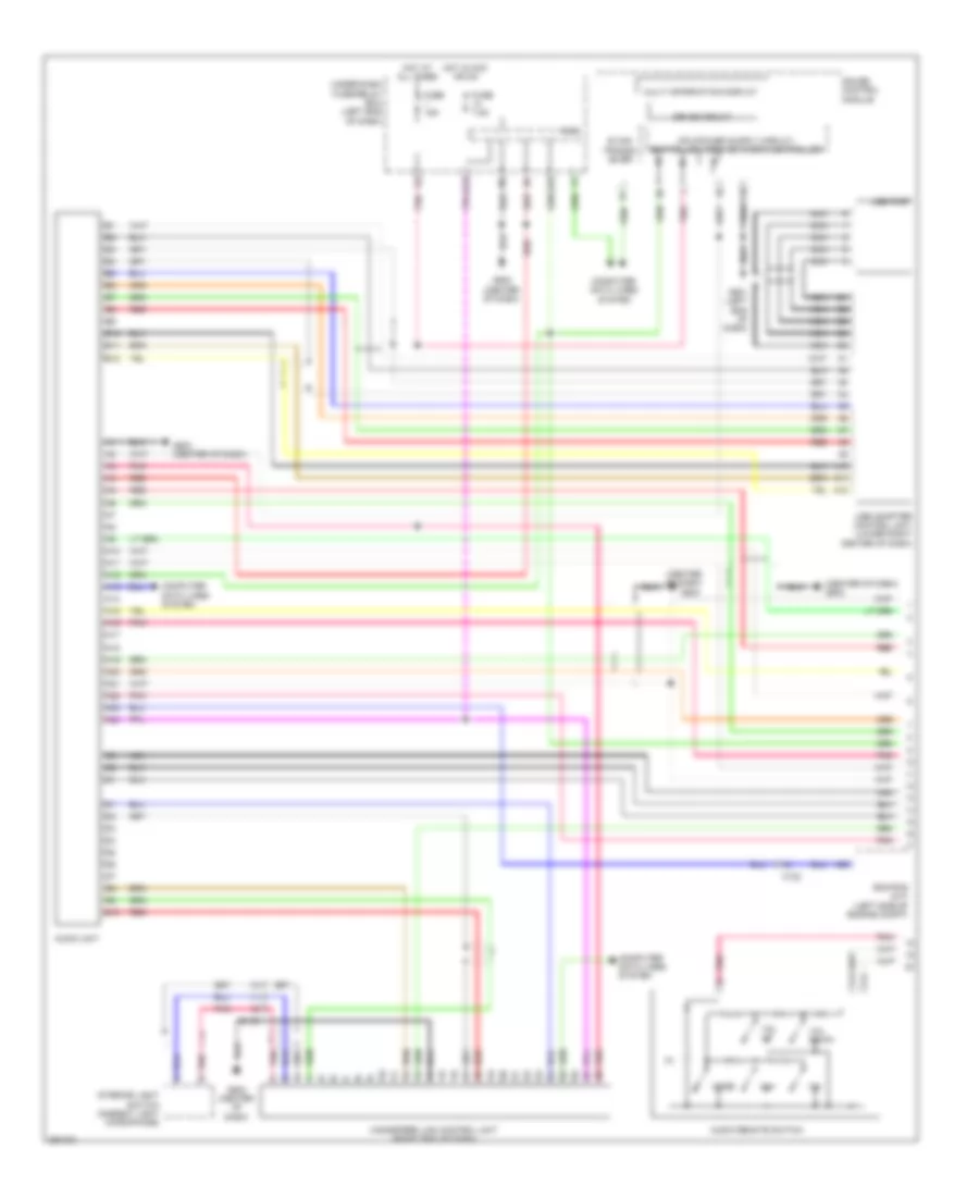
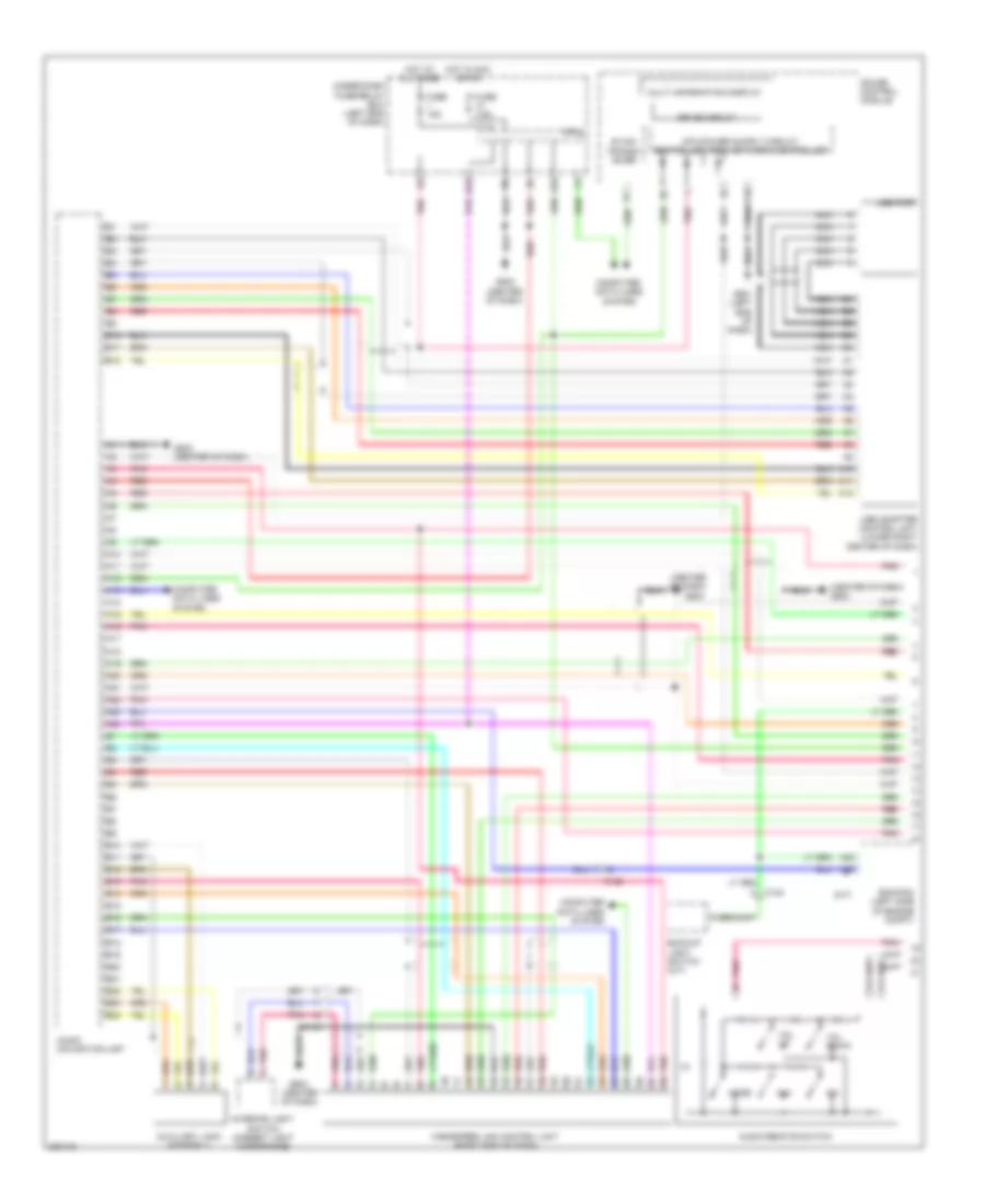
Radio Wiring Diagram, USA EX & CANADA without Navigation (1 of 2) for Honda CR-Z EX 2012
List of elements for Radio Wiring Diagram, USA EX & CANADA without Navigation (1 of 2) for Honda CR-Z EX 2012:
- (center of dash)
- (center of dash) g503
- (left end of dash)
- A10
- A11
- A12
- A13
- A14
- A15
- A16
- A17
- A18
- A19
- A20
- A21
- A22
- A23
- A24
- A29
- Audio remote switch
- Audio unit
- B can transc- iever
- C116
- C122
- Ch+
- Ch-
- Computer data lines system
- D10
- Drive circuit
- E10
- E11
- E12
- Ecm/pcm (m/t) (left side of engine compt)
- Fuse 15a
- Fuse 7.5a
- G501
- G502 (center of dash)
- G503
- G503 (center of dash)
- Gauge control module
- Handsfree link control unit (right end of dash)
- Hot at all times
- Hot in acc or on
- Interior light switch (ambient light microphone)
- Micu
- Mode
- Multi information display
- Nca
- Pnk
- Q29
- Q34
- Red
- Under-dash fuse/relay box (left end of dash)
- Usb adapter control unit (lower right center of dash)
- Usb port
- Vol down
- Vol up
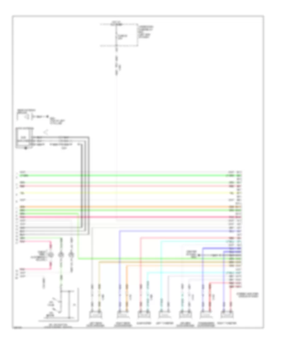
Radio Wiring Diagram, USA EX & CANADA without Navigation (2 of 2) for Honda CR-Z EX 2012
List of elements for Radio Wiring Diagram, USA EX & CANADA without Navigation (2 of 2) for Honda CR-Z EX 2012:
- (center of dash) g502
- A10
- A11
- A12
- A13
- A14
- A15
- A16
- A17
- A18
- A19
- A20
- A21
- Am/fm antenna
- Amplifier
- B10
- B11
- B12
- B13
- B14
- C103
- C106
- C114
- C115
- C123
- C14
- C301
- Cable reel (in steering column)
- Driver's door speaker
- Fuse 25 20a
- G801 (top of left "c" pillar)
- Hfl back
- Hfl navigation voice control switch
- Hfl talk
- Hot at all times
- Left rear door speaker
- Left tweeter
- Nca
- Passenger's door speaker
- Pnk
- Rear antenna ground
- Red
- Right rear door speaker
- Right tweeter
- Stereo amplifier (middle of dash)
- Sub
- Subwoofer
- Under-dash fuse/relay box (left end of dash)
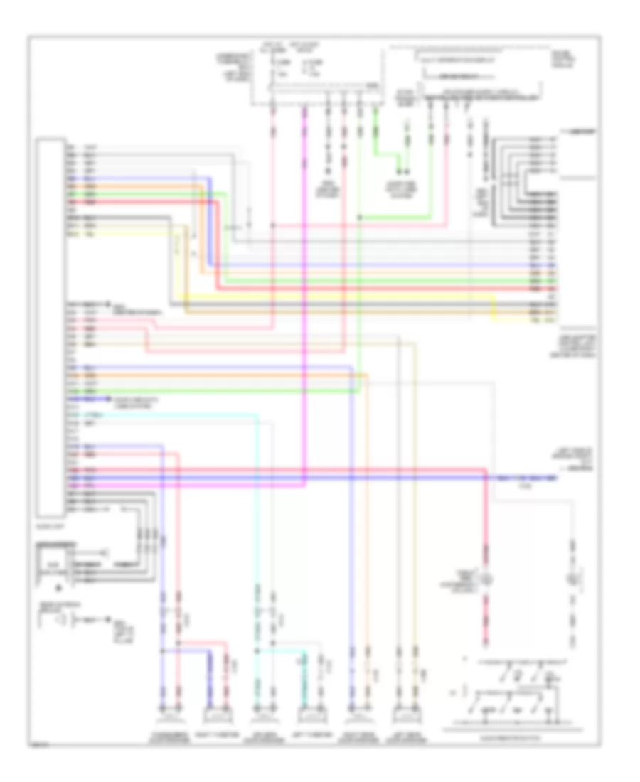
Radio Wiring Diagram, USA Except EX without Navigation for Honda CR-Z EX 2012
List of elements for Radio Wiring Diagram, USA Except EX without Navigation for Honda CR-Z EX 2012:
- (left side of engine compt) (m/t) ecm/pcm
- A10
- A11
- A12
- A13
- A14
- A15
- A16
- A17
- A18
- A19
- A20
- A21
- A22
- A23
- A24
- A29
- Am/fm antenna
- Amplifier
- Audio remote switch
- Audio unit
- B can transc- iever
- C106
- C114
- C115
- C122
- C123
- C301
- Cable reel (in steering column)
- Ch+
- Ch-
- Computer data lines system
- Drive circuit
- Driver's door speaker
- E10
- E11
- E12
- Fuse 15a
- Fuse 7.5a
- G501 (left end of dash)
- G502 (center of dash)
- G503 (center of dash)
- G801 (top of left "c" pillar)
- Gauge control module
- Hot at all times
- Hot in acc or on
- Left rear door speaker
- Left tweeter
- Micu
- Mode
- Multi information display
- Nca
- Passenger's door speaker
- Pnk
- Q29
- Q34
- Rear antenna ground
- Red
- Right rear door speaker
- Right tweeter
- Sub
- Under-dash fuse/relay box (left end of dash)
- Usb adapter control unit (lower right center of dash)
- Usb port
- Vol down
- Vol up
Radio Wiring Diagram, with Navigation (1 of 2) for Honda CR-Z EX 2012
List of elements for Radio Wiring Diagram, with Navigation (1 of 2) for Honda CR-Z EX 2012:
- (center of dash)
- (center of dash) g503
- (left end of dash)
- (m/t)
- A10
- A11
- A12
- A13
- A14
- A15
- A16
- A17
- A18
- A19
- A20
- A21
- A22
- A23
- A24
- A29
- A32
- Audio navigation unit
- Audio remote switch
- Auxiliary jack assembly
- B can transc- iever
- B10
- B11
- B12
- B13
- B14
- B15
- B16
- B17
- B18
- B19
- B20
- B21
- B22
- B23
- B24
- Backup light switch (m/t)
- C116
- C122
- C124
- Ch+
- Ch-
- Computer data lines system
- Drive circuit
- E10
- E11
- E12
- Ecm/pcm (left side of engine compt)
- Fuse 15a
- Fuse 7.5a
- G501
- G502 (center of dash)
- G503
- G503 (center of dash)
- Gauge control module
- Handsfree link control unit (right end of dash)
- Hot at all times
- Hot in acc or on
- Interior light switch (ambient light microphone)
- Micu
- Mode
- Multi information display
- Nca
- Pnk
- Q29
- Q34
- Red
- Under-dash fuse/relay box (left end of dash)
- Usb adapter control unit (lower right center of dash)
- Usb port
- Vol down
- Vol up
Radio Wiring Diagram, with Navigation (2 of 2) for Honda CR-Z EX 2012
List of elements for Radio Wiring Diagram, with Navigation (2 of 2) for Honda CR-Z EX 2012:
- (center of dash) g502
- A10
- A11
- A12
- A13
- A14
- A15
- A16
- A17
- A18
- A19
- A20
- A21
- Am/fm antenna
- Audio navigation unit
- B10
- B11
- B12
- B13
- B14
- B17
- C103
- C106
- C114
- C115
- C122
- C123
- C124
- C14
- C15
- C301
- Cable reel (in steering column)
- Climate control module
- D10
- D11
- D12
- D18
- Driver's door speaker
- Fuse 25 20a
- G101 (rear of engine)
- G502 (center of dash)
- G503 (center of dash)
- G801 (top of left "c" pillar)
- Gps antenna
- Hfl back
- Hfl navigation voice control switch
- Hfl talk
- Hot at all times
- J/c c204
- Left rear door speaker
- Left tweeter
- Micu
- Nca
- Passenger's door speaker
- Pnk
- Rear antenna ground
- Red
- Right rear door speaker
- Right tweeter
- Stereo amplifier (middle of dash)
- Sub amplifier
- Subwoofer
- Transmission range switch (cvt) (on transmission housing)
- Under-dash fuse/relay box (left end of dash)
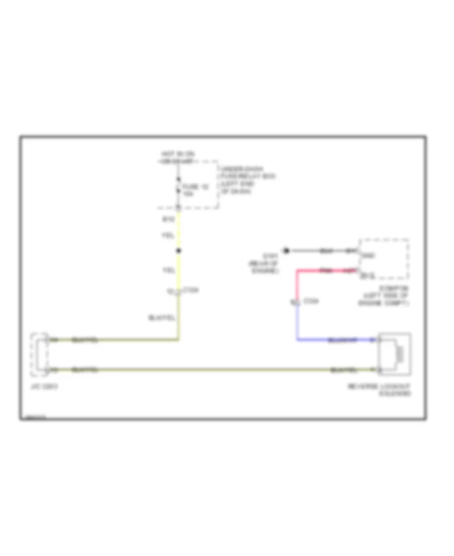
SHIFT INTERLOCK
Reverse Lockout Wiring Diagram for Honda CR-Z EX 2012
List of elements for Reverse Lockout Wiring Diagram for Honda CR-Z EX 2012:
- A27
- B12
- C124
- Ecm/pcm (left side of engine compt)
- Fuse 12 10a
- G101 (rear of engine)
- Gnd
- Hot in on or start
- J/c c203
- Pnk
- Reverse lockout solenoid
- Rvs
- Under-dash fuse/relay box (left end of dash)
Shift Interlock Wiring Diagram for Honda CR-Z EX 2012
List of elements for Shift Interlock Wiring Diagram for Honda CR-Z EX 2012:
- A/t gear position indicator panel light/park pin switch/shift lock solenoid
- A17
- A18
- A24
- A25
- A27
- A34
- A35
- A40
- App sensor (left side of dash)
- B13
- B14
- B26
- B30
- Brake pedal position switch (top of brake pedal assembly)
- C115
- C122
- C124
- Computer data lines system
- Ecm/pcm (left side of engine compt)
- Eld
- Fuse 14 7.5a
- Fuse 22 7.5a
- Fuse 24 10a
- G101 (rear of engine)
- G502 (center of dash)
- G601 (under front passenger's seat)
- Hot at all times
- Hot in acc or on
- Hot in on or start
- Ignition key switch
- Immobilizer keyless control unit (in steering column)
- J/c c204
- Key interlock solenoid
- Micu
- Park pin switch
- Q18
- Q34
- Red
- Sensor
- Shift lock solenoid
- Transmission range switch (on transmission housing)
- Under-dash fuse/relay box (left end of dash)
- Y15
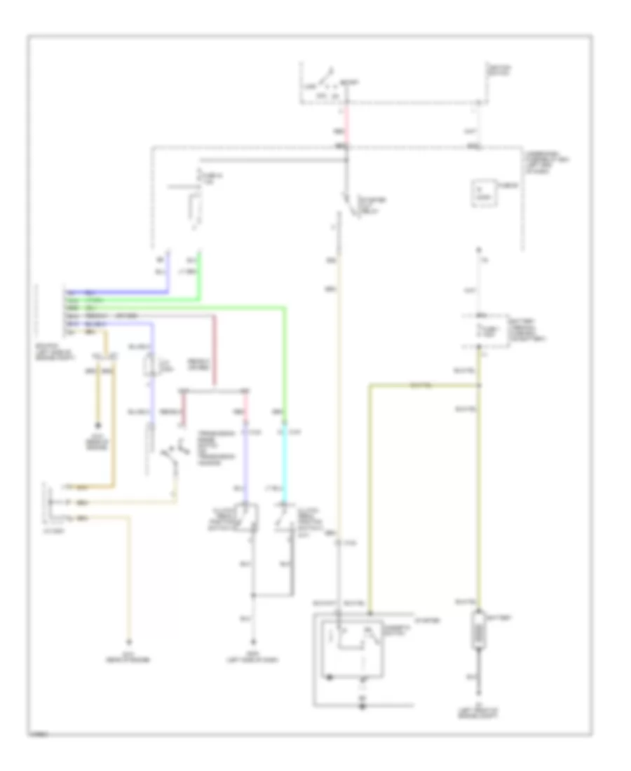
STARTING/CHARGING
Starting Wiring Diagram for Honda CR-Z EX 2012
List of elements for Starting Wiring Diagram for Honda CR-Z EX 2012:
- (m/t)
- (or red)
- 50a
- 7.5a
- A/t
- A12
- Ac2
- Acc
- Ae2
- B12
- B13
- B36
- B39
- Battery
- Battery terminal fuse box (on battery)
- C124
- C127
- Clutch pedal position switch a
- Clutch pedal position switch c
- Cvt
- Ecm/pcm (left side of engine compt)
- Fuse 1 100a
- Fuse 44
- Fuse 60
- G1 (left front of engine compt)
- G101 (rear of engine)
- G403 (left side of dash)
- Ignition switch
- J/c c204
- Lock
- M/t
- Magnetic switch
- N d
- Red
- Start
- Starter
- Starter cut relay
- Transmission range switch (on transmission housing)
- Under-dash fuse/relay box (left end of dash)
SUPPLEMENTAL RESTRAINTS
Supplemental Restraints Wiring Diagram (1 of 3) for Honda CR-Z EX 2012
List of elements for Supplemental Restraints Wiring Diagram (1 of 3) for Honda CR-Z EX 2012:
- (left side of center console) g504
- A10
- A11
- A12
- A13
- A14
- A15
- A16
- A17
- A18
- A19
- A20
- A21
- A22
- A23
- A24
- A25
- A26
- A27
- A28
- A29
- A30
- A31
- C101
- C112
- Cable reel (in steering wheel)
- Computer data lines system
- Driver's air bag first/ second inflator (in steering wheel)
- Front passenger's air bag first / second inflator (behind right side of dash)
- Fuse 10a
- Fuse 7.5a
- Hot in on or start
- J/c c120 (left center of dash)
- Left front impact sensor (behind left side of front bumper)
- Micu
- Pnk
- Red
- Right front impact sensor (behind right side of front bumper)
- Srs unit (under middle of dash)
- Under-dash fuse/relay box (left end of dash)
Supplemental Restraints Wiring Diagram (2 of 3) for Honda CR-Z EX 2012
List of elements for Supplemental Restraints Wiring Diagram (2 of 3) for Honda CR-Z EX 2012:
- (base of left "b" pillar) left side impact sensor (2nd)
- (base of right "b" pillar) right side impact sensor (2nd)
- (driver's seat belt buckle assembly) driver's seat belt buckle switch
- (front passenger's seat belt buckle assembly) front passenger's seat belt buckle switch
- (middle of left door sill) left side impact sensor (1st)
- (middle of right door sill) right side impact sensor (1st)
- (under left side of driver's seat) driver's seat position sensor
- (under middle of dash)
- B10
- B11
- B12
- B13
- B14
- B15
- B16
- B17
- B18
- B19
- B20
- B21
- B22
- B23
- B24
- B25
- B26
- B27
- B28
- B29
- B30
- B31
- B32
- B33
- B34
- B35
- B36
- B37
- B38
- B39
- C105
- C501
- Driver's seat belt tensioner (base of driver's "b" pillar)
- Driver's side air bag inflator (outer side of driver's seat back)
- Front passenger's seat belt tensioner (base of front passenger's "b" pillar)
- Front passenger's side air bag inflator (outer side of front passenger's seat back)
- G601 (under front passenger's seat)
- G602 (under driver's seat)
- Left side curtain air bag inflator (top of left "c" pillar)
- Pnk
- Red
- Right side curtain air bag inflator (top of right "c" pillar)
- Srs unit
Supplemental Restraints Wiring Diagram (3 of 3) for Honda CR-Z EX 2012
List of elements for Supplemental Restraints Wiring Diagram (3 of 3) for Honda CR-Z EX 2012:
- (under left side of right front seat) front passenger's weight sensor (front inner side)
- (under right side of right front seat) front passenger's weight sensor (front outer side)
- C115
- C502
- Compulsory turning on circuit
- Computer data lines system
- Controller area network controller
- F can tranceiver
- F-can h
- F-can l
- Fall-safe circuit
- Front passenger's air bag cut-off indicator
- G501 (left end of dash)
- G601 (under front passenger's seat)
- Gauge control module
- Indicator drive circuit
- Interior lights system
- Nca
- Ods unit (outer side of right front seat back)
- Opds sensor
- Pnk
- Red
- Seat belt reminder ind
- Side air bag cut-off ind
- Srs ind
TRANSMISSION
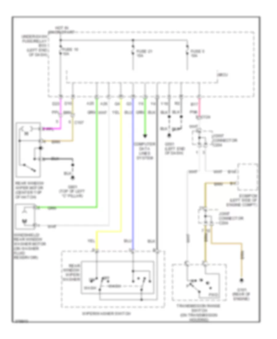
Transmission Wiring Diagram (1 of 2) for Honda CR-Z EX 2012
List of elements for Transmission Wiring Diagram (1 of 2) for Honda CR-Z EX 2012:
- (shift lock solenoid:base of a/t shift lever) (park pin switch:under center console) a/t gear position indicator panel light/park pin switch/shift lock solenoid
- (top of brake pedal assembly) brake pedal position switch
- A17
- A18
- A24
- A25
- A27
- A30
- A31
- A32
- A34
- A35
- A36
- A37
- A40
- A43
- A44
- B10
- B12
- B13
- B14
- B17
- B18
- B19
- B21
- B22
- B26
- B28
- B30
- B34
- B41
- B42
- B43
- B44
- C115
- C122
- C124
- C201
- C36
- C39
- C40
- C43
- C44
- Computer data lines system
- Cvt clutch pressure control solenoid valve (on transmission)
- Cvt drive pulley pressure control solenoid valve (on transmission)
- Cvt driven pulley pressure control solenoid valve (on transmission)
- Ecm/pcm (left side of engine compt)
- Eld
- Engine controls system
- Fuse 20 15a
- Fuse 22 7.5a
- Fuse 24 10a
- Fuse 39 15a
- Fuse 7 10a
- G101 (rear of engine)
- Hot at all times
- Hot in on or start
- Inhibitor solenoid (on transmission)
- J/c c204
- Micu
- Pgm-fi main relay 1
- Pnk
- Shift lock solenoid
- Under-dash fuse/relay box (left end of dash)
Transmission Wiring Diagram (2 of 2) for Honda CR-Z EX 2012
List of elements for Transmission Wiring Diagram (2 of 2) for Honda CR-Z EX 2012:
- 10v
- 3-mode switch
- A/t gear position indicator drive circuit
- App sensor (left side of dash)
- C118
- C122
- Cable reel (in steering column)
- Circuit -izing stabil-
- Circuit dimming a/t
- Computer
- Cruise control combination switch
- Cvt input shaft (drive pulley) speed sensor (on transmission housing)
- Cvt output shaft (driven pulley) speed sensor (on transmission housing)
- Data lines system
- Dimming circuit
- Display
- Drive circuit
- Econ
- Engine controls system
- F-can transceiver
- Fuse 1 15a
- Fwd
- G501 (left end of dash)
- Gauge control module (behind instrument cluster)
- Hot at all times
- J/c 204
- J/c c203
- J/c c204
- Micu
- Multi- information
- Normal
- Paddle shifter (+) (upshift switch)
- Paddle shifter (-) (downshift switch)
- Pnk
- Sport
- T10
- Transmission range switch (on transmission housing)
- Under- dash fuse/ relay box (left end of dash)
- Vehicle speed sensor (on trans- axle)
TRUNK, TAILGATE, FUEL DOOR
Hatch Release Wiring Diagram for Honda CR-Z EX 2012
List of elements for Hatch Release Wiring Diagram for Honda CR-Z EX 2012:
- C106
- C107
- D17
- Fuse 29 10a
- Fuse 45 20a
- G501 (left end of dash)
- G801 (top of left "c" pillar)
- Hatch latch switch (lower center of hatch)
- Hatch outer handle switch
- Hatch release actuator (lower center of hatch)
- Hatch release actuator relay
- Hot at all times
- Micu
- Pnk
- Q27
- Red
- Under-dash fuse/relay box (left end of dash)
WARNING SYSTEMS
Chime Wiring Diagram for Honda CR-Z EX 2012
List of elements for Chime Wiring Diagram for Honda CR-Z EX 2012:
- (driver's seat belt buckle assembly) driver's seat belt buckle switch
- (front passenger's seat belt buckle assembly) front passenger's seat belt buckle switch
- 10v stabilizing circuit
- A36
- A37
- Amp
- Auto
- Brake system ind
- C106
- C107
- C115
- Combination light
- Compulsory turning-off circuit
- Compulsory turning-on circuit
- Computer data lines system
- D17
- D26
- D27
- D45
- Dimming circuit
- Door ind
- Driver's door switch (on left "b" pillar)
- Ecm/pcm (left side of engine compt)
- F-can transceiver
- Fall-scale circuit
- Fuse 1 15a
- Fuse 22 7.5a
- G501 (left end of dash)
- G502 (center of dash)
- G601 (under front passenger's seat)
- G602 (under driver's seat)
- G801 (top of left "c" pillar)
- Gauge control module
- Hatch latch switch (lower center of hatch)
- Head
- Hot at all times
- Hot in on or start
- Ignition key switch
- Indicator drive circuit
- Interior lights system
- Lights-on ind
- Low oil pressure ind
- Micu
- Off
- Oil pressure switch (near oil filter)
- Park
- Parking brake switch (at base of park lever)
- Passenger's door switch (on right "b" pillar)
- Pnk
- Q10
- Q11
- Q13
- Q18
- Q19
- Red
- Seat belt reminder ind
- Speaker
- Srs unit (under middle of dash)
- Switch
- Under-dash fuse/relay box (left end of dash)
Tire Pressure Monitoring Wiring Diagram for Honda CR-Z EX 2012
List of elements for Tire Pressure Monitoring Wiring Diagram for Honda CR-Z EX 2012:
- Circuit
- Computer data lines system
- Display unit multi-information tpms indicator
- F-can transceiver
- Fuse 15a
- Fuse 7.5a
- G502 (center of dash)
- Gauge control module
- Hot at all times
- Hot in on or start
- Indicator drive
- Low tire pressure indicator
- Micu
- Pnk
- Q31
- System message indicator
- Tpms control unit (left center of dash)
- Under-dash fuse/relay box (left end of dash)
WIPER/WASHER
Front Wiper/Washer Wiring Diagram for Honda CR-Z EX 2012
List of elements for Front Wiper/Washer Wiring Diagram for Honda CR-Z EX 2012:
- 5v control unit
- A19
- A23
- A25
- A26
- Adjuster sensitivity rainfall
- B-can tranceiver
- C102
- C103
- Computer data lines system
- Drive circuit
- Fuse 1 15a
- Fuse 21 15a
- Fuse 22 7.5a
- Fuse 56 30a
- G201 (right front of engine compt)
- G401 (left front of engine compt)
- G501 (left end of dash)
- G502 (center of dash)
- Gauge control module
- High
- Hot at all times
- Hot in on or start
- Int
- Low
- Micu
- Mist
- Multi information display
- Off
- Pnk
- Red
- Under-dash fuse/relay box (left end of dash)
- Wash
- Washer fluid level switch (canada)
- Windshield washer
- Windshield wiper
- Windshield wiper motor (left rear of luggage compt)
- Windshield/ rear window washer motor (on washer fluid reservoir)
- Wiper/ washer switch
- Y16
Rear Wiper/Washer Wiring Diagram for Honda CR-Z EX 2012
List of elements for Rear Wiper/Washer Wiring Diagram for Honda CR-Z EX 2012:
- A25
- A26
- B14
- B17
- C107
- C124
- Computer data lines system
- D10
- D23
- Ecm/pcm (left side of engine compt)
- Fuse 16 10a
- Fuse 21 15a
- Fuse 5 10a
- Fwd
- G101 (rear of engine)
- G501 (left end of dash)
- G801 (top of left "c" pillar)
- Hot in on or start
- Joint connector c204
- Micu
- Off
- Pnk
- Rear window wiper motor (center top of hatch)
- Rear window wiper/ washer
- Transmission range switch (on transmission housing)
- Under-dash fuse/relay box (left end of dash)
- Wash
- Windshield/ rear window washer motor (on washer fluid reservoir)
- Wiper/washer switch
- Y16

 Čeština
 Dansk
Dansk Deutsch
 Ελληνικά
 English
 English
 Español
 Suomi
Suomi Français
 Français
 עברית
עברית Hrvatski
 Magyar
 日本語
日本語 한국어
한국어 Nederlands
 Polski
 Português
 Português
 Română
 Русский
 Slovenčina
 Slovenščina
 Svenska
 Türkçe
 中文 (中国)