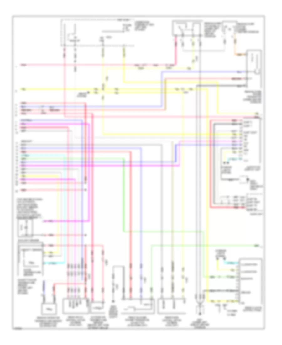
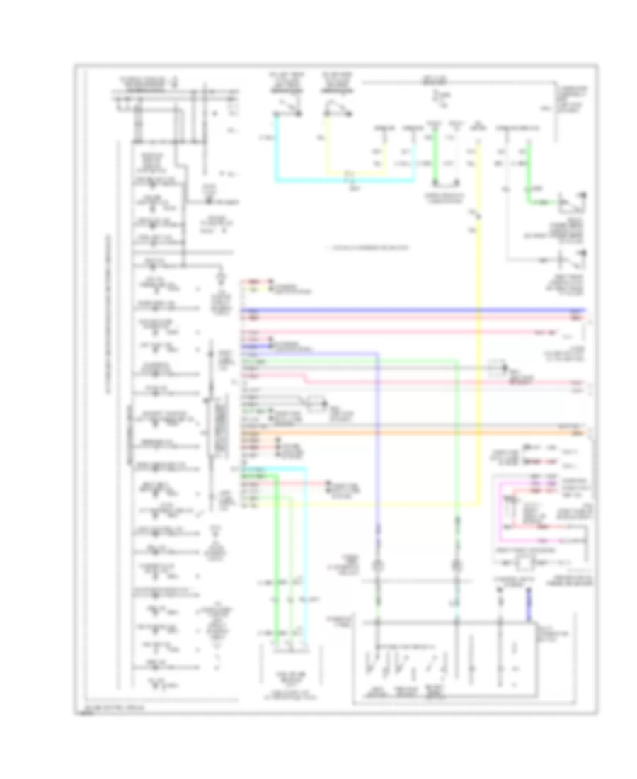
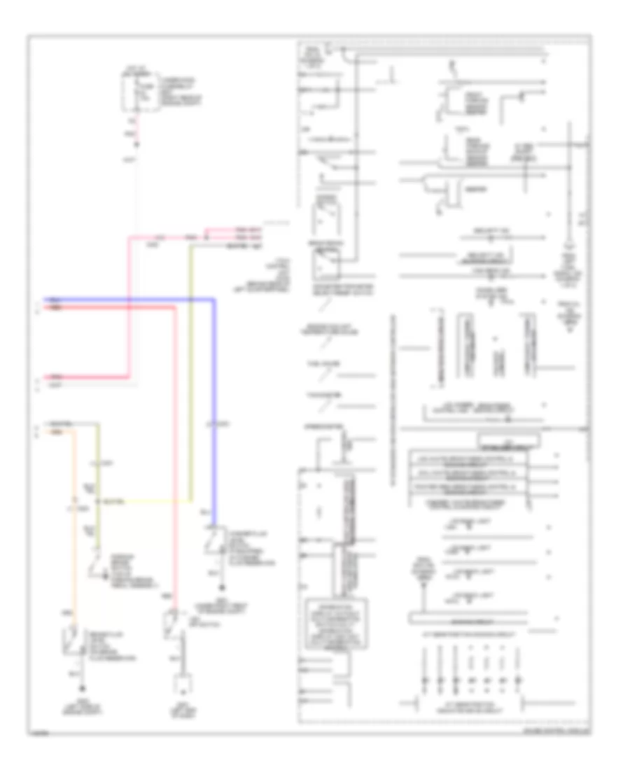
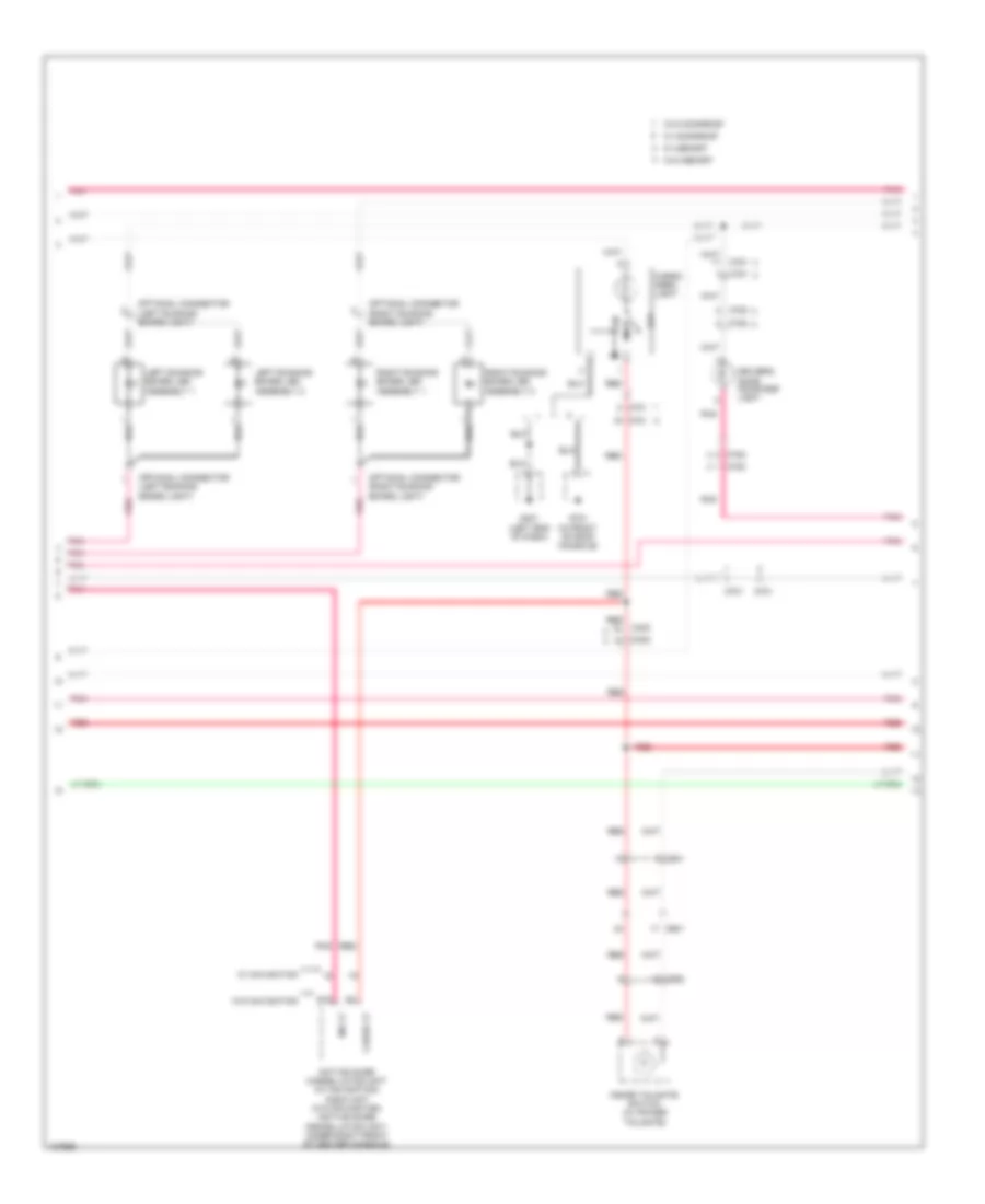
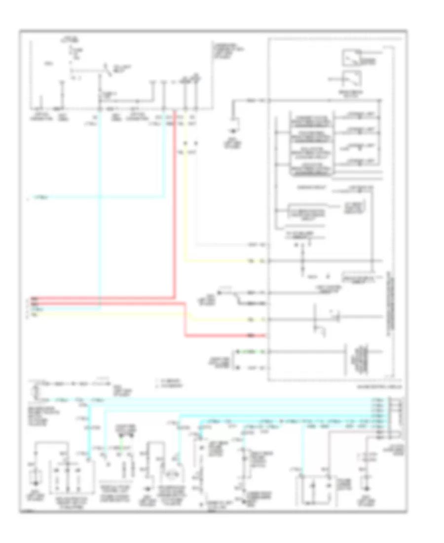
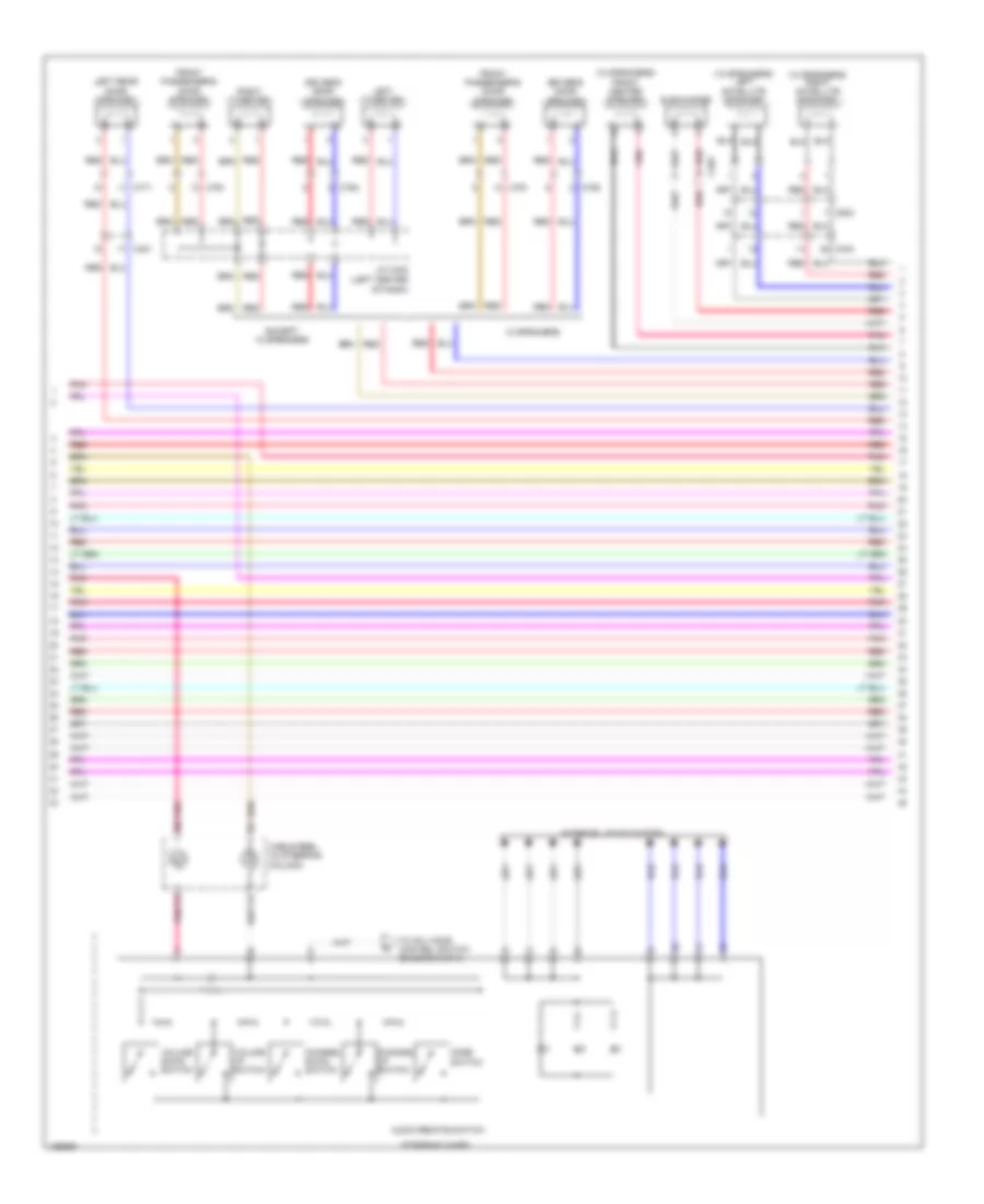
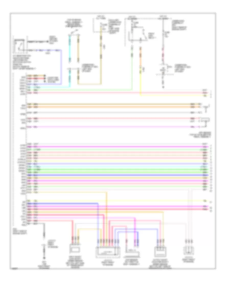
AIR CONDITIONING
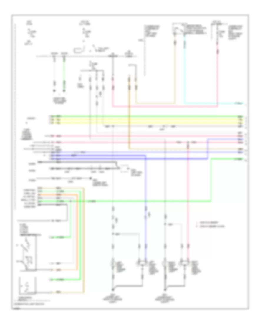
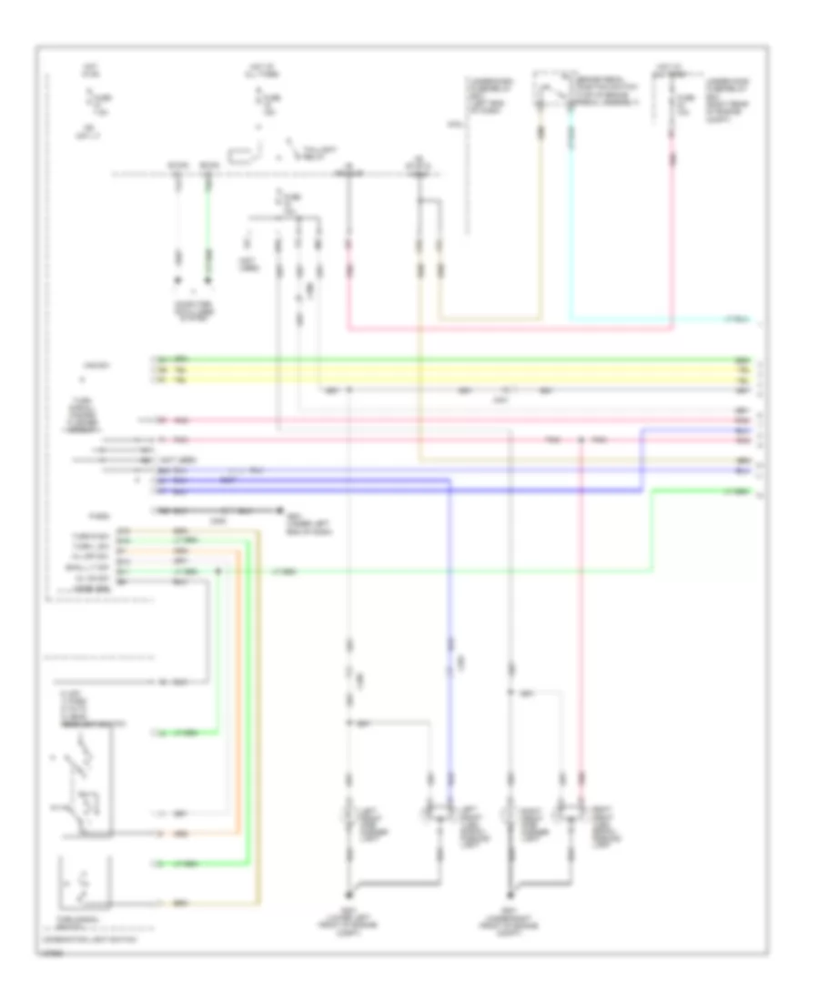
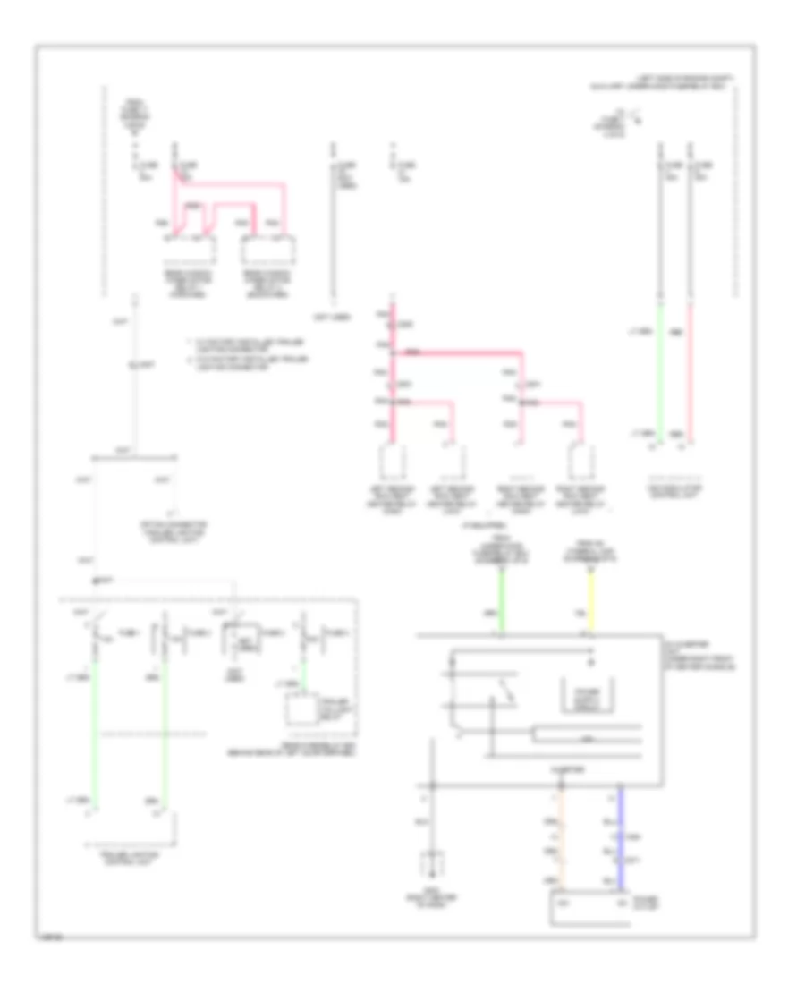
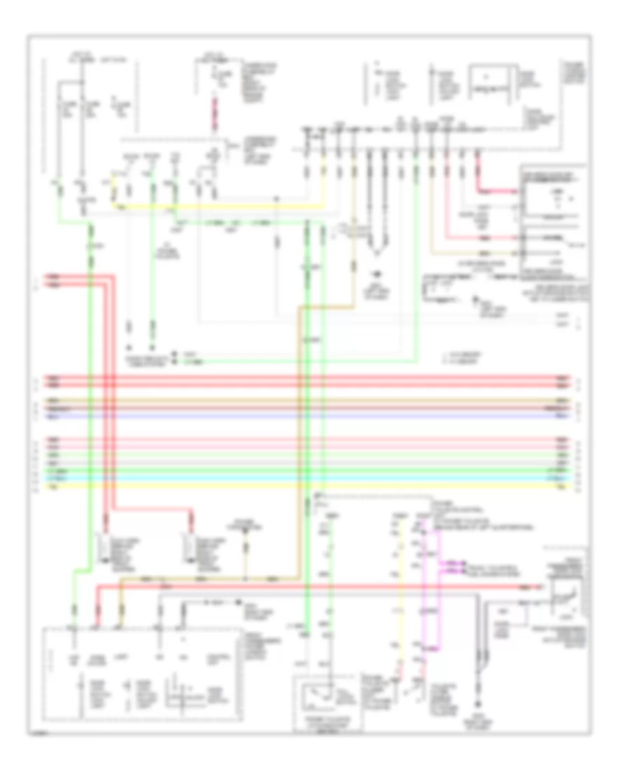
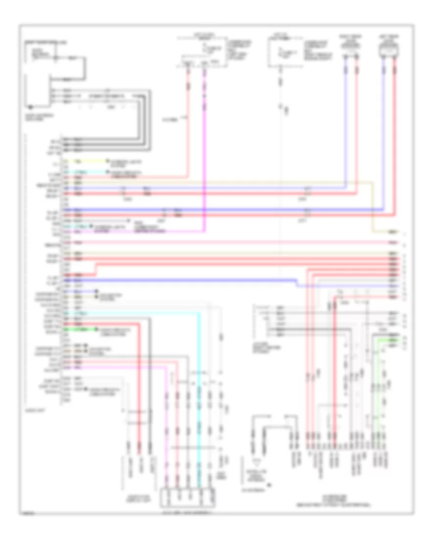
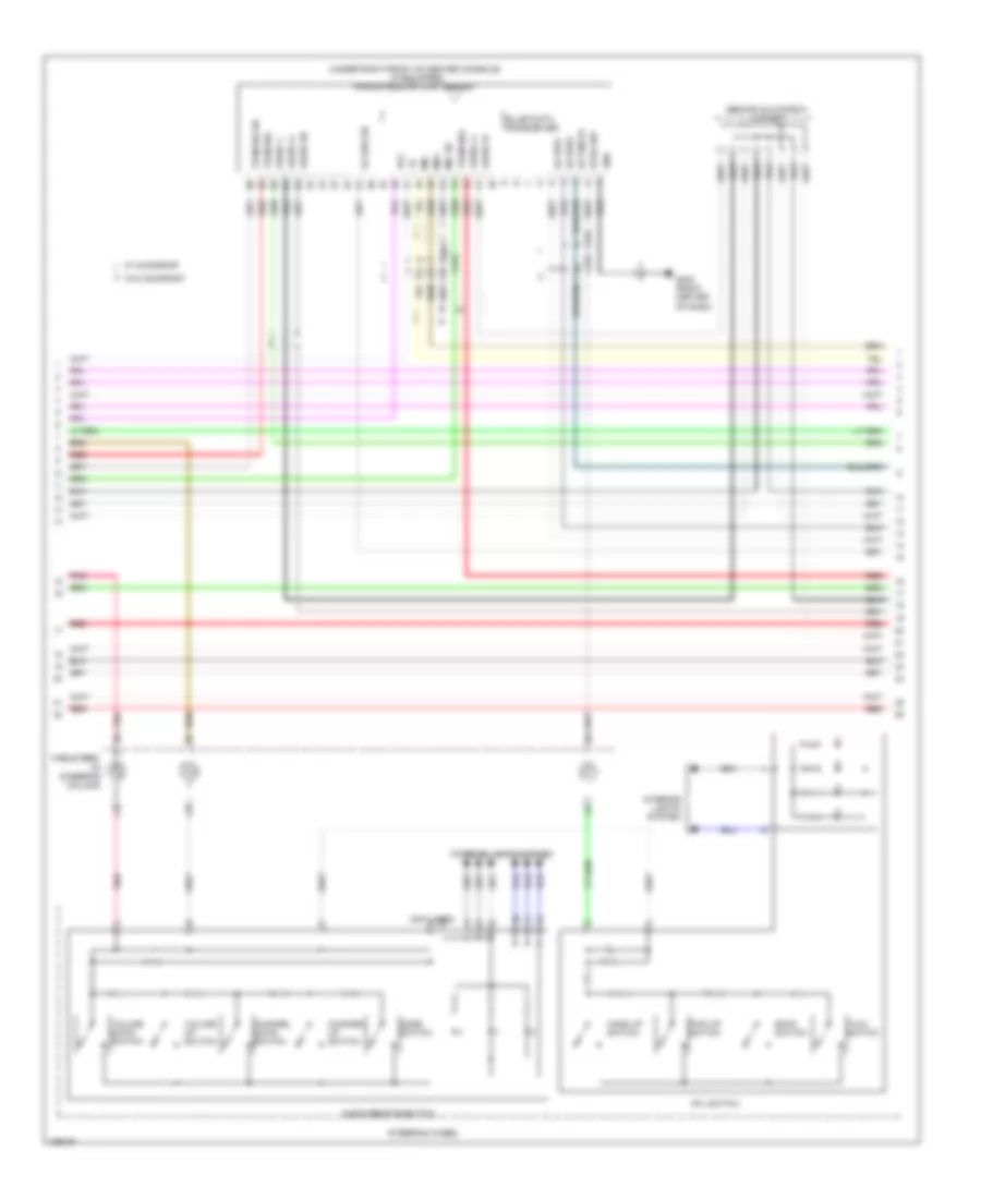
Automatic A/C Wiring Diagram (1 of 3) for Honda Pilot EX-L 2014
 https://portal-diagnostov.com/license.html
Automotive Electricians Portal FZCO
Automotive Electricians Portal FZCO
https://portal-diagnostov.com/license.html
https://portal-diagnostov.com/license.html
Automotive Electricians Portal FZCO
Automotive Electricians Portal FZCO
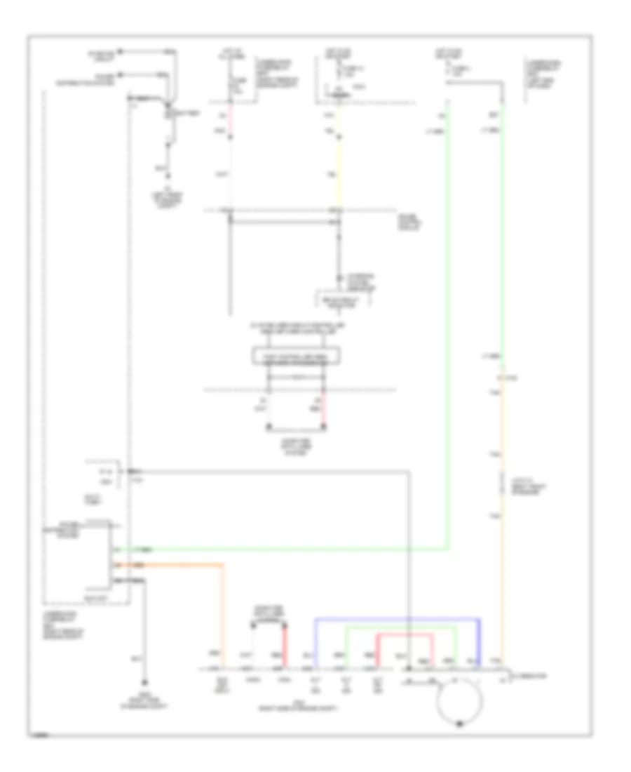
List of elements for Automatic A/C Wiring Diagram (1 of 3) for Honda Pilot EX-L 2014:
- A/c pressure sensor
- A/c pressure sensor (right rear of
- A10
- A11
- A12
- A13
- A14
- A15
- A16
- A17
- A18
- A19
- A20
- A21
- A22
- A23
- A24
- A25
- A26
- A27
- A28
- A29
- A30
- A31
- A32
- A33
- A34
- A35
- A36
- Amd-p
- Auxiliary under-hood
- B-can hi
- B-can lo
- B10
- B11
- B12
- Bus data
- C303
- C451
- C461
- Climate control unit
- Common potential
- Computer data lines system
- Defogger system
- Disp-clk
- Disp-si
- Driver's air mix control motor (left side of hvac unit)
- Driver's air mix cool
- Driver's air mix hot
- Driver's air mix potential
- Engine compt)
- Evaporator temp sens
- Fr power transistor ctrl
- Fresh
- Front blower feed back
- Front evaporator temperature sensor (left side of front hvac evaporator)
- Front mode control motor (lower right side of hvac unit)
- Front mode ctrl mode 1
- Front mode ctrl mode 2
- Front mode ctrl mode 3
- Front mode ctrl mode 4
- Front mode def
- Front mode vent
- Front passenger's air mix control motor
- Frs
- Fuse 30a
- Fuse/relay box (left side of engine compt)
- G403 (right center of dash)
- Ground
- Hot at all times
- Humidity sensor
- Ig2
- Illumination+
- Illumination-
- In-car temp sens
- Interior lights system
- M-cool
- M-def
- M-hot
- M-vent
- Mode 1
- Mode 2
- Mode 3
- Mode 4
- Outside air temp sens
- Pass air mix potential
- Passenger's air mix cool
- Passenger's air mix hot
- Pnk
- Rear air mix cold
- Rear air mix hot
- Rear air mix potential
- Rear blower feed back
- Rear mode heat
- Rear mode vent
- Rear window defogger rly
- Rec
- Recirculate
- Recirculation control motor (left side of blower unit)
- Recirculation ctrl mode 1
- Recirculation ctrl mode 2
- Recirculation ctrl mode 3
- Red
- Rr evaporator temp sens
- Rr power transistor ctrl
- S-com
- S5v
- Sensor common ground
- Sunlight sens
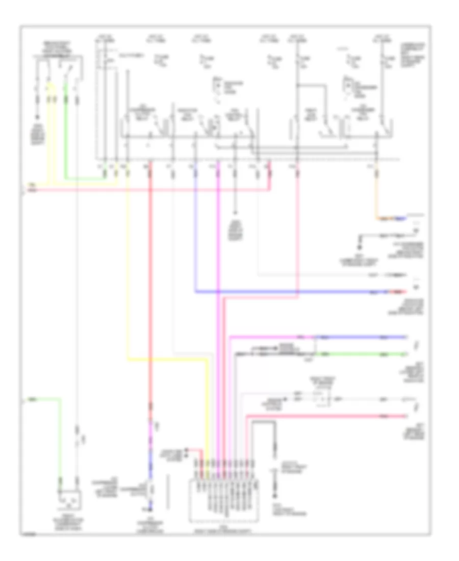
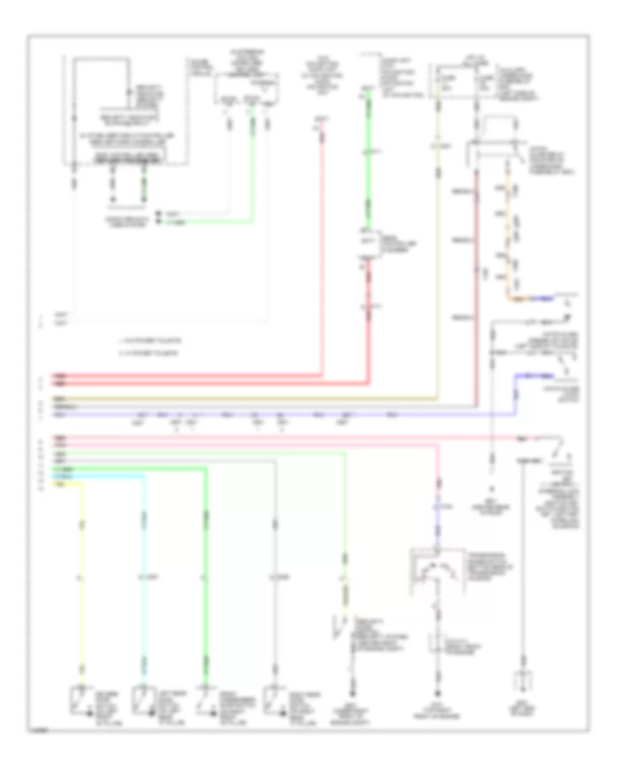
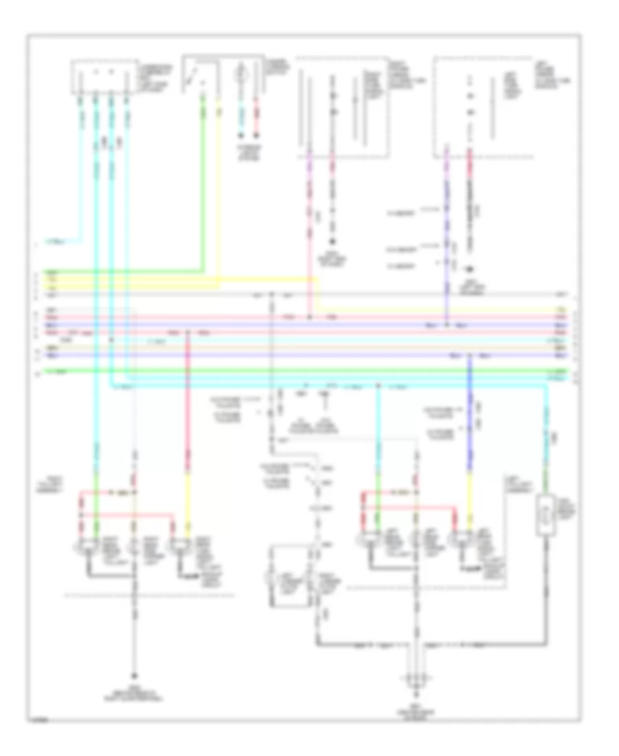
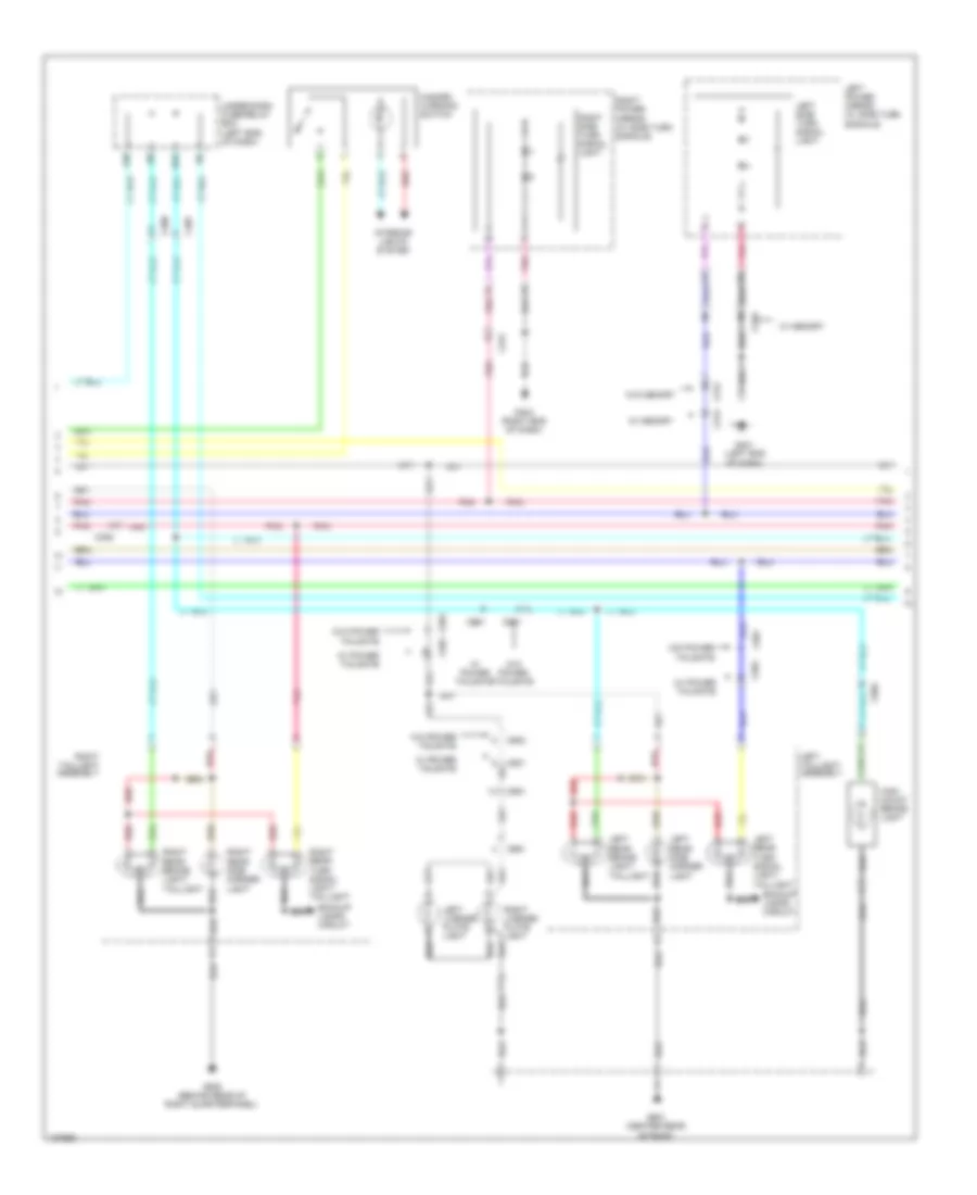
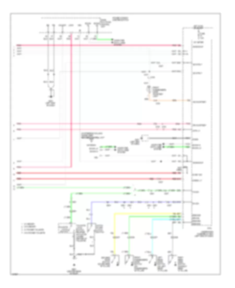
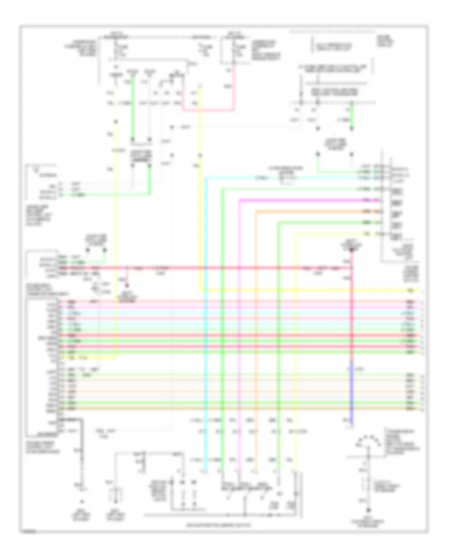
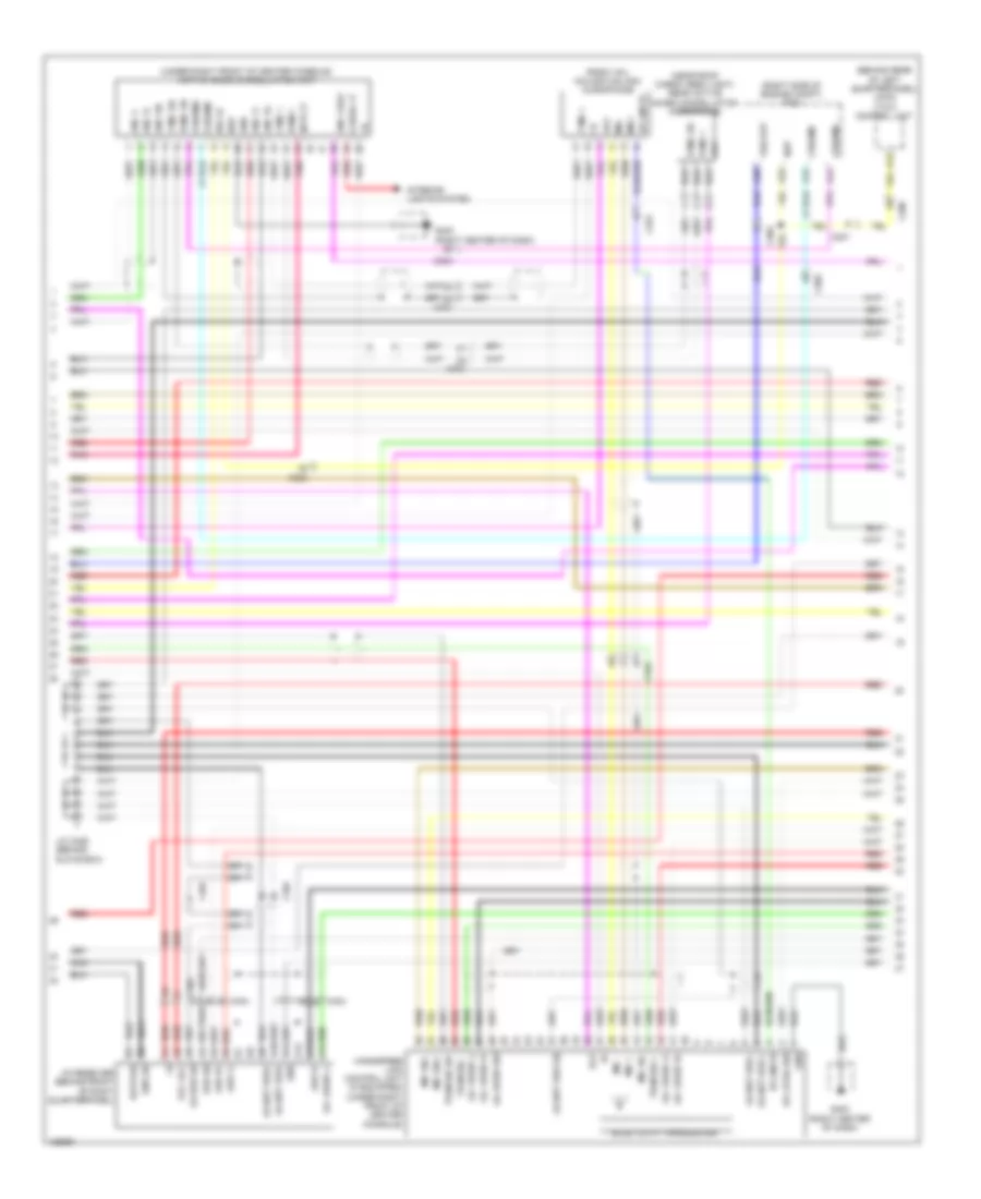
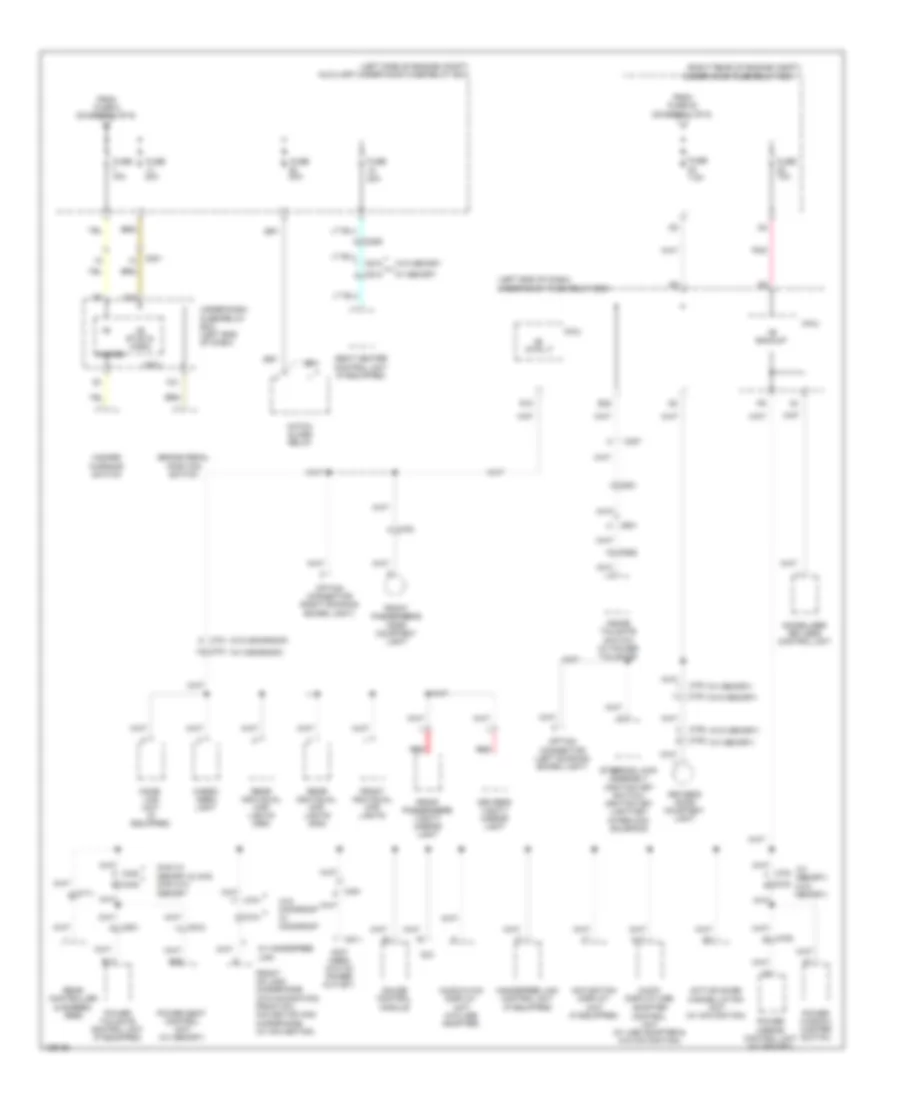
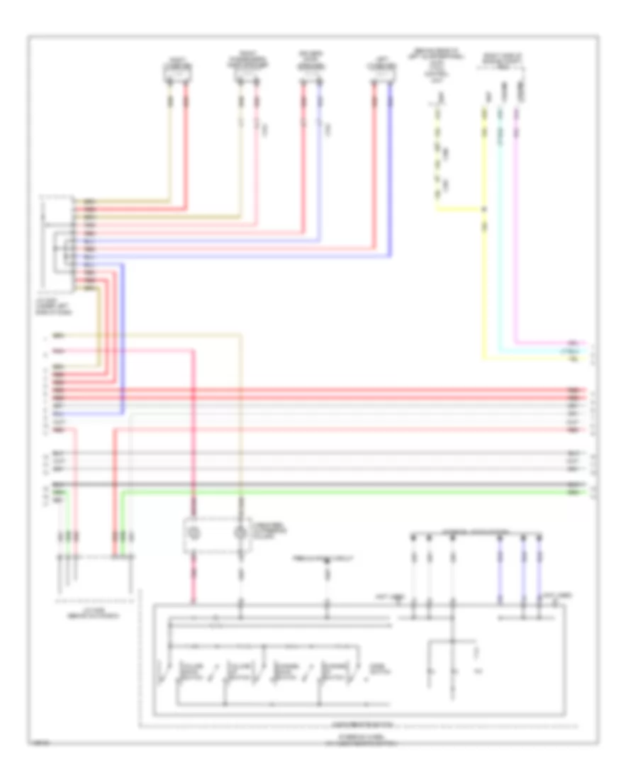
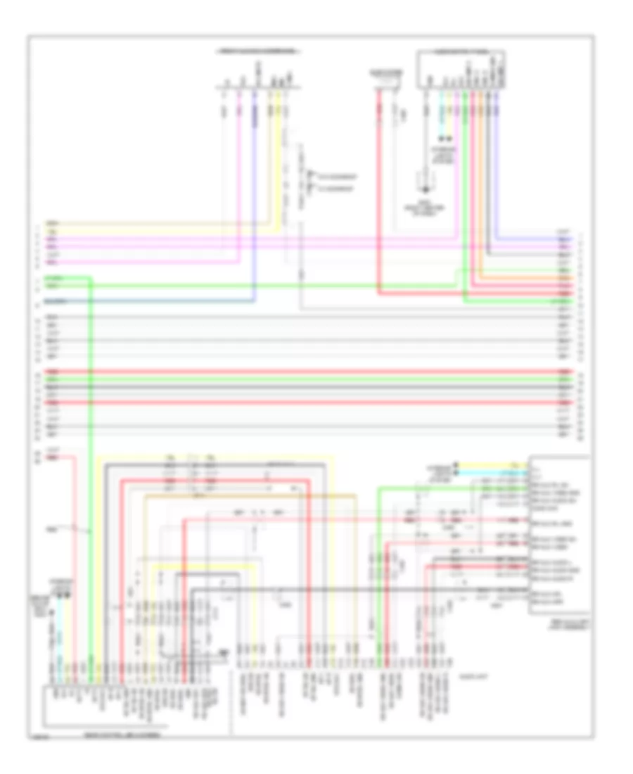
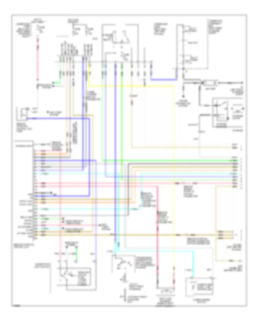
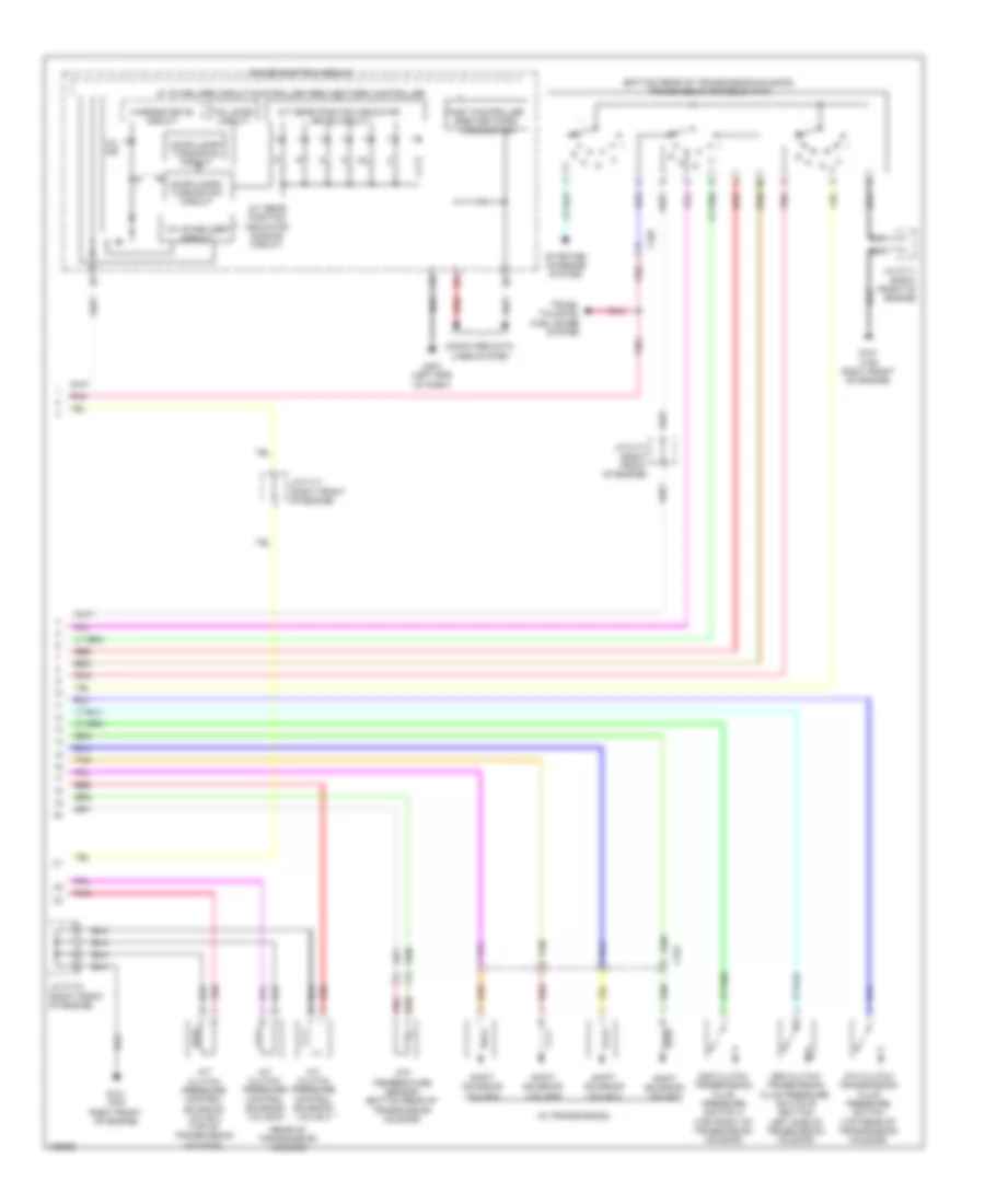
Automatic A/C Wiring Diagram (2 of 3) for Honda Pilot EX-L 2014
List of elements for Automatic A/C Wiring Diagram (2 of 3) for Honda Pilot EX-L 2014:
- (top center of dash) (w/o automatic lighting system) sunlight sensor (w/ automatic lighting system) automatic lighting/ sunlight sensor
- Amd-p
- Audio unit
- Audio-hvac display unit
- Back up
- Bus data
- C203
- C205
- C351
- C451
- C454
- C461
- C801
- Clk
- D16
- D17
- Duet 1
- Duet 2
- Duet cont
- Duet rx
- Duet sh
- Duet tx
- Front blower power transistor (on bottom of blower unit)
- Fuse 10a
- G12
- G202 (right side of engine compt)
- G403 (right center of dash)
- G801 (under left side of center console)
- Gnd
- Ground
- Hac
- Hot in on
- Humidity sensor
- Humidity/in-car temperature sensor (lower left center of dash)
- Ig2
- Ill+
- Ill-
- Illumination+
- Illumination-
- In-car temperature sensor
- Interior
- Interior lights system
- Lights system
- M-cool
- M-heat
- M-hot
- M-vent
- Micu
- Outside air temperature sensor (behind left side of front grille)
- Pnk
- Q16
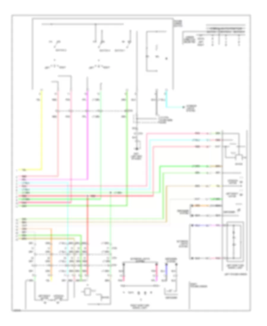
- Rear air mix control motor (on rear hvac unit)
- Rear blower motor (under center console)
- Rear blower motor relay (under left front of center console)
- Rear blower power transistor (under center console)
- Rear climate control panel
- Rear evaporator
- Rear mode control motor (on rear hvac unit)
- Red
- S-com
- S5v
- Seats system
- Sunlight sensor
- Temperature sensor (on rear hvac evaporator)
- Under-dash fuse/relay box (left end of dash)
- W/ res
- W/o res
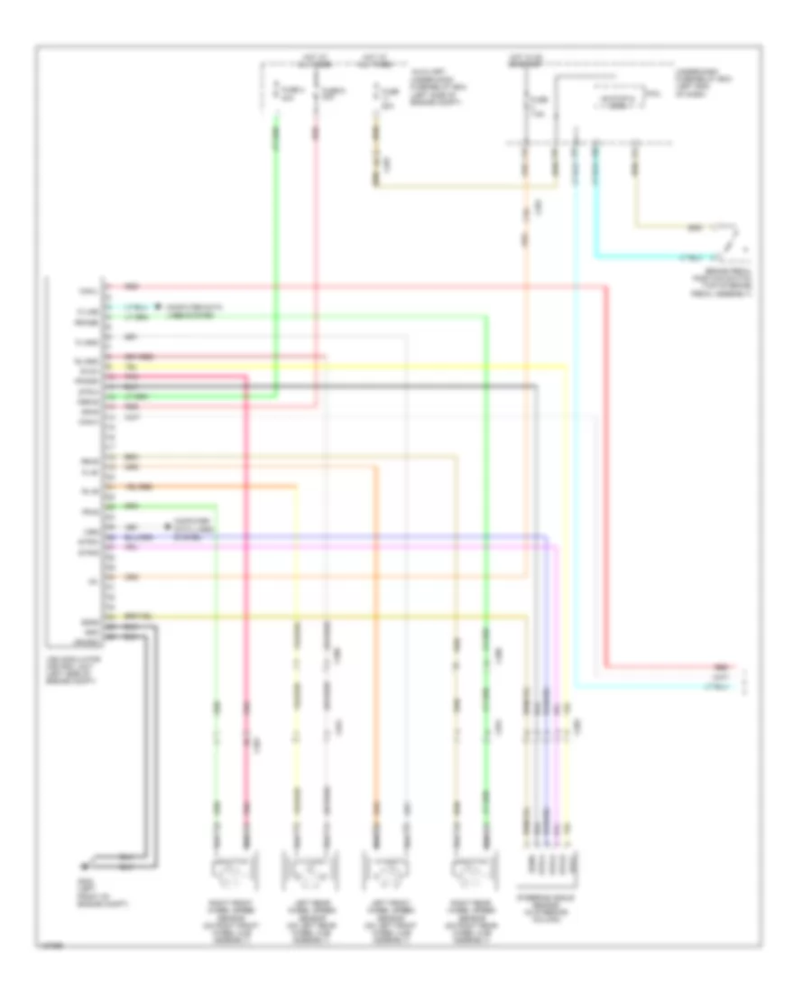
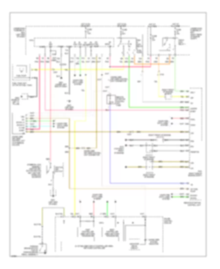
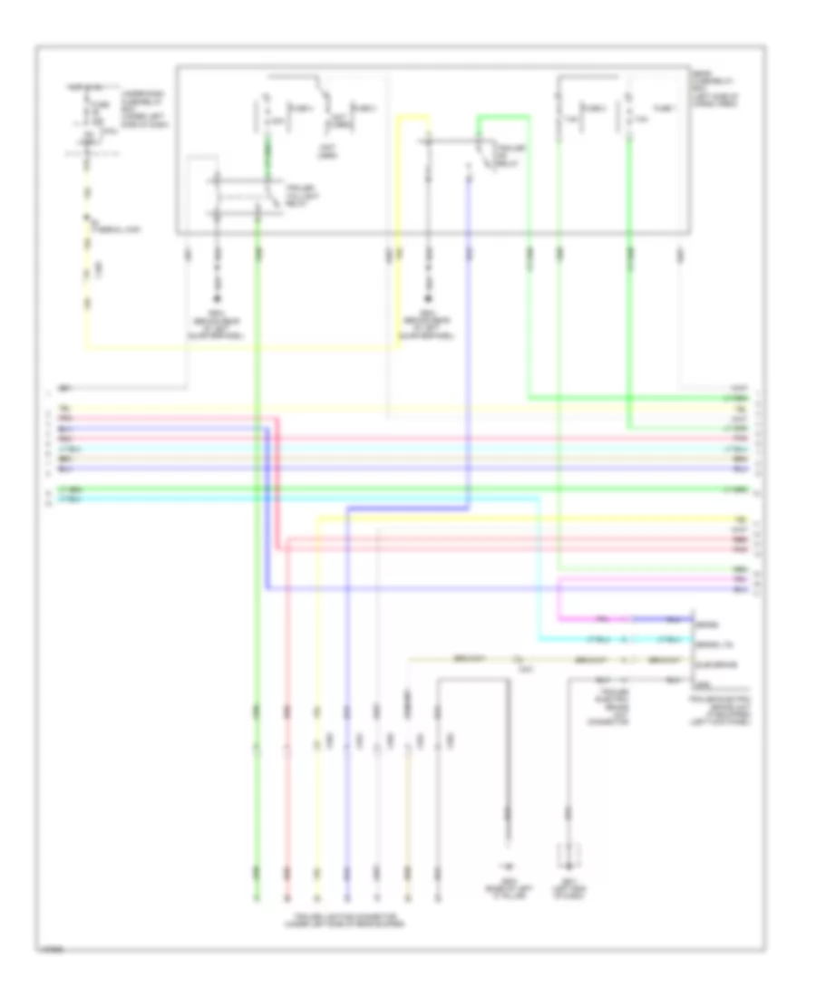
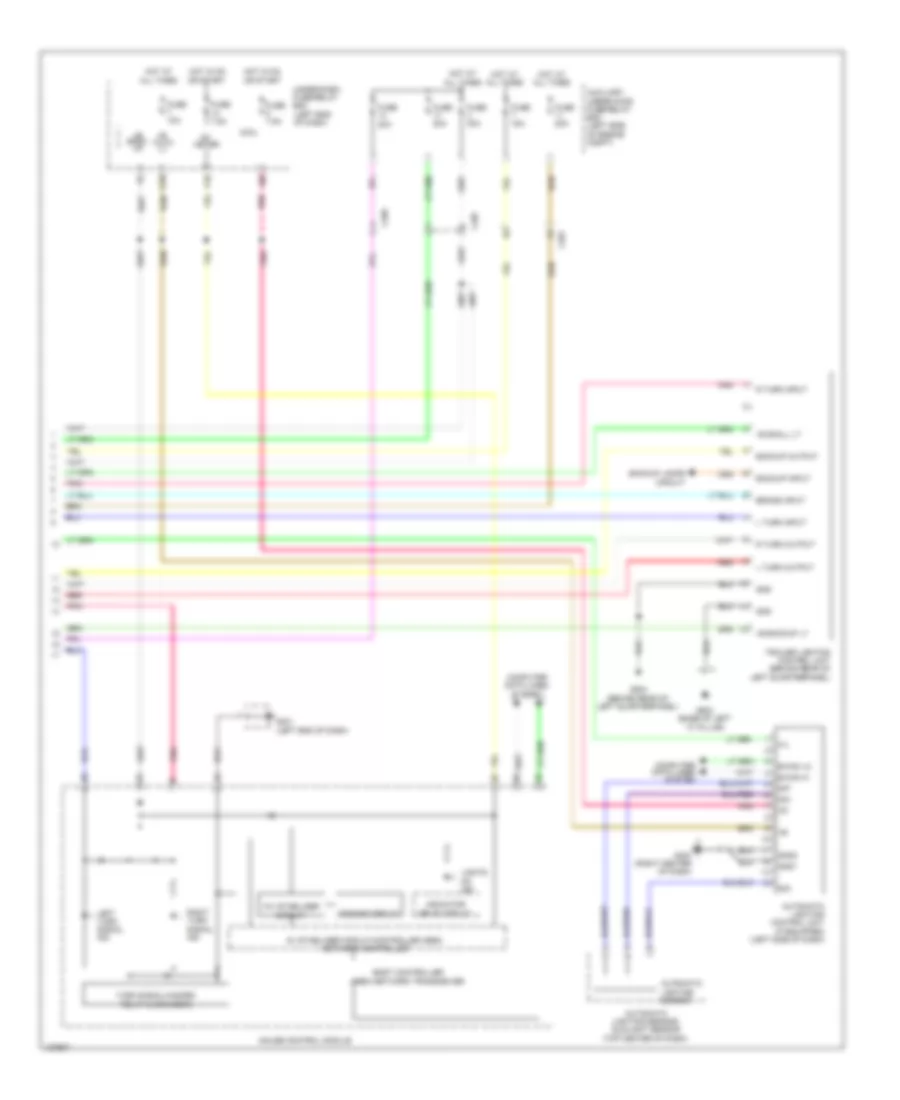
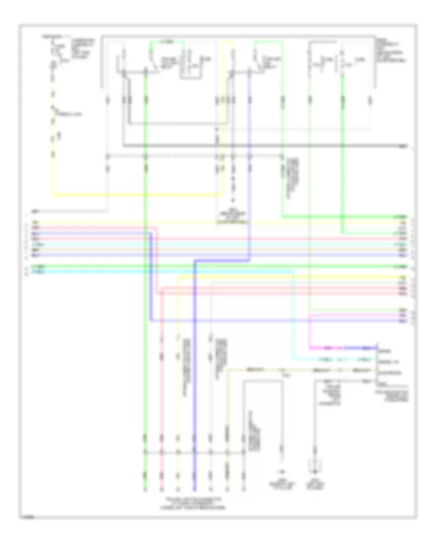
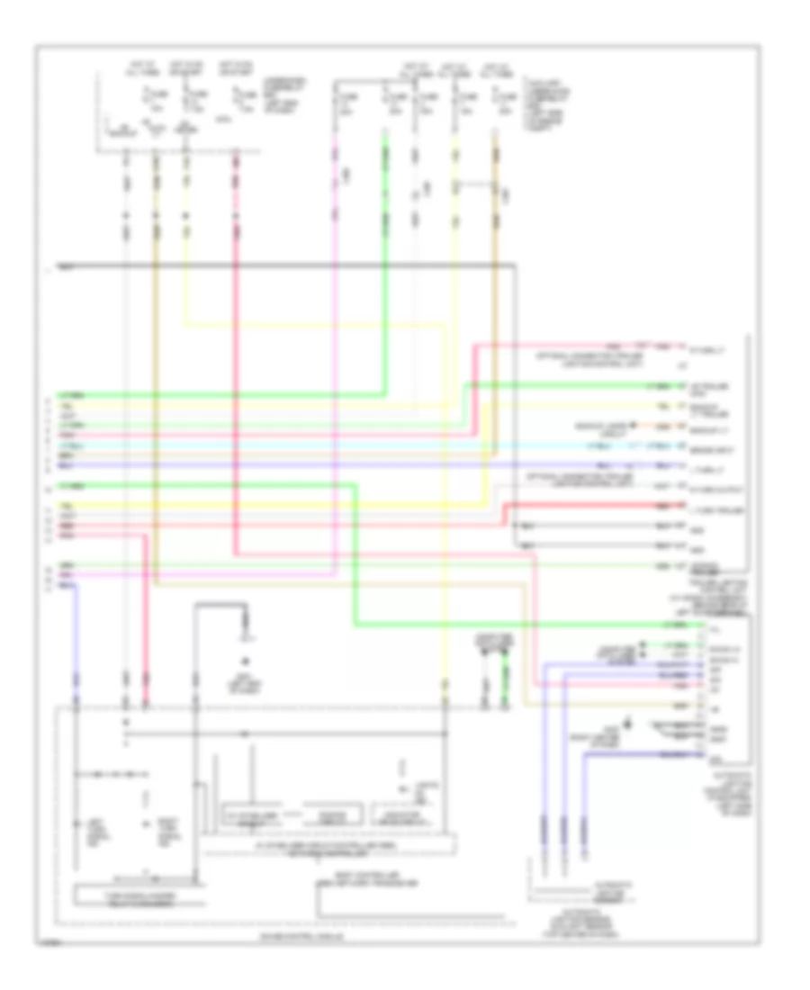
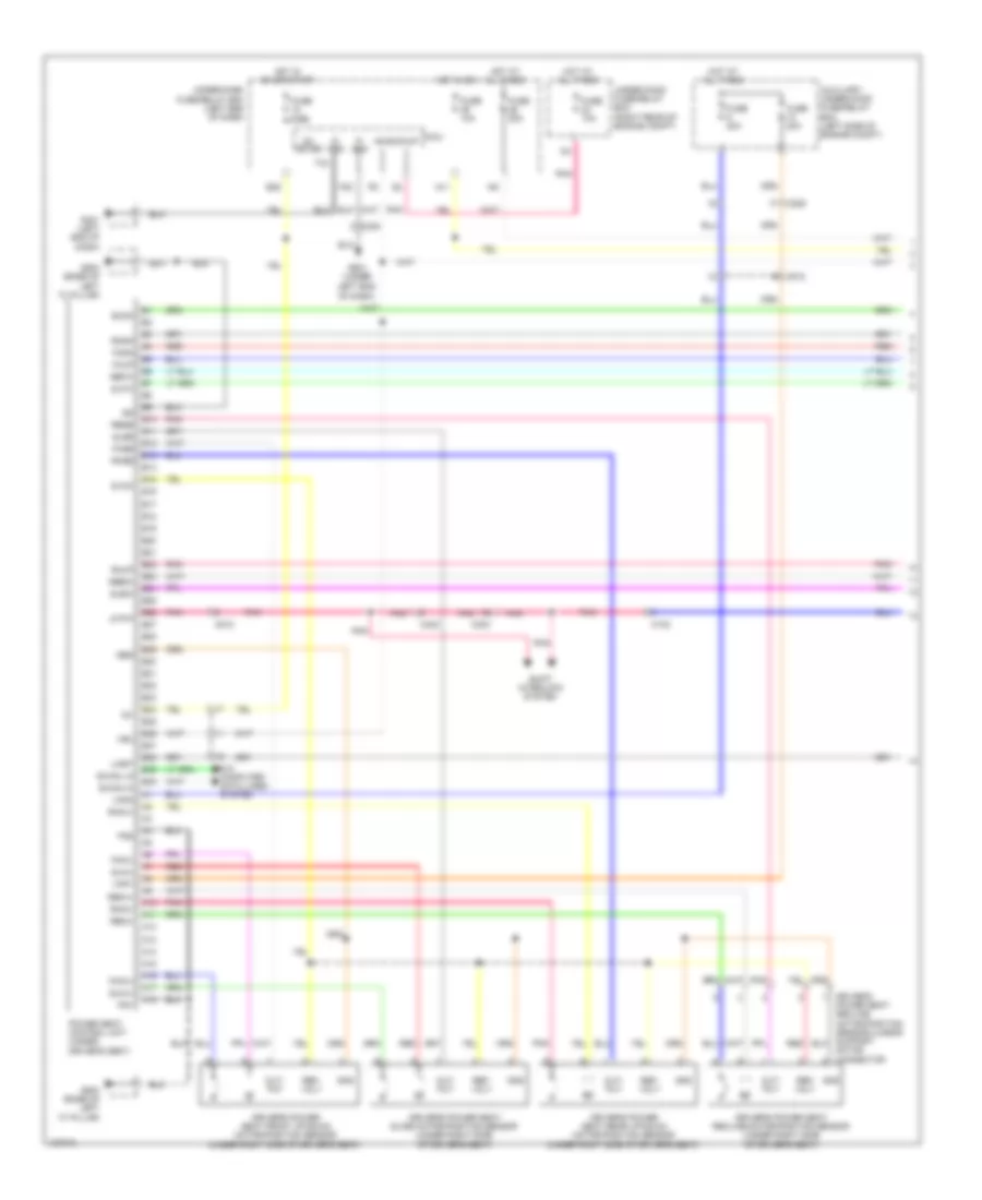
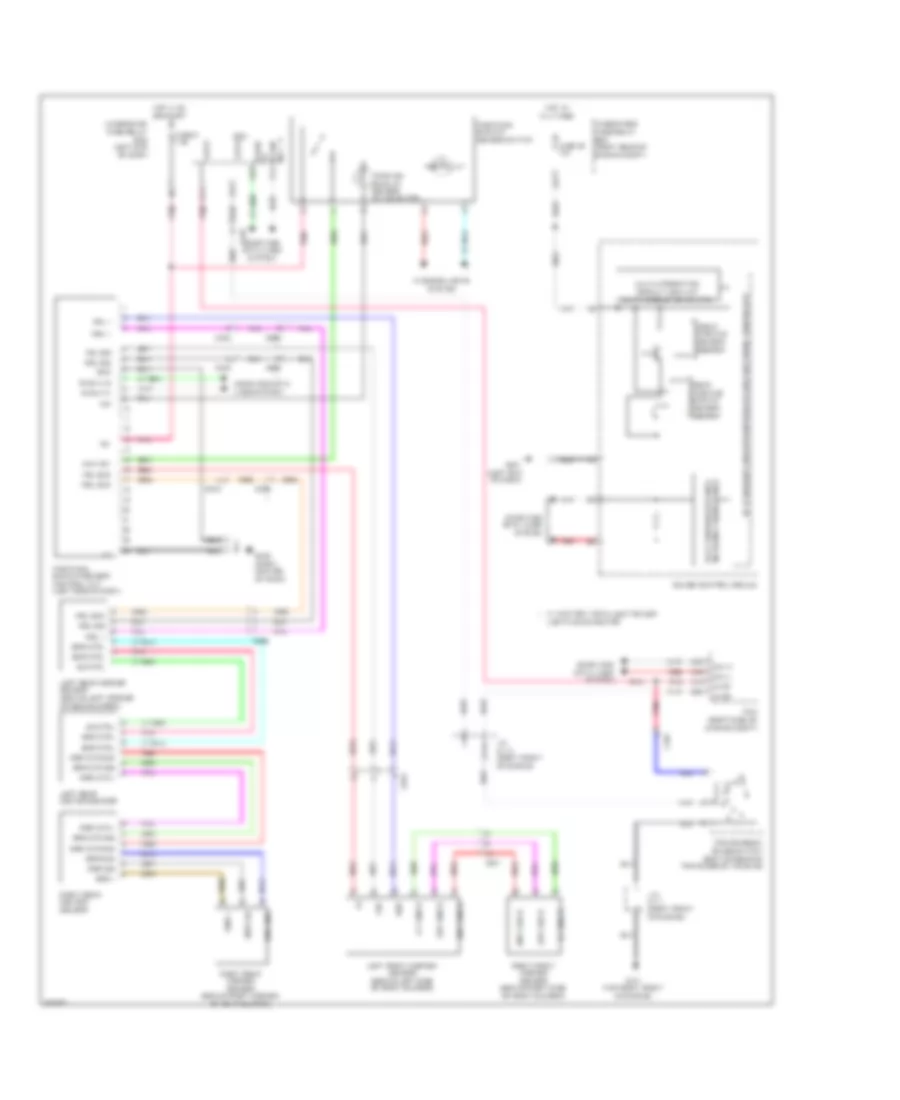
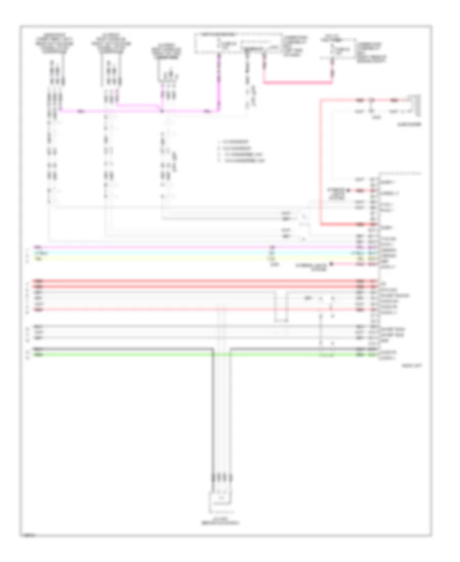
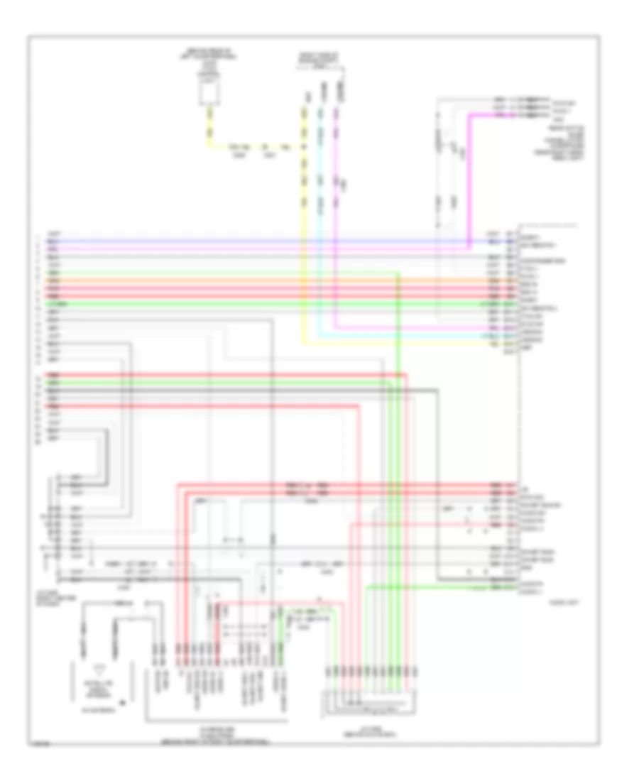
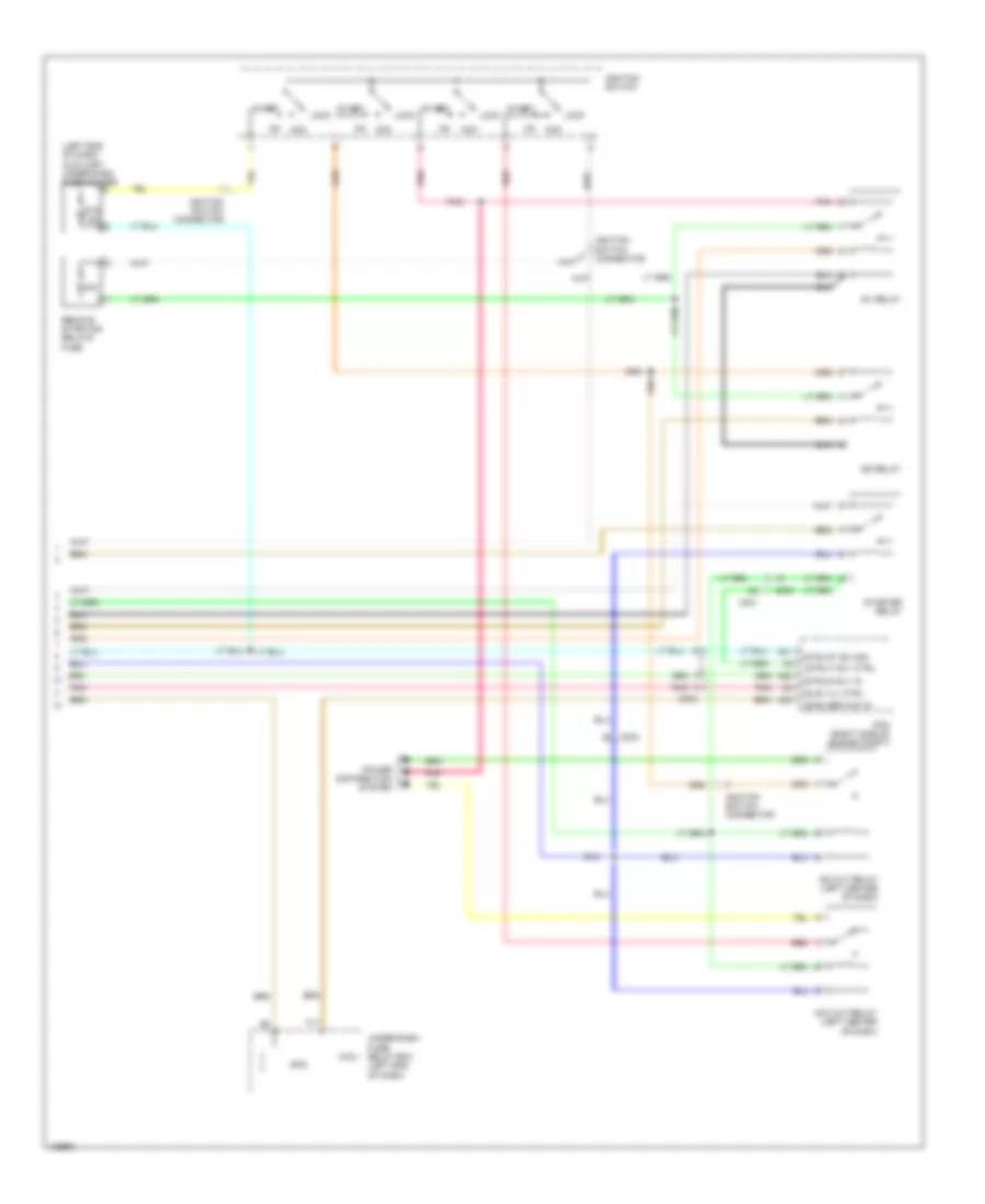
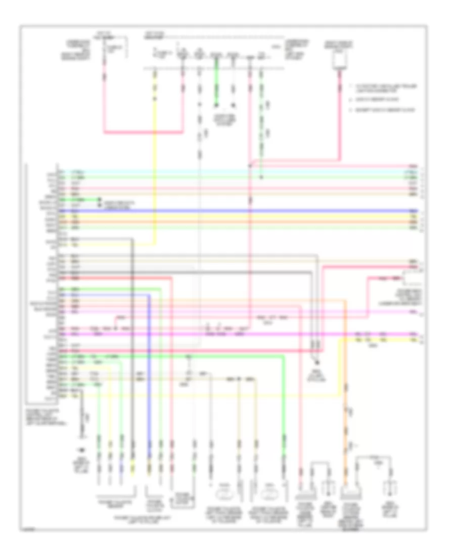
Automatic A/C Wiring Diagram (3 of 3) for Honda Pilot EX-L 2014
List of elements for Automatic A/C Wiring Diagram (3 of 3) for Honda Pilot EX-L 2014:
- (behind right kick panel) front blower motor relay
- (ect1) sens in
- (ect2) sens in
- (fan h) rly ctrl
- (fan l) rly ctrl
- (right front of engine) j/c c114
- (sg2) sens gnd
- (sg7) sens gnd
- (subrly) rly ctrl
- 40a
- A/c compressor (lower left front of engine)
- A/c compressor clutch
- A/c compressor clutch case ground
- A/c compressor clutch relay
- A/c condenser fan diode
- A/c condenser fan motor (behind right side of radiator)
- A/c condenser fan relay
- A13 (acc) rly ctrl
- A21
- A37
- A40
- A48
- A49
- C102
- C16
- C301
- C32
- C351
- Canh
- Canl
- Computer data lines system
- Ect sensor 1 (left rear of engine)
- Ect sensor 2 (lower left rear of radiator)
- Engine controls system
- F11
- F12
- F14
- F16
- F20
- Fan control relay
- Front blower motor (under right side of dash)
- Fuse 10a
- Fuse 15a
- Fuse 30a
- Fuse 7.5a
- G101 (top right front of engine)
- G201 (under right front of engine compt)
- G202 (right side of engine compt)
- Gnd
- Hot at all times
- J/c c113 (right front of engine)
- Multi-fuse 3
- Pcm (right side of engine compt)
- Pgm-fi sub relay
- Pnk
- Radiator fan diode
- Radiator fan motor (behind left side of radiator)
- Radiator fan relay
- Red
- Under-hood fuse/relay box (right rear of engine compt)
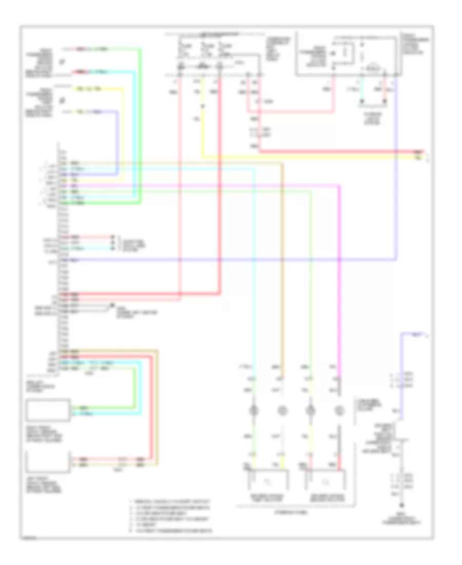
ANTI-LOCK BRAKES
Anti-lock Brakes Wiring Diagram (1 of 2) for Honda Pilot EX-L 2014
List of elements for Anti-lock Brakes Wiring Diagram (1 of 2) for Honda Pilot EX-L 2014:
- +b stop & horn
- Auxiliary
- Brake pedal position switch (top of brake pedal assembly)
- C201
- C203
- C206
- C551
- Can-h
- Can-l
- Computer data
- Computer data lines
- F16
- F25
- F30
- F31
- Fl+b
- Fl-gnd
- Fr+b
- Fr-gnd
- Fsr+b
- Fuse 20a
- Fuse 4 40a
- Fuse 6 30a
- Fuse 7.5a
- G16
- G302 (left front of engine compt)
- Gnd
- Hot at all times
- Hot in on or start
- Ig1
- K-line
- Left front wheel speed sensor (on left front wheel hub assembly)
- Left rear wheel speed sensor (on left rear wheel hub assembly)
- Lines system
- Micu
- Mr+b
- Mr-gnd
- Pnk
- Red
- Right front wheel speed sensor (on right front wheel hub assembly)
- Right rear wheel speed sensor (on right rear wheel hub assembly)
- Rl+b
- Rl-gnd
- Rr+b
- Rr-gnd
- Sgnd
- Steering angle sensor (in steering column)
- Str-a
- Str-b
- Str-d
- Svcc
- System
- Under-dash fuse/relay box (left end of dash)
- Under-hood fuse/relay box (left side of engine compt)
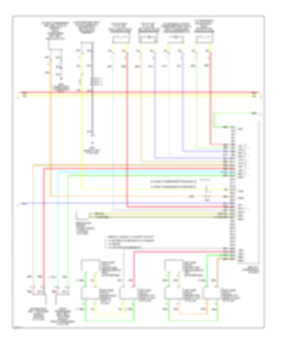
- Vsa modulator control unit (left side of engine compt)
- Wen
Anti-lock Brakes Wiring Diagram (2 of 2) for Honda Pilot EX-L 2014
List of elements for Anti-lock Brakes Wiring Diagram (2 of 2) for Honda Pilot EX-L 2014:
- (left side of engine compt) g303
- (right center
- 5v stabilizer circuit/controller area network controller
- A48
- A49
- Abs ind
- Bksw
- Brake fluid level switch (on brake fluid reservoir)
- C203
- C303
- Can-h
- Can-l
- Canh
- Canl
- Computer data lines system
- Fast controller area network transceiver
- Fuse 10a
- Fuse 7.5a
- G401 (left end of dash)
- G403
- Gauge control module
- Gnd
- Hot at all times
- Hot in on or start
- Ig1
- Indicator drive circuit
- Interior lights system
- Junction connector c421 (center of dash)
- Micu
- Of dash)
- P10
- Parking brake & brake system ind
- Parking brake switch (top of parking brake pedal assembly)
- Pcm (right side of engine compt)
- Pnk
- R18
- Red
- Under-dash fuse/relay box (left end of dash)
- Under-hood fuse/relay box (right rear of engine compt)
- Vsa off ind
- Vsa off switch
- Vsa system ind
- Yaw rate acceleration sensor (under middle of dash)
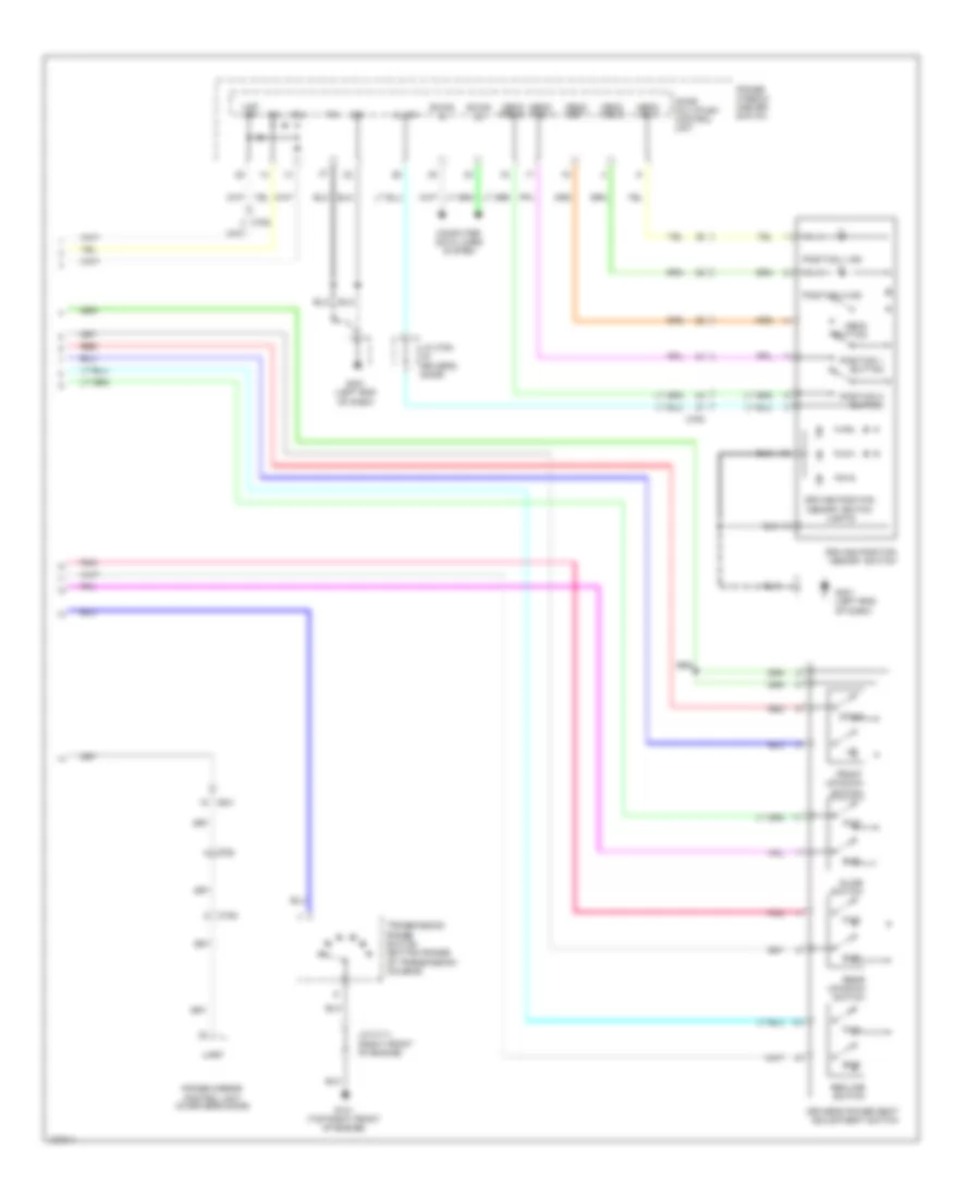
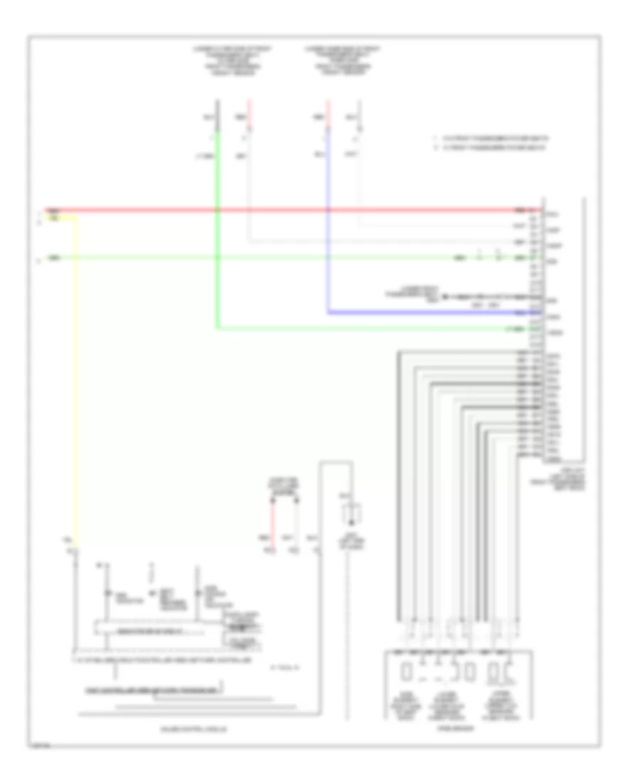
ANTI-THEFT
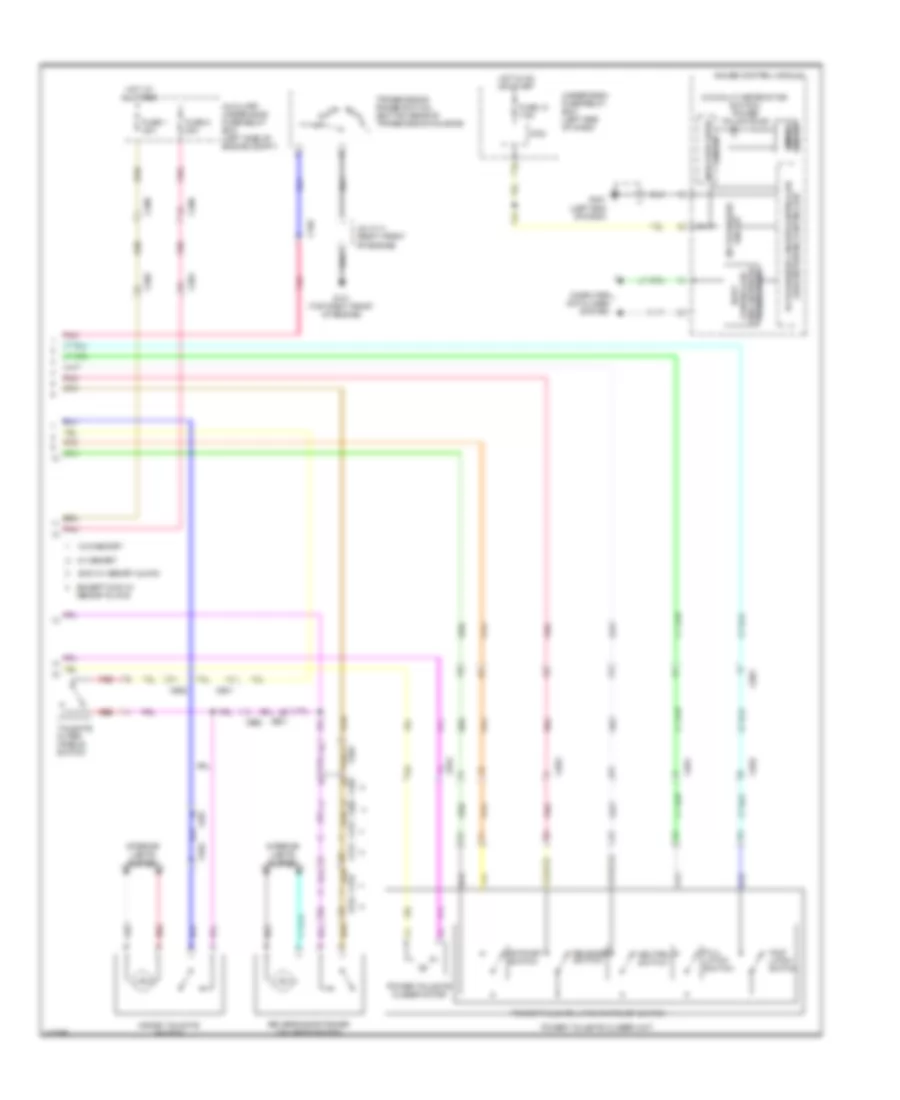
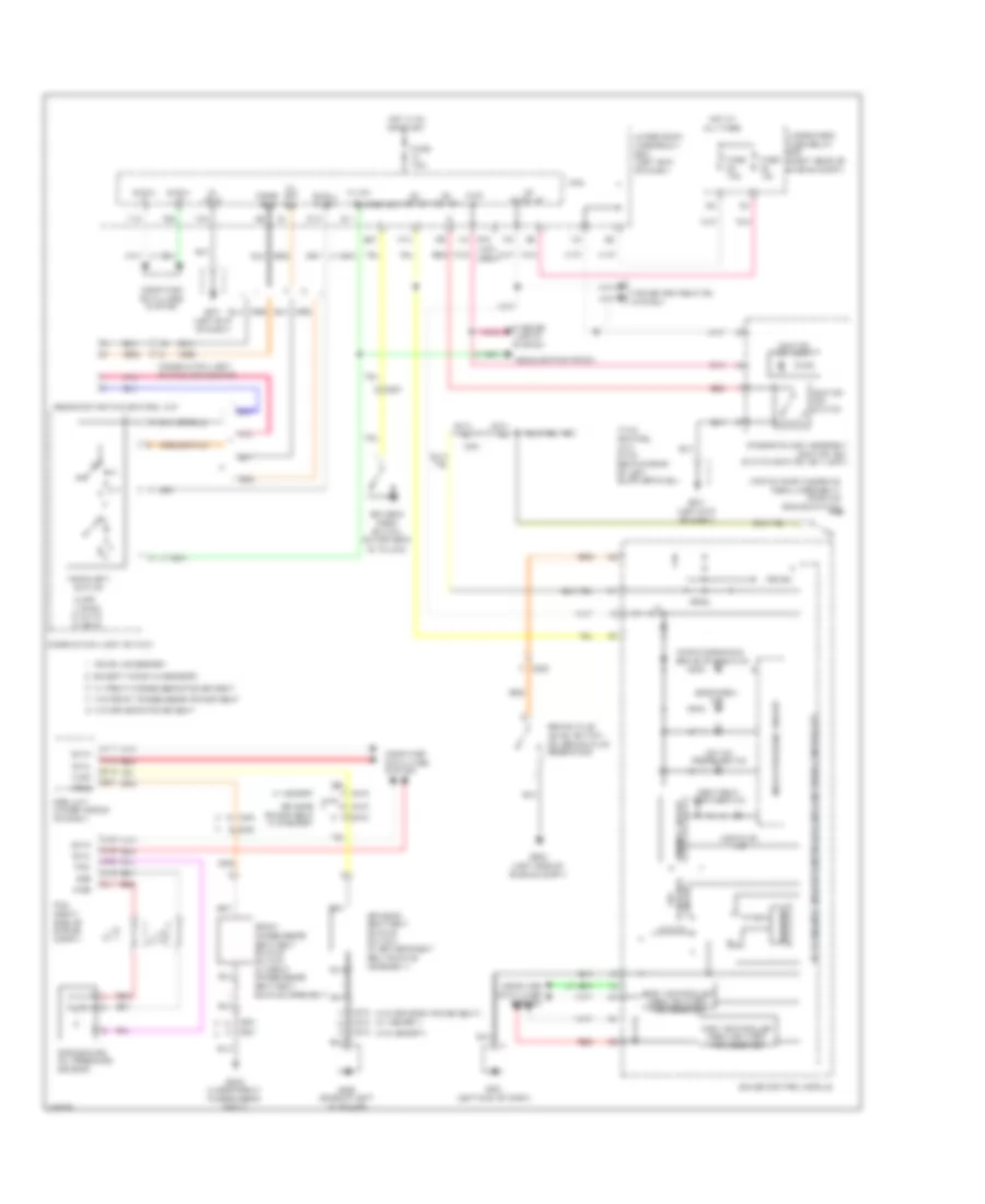
Forced Entry Wiring Diagram (1 of 3) for Honda Pilot EX-L 2014
List of elements for Forced Entry Wiring Diagram (1 of 3) for Honda Pilot EX-L 2014:
- (not c521 used)
- (not used)
- 2wd w/ memory & 4wd
- 2wd w/o memory
- Atp-p
- Audio security
- C305
- C307
- C308
- C401
- C402
- C404 c404
- C501
- C521
- C601
- C602
- C651
- C752
- C761
- C771
- C772
- C781
- C782
- Door lock relay
- Driver's door lock actuator/knob switch/ key cylinder switch
- Driver's door unlock relay
- Drswas
- Drswdr
- Drswra
- Drswrd
- E12
- E13
- E14
- E17
- E19
- E20
- E21
- E33
- E36
- E37
- Exterior lights system
- F20
- F23
- F27
- Front passenger's door lock actuator/ knob switch
- Fuse 10a
- Fuse 15a
- Fuse 20a
- Fuse 7.5a
- G/h rly
- G/h sw
- G13
- G16
- G401 (left end of dash)
- G501 (under left end of dash)
- G502 (under front passenger's seat)
- G503 (base of left "c" pillar)
- G601 (center rear of roof)
- Headlight low beam relay
- Headlights system
- Hood sw
- Horn relay
- Hot at all times
- Hot in on or start
- Ig key sw
- Ig1 meter
- Left rear door lock actuator/ knob switch
- Left rear door lock knob switch
- Lock
- M10
- Micu
- N13
- P-gnd
- Passenger's door unlock relay
- Pnk
- R15
- R16
- Red
- Res
- Right rear door lock actuator/ knob switch
- Right rear door lock actuator/knob switch
- Right rear door lock knob switch
- Rl dl sil sw
- Rr dl sil sw
- S-gnd
- Scty (micu)
- T/g handle sw
- T/g sw
- T25
- T26
- T34
- Tailgate latch switch
- Tailgate latch switch/ release actuator (lower center of tailgate)
- Tailgate latch switch/ release actuator diode (w/o power tailgate) (tailgate latch switch: lower center of tailgate)
- Tailgate outer handle switch
- Tailgate release actuator
- Tailgate unlock relay (w/o power tailgate)
- Taillight relay
- Under-dash fuse/relay box (left end of dash)
- Unlock
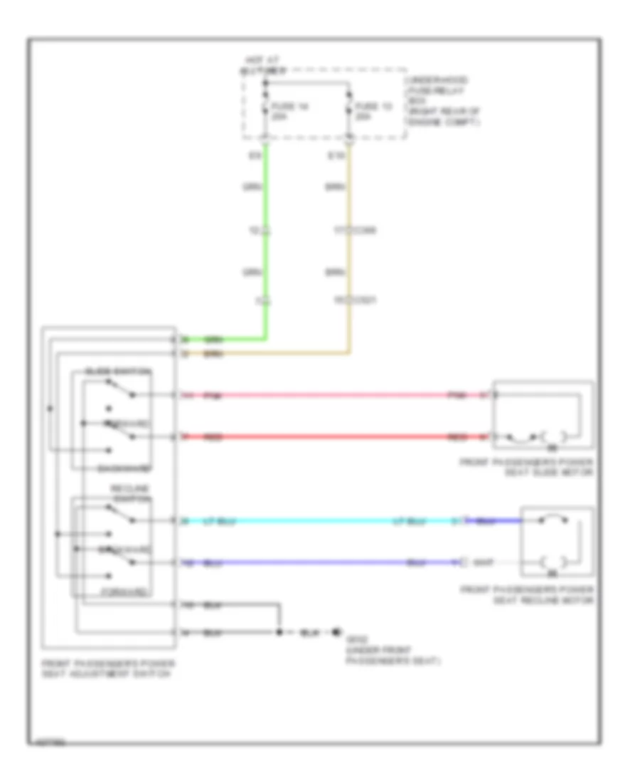
- W/ front passenger's power seat
- W/ xm radio
- W/o front passenger's power seat
- W/o power tailgate
- W/o res
- W/o xm radio
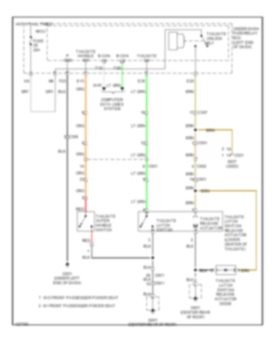
Forced Entry Wiring Diagram (2 of 3) for Honda Pilot EX-L 2014
List of elements for Forced Entry Wiring Diagram (2 of 3) for Honda Pilot EX-L 2014:
- (in driver's door) j/c c754
- +b back up
- B- can hi
- B- can lo
- B-can hi
- B-can lo
- C11
- C307
- C501
- C601
- C651
- C652
- C751
- C752
- C761
- Computer data
- Control unit
- Door lock knob
- Door lock switch
- Door lock switch lock light
- Door lock switch unlock light
- Door multiplex control unit
- Driver's door key cylinder switch
- Driver's door lock actuator/knob switch/ key cylinder switch
- Driver's door lock knob switch
- Front passenger's door lock actuator/knob switch
- Front passenger's door lock knob switch
- Front passenger's power window switch
- Fuel doors system
- Full
- Full latch switch
- Fuse 10a
- Fuse 20a
- G401 (left end of dash)
- G404 (right end of dash)
- High horn (behind right side of front bumper)
- Hot at all times
- Hot in on
- Ig2
- Key
- Knob lock
- Knob un lock
- Knob unlock
- Lines system
- Lock
- Low horn (behind right end of front bumper)
- Micu
- N11
- Ohsw
- Pnk
- Power tailgate closer unit (w/ power tailgate)
- Power tailgate control unit (w/ power tailgate) (behind rear of left quarterpanel)
- Power tailgate latch/ratchet switch
- Power tops system
- Power window master switch
- Red
- Scom
- Seg3
- T/g sw
- T12
- T29
- Tailgate outer handle switch (w/ power tailgate)
- Trunk, tailgate &
- Uart
- Un lock
- Under-dash fuse/relay box (left end of dash)
- Under-hood fuse/relay box (right rear of engine compt)
- Unlock
- Vbu
- Vmp as
- Vmp dr
- W/ power tailgate
- W/o memory w/ memory
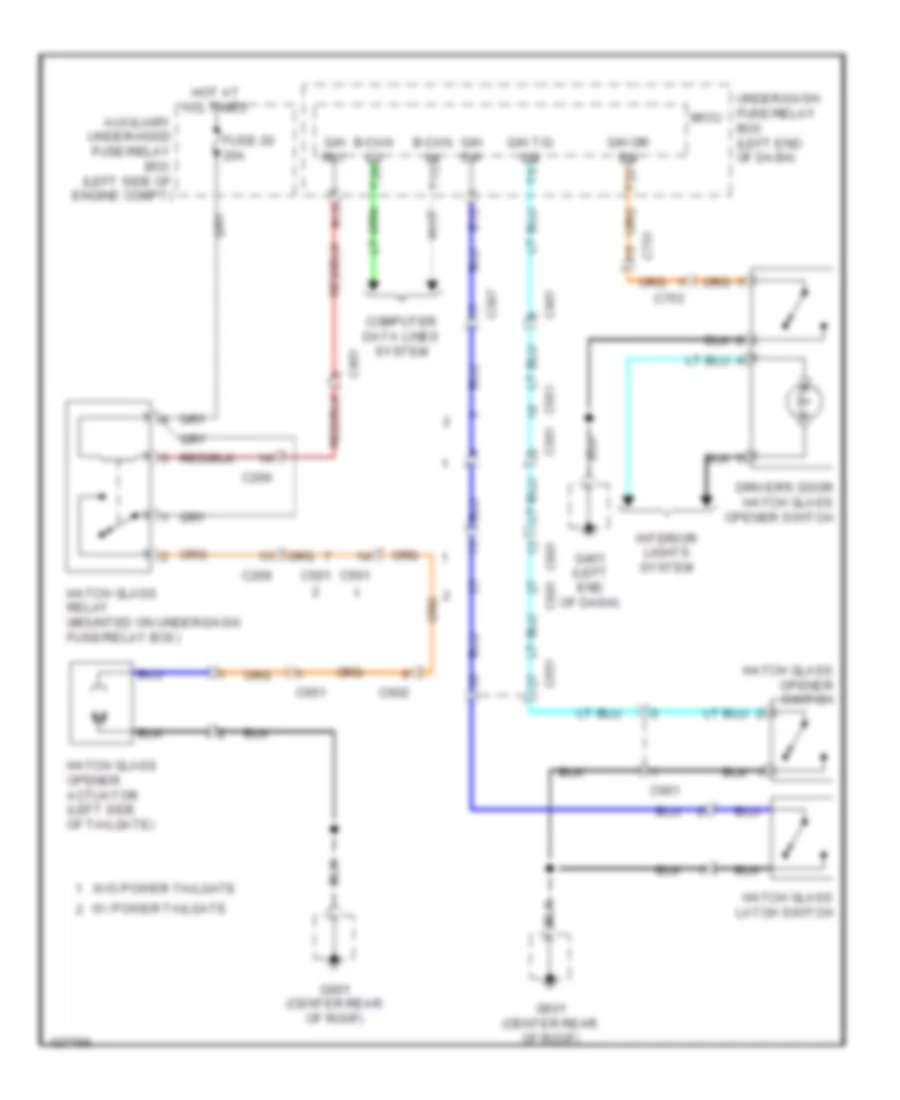
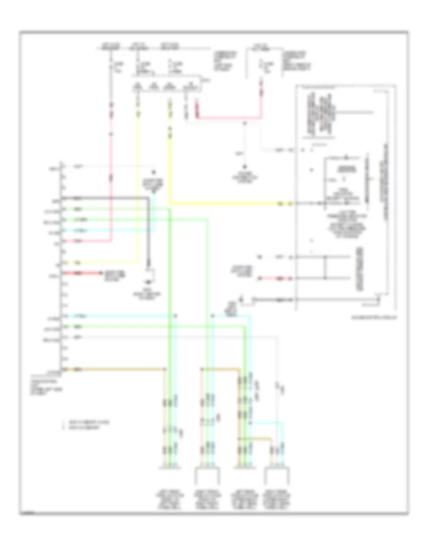
Forced Entry Wiring Diagram (3 of 3) for Honda Pilot EX-L 2014
List of elements for Forced Entry Wiring Diagram (3 of 3) for Honda Pilot EX-L 2014:
- (in steering column) immobilizer- keyless control unit
- (w/o navigation) audio unit (w/ navigation) audio navigation unit
- 5v stabilizer circuit/controller area network controller
- Antenna
- Audio unit (w/o navigation) audio navigation unit (w/ navigation)
- Auxiliary under-hood fuse/relay box (left side of engine compt)
- B-can hi
- B-can lo
- Body controller area network transceiver
- C102
- C201
- C206
- C306
- C307
- C401
- C501
- C601
- C602
- C651
- C711
- C711 red
- Computer data
- Driver's door switch (on left front "b" pillar)
- Front passenger's door switch (on right front "b" pillar)
- Fuse 20a
- G101 (top right front of engine)
- G201 (under right front of engine compt)
- G401 (left end of dash)
- G601 (center rear of roof)
- Gauge control module
- Hatch glass latch switch
- Hatch glass opener actuator (left side of tailgate)
- Hatch glass relay (mounted on under-dash fuse/relay box)
- Hot at all times
- Ignition key switch
- J/c c111 (right front of engine)
- Left rear door switch (on left rear "c" pillar)
- Lines system
- Pnk
- Rear controller & screen
- Red
- Right rear door switch (on right rear "c" pillar)
- Scty
- Security hood switch (security system) (center front of engine compt)
- Security indicator (security system)
- Security indicator blinking circuit
- Steering lock assembly (ignition key switch/ignition key light/key interlock solenoid)
- Transmission range switch (bottom rear of transmission housing)
- Vbu
- W/ power tailgate
- W/o power tailgate
Immobilizer Wiring Diagram for Honda Pilot EX-L 2014
List of elements for Immobilizer Wiring Diagram for Honda Pilot EX-L 2014:
- (not
- (right front of engine)
- (right front of engine) j/c c111
- (right front of engine) j/c c113
- +b back
- 5v stabilizer circuit/controller area network controller
- A11
- A41
- A46
- A48
- A49
- B- can
- B-can hi
- B-can lo
- B-canh
- B-canl
- B40
- B41
- B42
- Back
- Body controller area network transceiver
- C102
- C303
- C307
- C308
- C41
- Canh
- Canl
- Computer data lines system
- F10
- F20
- F24
- Fast controller area network transceiver
- Fuel pump
- Fuel tank unit (in top of fuel tank)
- Fuse 10a
- Fuse 15a
- Fuse 20a
- Fuse 7.5a
- G101 (top right front of engine)
- G401 (left end of dash)
- G501 (under left end of dash)
- G503 (base of left "c" pillar)
- Gauge control module
- Hot at all times
- Hot in on or start
- Ig key
- Ig1
- Ig1 fuel
- Ig1 fuel pump
- Ignition key switch
- Igp
- Immobilizer keyless control unit (in steering column)
- Immobilizer keyless control unit connector
- Immobilizer system indicator
- Imofpr
- Indicator drive circuit
- J/c c111 (right front of engine)
- J/c c112
- K-line
- Lg1
- Lg2
- Lg3
- Meter
- Micu
- Mrly
- P-gnd
- P10
- Parking brake switch (top of parking brake pedal assembly)
- Pcm (right side of engine compt)
- Pg1
- Pg2
- Pgm- fi main relay (fuel pump)
- Pgm-fi main relay 1
- Pgmetcs
- Pnk
- Pump
- R12
- R16
- Red
- Remote starting control unit
- Remote starting control unit fuse
- S-gnd
- S-net
- Steering lock assembly (ignition key switch/ignition key light/key interlock solenoid)
- T12
- T29
- T34
- Under-dash fuse/relay box (left end of dash)
- Under-hood fuse/relay box (right rear of engine compt)
- Used)
- Vbu
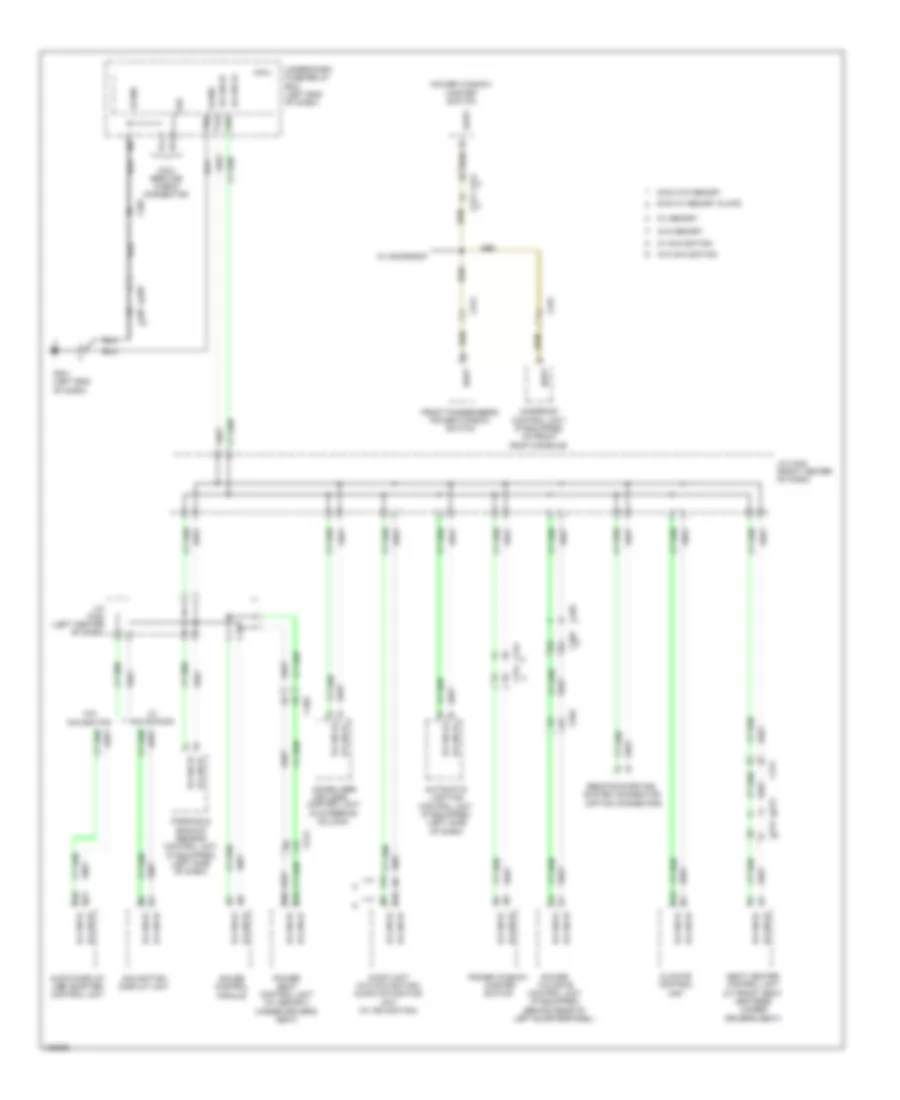
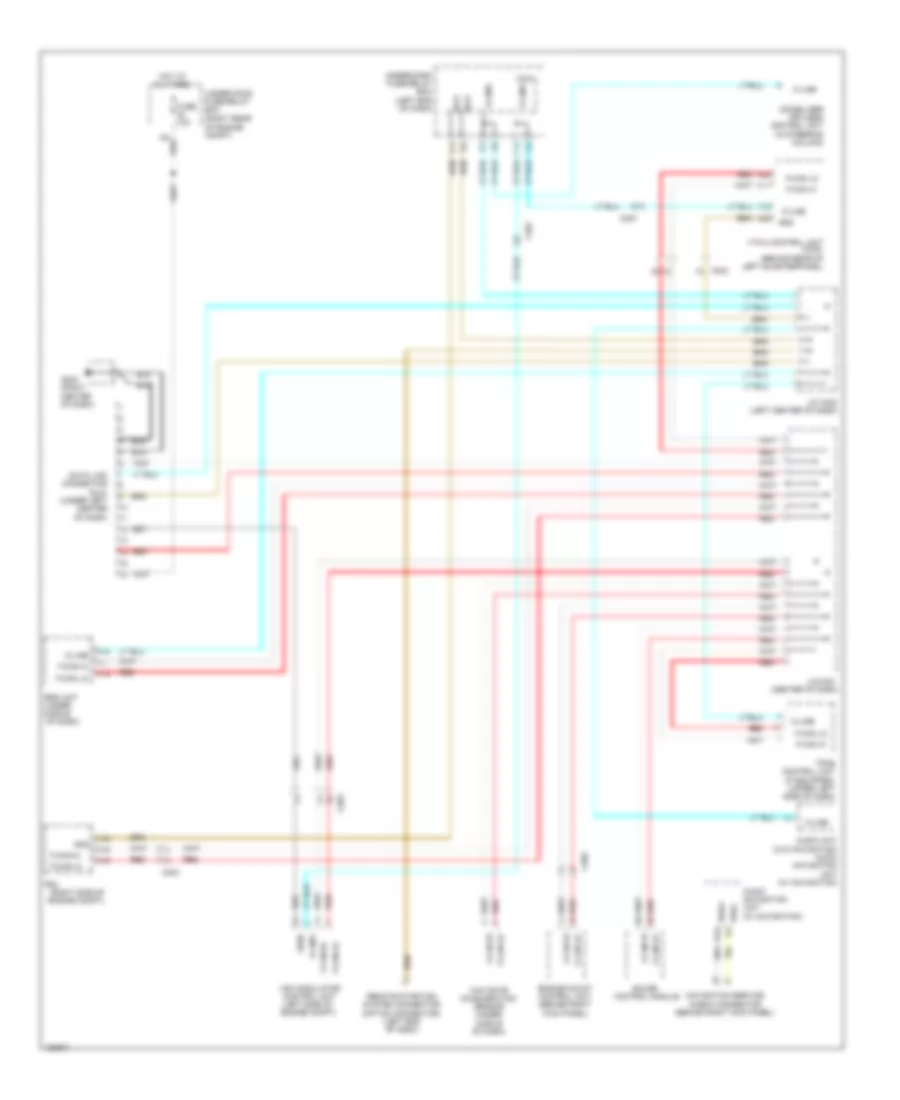
BODY CONTROL MODULES
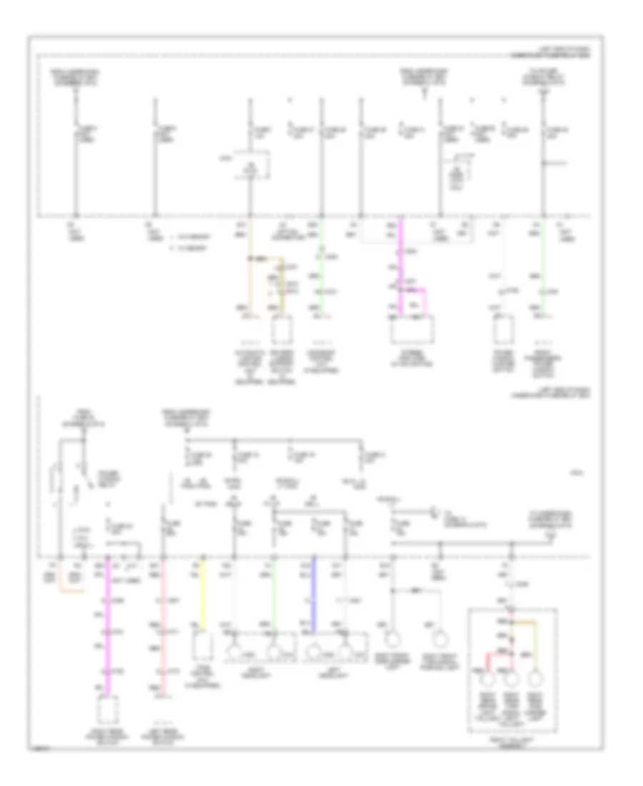
Body Control Modules Wiring Diagram (1 of 2) for Honda Pilot EX-L 2014
List of elements for Body Control Modules Wiring Diagram (1 of 2) for Honda Pilot EX-L 2014:
- (4wd)
- (not used)
- (option connector)
- +b auto lt
- +b backup
- +b d/l
- +b door lock
- +b drl main
- +b h/l lo main
- +b haz
- +b intr lt
- +b small
- +b small lt
- +b stop & horn
- +b tpms
- 2wd w/ memory & 4wd
- 2wd w/o memory
- Acc
- Acc key lock
- Air conditioning, exterior lights & seats systems
- Anti-lock brakes system
- Anti-theft & starting/charging systems
- Anti-theft system
- Atp-p
- Atp-r
- Back lt-
- C307
- C308
- C402
- Cruise control system
- E15
- E25
- E26
- E33
- E34
- Engine controls system
- Exterior & interior lights systems
- Exterior lights & seats systems
- Exterior lights system
- Exterior, mirrors & navigation systems
- F18
- F19
- F20
- F25
- F27
- F30
- F31
- F32
- F33
- F34
- Fr wiper (as)
- Fr wiper (hi)
- Fr wiper (lo)
- Fr wiper mtr
- Fuse (not used)
- Fuse 10a
- Fuse 15a
- Fuse 20a
- Fuse 30a
- Fuse 7.5a
- G16
- G401 (left end of dash)
- G501 (under left end of dash)
- Hot at all times
- Hot in acc or on
- Hot in on
- Hot in on or start
- Ig1 fuel pump
- Ig1 meter
- Ig1 ods
- Ig1 srs
- Ig1 vsa
- Ig1 vtm 4
- Ig1 vtm-4
- Ig1 wiper
- Ig2 daylight
- Ig2 hac
- Ill+
- Ill-
- Instrument cluster, transmission & memory systems
- Int lt-
- Interior lights & sound systems
- Interior lights system
- Interior lights, navigation & sound systems
- Micu
- Micu chk
- Micu service check connector
- P-gnd
- P/w rly
- P10
- Pnk
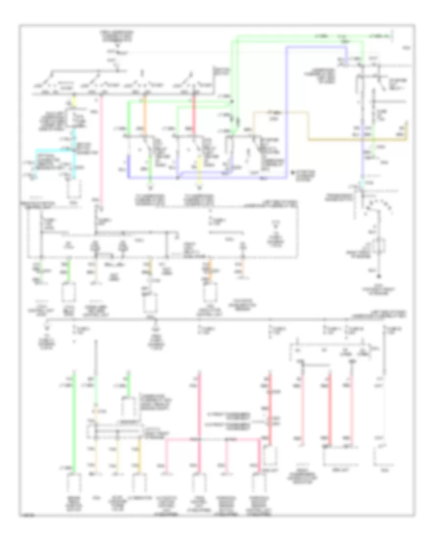
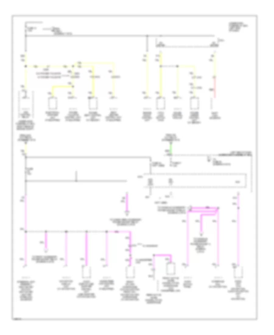
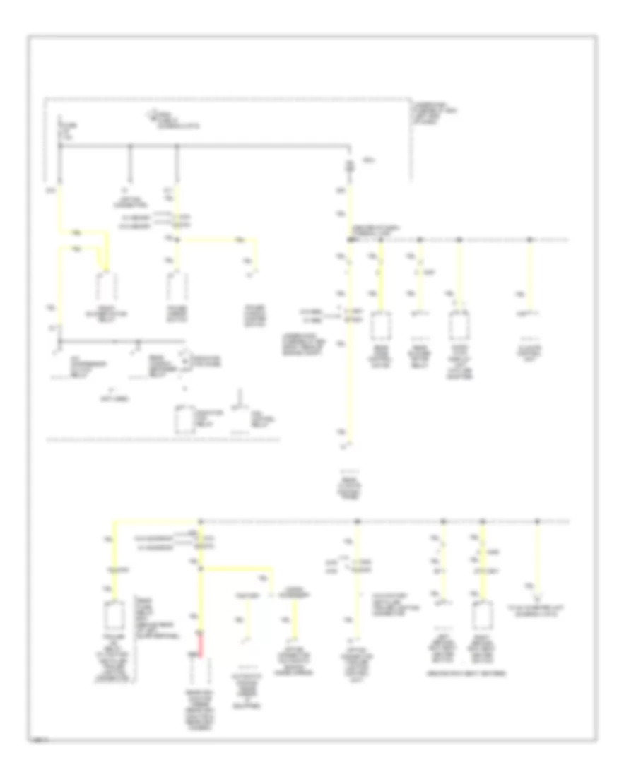
- Power distribution system
- Power windows system
- Power windows, memory, computer data lines, instrument cluster, trunk, tailgate, fuel doors, sound & navigation systems
- Q10
- Q12
- Q13
- Q14
- Q16
- R10
- R11
- R12
- R17
- R18
- R19
- R20
- Red
- Rr washer mtr
- S-gnd
- Shift interlock system
- Small rly-
- Stop sw
- Transmission system
- Transmissions system
- Under-dash fuse/relay box (left end of dash)
- Vsa
- Wiper/ washer system
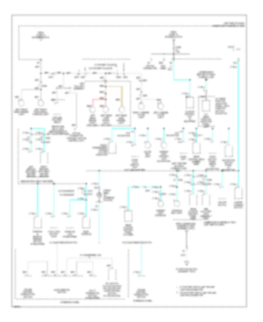
Body Control Modules Wiring Diagram (2 of 2) for Honda Pilot EX-L 2014
List of elements for Body Control Modules Wiring Diagram (2 of 2) for Honda Pilot EX-L 2014:
- (not used)
- (not used) g5
- +b drl-l
- +b drl-r
- +b h/l lo
- +b small lt
- +b tpms
- Anti-theft system
- As courtesy
- Auxiliary under-hood fuse/relay box (left side of engine compt)
- B-can hi
- B-can lo
- C201
- Cargo lt
- Combi gnd (light)
- Combi gnd wiper
- Computer data lines system
- Dimmer sw
- Door locks & interior lights systems
- Door locks system
- Dr courtesy
- Dr lock rly
- Dr-lock rly
- Drswas
- Drswdr
- Drswra
- Drswrd
- E12
- E13
- E14
- E16
- E17
- E19
- E20
- E21
- E36
- E37
- E40
- Exterior lights & headlights systems
- Exterior lights system
- F11
- F14
- F22
- F23
- F28
- Fog rly
- Fr fog sw
- Fr wash sw
- Fr wiper high & low sw
- Fr wiper int & low
- Fr wiper int vr+
- Fr wiper mist sw
- Fuse 10a
- Fuse 15a
- Fuse 20a
- Fuse 7.5a
- G/h dr sw
- G/h rly
- G/h sw
- G/h t/g sw
- G13
- G15
- G17
- G401 (left end of dash)
- H/l off sw
- H/l on sw
- Handle sw
- Hazard sw
- Headlights & exterior lights systems
- Headlights system
- Hood sw
- Horn rly
- Horns system
- Hot at all times
- Ig key sw
- Interior lights system
- K-line
- Key lock sol
- M10
- Micu
- N13
- P-pin sw
- Pass dr rly
- Passing sw
- Pnk
- Q11
- R14
- R15
- R16
- Red
- Rl dl sil sw
- Rr dl sil sw
- Rr washer sw
- Rr wip rs
- Rr wip rwd
- Rr wiper as
- Rr wiper fwd
- Rr wiper sw
- S-gnd
- S-net
- S10
- S11
- S12
- S13
- S14
- S15
- S16
- S17
- S18
- S19
- S20
- Scs
- Scty
- Shift interlock system
- Small lt sw
- Sound systems
- T/g sw
- T10
- T11
- T12
- T13
- T14
- T15
- T16
- T17
- T18
- T19
- T20
- T21
- T22
- T23
- T24
- T25
- T26
- T27
- T28
- T29
- T30
- T31
- T32
- T33
- T34
- Trn sig/haz flshr ct
- Trunk, tailgate, fuel door system
- Trunk, tailgate, fuel doors system
- Turn sw l
- Turn sw r
- Ulck rly
- Under-dash fuse/relay box (left end of dash)
- Under-hood fuse/relay box (right rear of engine compt)
- Warning & interior lights systems
- Warning systems
- Wiper/washer system
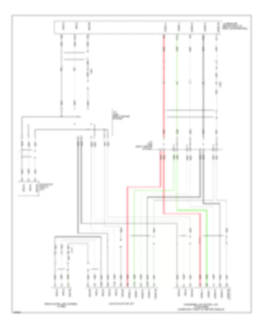
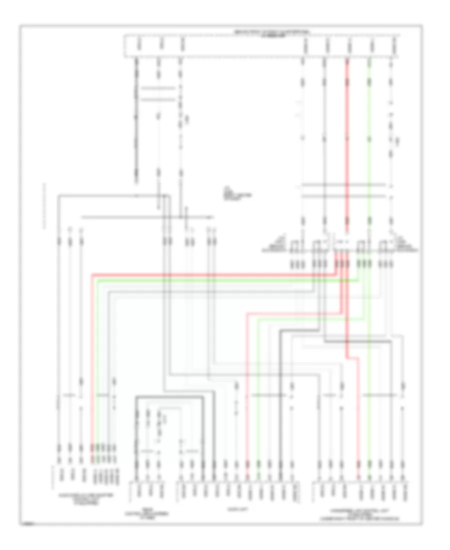
COMPUTER DATA LINES
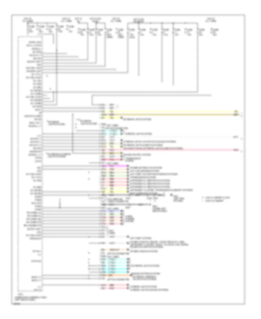
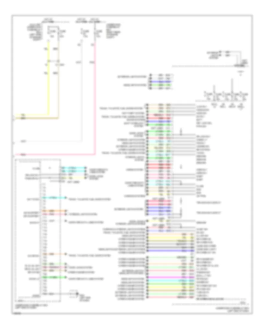
B-CAN Wiring Diagram/UART Communication Line for Honda Pilot EX-L 2014
List of elements for B-CAN Wiring Diagram/UART Communication Line for Honda Pilot EX-L 2014:
- (in steering
- 2wd w/ memory & 4wd
- 2wd w/o memory
- A19 b-can lo
- A20 b-can lo
- A21
- Audio display usb adapter control unit
- Audio unit (w/o navigation) audio navigation unit (w/ navigation)
- Automatic lighting control unit (if equipped) (left side of dash)
- B-can hi
- B-can lo
- B39 b-can lo
- B40
- C307
- C402
- C501
- C512
- C513
- C6 b-can lo
- C701
- C751
- C761
- Chk
- Climate control unit
- Column)
- Control unit
- D18
- E15
- Front passenger's power window switch
- G401 (left end of dash)
- Gauge control module
- Immobilizer
- J/c c422 (left center of dash)
- J/c c424 (right center of dash)
- Keyless
- Master switch
- Micu
- Micu service check connector
- Moonroof control unit (if equipped) (in front roof console)
- Navigation display unit
- Parking & backup sensor control unit (if equipped) (left side of dash)
- Power seat control unit (w/ memory) (under driver's seat)
- Power tailgate control unit (if equipped) (behind rear of left quarterpanel)
- Power window
- Power window master switch
- Remote starting
- S-gnd
- Seat heater control unit (w/ front seat heaters) (under driver's seat)
- System connector (option connector)
- T12
- T29
- T34
- Uart
- Under-dash fuse/relay box (left end of dash)
- W/ memory
- W/ moonroof
- W/ navigation
- W/0 navigation
- W/o memory
- W/o navigation
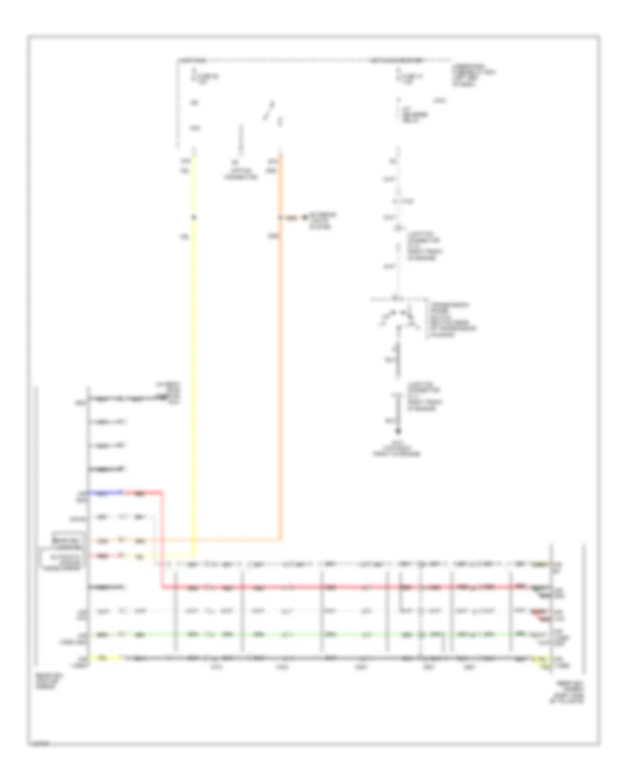
Data Link Connector Wiring Diagram for Honda Pilot EX-L 2014
List of elements for Data Link Connector Wiring Diagram for Honda Pilot EX-L 2014:
- (right rear of engine compt)
- (right side of engine compt)
- (under middle
- A11
- A16
- A17
- A18
- A20
- A22
- A32
- A48
- A49
- Audio navigation unit (w/ navigation)
- Audio unit (w/o navigation) audio navigation unit (w/ navigation)
- C201
- C203
- C303
- C307
- C402
- Control module
- Control unit (left side of engine compt)
- Data link connector (dlc) (under left center of dash)
- Diag+ b18
- Diag- b5
- Engine mount control unit (behind right kick panel)
- F-can hi
- F-can lo
- F-can-hi
- F-can-lo
- F11
- F14
- F28
- Fuse 10a
- G403 (right center of dash)
- Gauge
- Hot at all times
- Immobilizer keyless control unit (in steering column)
- J/c c421 (center of dash)
- J/c c422 (left center of dash)
- K-line
- Micu
- Navigation service check connector (behind right kick panel)
- Of dash)
- Pcm
- Red
- Remote starting system connector (option connector) (left end of dash)
- Scs
- Srs unit
- Tpms control unit (if equipped) (upper left side of dash)
- Under-dash fuse/relay box (left end of dash)
- Under-hood fuse/relay box
- Vsa modulator
- Vtm-4 control unit (4wd) (behind rear of left quarterpanel)
- Wen
- Yaw rate acceleration sensor (under middle of dash)
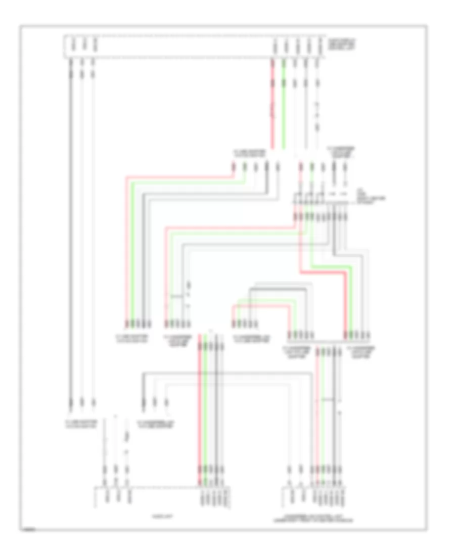
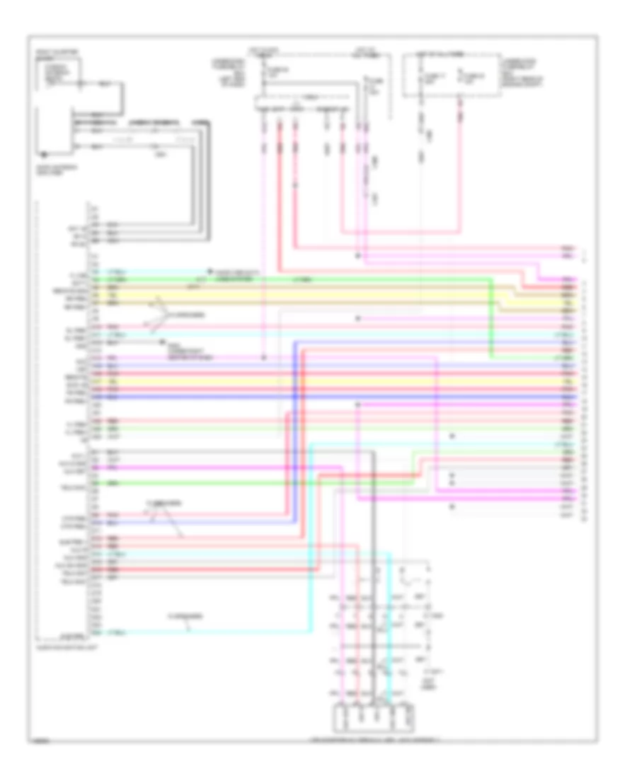
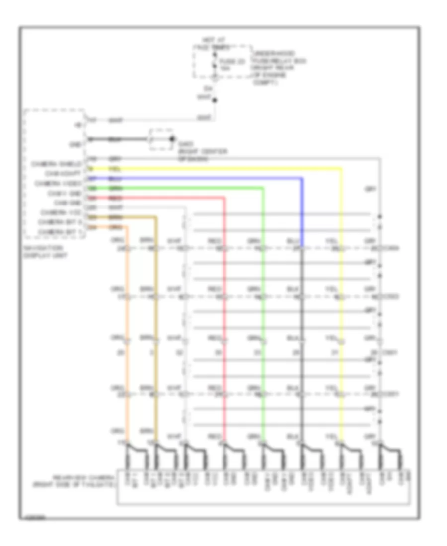
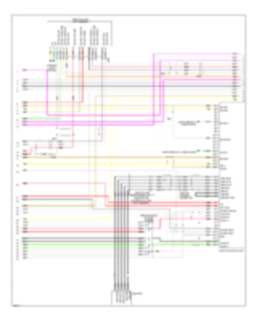
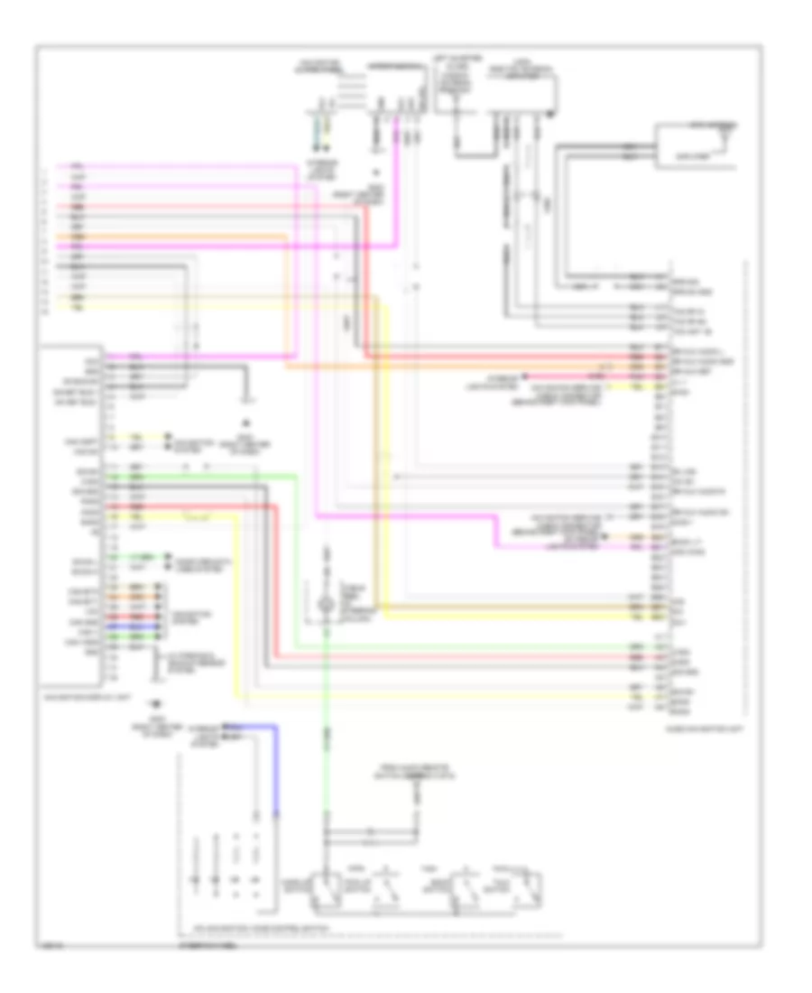
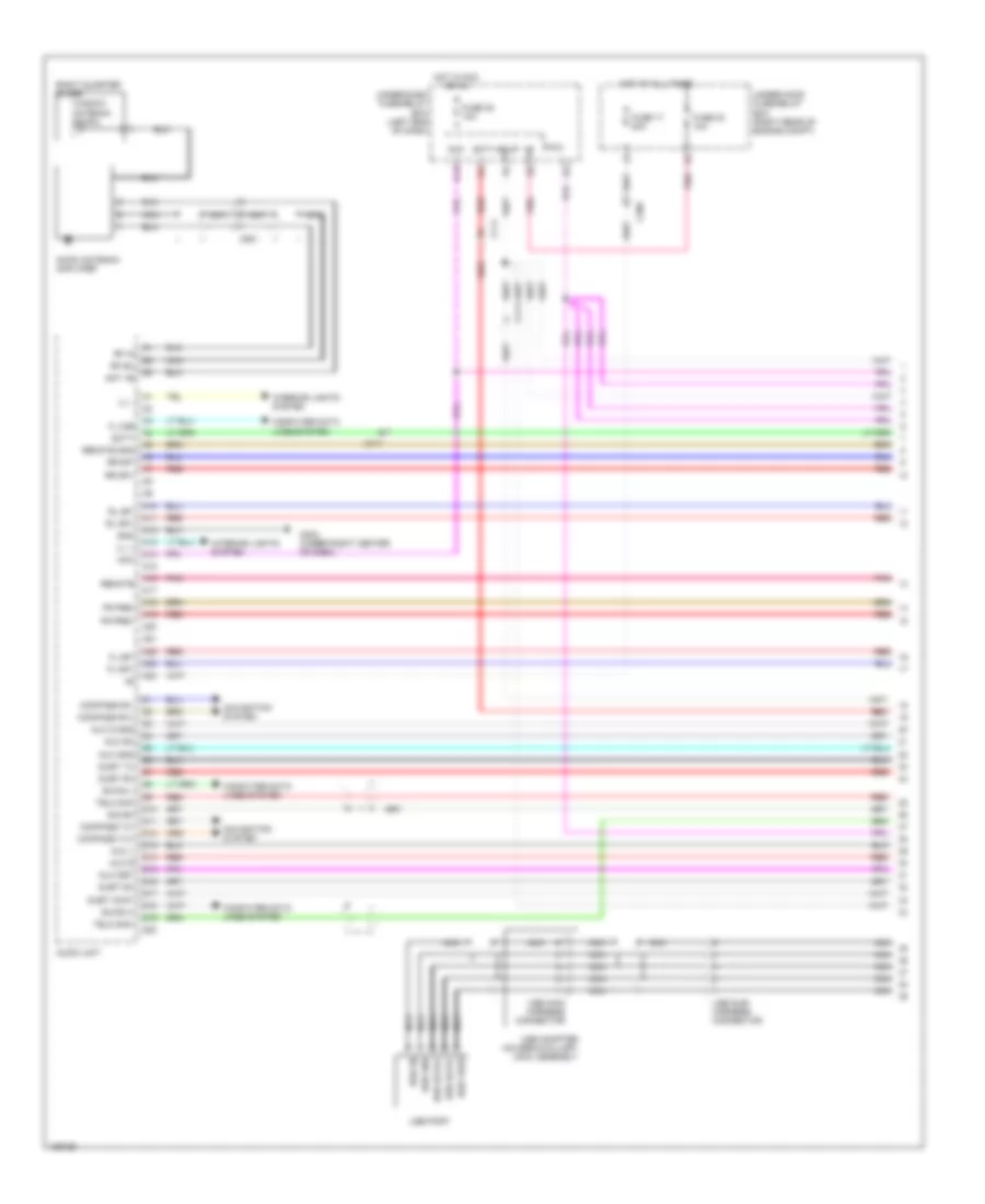
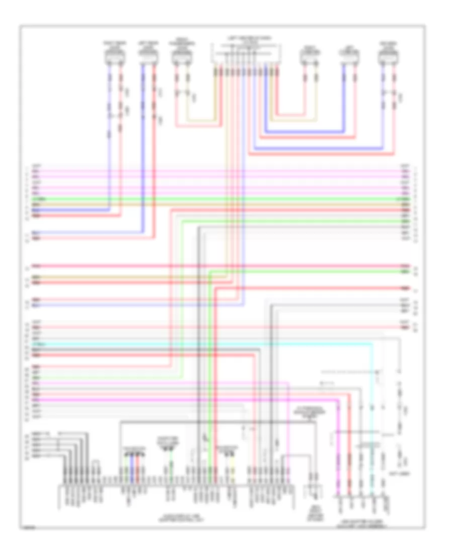
GA-NET Bus/GA-NET Audio Wiring Diagram, with Navigation for Honda Pilot EX-L 2014
List of elements for GA-NET Bus/GA-NET Audio Wiring Diagram, with Navigation for Honda Pilot EX-L 2014:
- A10
- A13
- A14
- Audio l+
- Audio l-
- Audio navigation unit
- Audio r+
- Audio r-
- Audio sh
- Bus (+)
- Bus (-)
- Bus sh
- C10
- C13
- C14
- C404
- C711
- F16
- Handsfree link control unit (if equipped) (under right front of center console)
- J/c c425 (right center of dash)
- J/c c426 (right center of dash)
- Navigation display unit
- Rear controller & screen (w/ res)
- Red
- Xm receiver (behind front of right quarterpanel)
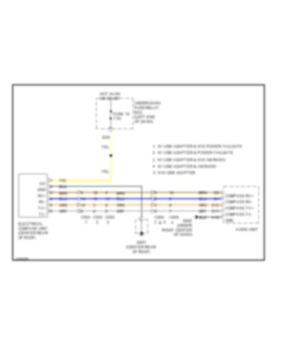
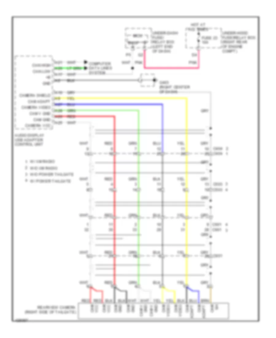
GA-NET Bus/GA-NET Audio Wiring Diagram, without Navigation with XM Radio for Honda Pilot EX-L 2014
List of elements for GA-NET Bus/GA-NET Audio Wiring Diagram, without Navigation with XM Radio for Honda Pilot EX-L 2014:
- (behind front of right quarterpanel) xm receiver
- A12
- A13
- A14
- A15
- A16
- Audio display-usb adapter control unit (if equipped)
- Audio l+
- Audio l-
- Audio r+
- Audio r-
- Audio sh
- Audio unit
- Bus (+)
- Bus (-)
- Bus sh
- C10
- C13
- C14
- C404
- C711
- F15
- Handsfree link control unit (if equipped) (under right front of center console)
- J/c c406 (behind glove box)
- J/c c407 (behind glove box)
- J/c c425 (right center of dash)
- Rear controller & screen (w/ res)
- Red
GA-NET Bus/GA-NET Audio Wiring Diagram, without Navigation without XM Radio for Honda Pilot EX-L 2014
List of elements for GA-NET Bus/GA-NET Audio Wiring Diagram, without Navigation without XM Radio for Honda Pilot EX-L 2014:
- A12
- A13
- A14
- A15
- A16
- Audio display usb adapter control unit
- Audio l+
- Audio l-
- Audio r+
- Audio r-
- Audio sh
- Audio unit
- Bus (+)
- Bus (-)
- Bus sh
- C10
- C13
- C14
- Handsfree link control unit (under right front of center console)
- J/c c426 (right center of dash)
- Red
- W/ handsfree link & usb adapter
- W/ handsfree link w/o usb adapter
- W/ usb adapter w/o navigation
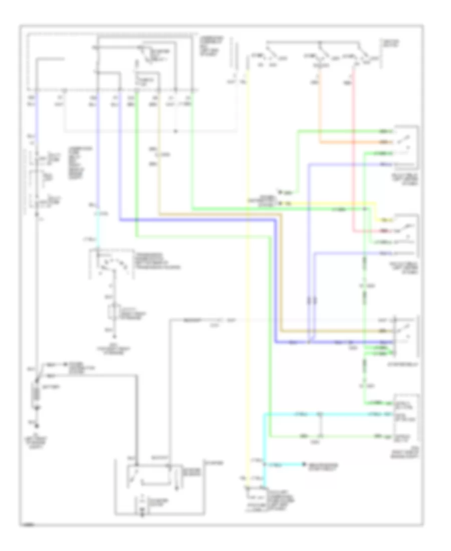
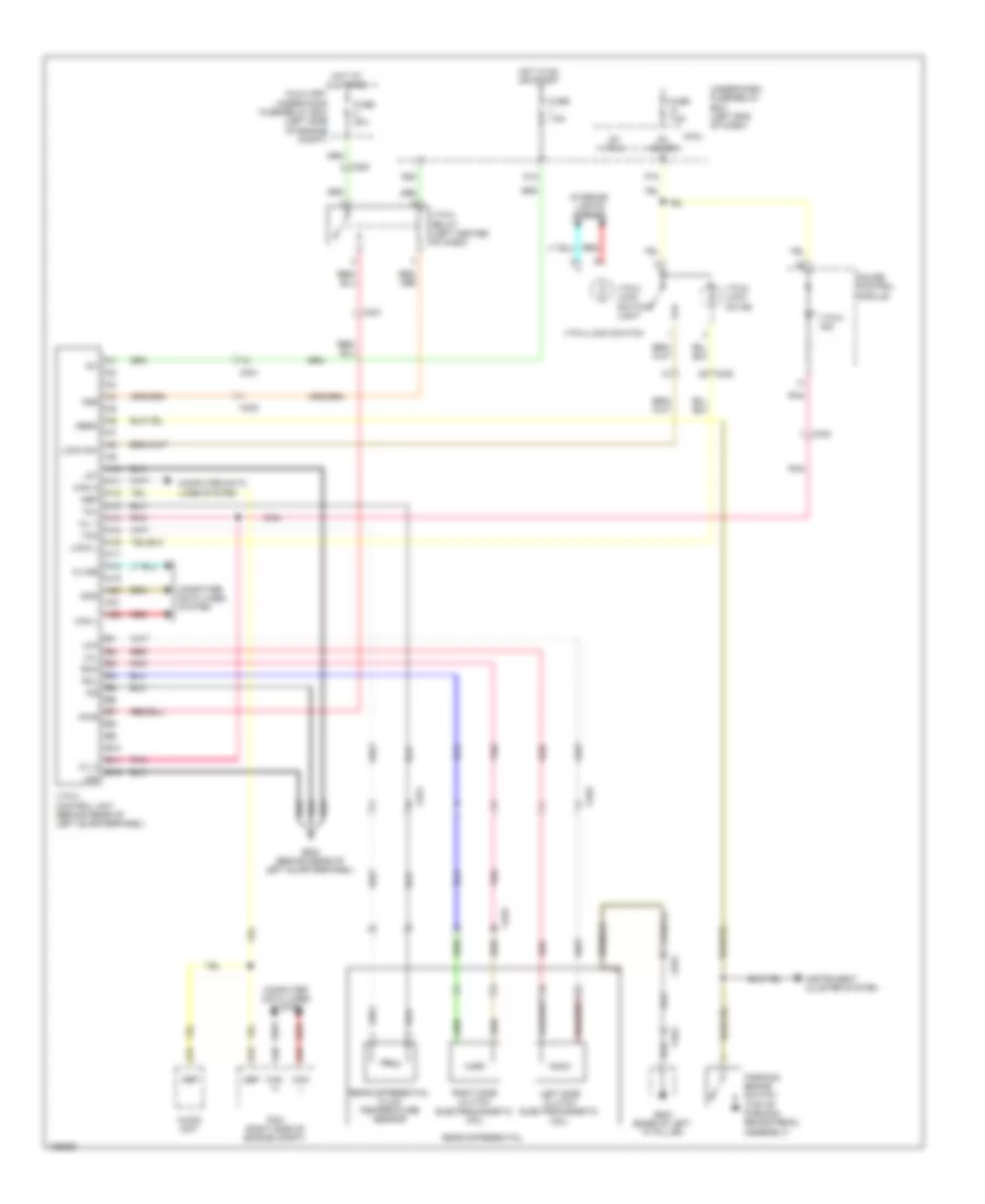
COOLING FAN
Cooling Fan Wiring Diagram for Honda Pilot EX-L 2014
List of elements for Cooling Fan Wiring Diagram for Honda Pilot EX-L 2014:
- (right front of engine) j/c c113
- (right rear of engine compt)
- A/c condenser fan diode
- A/c condenser fan motor (behind right side of radiator)
- A/c condenser fan relay
- A/c pressure
- A/c pressure sens
- A19
- A21
- A23
- A37
- A40
- A48
- A49
- Air conditioning system
- B-can hi
- B-can lo
- C16
- C301
- C303
- C32
- Canh
- Canl
- Climate control unit
- Common potential
- Computer data lines system
- Ect sensor 1 (left rear of engine)
- Ect sensor 2 (lower left rear of radiator)
- Engine controls system
- F11
- F12
- F14
- F16
- Fan control relay
- Front blower motor relay (behind right kick panel)
- Fuse 10a
- Fuse 15 7.5a
- Fuse 15a
- Fuse 30a
- G101 (top right front of engine)
- G12
- G201 (under right front of engine compt)
- G202 (right side of engine compt)
- Gnd
- Hot at all times
- Hot in on
- J/c c114 (right front of engine)
- Of dash)
- Pcm (right side of engine compt)
- Pgm-fi sub-relay
- Pnk
- Radiator fan diode
- Radiator fan motor (behind left side of radiator)
- Radiator fan relay
- Red
- Rly ctrl (fanh)
- Rly ctrl (fanl)
- Rly ctrl (sub rly)
- Sens common gnd
- Sens gnd (sg2)
- Sens gnd (sg7)
- Sens in (ect1)
- Sens in (ect2)
- Sensor
- Under-dash fuse/relay box (left end
- Under-hood fuse/relay box (right rear of engine compt)
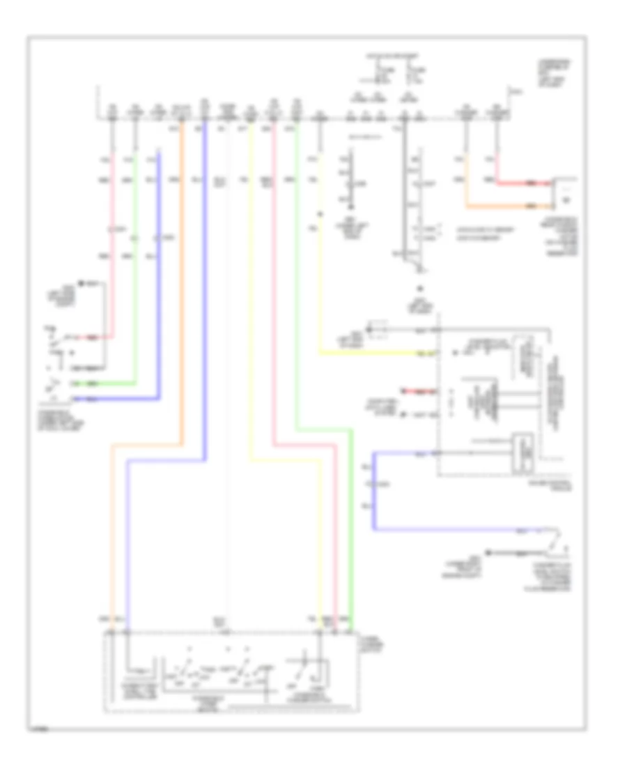
CRUISE CONTROL
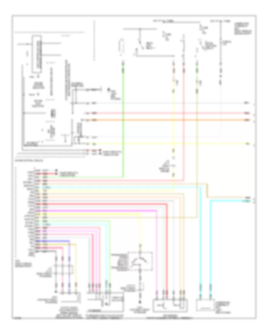
Cruise Control Wiring Diagram (1 of 2) for Honda Pilot EX-L 2014
List of elements for Cruise Control Wiring Diagram (1 of 2) for Honda Pilot EX-L 2014:
- A18
- A19
- A24
- A25
- A26
- A27
- A29
- A48
- A49
- App sensor (top of accelerator pedal assembly)
- Apsa
- Apsb
- Area network controller 5v stabilizer circuit/controller
- Atpfwd
- B17
- B18
- B26
- B33
- B34
- B36
- B38
- Bksw
- Bkswnc
- C102
- C18
- Canh
- Canl
- Circuit dimming
- Circuit stabilizer 10v
- Computer data lines system
- Cruise control indicator
- Cruise main indicator
- Etcs control relay
- Etcsm+
- Etcsm-
- Etcsrly
- F25
- F30
- Fuse 15a
- Fuse 23 10a
- G101 (top right front of engine)
- G401 (left end of dash)
- Gauge control module
- Gauges & indicators
- Gnd (pg2)
- Hot at all times
- Ig1etcs
- Igp
- Indicator drive circuit
- Indicators gauges &
- J/c c111 (right front of engine)
- J/c c113 (right front of engine)
- Mrly
- Network transceiver fast controller area
- Output shaft (counter shaft) speed sensor (bottom left side of transmission housing)
- Pcm (right side of engine compt)
- Pgm-fi main relay 1
- Pnk
- Red
- Sg1
- Sg3
- Sg4
- Sg5
- Tan
- Throttle actuator
- Tp sensor
- Tp sensor/throttle actuator (on throttle body assembly)
- Tpsa
- Tpsb
- Transmission range switch (bottom rear of transmission housing)
- Under-dash fuse/relay box (left end of dash)
- Under-hood fuse/relay box (right rear of engine compt)
- Vcc1
- Vcc3
- Vcc4
- Vcc5
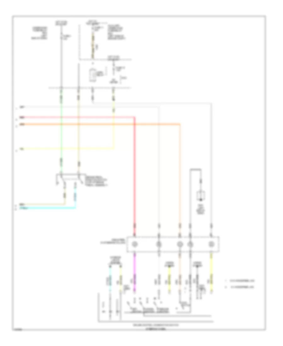
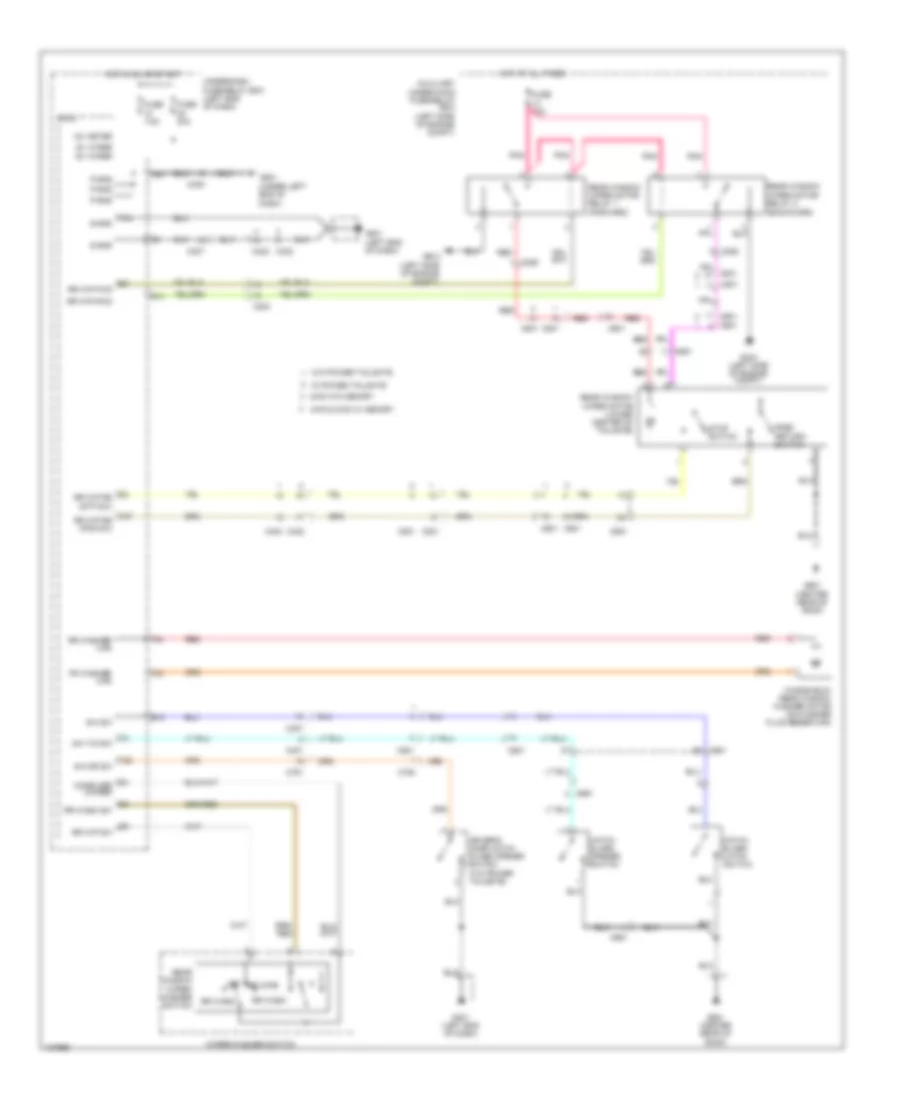
Cruise Control Wiring Diagram (2 of 2) for Honda Pilot EX-L 2014
List of elements for Cruise Control Wiring Diagram (2 of 2) for Honda Pilot EX-L 2014:
- (not used)
- (or red)
- Auxiliary under-hood fuse/relay box (left side of engine compt)
- Brake pedal position switch (top of brake pedal assembly)
- C10
- C11
- C12
- C201
- Cable reel (in steering column)
- Cancel switch
- Cruise control combination switch
- Fuse 10 7.5a
- Fuse 11 20a
- Fuse 3 10a
- G16
- G401 (left end of dash)
- Horn relay
- Horns system
- Hot at all times
- Hot in on or start
- Ig1 meter
- Interior lights system
- Main switch
- Micu
- Red
- Resume switch
- Set switch
- Steering wheel
- Under-dash fuse/relay box (left end of dash)
- W/ handsfree link
- W/o handsfree link
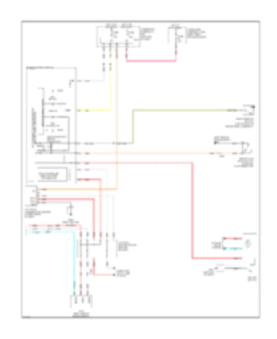
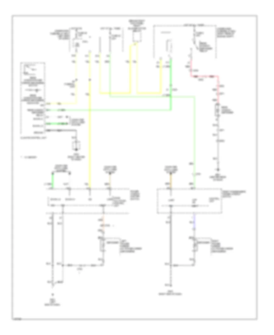
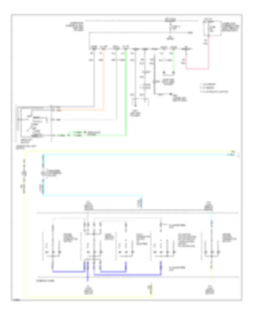
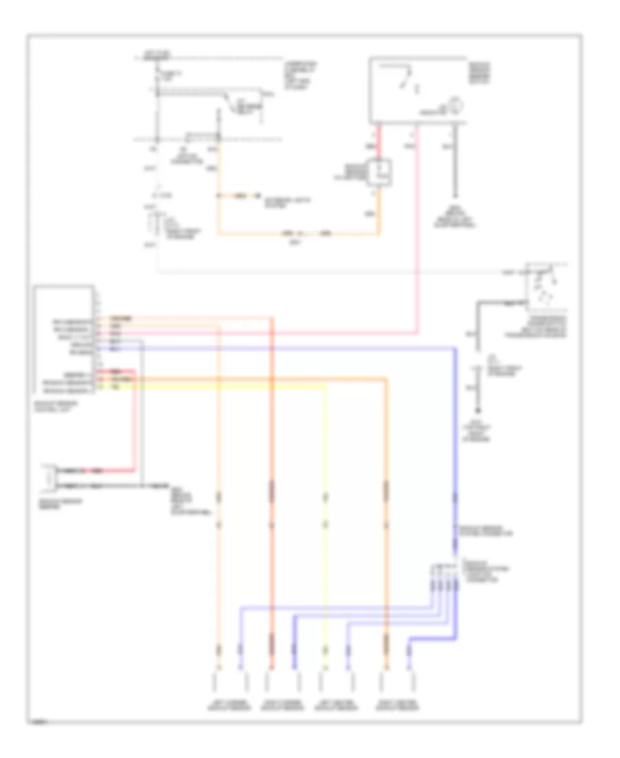
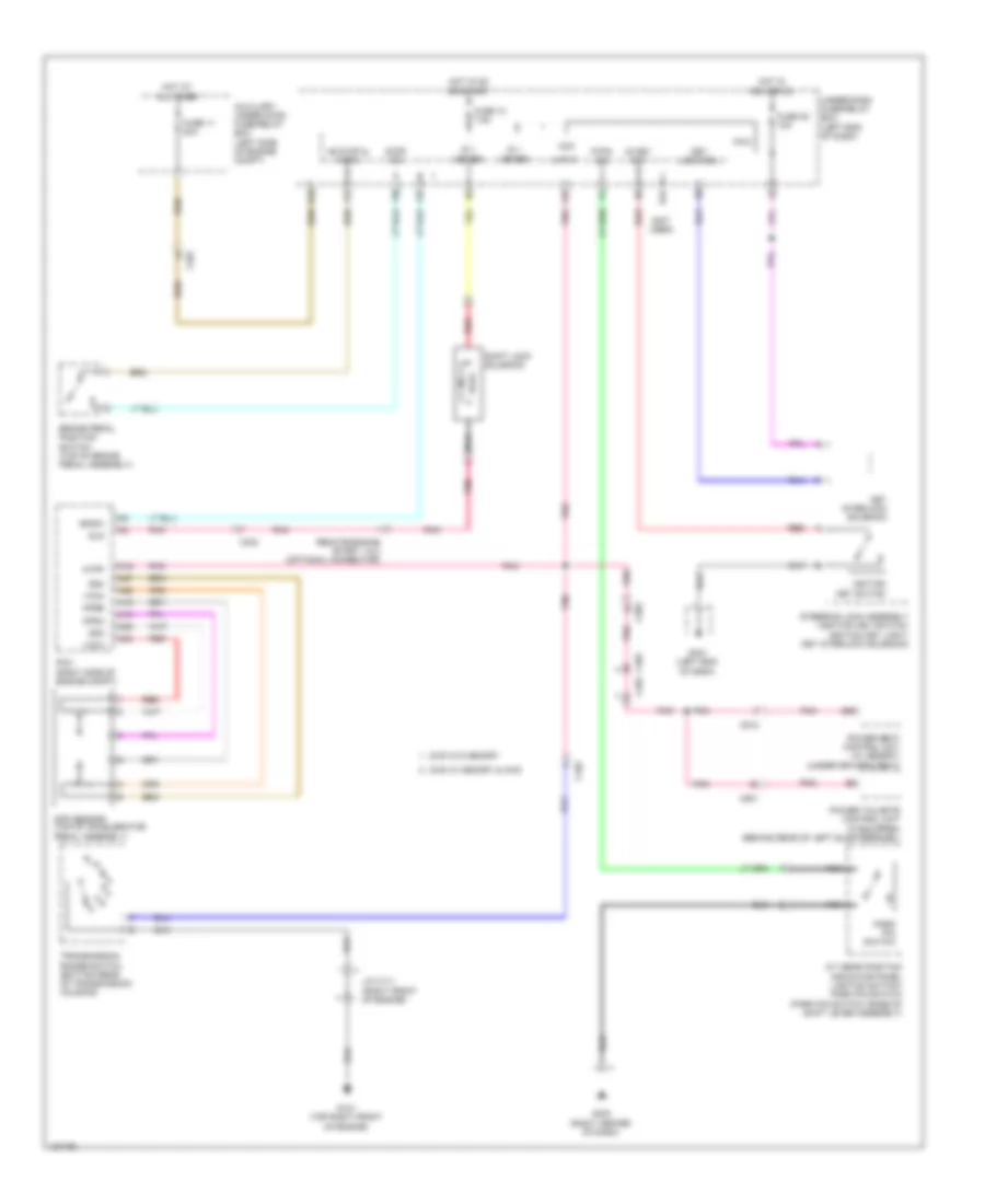
DEFOGGERS
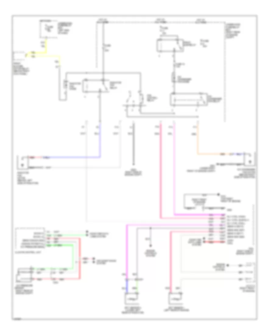
Defoggers Wiring Diagram for Honda Pilot EX-L 2014
List of elements for Defoggers Wiring Diagram for Honda Pilot EX-L 2014:
- (behind right kick panel) front blower motor relay
- A18
- A19
- A36
- B-can hi
- B-can lo
- B11
- C303
- C308
- C502
- C602
- C671
- C753
- C761
- Climate control unit
- Computer data lines system
- Control unit
- Defogger
- Door multiplex control unit
- F17
- Front passenger's power window switch
- Fuse 30 20a
- Fuse 36 10a
- Fuse 8 30a
- G12
- G401 (left end of dash)
- G403 (right center of dash)
- G404 (right end of dash)
- G601 (center rear of roof)
- Ground
- Heat
- Hot at all times
- Hot in on
- Ig2
- Ig2 hac
- Left power mirror (w/ power mirror defoggers)
- Micu
- N11
- Power window master switch
- Q16
- Rear window defogger
- Rear window defogger relay
- Rear window/power mirror defoggers indicator
- Rear window/power mirror defoggers switch
- Red
- Right power mirror (w/ power mirror defoggers)
- S4 (thermal cap)
- Uart
- Under-dash fuse/relay box (left end of dash)
- Under-hood fuse/relay box (right rear of engine compt)
- Vmp as
- W/ memory
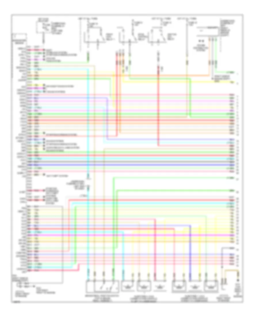
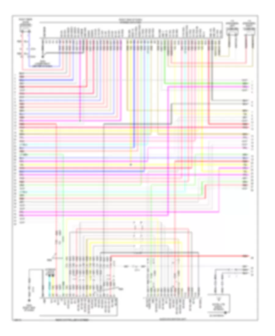
ENGINE PERFORMANCE
3.5L
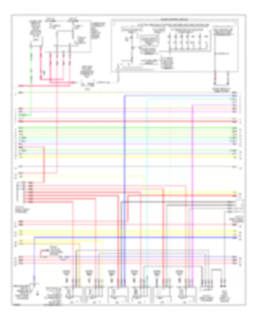
3.5L, Engine Performance Wiring Diagram (1 of 6) for Honda Pilot EX-L 2014
List of elements for 3.5L, Engine Performance Wiring Diagram (1 of 6) for Honda Pilot EX-L 2014:
- (right side of engine compt) g202
- A10
- A11
- A12
- A13
- A14
- A15
- A16
- A17
- A18
- A19
- A20
- A21
- A22
- A23
- A24
- A25
- A26
- A27
- A28
- A29
- A30
- A31
- A32
- A33
- A34
- A35
- A36
- A37
- A38
- A39
- A40
- A41
- A42
- A43
- A44
- A45
- A46
- A47
- A48
- A49
- Acc
- Air conditioning system
- Anti-theft system
- Apsa
- Apsb
- Atpp
- B10
- B11
- B12
- B13
- B14
- B15
- B16
- B17
- B18
- B19
- B20
- B21
- Barometer sensor
- Bksw
- Bkswnc
- Brake pedal position switch (top of brake pedal assembly)
- C102
- Canh
- Canl
- Ckpout
- Cmpout
- Computer data lines system
- Cooling fans system
- Cssama
- Cssamc
- D3sw
- Ect2
- Eld
- Eld unit
- Etcs control relay
- Etcsrly
- F17
- F25
- F30
- Fanh
- Fanl
- Ftp
- Fuse 16 7.5a
- Fuse 18 15a
- Fuse 19 15a
- Fuse 21 15a
- Fuse 7.5a
- G101 (top right front of engine)
- Hot at all times
- Hot in on or start
- Ignition coil relay
- Igp
- Igpls5
- Igpls6
- Imofpr
- Imtm
- Inj1
- Inj2
- Inj3
- Inj4
- Inj5
- Inj6
- Injectors 1, 2 & 3 (under intake manifold, in right cylinder bank)
- Injectors 4, 5 & 6 (under intake manifold, in left cylinder bank)
- J/c c112 (right front of engine)
- J/c c113 (right front of engine)
- Lg3
- Lsb
- Lsc
- Mrly
- Nca
- Nep
- Pcm (right side of engine compt)
- Pg2
- Pgm-fi main relay 1
- Pnk
- Power distribution system
- Pspsw
- Red
- S net
- Scs
- Sg3
- Sg4
- Sg7
- Shift interlock system starting/charging system
- Sho2sb2
- Sls
- Sound systems
- Starting/ charging & anti-theft systems
- Starting/charging system
- Strld
- Strly
- Sts
- Subrly
- Tan
- Tpsa
- Under-dash fuse/relay box (left end of dash)
- Under-hood fuse/relay box (right rear of engine compt)
- Vbsol1
- Vbsol2
- Vbum
- Vcc3
- Vcc4
- Vcc5
- Vcc7
- Vcentb2
- Vcmswc
- Vg+
- Vg-
- Vsb1
- Vsb2
- Vssout
- Vsv
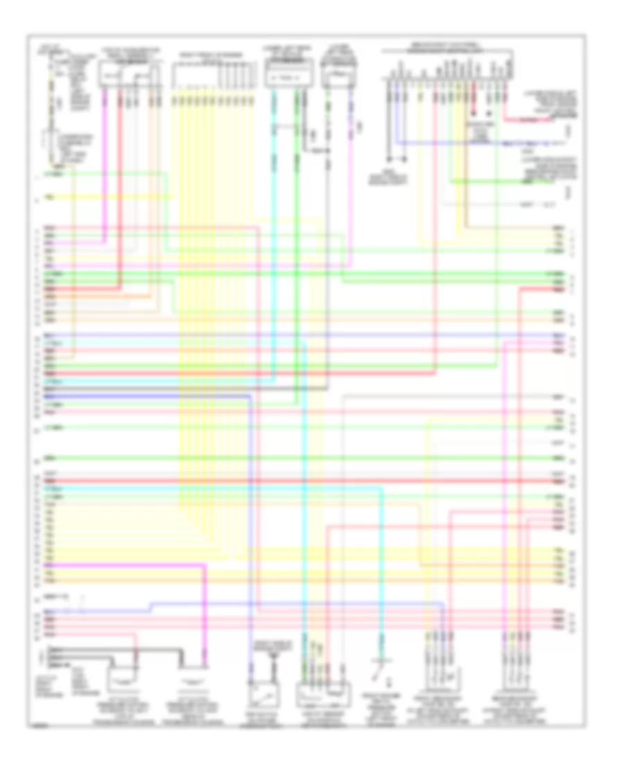
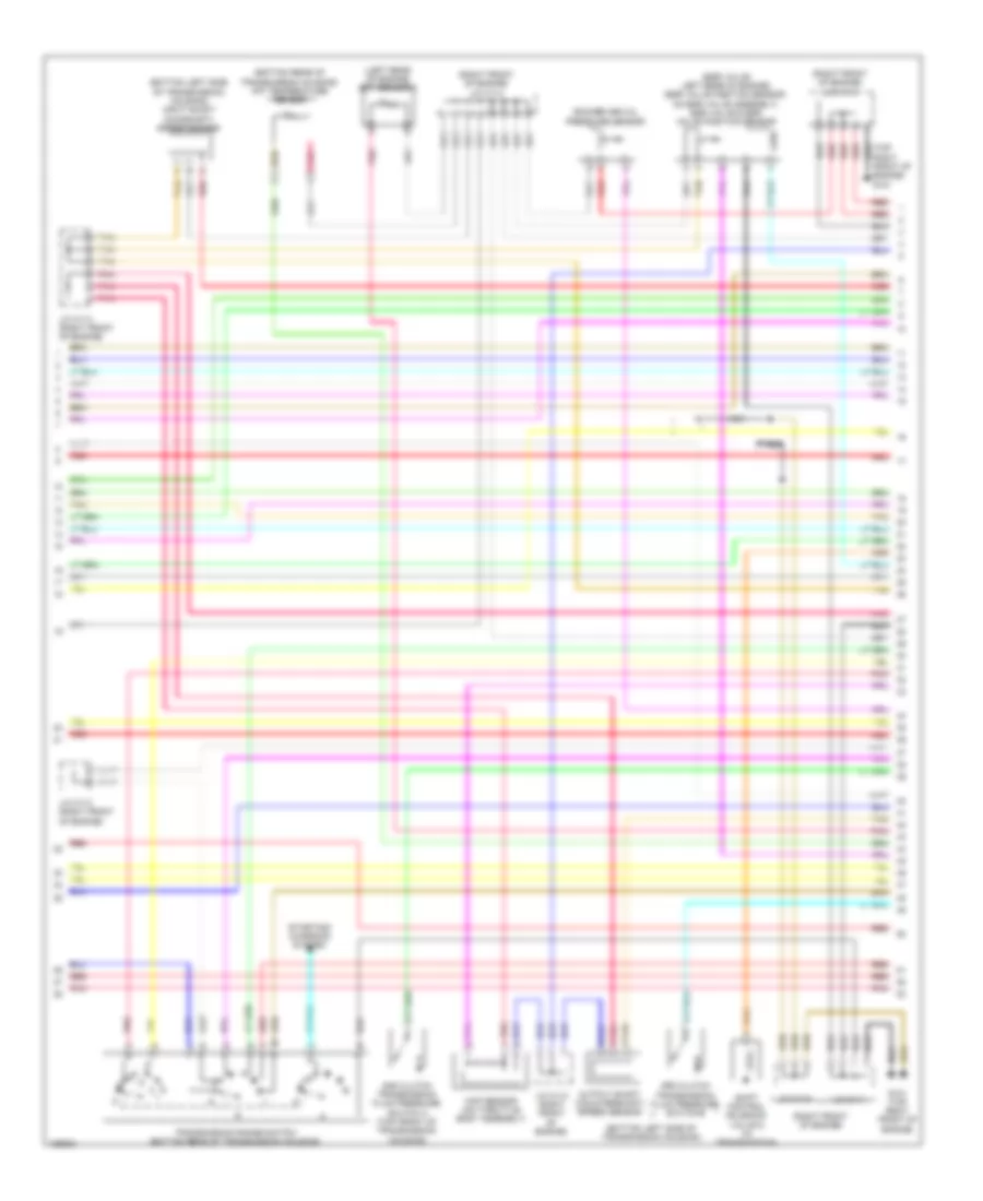
3.5L, Engine Performance Wiring Diagram (2 of 6) for Honda Pilot EX-L 2014
List of elements for 3.5L, Engine Performance Wiring Diagram (2 of 6) for Honda Pilot EX-L 2014:
- (behind right kick panel) engine mount control unit
- (lower left rear of radiator) ect sensor 2
- (lower middle left side of engine) front engine mount control actuator
- (lower middle right side of engine) rear engine mount control actuator
- (right front of engine) j/c c111
- (right side of engine compt) g202
- (top of accelerator pedal assembly) app sensor
- (under left rear of vehicle) ftp sensor
- A/t clutch pressure control solenoid valve b (rear of transmission housing)
- A/t clutch pressure control solenoid valve c (top of transmission housing)
- Auxiliary under- hood fuse/ relay box (left side of engine compt)
- C102
- C201
- C301
- C302
- C306
- Can h
- Can l
- Ckp
- Cmp
- Computer data lines system
- F31
- Front rocker arm oil pressure switch (left front of engine)
- Front secondary ho2s (b2, s2) (in left bank exhaust, downstream of catalytic converter)
- Fuse 20a
- G101 (top right front of engine)
- G16
- G202 (right side of engine compt)
- Hot at all times
- Iat
- Ig1
- Igsol
- J/c c113 (right front of engine)
- Maf
- Maf/iat sensor (on manifold air intake duct)
- Nca
- Pnk
- Psp switch (on power steering pump)
- Rear secondary ho2s (b1, s2) (in right bank exhaust, downstream of catalytic converter)
- Red
- Solfm
- Solfp
- Solrly
- Solrm
- Solrp
- Tan
- Under-dash fuse/relay box (left end of dash)
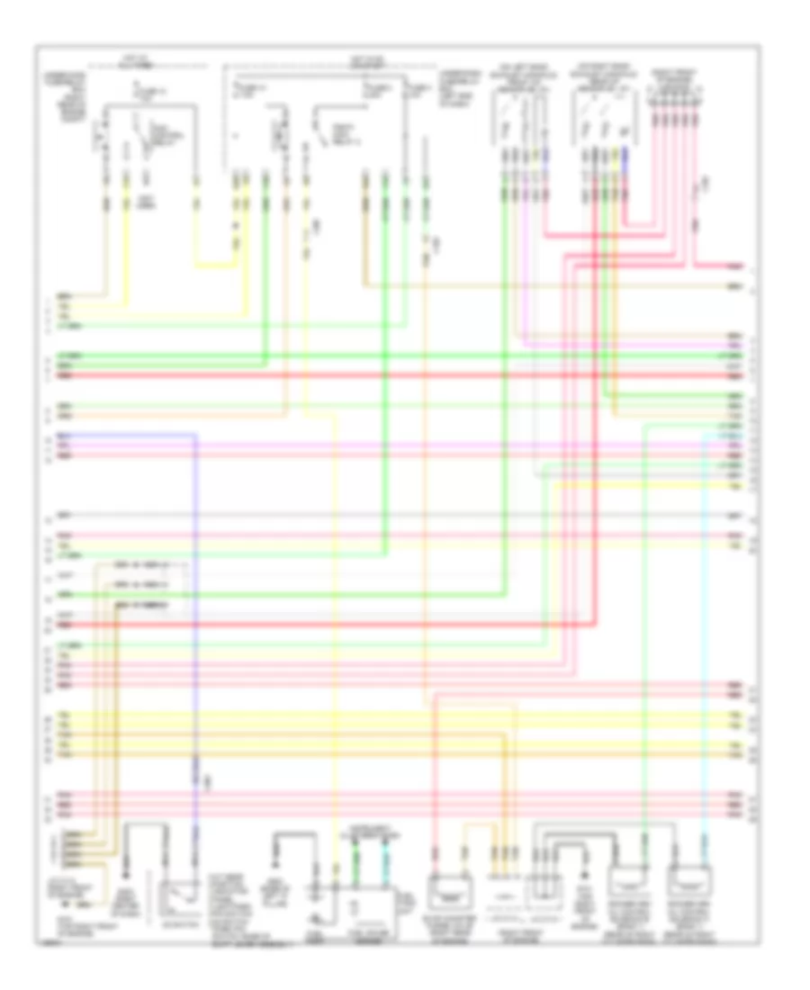
3.5L, Engine Performance Wiring Diagram (3 of 6) for Honda Pilot EX-L 2014
List of elements for 3.5L, Engine Performance Wiring Diagram (3 of 6) for Honda Pilot EX-L 2014:
- (not used)
- (on left bank exhaust manifold) front a/f sensor (b2, s1)
- (on right bank exhaust manifold) rear a/f sensor (b1, s1)
- (right front of engine)
- (right front of engine) j/c c112
- A/t gear position indicator panel light/park pin switch/ d3 switch (park pin switch: base of shift lever assembly)
- Acm control relay
- C102
- C303
- C307
- D3 switch
- E27
- E28
- Evap canister purge valve (right rear of engine)
- F10
- F15
- F24
- Fuel gauge sender
- Fuel pump
- Fuel tank unit
- Fuse 10 7.5a
- Fuse 12 10a
- Fuse 2 20a
- Fuse 3 10a
- G101 (top right front of engine)
- G403 (right center of dash)
- G503 (base of left "c" pillar)
- Hot at all times
- Hot in on or start
- Instrument cluster system
- J/c c112 (right front of engine)
- J/c c113
- J/c c114
- Nca
- Pgm-fi main relay 2
- Pnk
- Red
- Rocker arm oil control solenoid a (bank 1) (rear of right cylinder bank)
- Rocker arm oil control solenoid b (bank 1) (rear of right cylinder bank)
- Tan
- Under-dash fuse/relay box (left end of dash)
- Under-hood fuse/relay box (right rear of engine compt)
3.5L, Engine Performance Wiring Diagram (4 of 6) for Honda Pilot EX-L 2014
List of elements for 3.5L, Engine Performance Wiring Diagram (4 of 6) for Honda Pilot EX-L 2014:
- (left end of dash)
- (under left rear of vehicle) evap canister vent shut valve
- 10v stabilizer circuit
- 5v stabilizer circuit/controller area network controller
- A/t gear position indicator dimming circuit
- A/t gear position indicator drive circuit
- Back up
- C102
- C306
- Compulsory turning off circuit
- Compulsory turning on circuit
- Computer data lines system
- F16
- F18
- Fail-safe circuit
- Fast controller area network transceiver
- Fuse 11 15a
- Fuse 23 10a
- G101 (top right front of engine)
- Gauge control module
- Hot at all times
- Icm
- Ignition coils 1, 2, 3, 4, 5 & 6 (1, 2 & 3: top of right cylinder bank) (4, 5 & 6: top of left cylinder bank)
- Indicator drive circuit
- J/c c111 (right front of engine)
- J/c c112 (right front of engine)
- J/c c113 (right front of engine)
- Micu
- Mil ind
- Pgm fi sub relay
- Pnk
- Rear rocker arm oil pressure switch (right rear of engine)
- Red
- Spark plug
- Tan
- Trunk, tailgate, fuel doors system
- Under-dash fuse/relay box
- Under-hood fuse/relay box (right rear of engine compt)
3.5L, Engine Performance Wiring Diagram (5 of 6) for Honda Pilot EX-L 2014
List of elements for 3.5L, Engine Performance Wiring Diagram (5 of 6) for Honda Pilot EX-L 2014:
- (bottom left side of transmission housing)
- (bottom left side of transmission housing) input shaft (mainshaft) speed sensor
- (bottom rear of transmission housing) atf temperature sensor
- (egr valve: left rear of engine) (egr valve position sensor: on egr valve assembly) egr valve & egr valve position sensor
- (left rear of engine) ect sensor 1
- (right front of engine)
- (right front of engine) j/c c113
- (right front of engine) j/c c114
- 2nd clutch transmission fluid pressure switch a (top front of transmission housing)
- 3rd clutch transmission fluid pressure switch b
- G101 (top right front of engine)
- J/c c111
- J/c c112
- J/c c113 (right front of engine)
- Map sensor (on throttle body assembly)
- Nca
- Output shaft (countershaft) speed sensor
- Pnk
- Red
- Rocker arm oil pressure sensor
- Shift control solenoid valve d (in transmission)
- Starting/ charging system
- Tan
- Transmission range switch (bottom rear of transmission housing)
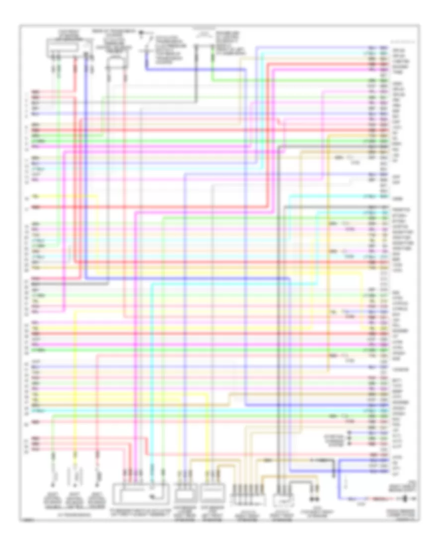
3.5L, Engine Performance Wiring Diagram (6 of 6) for Honda Pilot EX-L 2014
List of elements for 3.5L, Engine Performance Wiring Diagram (6 of 6) for Honda Pilot EX-L 2014:
- (in transmission)
- (rear of transmission housing) a/t clutch pressure control solenoid valve a
- (top front of engine) imt actuator
- 4th clutch transmission fluid pressure switch c (top rear of transmission housing)
- Afshtcb1
- Afshtcb2
- Altc
- Altf
- Altl
- Atp1
- Atp2
- Atpd
- Atpfwd
- Atpn
- Atpr
- Atprvs
- B22
- B23
- B24
- B25
- B26
- B27
- B28
- B29
- B30
- B31
- B32
- B33
- B34
- B35
- B36
- B37
- B38
- B39
- B40
- B41
- B42
- B43
- B44
- B45
- B46
- B47
- B48
- B49
- C10
- C102
- C11
- C12
- C13
- C14
- C15
- C151
- C152
- C16
- C17
- C18
- C19
- C20
- C21
- C22
- C23
- C24
- C25
- C26
- C27
- C28
- C29
- C30
- C31
- C32
- C33
- C34
- C35
- C36
- C37
- C38
- C39
- C40
- C41
- C42
- C43
- C44
- C45
- C46
- C47
- C48
- C49
- Ckp
- Ckp sensor (lower right rear of engine)
- Cmp
- Cmp sensor (top left front of engine)
- Cssa
- Cssb
- Cssc
- Ect1
- Egr
- Egrp
- Etcsm+
- Etcsm-
- G101 (top right front of engine)
- Iat
- Ig1
- Ig1etcs
- Igpls1
- Igpls2
- Igpls3
- Igpls4
- Imt+
- Imt-
- Ipb1
- Ipb2
- J/c c111 (right front of engine)
- J/c c112 (right front of engine)
- Knock sensor (under intake manifold)
- Lg1
- Lg2
- Lsa
- Map
- Nca
- Op2sw
- Op3sw
- Op4sw
- Pcm (right side of engine compt)
- Pcs
- Pg1
- Pgmetcs
- Pnk
- Poil
- Red
- Rocker arm oil control solenoid a (bank 2) (front of left cylinder bank)
- Sg1
- Sg2
- Sg5
- Sha
- Shb
- Shc
- Shd
- Shift control solenoid valve a
- Shift control solenoid valve b
- Shift control solenoid valve c
- Sho2sb1
- So2sgb1
- So2sgb2
- So2shtcb1
- So2shtcb2
- Starting/ charging system
- Tan
- Tatf
- Tp sensor/throttle actuator (on throttle body assembly)
- Tpsb
- Vcc1
- Vcc2
- Vcc6
- Vcentb2
- Vcmswb
EXTERIOR LIGHTS
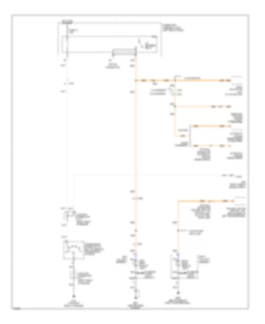
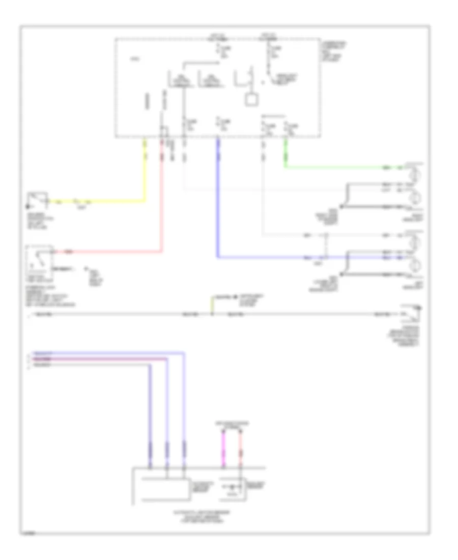
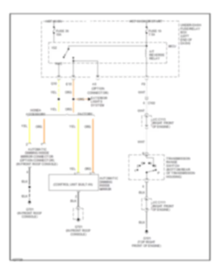
Backup Lamps Wiring Diagram for Honda Pilot EX-L 2014
List of elements for Backup Lamps Wiring Diagram for Honda Pilot EX-L 2014:
- (option
- A/t reverse relay
- Atpr
- Audio navigation unit (w/ navigation)
- Automatic dimming inside mirror
- Automatic dimming inside mirror (if equipped)
- B20
- C102
- C25
- C303
- C306
- C501
- C701
- Connector)
- E15
- Exterior lamps circuit
- Factory
- Fuse 10 7.5a
- G101 (top right front of engine)
- G505 (behind rear of right quarterpanel)
- G601 (center rear of roof)
- Honda accessory
- Hot in on or start
- Junction connector c111 (right front of engine)
- Junction connector c113 (right front of engine)
- Left rear backup light
- Left taillight assembly
- Micu
- Optional connector (automatic dimming inside mirror)
- Optional connector trailer lighting control unit (w/o factory installed)
- Pcm (right side of engine compt)
- Rearview monitor mirror (if equipped)
- Right rear backup light
- Right taillight assembly
- Trailer lighting control unit (behind rear of left quarterpanel)
- Transmission range switch (bottom rear of transmission housing)
- Under-dash fuse/relay box (left end of dash)
- W/ moonroof
- W/ navigation
- W/o factory installed
- W/o moonroof
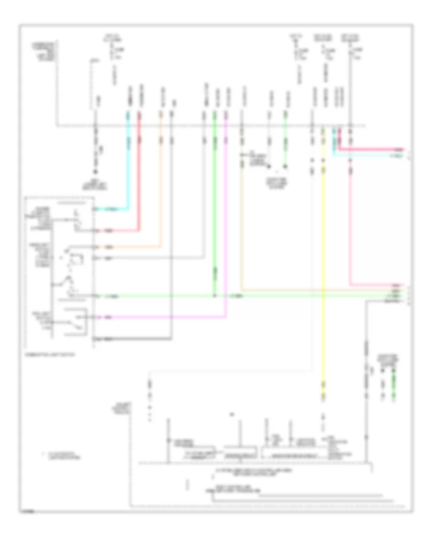
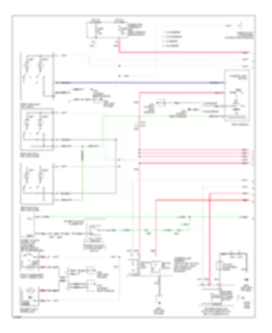
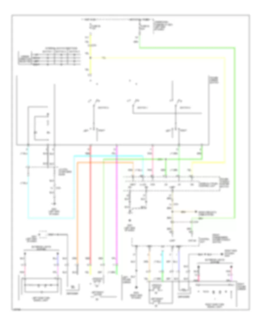
Exterior Lamps Wiring Diagram, with Factory-Installed Trailer Lighting Connector (1 of 4) for Honda Pilot EX-L 2014
List of elements for Exterior Lamps Wiring Diagram, with Factory-Installed Trailer Lighting Connector (1 of 4) for Honda Pilot EX-L 2014:
- (not used)
- +b stop & horn
- 0) off 1) park 2) auto 3) head
- 2wd w/ memory & 4wd
- 2wd w/o memory
- B-can
- Backup
- Brake pedal position switch (top of brake pedal assembly)
- C201
- C205
- C306
- C307
- C308
- C401
- C402
- Combi gnd
- Combination light switch
- Computer data lines
- Day lt
- E19
- E40
- F20
- F31
- Fuse 10a
- Fuse 15a
- Fuse 7.5a
- G16
- G201 (under right front of engine compt)
- G301 (under left front of engine compt)
- G401 (left end of dash)
- G501 (under left side of dash)
- H/l off sw
- H/l on sw
- Haz sw
- Headlight switch
- Hot at all times
- Hot in on
- Ig2
- Left front side marker light
- Left front turn signal/ parking light
- Micu
- P-gnd
- Pnk
- Q11
- Right front side marker light
- Right front turn signal/ parking light
- S-gnd
- S11
- S13
- S18
- S19
- Small lt sw
- System
- T12
- T29
- T34
- Taillight relay
- Turn l sw
- Turn r sw
- Turn signal switch
- Turn signal/ hazard flasher circuit
- Under-dash fuse/relay box (left end of dash)
- Under-hood fuse/relay box (right rear of engine compt)
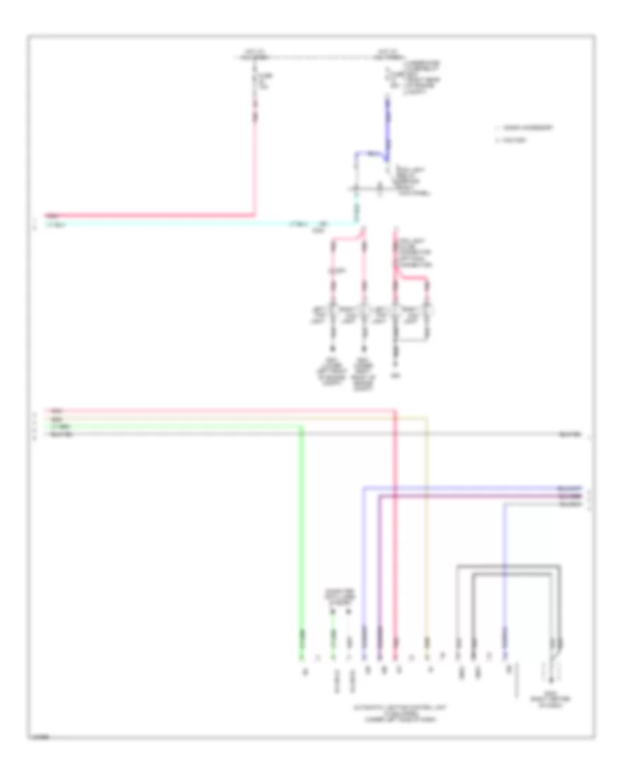
Exterior Lamps Wiring Diagram, with Factory-Installed Trailer Lighting Connector (2 of 4) for Honda Pilot EX-L 2014
List of elements for Exterior Lamps Wiring Diagram, with Factory-Installed Trailer Lighting Connector (2 of 4) for Honda Pilot EX-L 2014:
- Backup lamps circuit
- C306
- C307
- C501
- C601
- C602
- C651
- C661
- C751
- C753
- C761
- E34
- F30
- G401 (left end of dash)
- G404 (right end of dash)
- G505 (behind rear of right quarterpanel)
- G601 (center rear of roof)
- Hazard warning switch
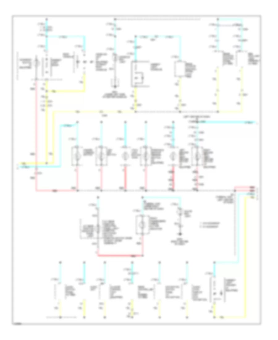
- High mount brake light
- Interior lights system
- Left license plate light
- Left power mirror (w/ side turn signals)
- Left rear brake light/ taillight
- Left rear side marker light
- Left rear turn signal light/ taillight
- Left side turn signal light
- Left taillight assembly
- Pnk
- Red
- Right license plate light
- Right power mirror (w/ side turn signals)
- Right rear brake light/ taillight
- Right rear side marker light
- Right rear turn signal light/ taillight
- Right side turn signal light
- Right taillight assembly
- Under-dash fuse/relay box (left side of dash)
- W/ memory
- W/ power tailgate
- W/o memory
- W/o power tailgate
Exterior Lamps Wiring Diagram, with Factory-Installed Trailer Lighting Connector (3 of 4) for Honda Pilot EX-L 2014
List of elements for Exterior Lamps Wiring Diagram, with Factory-Installed Trailer Lighting Connector (3 of 4) for Honda Pilot EX-L 2014:
- (not used)
- 20a
- 7.5a
- Brake
- Brake lts
- C401
- C402
- C561
- C562
- Elec brake
- Fuse 1
- Fuse 10a
- Fuse 2
- Fuse 3
- Fuse 4
- G401 (left end of dash)
- G503 (base of left "c" pillar)
- G504 (behind rear of left quarterpanel)
- Gnd
- Hot in on
- Ig2 hac
- Micu
- Pnk
- Q16
- Rear fuse/relay box (left side of cargo area)
- Red
- S4 (thermal cap)
- Trailer electric brake unit (if equipped) (left kick panel)
- Trailer electric brake unit connector
- Trailer ig2 relay
- Trailer lighting connector (under left side of rear bumper)
- Trailer taillight relay
- Under-dash fuse/relay box (under left side of dash)
Exterior Lamps Wiring Diagram, with Factory-Installed Trailer Lighting Connector (4 of 4) for Honda Pilot EX-L 2014
List of elements for Exterior Lamps Wiring Diagram, with Factory-Installed Trailer Lighting Connector (4 of 4) for Honda Pilot EX-L 2014:
- (left end of dash)
- +b auto
- +b back- up
- +b backup lt
- +b small lt
- 10v stabilizer circuit
- 5v stabilizer circuit/controller area network controller
- Automatic lighting control unit (if equipped) (left side of dash)
- Automatic lighting sensor
- Automatic lighting sensor/ sunlight sensor (top center of dash)
- Auxiliary under-hood fuse/relay box (left side of engine compt)
- B-can hi
- B-can lo
- Backup input
- Backup lamps circuit
- Backup output
- Body controller area network transceiver
- Box
- Brake input
- C201
- C205
- C207
- Computer data lines system
- Dimming circuit
- Fuse 10a
- Fuse 15a
- Fuse 20a
- Fuse 30a
- Fuse 7.5a
- G401 (left end of dash)
- G403 (right center of dash)
- G503 (base of left "c" pillar)
- G504 (behind rear of left quarterpanel)
- Gauge control module
- Gnd
- Gnd1
- Gnd2
- H/l
- Hot at all times
- Hot in on or start
- Ig1
- Indicator drive circuit
- L turn input
- L turn output
- Left turn signal ind
- Lights on ind
- Meter
- Micu
- P10
- Pnk
- Q10
- R turn input
- R turn output
- Red
- Relay 2 (sounder)
- Right turn signal ind
- Sig
- Sio
- Sip
- Trailer lighting control unit (behind rear of left quarterpanel)
- Turn signal/hazard
- Under-dash fuse/relay
Exterior Lamps Wiring Diagram, without Factory-Installed Trailer Lighting Connector (1 of 4) for Honda Pilot EX-L 2014
List of elements for Exterior Lamps Wiring Diagram, without Factory-Installed Trailer Lighting Connector (1 of 4) for Honda Pilot EX-L 2014:
- (not used)
- +b stop & horn
- 0) off 1) park 2) auto 3) head headlight switch
- B-can
- Backup
- Brake pedal position switch (top of brake pedal assembly)
- C201
- C205
- C306
- C307
- C308
- C401
- Combi gnd
- Combination light switch
- Computer data lines
- Day lt
- E19
- E40
- F20
- F31
- Fuse 10a
- Fuse 15a
- Fuse 7.5a
- G16
- G201 (under right front of engine compt)
- G301 (lower left front of engine compt)
- G501 (under left end of dash)
- H/l off sw
- H/l on sw
- Haz sw
- Hot at all times
- Hot in on
- Ig2
- Left front side marker light
- Left front turn signal/ parking light
- Micu
- P-gnd
- Pnk
- Q11
- Right front side marker light
- Right front turn signal/ parking light
- S11
- S13
- S18
- S19
- Small lt sw
- System
- T12
- T29
- Taillight relay
- Turn l sw
- Turn r sw
- Turn signal switch
- Turn signal/ hazard flasher circuit
- Under-dash fuse/relay box (left end of dash)
- Under-hood fuse/relay box (right rear of engine compt)
Exterior Lamps Wiring Diagram, without Factory-Installed Trailer Lighting Connector (2 of 4) for Honda Pilot EX-L 2014
List of elements for Exterior Lamps Wiring Diagram, without Factory-Installed Trailer Lighting Connector (2 of 4) for Honda Pilot EX-L 2014:
- Backup lamps circuit
- C306
- C307
- C501
- C601
- C602
- C651
- C661
- C751
- C753
- C761
- E34
- F30
- G401 (left end of dash)
- G404 (right end of dash)
- G505 (behind rear of right quarterpanel)
- G601 (center rear of roof)
- Hazard warning switch
- High mount brake light
- Interior lights system
- Left license plate light
- Left power mirror (w/ side turn signals)
- Left rear brake light/ taillight
- Left rear side marker light
- Left rear turn signal light/ taillight
- Left side turn signal light
- Left taillight assembly
- Pnk
- Red
- Right license plate light
- Right power mirror (w/ side turn signals)
- Right rear brake light/ taillight
- Right rear side marker light
- Right rear turn signal light/ taillight
- Right side turn signal light
- Right taillight assembly
- Under-dash fuse/relay box (left end of dash)
- W/ memory
- W/ power tailgate
- W/o memory
- W/o power tailgate
Exterior Lamps Wiring Diagram, without Factory-Installed Trailer Lighting Connector (3 of 4) for Honda Pilot EX-L 2014
List of elements for Exterior Lamps Wiring Diagram, without Factory-Installed Trailer Lighting Connector (3 of 4) for Honda Pilot EX-L 2014:
- 20a
- 7.5a
- Brake
- Brake lts
- C401
- C402
- Elec brake
- Fuse
- Fuse 10a
- G401 (left end of dash)
- G503 (base of left "c" pillar)
- G504 (behind rear of left quarterpanel)
- Gnd
- Hot in on
- Ig2 hac
- Micu
- Optional connector (trailer light connector)
- Optional connector (trailer lighting control unit)
- Pnk
- Q16
- Rear fuse/relay box (behind rear of left quarterpanel)
- Red
- S4 (thermal cap)
- Trailer electric brake unit (if equipped)
- Trailer electric brake unit connector
- Trailer ig2 relay
- Trailer lighting connector (w/ honda accessory) (under left side of rear bumper)
- Trailer taillight relay
- Under-dash fuse/relay box (left end of dash)
Exterior Lamps Wiring Diagram, without Factory-Installed Trailer Lighting Connector (4 of 4) for Honda Pilot EX-L 2014
List of elements for Exterior Lamps Wiring Diagram, without Factory-Installed Trailer Lighting Connector (4 of 4) for Honda Pilot EX-L 2014:
- (left end of dash)
- +b back trailer
- +b backup
- +b trailer main
- 10v stabilizer circuit
- 5v stabilizer circuit/controller area network controller
- Auto
- Automatic lighting control unit (if equipped) (left side of dash)
- Automatic lighting sensor
- Automatic lighting sensor/ sunlight sensor (top center of dash)
- Auxiliary under-hood fuse/relay box (left side of engine compt)
- B-can hi
- B-can lo
- Backup lamps circuit
- Backup lt trailer
- Backup lt-
- Body controller area network transceiver
- Box
- Brake input
- C201
- C205
- C207
- Computer data lines system
- Dimming circuit
- Fuse 10a
- Fuse 15a
- Fuse 20a
- Fuse 30a
- Fuse 7.5a
- G401 (left end of dash)
- G403 (right center of dash)
- Gauge control module
- Gnd
- Gnd1
- Gnd2
- H/l
- Hot at all times
- Hot in on or start
- Ig1
- Indicator drive circuit
- L turn lt
- L turn trailer
- Left turn signal ind
- Lights on ind
- Meter
- Micu
- Optional connector (trailer lighting control unit)
- P10
- Pnk
- Q10
- R turn lt
- R turn output
- Red
- Relay 2 (sounder)
- Right turn signal ind
- Sig
- Sio
- Sip
- Trailer lighting control unit (w/ honda accessory) (behind rear of left quarterpanel)
- Turn signal/hazard
- Under-dash fuse/relay
GROUND DISTRIBUTION
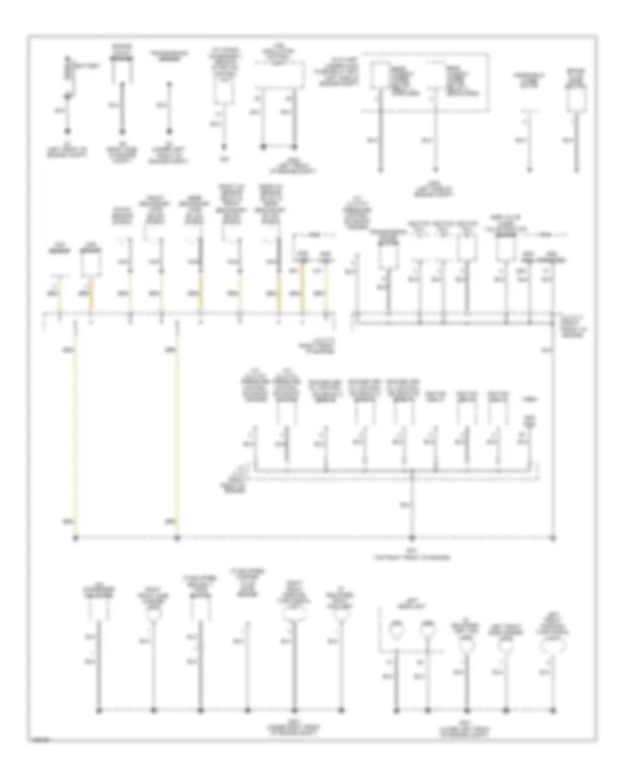
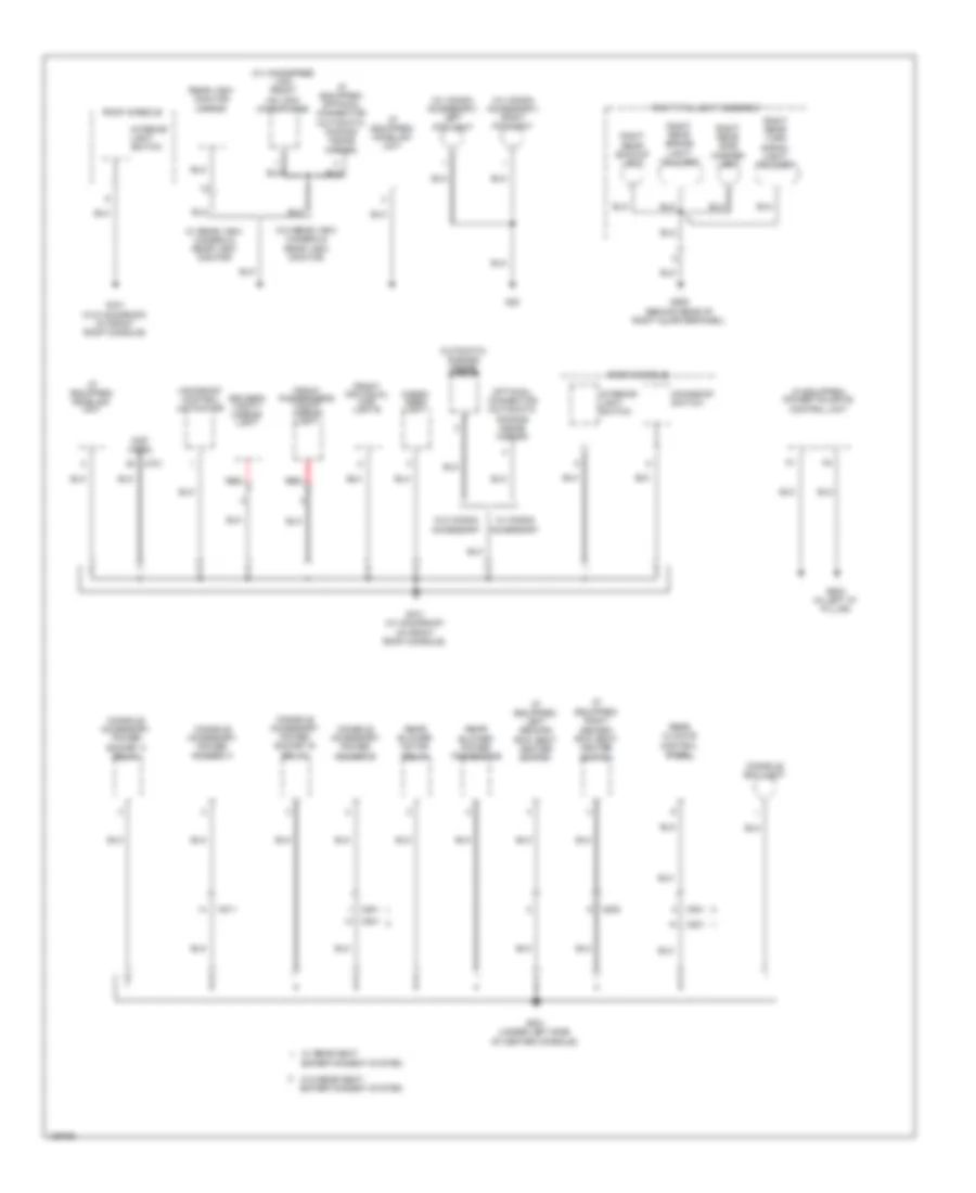
Ground Distribution Wiring Diagram (1 of 5) for Honda Pilot EX-L 2014
List of elements for Ground Distribution Wiring Diagram (1 of 5) for Honda Pilot EX-L 2014:
- (if equipped) left fog light
- (if equipped) right fog light
- (if equipped) security hood switch
- (if equipped) washer fluid level switch
- (lg1)
- (lg2)
- (pg1)
- (pg2)
- (pgmetcs)
- (top right front of engine)
- (w/ honda accessory) remote starting control unit
- A/c condenser fan motor
- A/t clutch pressure control solenoid valve a
- A/t clutch pressure control solenoid valve b
- A/t clutch pressure control solenoid valve c
- Auxiliary under-hood fuse/relay box (left side of engine compt)
- B40
- B41
- Battery
- Brake fluid level switch
- C41
- Ckp sensor
- Cmp sensor
- Egr valve & egr valve position sensor
- Engine mount bracket
- Front a/f sensor (b2,s1) & front secondary (b2,s2) shield
- Front secondary ho2s (b2,s2) shield
- G1 (left front of engine compt)
- G101
- G2 (right side of engine compt)
- G201 (under right front of engine compt)
- G3 (under left front of engine compt)
- G301 (lower left front of engine compt)
- G302 (left front of engine compt)
- G303 (left side of engine compt)
- G40
- Gnd
- High
- Ignition coil
- Ignition coil 1
- Ignition coil 2
- Ignition coil 3
- J/c c111 (right front of engine)
- J/c c112 (right front of engine)
- J/c c113 (right front of engine)
- Knock sensor shield
- Left front parking/ turn signal light
- Left front side marker light
- Left headlight
- Low
- Nca
- Pcm
- Rear a/f sensor (b1,s1) & rear secondary (b1,s2) shield
- Rear secondary ho2s (b1,s2) shield
- Rear window wiper motor relay 1 (forward)
- Rear window wiper motor relay 2 (backward)
- Right front parking/ turn signal light
- Right front side marker light
- Rocker arm oil control solenoid a (bank 1)
- Rocker arm oil control solenoid a (bank 2)
- Rocker arm oil control solenoid b (bank 1)
- Transmission housing
- Transmission range switch
- Vsa modulator- control unit
- Windshield wiper motor
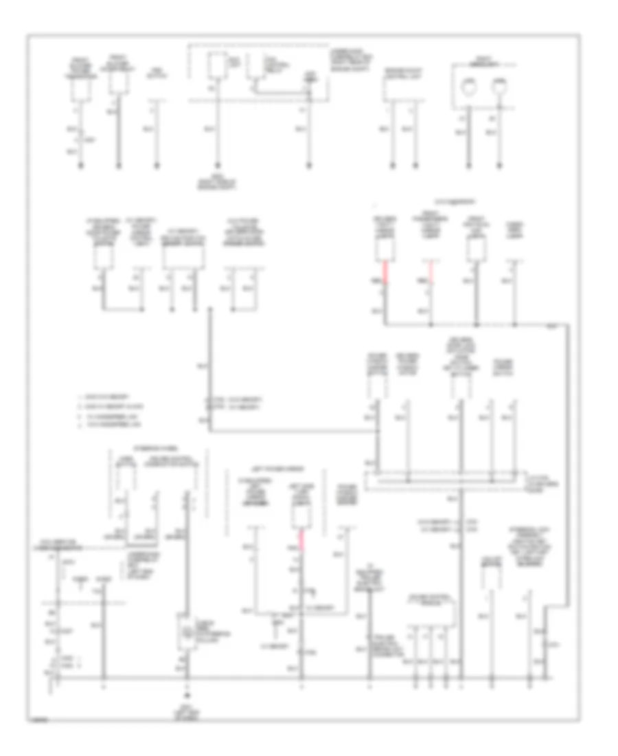
Ground Distribution Wiring Diagram (2 of 5) for Honda Pilot EX-L 2014
List of elements for Ground Distribution Wiring Diagram (2 of 5) for Honda Pilot EX-L 2014:
- (if equipped) driver's door power tailgate switch
- (if equipped) left power mirror defogger
- (if equipped) trailer electric brake unit
- (left end of dash)
- (not used)
- (right rear of
- (w/ memory)
- (w/ memory) power mirror control unit
- (w/o memory)
- (w/o moonroof)
- (w/o power tailgate) driver's door hatch glass opener switch
- 2wd w/ memory & 4wd
- 2wd w/o memory
- C12
- C307
- C351
- C402
- C701
- C751
- C752
- C753
- Cable reel (in steering column)
- Cargo area light
- Cruise control combination switch
- Driver's door lock actuator/ knob switch/ key cylinder switch
- Driver's power window motor
- Driver's vanity mirror light
- Driving position memory switch
- Eld unit
- Engine compt)
- Engine mount control unit
- Fan control relay
- Front blower motor relay
- Front blower power transistor
- Front individual map light
- Front passenger's vanity mirror light
- G202 (right side of engine compt)
- G401 (left end of dash)
- Gauge control module
- High
- Horn switch
- J/c c754 (in driver's door)
- Left power mirror
- Left side turn signal light
- Low
- Micu
- Micu service check connector
- Pnk
- Power mirror switch
- Power window master switch
- Psp switch
- Red
- Right headlight
- S-gnd
- Steering lock assembly (ignition key switch/ignition key light/key interlock solenoid)
- Steering wheel
- T34
- Trailer electric brake unit connector
- Under-dash fuse/relay box
- Under-hood fuse/relay box
- Vsa off switch
- W/ handsfree link
- W/ memory
- W/o handsfree link
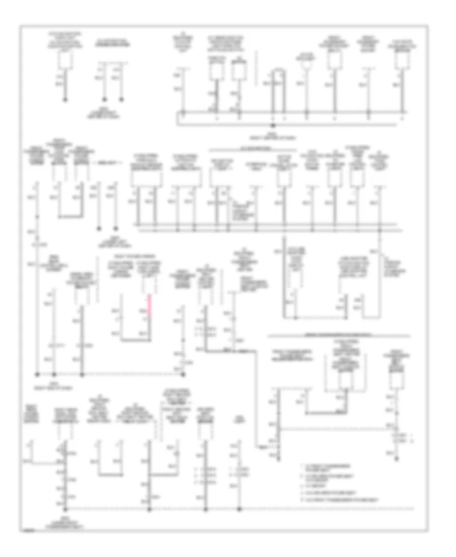
Ground Distribution Wiring Diagram (3 of 5) for Honda Pilot EX-L 2014
List of elements for Ground Distribution Wiring Diagram (3 of 5) for Honda Pilot EX-L 2014:
- (front passenger's power seat)
- (if equipped)
- (if equipped) ac inverter unit
- (if equipped) automatic lighting control unit
- (if equipped) climate control unit
- (if equipped) front passenger's seat heater
- (if equipped) hands free link control unit
- (if equipped) parking &
- (if equipped) right power mirror defogger
- (if equipped) right second row seat heater
- (if equipped) right second row seat heater relay (high)
- (if equipped) right second row seat heater relay (low)
- (if equipped) right side turn signal light
- (if equipped) seat heater control unit
- (if equipped) tpms control unit
- (res) rear controller & screen
- (usb adapter w/o navigation) audio display usb adapter control unit
- (w/ navigation)
- (w/ navigation) stereo amplifier
- (w/o navigation) audio switch panel
- (w/o navigation) audio unit (w/ navigation) audio-navigation unit
- (w/o usb adapter) audio hvac display unit
- A/t gear position indicator panel light/park pin switch/d3 switch
- A12
- A13
- A28
- A29
- A36
- Active noise cancellation unit
- Backup sensor control unit
- C303
- C512
- C513
- C521
- C541
- C711
- C761
- C781
- C782
- Cargo area accessory power socket relay
- D12
- D3 switch
- Dlc
- Driver's seat position sensor
- Front accessory power socket
- Front accessory power socket relay
- Front passenger's door lock actuator/ knob switch
- Front passenger's power seat adjustment switch
- Front passenger's power window motor
- Front passenger's power window switch
- Front passenger's seat belt buckle switch
- Front passenger's seat cushion heater
- Front passenger's seat heater
- G402 (under right center of dash)
- G403 (right center of dash)
- G404 (right end of dash)
- G405 (under left center of dash)
- G502 (under front passenger's seat)
- Glove box light
- Interface dial
- Navigation display unit
- Nca
- Ods unit
- Park pin switch
- Pnk
- Right power mirror
- Right rear door lock actuator/ knob switch
- Right rear power window switch
- Right second row seat back heater
- Srs unit
- W/ driver's power seat w/o memory
- W/ front passenger's power seat
- W/ memory
- W/ parking & back- up sensor system
- W/o driver's power seat
- W/o front passenger's power seat
- Yaw rate acceleration sensor
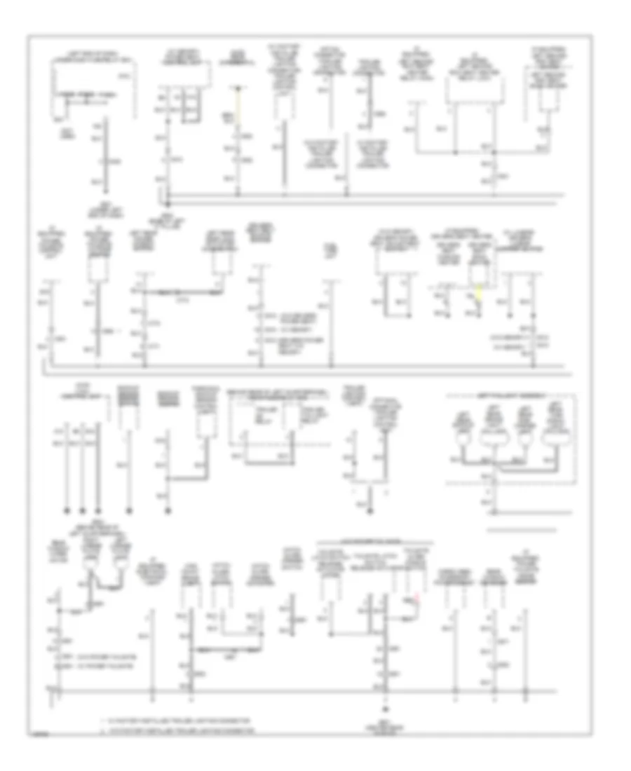
Ground Distribution Wiring Diagram (4 of 5) for Honda Pilot EX-L 2014
List of elements for Ground Distribution Wiring Diagram (4 of 5) for Honda Pilot EX-L 2014:
- (4wd) rear differential
- (4wd) vtm-4 control unit
- (behind rear of left quarterpanel) rear fuse/relay box
- (driver's power seat w/o memory)
- (if equipped)
- (if equipped) driver's seat heater
- (if equipped) electrical compass unit
- (if equipped) left second row seat heater
- (if equipped) left second row seat heater relay (low)
- (if equipped) power tailgate inside beeper
- (if equipped) power tailgate outside beeper
- (left end of dash) under-dash fuse/relay box
- (not used)
- (w/ factory installed trailer lighting connector) trailer lighting control unit
- (w/ lumbar) driver's lumbar support switch
- (w/ memory)
- (w/ memory) power seat control unit
- (w/ power tailgate)
- (w/o driver's power seat)
- (w/o memory)
- (w/o power tailgate)
- A10
- A18
- B12
- B19
- Backup sensor beeper
- Backup sensor beeper switch
- C308
- C501
- C512
- C552
- C553
- C562
- C601
- C602
- C651
- C661
- C671
- C771
- C772
- Cargo area accessory power socket
- Driver's power seat adjustment switch
- Driver's seat back heater
- Driver's seat belt buckle switch
- Driver's seat cushion heater
- E33
- F20
- Fuel tank unit
- G501 (under left end of dash)
- G503 (base of left "c" pillar)
- G504 (behind rear of left quarterpanel)
- G601 (center rear of roof)
- Hatch glass latch switch
- Hatch glass opener actuator
- Hatch glass opener switch
- High mount brake light
- Left license plate light
- Left rear backup light
- Left rear brake light/ taillight
- Left rear door lock actuator/ knob switch
- Left rear power window switch
- Left rear side marker light
- Left rear turn signal light/ taillight
- Left second row seat back heater
- Left second row seat heater relay (high)
- Left taillight assembly
- Micu
- Nca
- Option connector (trailer lighting connector)
- Optional connector (trailer lighting control unit)
- P-gnd
- Parking & backup sensor control unit
- Power tailgate control unit
- Rear window defogger
- Rear window wiper motor
- Red
- Right license plate light
- Tailgate latch switch release actuator diode
- Tailgate latch switch/ release actuator
- Tailgate outer handle switch
- Trailer ig2 relay
- Trailer lighting connector
- Trailer lighting control unit
- Trailer taillight relay
- W/ factory installed trailer lighting connector
- W/ factory-installed trailer lighting connector
- W/o factory installed trailer lighting connector
- W/o factory-installed trailer lighting connector
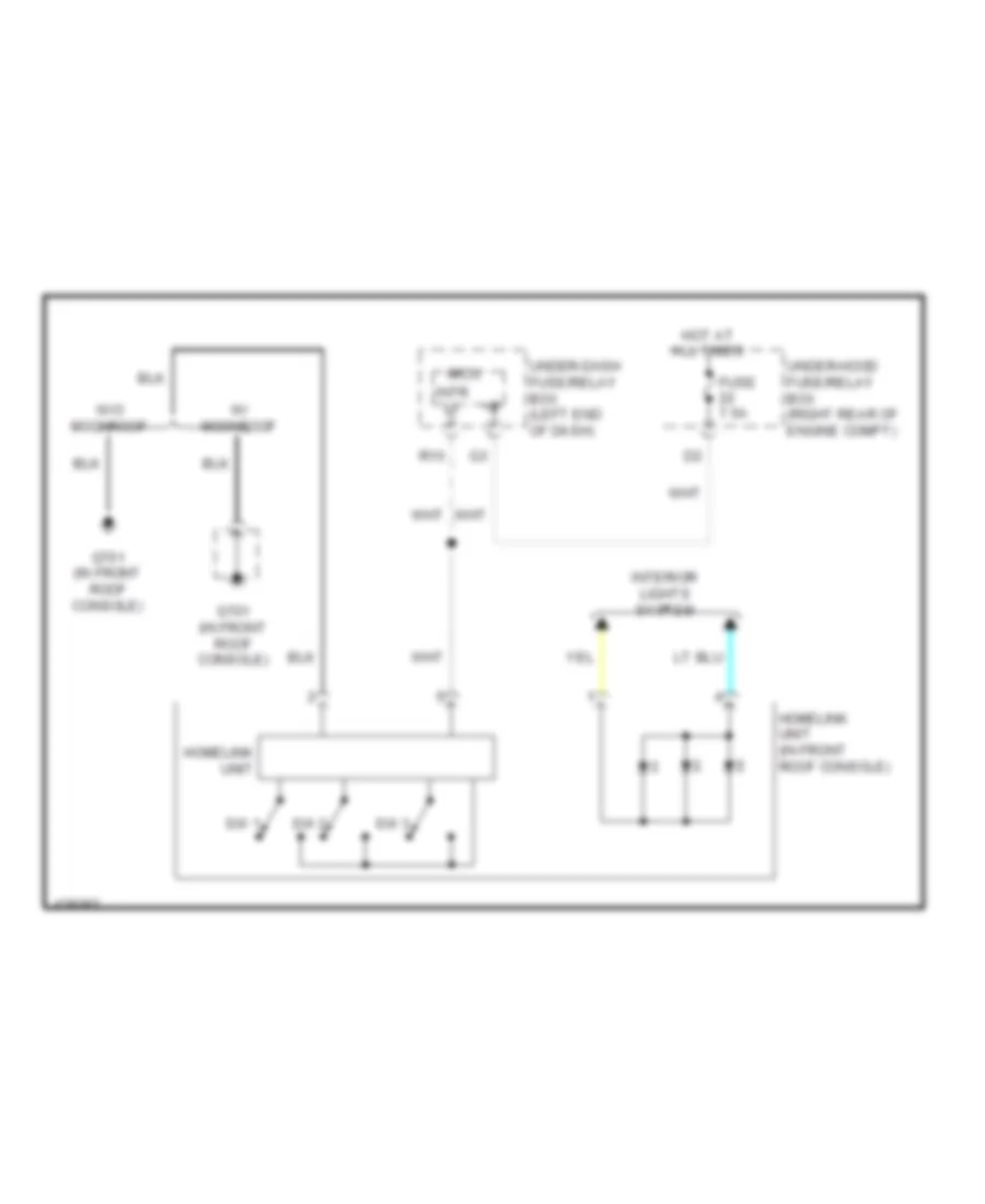
Ground Distribution Wiring Diagram (5 of 5) for Honda Pilot EX-L 2014
List of elements for Ground Distribution Wiring Diagram (5 of 5) for Honda Pilot EX-L 2014:
- (behind rear of right quarterpanel)
- (if
- (if equipped) homelink unit
- (if equipped) left second row seat heater switch
- (if equipped) optional connector (automatic dimming inside mirror)
- (if equipped) power tailgate control unit
- (not used)
- (w/ handsfree link) front hfl-anc microphone
- (w/ honda accessory) left fog light
- (w/ honda accessory) right fog light
- Automatic dimming inside mirror
- C701
- C801
- C802
- C811
- Cargo area light
- Console accessory power socket a
- Console accessory power socket a relay
- Console accessory power socket b
- Console accessory power socket b relay
- Console box light
- Driver's vanity mirror light
- Equipped) right second row seat heater switch
- Front individual map lights
- Front passenger's vanity mirror light
- G20
- G505
- G602 (in left "d" pillar)
- G701 (w/ moonroof) (in front roof console)
- G701 (w/o moonroof) (in front roof console)
- G801 (under left side of center console)
- Interior light switch
- Moonroof control unit/motor
- Moonroof switch
- Optional connector (automatic dimming inside mirror)
- Rear blower motor relay
- Rear blower power transistor
- Rear climate control panel
- Rear view monitor mirror
- Red
- Right rear backup light
- Right rear brake light/ taillight
- Right rear side marker light
- Right rear turn signal light/ taillight
- Right taillight assembly
- Roof console
- W/ honda accessory
- W/ rear seat entertainment system
- W/ rear view camera & rear view monitor
- W/o honda accessory
- W/o rear seat entertainment system
- W/o rear view camera & rear view monitor
HEADLIGHTS
Headlights Wiring Diagram (1 of 3) for Honda Pilot EX-L 2014
List of elements for Headlights Wiring Diagram (1 of 3) for Honda Pilot EX-L 2014:
- +b auto lt
- +b backup
- 0) off
- 1) on
- 10v stabilizer circuit
- 5v stabilizer circuit/controller area network controller
- B-can hi
- B-can lo
- Body controller area network transceiver
- C308
- C401
- Combination light switch
- Computer data lines system
- Dimmer sw
- Dimmer/ flash-to- pass switch 0) low 1) high 2) passing
- Dimming circuit
- Drl indicator (w/o multi- information switch
- F20
- Fog light ind
- Fog light switch
- Fr fog rly
- Fr fog sw
- Fuse 10a
- Fuse 7.5a
- G501 (under left end of dash)
- Gauge control module
- Gnd
- H/l off sw
- H/l on sw
- Headlight switch 0) off 1) park 2) auto 3) head
- High beam indicator
- Hot at all times
- Hot in on
- Hot in on or start
- Ig1 meter
- Ig2 day lt
- Indicator drive circuit
- Lights on indicator
- Micu
- P-gnd
- P10
- Passing sw
- Pnk
- Q10
- Red
- S11
- S12
- S13
- S14
- S15
- Small lt sw
- T12
- T29
- Under-dash fuse/relay box (left end of dash)
- W/ automatic lighting system
- W/ driver's lumbar support
Headlights Wiring Diagram (2 of 3) for Honda Pilot EX-L 2014
List of elements for Headlights Wiring Diagram (2 of 3) for Honda Pilot EX-L 2014:
- (optional connector)
- Automatic lighting control unit (if equipped) (under left side of dash)
- B-can hi
- B-can lo
- C201
- C303
- Computer data lines system
- Factory
- Fog light inline connector pnk
- Fog light relay (behind right kick panel)
- Fuse 10a
- Fuse 20a
- G20
- G201 (under right front of engine compt)
- G301 (lower left front of engine compt)
- G403 (right center of dash)
- Gnd1
- Gnd2
- H/l
- Honda accessory
- Hot at all times
- Ig1
- Left fog light
- Pnk
- Right fog light
- Sig
- Sio
- Sip
- Under-hood fuse/relay box (right rear of engine compt)
Headlights Wiring Diagram (3 of 3) for Honda Pilot EX-L 2014
List of elements for Headlights Wiring Diagram (3 of 3) for Honda Pilot EX-L 2014:
- (not used)
- Air conditioning system
- Automatic lighting sensor
- Automatic lighting sensor/ sunlight sensor (top center of dash)
- C201
- C307
- Driver's door switch (on left "b" pillar)
- Drl control circuit
- Drswdr
- E37
- F22
- Fuse 10a
- Fuse 15a
- Fuse 20a
- G15
- G17
- G202 (right side of engine compt)
- G301 (lower left front of engine compt)
- G401 (left end of dash)
- Headlight low beam relay
- Hot at all times
- Ig key sw
- Ignition key switch
- Instrument cluster system
- Left headlight
- Micu
- Parking brake switch (top of parking brake pedal assembly)
- R16
- Red
- Right headlight
- Steering lock assembly (ignition key switch/ ignition key light/ key interlock solenoid)
- Sunlight sensor
- Under-dash fuse/relay box (left end of dash)
HORN
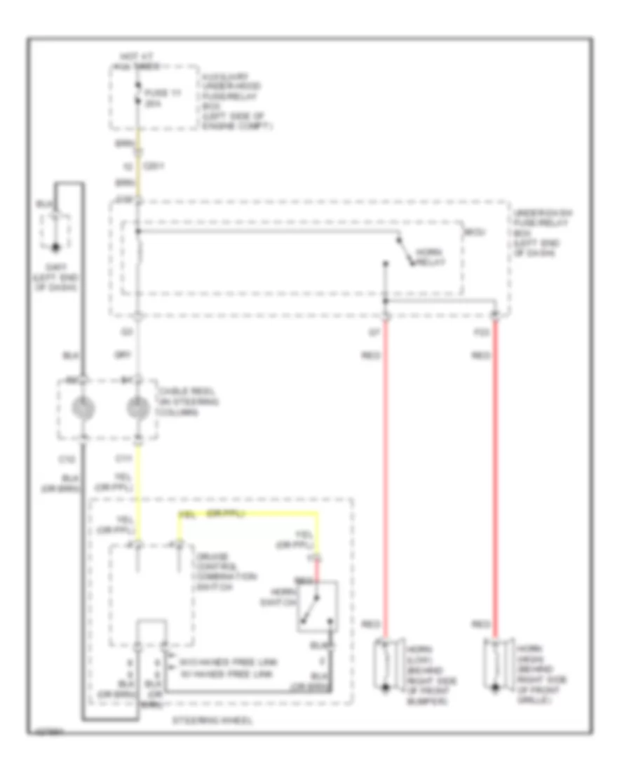
Horn Wiring Diagram for Honda Pilot EX-L 2014
List of elements for Horn Wiring Diagram for Honda Pilot EX-L 2014:
- Auxiliary under-hood fuse/relay box (left side of engine compt)
- C11
- C12
- C201
- Cable reel (in steering column)
- Cruise control combination switch
- F23
- Fuse 11 20a
- G16
- G401 (left end of dash)
- Horn (high) (behind right side of front grille)
- Horn (low) (behind right side of front bumper)
- Horn relay
- Horn switch
- Hot at all times
- Micu
- Red
- Steering wheel
- Under-dash fuse/relay box (left end of dash)
- W/ hands free link
- W/o hands free link
INSTRUMENT CLUSTER
Instrument Cluster Wiring Diagram (1 of 2) for Honda Pilot EX-L 2014
List of elements for Instrument Cluster Wiring Diagram (1 of 2) for Honda Pilot EX-L 2014:
- (4wd) a/t temperature ind
- (4wd) vtm-4 ind
- (except touring) low tire pressure ind
- (on driver's "b" pillar) driver's door switch
- (on left rear "c" pillar) left rear door switch
- (right front of engine) j/c c114
- 5v stabilizer circuit/controller area network controller
- A48
- A49
- Abs ind
- Audio navigation unit (w/ navigation)
- B-can hi
- B-can lo
- B16
- B17
- C11
- C16
- C17
- C22
- C306
- C307
- C401
- Cable reel (in steering column)
- Can h
- Can l
- Charging system ind
- Computer data lines system
- Cruise control ind
- Cruise control system
- Cruise main ind
- Door open ind
- Drl ind
- Drswas
- Drswdr
- Drswra
- Drswrd
- E17
- E37
- Eco ind
- Exterior lights system
- Fog light ind
- Front passenger's door switch (on front passenger's "b" pillar)
- Fuel gauge sending unit
- Fuel pump unit (in top of fuel tank)
- Fuse 7.5a
- G401 (left end of dash)
- Gauge control module
- Hot in on or start
- Ig1 meter
- Ill+
- Indicator drive circuit
- Interior lights system
- J/c c111 (right front of engine)
- Left turn signal ind
- Light control ind
- Lights on ind
- Low fuel ind
- Low oil
- Maintenance minder ind
- Message ind
- Micu
- Mil ind
- Multi- information switch
- Next switch
- P10
- Parking brake/ brake system ind
- Pcm (right side of engine compt)
- Pnk
- Power tailgate ind
- Pressure ind
- Red
- Ref vol
- Right rear door switch (on right rear "c" pillar)
- Right turn signal ind
- Rocker arm oil pressure sensor
- Seat belt reminder ind
- Select/ reset switch
- Side airbag off ind
- Snsr gnd
- Snsr input
- Srs ind
- Starter system ind
- Steering wheel
- T12
- T29
- To compulsory turning off circuit (diagram 2 of 2)
- To dimming circuit (diagram 2 of 2)
- To front parking sensor beeper (diagram 2 of 2)
- To pin 28 (diagram 2 of 2)
- Tpms ind
- Turn signal/hazard relay 2 (sounder)
- Under-dash fuse/relay box (left end of dash)
- Vsa off ind
- Vsa system ind
- W/o multi-information switch
- Washer fluid level ind
Instrument Cluster Wiring Diagram (2 of 2) for Honda Pilot EX-L 2014
List of elements for Instrument Cluster Wiring Diagram (2 of 2) for Honda Pilot EX-L 2014:
- -off circuit
- 10v stabilizer circuit
- 5v reg short
- 5v stabilizer circuit/controller area network controller
- A/t gear position dimming circuit
- A/t gear position indicator drive circuit
- A14
- B11
- Beeper
- Body controller area network transceiver
- Brake fluid level switch (on brake fluid reservoir)
- Brightening switch
- Brightness dimming circuit
- C203
- C303
- C401
- C402
- Cabaret (white) brightness control & dimming circuit
- Compulsory turning
- Compulsory turning -on circuit
- Control and
- Dial (white) brightness control & dimming circuit
- Dimming circuit
- Dimming switch
- Engine coolant temperature gauge
- Fail-safe circuit
- From eco ind (diagram 1 of 2)
- From left turn signal ind (diagram 1 of 2)
- From mil ind (diagram 1 of 2)
- From pin 16 (diagram 1 of 2)
- Front parking sensor beeper
- Fuel gauge
- Fuse 10a
- G201 (under right front of engine compt)
- G303 (left side of engine compt)
- G401 (left end of dash)
- Gauge control module
- High beam ind
- Hot at all times
- Immobilizer system ind
- Indicator drive circuit
- Information display (without multi-information switch) multi- information display (mid) unit (multi-information switch)
- Lcd (amber)
- Lcd (white) brightness control & dimming circuit
- Lcd back light
- Network transceiver fast controller area
- Odometer/trip/meter select/reset switch
- Parking brake switch (top of parking brake pedal assembly)
- Pnk
- Pointer (red) brightness control & dimming circuit
- Protect
- Rear parking/ backup sensor beeper
- Red
- Security ind
- Security ind blinking circuit
- Speedometer
- Tachometer
- Under-hood fuse/relay box (right rear of engine compt)
- Unit 5v control
- Vsa off switch
- Vtm-4 control unit (4wd) (behind rear of left quarterpanel)
- Washer fluid level switch (if equipped) (in washer fluid reservoir)
INTERIOR LIGHTS
Courtesy Lamps Wiring Diagram (1 of 3) for Honda Pilot EX-L 2014
List of elements for Courtesy Lamps Wiring Diagram (1 of 3) for Honda Pilot EX-L 2014:
- (ignition key switch/ ignition key light/ key interlock solenoid)
- C11
- C601
- C651
- C652
- C701
- C751
- Door
- Door lock knob
- Driver's door key cylinder switch
- Driver's door lock actuator/ knob switch/ key cylinder switch
- Driver's vanity mirror light
- Front individual map lights
- Front passenger's vanity mirror light
- Full
- Full latch switch
- Fuse 10a
- Fuse 7.5a
- G401 (left end of dash)
- G701 (in front roof console)
- Homelink unit (if equipped) (in front roof console)
- Hot at all times
- Ignition key light
- Ignition key switch
- Interior light switch
- J/c c754 (in driver's door)
- Key
- Left
- Lock
- Off
- Off door
- Pnk
- Power tailgate closer unit
- Power tailgate control unit (if equipped) (behind rear of left quarterpanel)
- Power tailgate latch/ratchet switch
- Rear individual map lights (2nd)
- Rear individual map lights (3rd)
- Red
- Right
- Roof console
- Seg3
- Steering lock assembly
- Under-hood fuse/relay box (right rear of engine compt)
- Unlock
- Visor open
- W/ memory
- W/ moonroof
- W/o memory
- W/o moonroof
Courtesy Lamps Wiring Diagram (2 of 3) for Honda Pilot EX-L 2014
List of elements for Courtesy Lamps Wiring Diagram (2 of 3) for Honda Pilot EX-L 2014:
- Active noise cancellation unit (w/ navigation) audio unit (w/o navigation) (active noise cancellation unit: under right front of center console)
- C402
- C501
- C601
- C652
- C701
- C751
- C753
- Cargo area light
- Cargo lt
- Door
- Driver's door courtesy light
- E16
- G401 (left end of dash)
- G701 (in front of roof console)
- Inr lt
- Inside tailgate switch (w/ power tailgate)
- Left running board led assembly 1
- Left running board led assembly 2
- Off
- Optional connector (left running board light)
- Optional connector (right running board light)
- Pnk
- Red
- Right running board led assembly 1
- Right running board led assembly 2
- W/ memory
- W/ moonroof
- W/ navigation
- W/o memory
- W/o moonroof
- W/o navigation
Courtesy Lamps Wiring Diagram (3 of 3) for Honda Pilot EX-L 2014
List of elements for Courtesy Lamps Wiring Diagram (3 of 3) for Honda Pilot EX-L 2014:
- (in steering column) immobilizer- keyless control unit
- (not used)
- +b backup
- +b intrlt
- Antenna
- As courtesy
- B-can hi
- B-can lo
- C306
- C307
- C501
- C601
- C651
- C751
- C761
- Cargo lt-
- Computer data lines system
- Door multiplex control unit
- Dr courtesy
- Driver's door switch (on driver's "b" pillar)
- Drswdr
- Drswra
- Drswrd
- Drwas
- E12
- E16
- E17
- E36
- E37
- E38
- Front passenger's door courtesy light
- Front passenger's door switch (on passenger's "b" pillar)
- Fuse 7.5a
- G/h sw
- G401 (left end
- G401 (left end of dash)
- G601 (center rear of roof)
- Hatch glass latch switch
- Hot in on or start
- Ig key sw
- Ig1 meter
- Intr lt-
- Left rear door switch (on left rear "c" pillar)
- Lock
- Micu
- Of dash)
- Pnk
- Power window master switch
- R10
- R16
- Red
- Right rear door switch (on right rear "c" pillar)
- S-gnd
- T/g sw
- T10
- T12
- T29
- T34
- Tailgate latch switch
- Tailgate latch switch/ release actuator (lower center of tailgate)
- Under-dash fuse/relay box (left end of dash)
- Unlock
- Vbu
- W/ memory
- W/ power tailgate
- W/o memory
- W/o power tailgate
Instrument Illumination Wiring Diagram (1 of 3) for Honda Pilot EX-L 2014
List of elements for Instrument Illumination Wiring Diagram (1 of 3) for Honda Pilot EX-L 2014:
- (if
- (left end of dash)
- (under left end of dash)
- +b backup
- Audio remote switch
- Auto
- B-can hi
- B-can lo
- B10
- C307
- C308
- C402
- Cable reel (in steering column)
- Combi gnd
- Combination light switch
- Computer data lines system
- Cruise control combination switch
- Equipped)
- F20
- Fuse 10 7.5a
- Fuse 10a
- G401
- G501
- H/l off sw
- H/l on
- Head
- Headlight switch
- Headlights
- Hfl switch (w/o navigation) hfl-navigation voice control switch (w/ navigation)
- Hot at all times
- Hot in on or start
- Ig1 meter
- Micu
- Multi- information switch
- Off
- P-gnd
- Park
- Pnk
- S-gnd
- S11
- S13
- Small lt sw
- Steering wheel
- System
- T12
- T29
- T34
- Under-dash fuse/relay box (left end of dash)
- Under-hood fuse/relay box (right rear of engine compt)
- W/ audio remote switch
- W/ automatic lighting
- W/ hands free link
- W/ memory
- W/o audio remote switch
- W/o memory
Instrument Illumination Wiring Diagram (2 of 3) for Honda Pilot EX-L 2014
List of elements for Instrument Illumination Wiring Diagram (2 of 3) for Honda Pilot EX-L 2014:
- (4wd)
- (if
- (left center of dash)
- (left center of dash) s1 (thermal cap)
- (thermal cap)
- (under left side of center console)
- (w/ res)
- (w/o res)
- A/t gear position indicator panel light
- A/t gear position indicator panel light/ park pin switch/d3 switch (park pin switch: base of shift lever assembly)
- A13
- Ambient light (console)
- Ambient light (pocket) (if equipped)
- Ambient light (roof)
- Audio switch panel (w/ res)
- Audio unit
- Audio- hvac display unit (w/o navigation)
- B12
- C452
- C454
- C701
- C701 c701
- C711
- C801
- C821
- Climate control unit (if equipped)
- Console box light
- Equipped)
- Front passenger's airbag cut-off indicator
- G403 (right center of dash)
- G801
- Glove box light
- Hazard warning switch
- Homelink unit (if equipped) (in front roof console)
- Left second row seat heater switch
- Moonroof switch (if equipped)
- Navigation switch panel (w/ navigation)
- Nca
- Parking & backup sensor switch (if equipped)
- Rear climate control panel
- Rear controller & screen (w/ res)
- Red
- Res auxiliary jack assembly
- Right second row seat heater switch
- Roof console
- S3 (thermal cap) (upper right center of dash)
- Vsa off switch
- Vtm-4 lock switch
- W/ moonroof
- W/o moonroof
Instrument Illumination Wiring Diagram (3 of 3) for Honda Pilot EX-L 2014
List of elements for Instrument Illumination Wiring Diagram (3 of 3) for Honda Pilot EX-L 2014:
- (base of left "c" pillar) g503
- (if equipped)
- (not used)
- (option connector)
- (under front passenger's seat) g502
- +b back- up
- 10v stabilizer circuit
- A/t gear position indicator
- A/t gear position indicator dimming circuit
- Area network controller 5v stabilizer circuit/controller
- B-can hi
- B-can lo
- Brightening switch
- C402
- C751
- C753
- C771
- C772
- C781
- C782
- Cabaret (white) brightness control & dimming circuit
- Computer data lines system
- Dial (white) brightness control & dimming circuit
- Dimming circuit
- Dimming switch
- Door multiplex control unit
- Driver's door hatch glass opener switch (w/o power tailgate)
- Driver's door power tailgate switch (w/ power tailgate)
- Driving position memory switch
- E25
- E26
- Fuse 14 7.5a
- Fuse 15a
- G401 (left end of dash)
- Gauge control module
- Hot at all times
- Ig1 meter
- Ill
- Ill+
- Ill-
- Indicator drive circuit
- J/c c754 (in driver's door)
- Lcd (white) brightness control & dimming circuit
- Lcd back light
- Left rear power window switch
- Light control indicator
- Lights on ind
- Micu
- P10
- Pointer (red) brightness control & dimming circuit
- Power mirror switch
- Power window master switch
- Q12
- Q13
- Red
- Right rear power window switch
- Taillight relay
- Transceiver area network controller body
- Under-dash fuse/relay box (left end of dash)
- W/ memory
- W/o memory
MEMORY SYSTEMS
Memory Mirrors Wiring Diagram (1 of 2) for Honda Pilot EX-L 2014
List of elements for Memory Mirrors Wiring Diagram (1 of 2) for Honda Pilot EX-L 2014:
- (in driver's door)
- (in driver's door) j/c c754
- (in steering column)
- (right rear of engine compt)
- +b backup
- +b mirror
- 5v stabilizer circuit/controller area network controller
- Antenna
- Atp-p
- B-can hi
- B-can lo
- B26
- B38
- B39
- B40
- Body controller area network transceiver
- C102
- C303
- C401
- C402
- C512
- C751
- C752
- C753
- Computer data lines system
- Door multiplex control unit
- Driving position memory switch
- Driving position memory switch lights
- Fuse 10a
- Fuse 7.5a
- G101 (top right front of engine)
- G401 (left end of dash)
- Gauge control module
- Gnd
- Hot at all times
- Hot in on
- Hot in on or start
- Ig1
- Illumi
- Immobilizer keyless control unit
- J/c c111 (right front of engine)
- Lmc
- Lmh
- Lmv
- Lseh
- Lsev
- Memo button
- Memo ind 1
- Memo ind 2
- Memo pos 1
- Memo pos 2
- Memo set
- Meter
- Micu
- Mldl
- Mldr
- Mrdl
- Mrdr
- Mul
- Multi-information display (mid) unit
- N11
- P10
- Pnk
- Pos 1 button
- Pos 1 ind
- Pos 2 button
- Pos 2 ind
- Power mirror control unit
- Power seat control unit (under driver's seat)
- Power window master switch
- Red
- Rmc
- Rmh
- Rmv
- Rseh
- Rsev
- Sen feed
- Shift interlock system
- T12
- T29
- Transmission range switch (bottom rear of transmission housing)
- Uart
- Under-dash fuse/relay box (left end of dash)
- Under-hood fuse/relay box
- Vbu
Memory Mirrors Wiring Diagram (2 of 2) for Honda Pilot EX-L 2014
List of elements for Memory Mirrors Wiring Diagram (2 of 2) for Honda Pilot EX-L 2014:
- C751
- C753
- C761
- Defogger
- Defogger system
- Down
- Exterior lights system
- G401 (left end of dash)
- Interior lights system
- Internal switch positions
- J/c c754 (in driver's door)
- Left
- Left power mirror
- Left side turn signal light
- Left/right motor
- Mirror direction selected
- Pnk
- Power mirror switch
- Red
- Right
- Right power mirror
- Right side turn signal light
- Swing
- Switch 1
- Switch 2
- Switch 3
- Tilt
- Up/down motor
Memory Seat Wiring Diagram (1 of 2) for Honda Pilot EX-L 2014
List of elements for Memory Seat Wiring Diagram (1 of 2) for Honda Pilot EX-L 2014:
- (right rear of engine compt)
- +b backup
- A10
- A11
- A12
- A13
- A14
- A15
- A16
- A17
- A18
- Atp-p
- Auxiliary under-hood fuse/relay box (left side of engine compt)
- B-can hi
- B-can lo
- B10
- B11
- B12
- B13
- B14
- B15
- B16
- B17
- B18
- B19
- B20
- B21
- B22
- B23
- B24
- B25
- B26
- B27
- B28
- B29
- B30
- B31
- B32
- B33
- B34
- B35
- B36
- B37
- B38
- B39
- B40
- C102
- C206
- C303
- C308
- C402
- C512
- Computer data lines system
- Driver's
- Driver's power seat front up-down motor/position sensor (under right side of driver's seat)
- Driver's power seat rear up-down motor/position sensor (under right side of driver's seat)
- Driver's power seat recline motor/position sensor (under right side of driver's seat)
- Driver's power seat slide motor/position sensor (under right side of driver's seat)
- E28
- F20
- Fhdn
- Fhm(+)
- Fhm(-)
- Fhse
- Fhup
- Fuse 10a
- Fuse 20a
- Fuse 7.5a
- G401 (left end of dash)
- G501 (under
- G503 (base of left "c" pillar)
- Gnd
- Hot at all times
- Hot in on
- Hot in on or start
- Ig1
- Ig1 meter
- Left end of dash)
- Micu
- Motor connector
- N11
- Out- put
- P- gnd
- Pg1
- Pg2
- Pnk
- Power seat control unit (under driver's seat)
- Rebw
- Red
- Ref- volt
- Refw
- Rem(+)
- Rem(-)
- Rese
- Rhdn
- Rhm(+)
- Rhm(-)
- Rhse
- Rhup
- S- gnd
- Scom
- Seg
- Shift interlock system
- Slbw
- Slfw
- Slm(+)
- Slm(-)
- Slse
- Svcc
- T34
- Uart
- Under-dash fuse/relay box (left end of dash)
- Under-hood fuse/relay box
- Vbu
- Vmp1
- Vmp2
Memory Seat Wiring Diagram (2 of 2) for Honda Pilot EX-L 2014
List of elements for Memory Seat Wiring Diagram (2 of 2) for Honda Pilot EX-L 2014:
- B-can hi
- B-can lo
- Bwd
- C401
- C752
- C753
- Computer data lines system
- Door multiplex control unit
- Down
- Driver's power seat adjustment switch
- Driving position memory switch
- Driving position memory switch lights
- Front up-down switch
- Fwd
- G101 (top right front of engine)
- G401 (left end of dash)
- Ig2
- Illumi
- J/c c111 (right front of engine)
- J/c c754 (in driver's door)
- Memo button
- Memo ind 1
- Memo ind 2
- Memo pos 1
- Memo pos 2
- Memo set
- Pnk
- Position 1 button
- Position 1 ind
- Position 2 button
- Position 2 ind
- Power mirror control unit (in driver's door)
- Power window master switch
- Rear up-down switch
- Recline switch
- Red
- Slide switch
- Transmission range switch (bottom range of transmission housing)
- Uart
- Vbu
- Vmp dr
NAVIGATION
Compass Wiring Diagram for Honda Pilot EX-L 2014
List of elements for Compass Wiring Diagram for Honda Pilot EX-L 2014:
- A12
- Audio unit
- C404
- C503
- Compass rx+
- Compass rx-
- Compass tx+
- Compass tx-
- D11
- D12
- E28
- Electrical compass unit (center rear of roof)
- Fuse 10 7.5a
- G402 (under right center of dash)
- G601 (center rear of roof)
- Gnd
- Hot in on or start
- Ig1
- Rx+
- Rx-
- Tx+
- Tx-
- Under-dash fuse/relay box (left end of dash)
- W/ usb adapter & power tailgate
- W/ usb adapter & w/o power tailgate
- W/ usb adapter & w/o xm radio
- W/ usb adapter & xm radio
- W/o usb adapter
Home Link Remote Control Wiring Diagram for Honda Pilot EX-L 2014
List of elements for Home Link Remote Control Wiring Diagram for Honda Pilot EX-L 2014:
- Fuse 7.5a
- G701 (in front roof console)
- Homelink unit
- Homelink unit (in front roof console)
- Hot at all times
- Interior lights system
- Intr lt
- Micu
- R10
- Sw 1
- Sw 2
- Sw 3
- Under-dash fuse/relay box (left end of dash)
- Under-hood fuse/relay box (right rear of engine compt)
- W/ moonroof
- W/o moonroof
Navigation Wiring Diagram (1 of 6) for Honda Pilot EX-L 2014
List of elements for Navigation Wiring Diagram (1 of 6) for Honda Pilot EX-L 2014:
- (not used)
- 10 speakers
- A10
- A11
- A12
- A13
- A14
- A15
- A16
- A17
- A18
- A19
- A20
- A21
- A22
- A23
- A24
- Acc
- Am/fm antenna amplifier
- Ant +b
- Audio navigation unit
- Aux det
- Aux gnd
- Aux l
- Aux r
- Aux s gnd
- Aux sh
- Aux sh gnd
- Backup
- C305
- C308
- C401
- C454
- C711
- C811
- C901
- Computer data lines system
- Ctr pre+
- Ctr pre-
- D10
- D11
- D12
- D13
- D14
- D15
- D16
- D17
- D18
- D19
- D20
- D21
- D22
- D23
- D24
- E22
- Fl pre+
- Fl pre-
- Fr pre+
- Fr pre-
- Fuse 17 20a
- Fuse 23 10a
- Fuse 30a
- Fuse 35 10a
- G402 (under right center of dash)
- Gnd
- Hot at all times
- Hot in acc or on
- K line
- Lt- intr
- Micu
- Nca
- Pnk
- Q14
- Red
- Remote
- Remote gnd
- Rf in
- Rf sh
- Right quarter glass
- Rl pre+
- Rl pre-
- Rr pre+
- Rr pre-
- Scty
- Sub pre +
- Sub pre -
- Swd +b
- Telm sig+
- Telm sig-
- Under-dash fuse/relay box (left end of dash)
- Under-hood fuse/relay box (right rear of engine compt)
- Usb adapter holder/auxiliary jack assembly
- Vsp
- Window antenna (am/fm)
Navigation Wiring Diagram (2 of 6) for Honda Pilot EX-L 2014
List of elements for Navigation Wiring Diagram (2 of 6) for Honda Pilot EX-L 2014:
- (10 speakers) front center speaker
- (10 speakers) left satellite speaker
- (10 speakers) right satellite speaker
- (left center of dash)
- 10 speakers
- Audio remote switch
- C401
- C403
- C404
- C503
- C752
- C761
- C771
- Cable reel (in steering column)
- Channel down switch
- Channel up switch
- Driver's door speaker
- Except 10 speakers
- Front passenger's door speaker
- Interior lights system
- J/c c423
- Left rear door speaker
- Left tweeter
- Mode switch
- Pnk
- Red
- Right tweeter
- Steering wheel
- Subwoofer
- To hfl-voice control switch (diagram 6 of 6)
- Volume down switch
- Volume up switch
Navigation Wiring Diagram (3 of 6) for Honda Pilot EX-L 2014
List of elements for Navigation Wiring Diagram (3 of 6) for Honda Pilot EX-L 2014:
- (10 speakers) left tweeter
- (10 speakers) right tweeter
- (right end of dash) stereo amplifier
- +b main
- +b sub
- A10
- A11
- A12
- A13
- A14
- A15
- A16
- A17
- A18
- A19
- A20
- A21
- A22
- A23
- A24
- Anc f-
- Anc fr+
- Anc r-
- Anc wr+
- Audio navigation unit
- B10
- B11
- B12
- B13
- B14
- B15
- B16
- B17
- B18
- B19
- B20
- B21
- B22
- B23
- B24
- B25
- B26
- B27
- B28
- Bus sh
- Bush sh
- C403
- C452
- C711
- C781
- Ctr pre -
- Ctr pre+
- Ctr sp+
- Ctr sp-
- F1 rr aux
- F10
- F11
- F12
- F13
- F14
- F15
- F16
- Fl pre+
- Fl pre-
- Fl sp+
- Fl sp-
- Fl tw+
- Fl tw-
- Fr pre+
- Fr pre-
- Fr sp+
- Fr sp-
- Fr tw+
- Fr tw-
- G402 (under right center of dash)
- G404 (right end of dash)
- Gnd
- Gnd main
- Gnd sub
- Hp l
- Hp r
- Hp r/l gnd
- Hp r/l sh
- Ill+
- Ill-
- Interior lights system
- Nca
- Pnk
- R/l gnd
- R/l sh
- Rear controller & screen
- Red
- Res
- Rg gnd
- Rg l+
- Right rear door speaker
- Rl pre in-
- Rl pre+
- Rl sp+
- Rl sp-
- Rl srsp+
- Rl srsp-
- Rr aux hp l
- Rr aux hp r
- Rr aux video
- Rr bus+
- Rr bus-
- Rr ntsc
- Rr ntsc gnd
- Rr ntsc sh
- Rr pre+
- Rr pre-
- Rr sp+
- Rr sp-
- Rr srsp+
- Rr srsp-
- Rs 485+
- Rs 485-
- Satellite signal antenna
- Scty
- Subw pre+
- Subw pre-
- Subw+
- Subw-
- Swd +b
- Sys acc
- Video sh
- Xm antenna
Navigation Wiring Diagram (4 of 6) for Honda Pilot EX-L 2014
List of elements for Navigation Wiring Diagram (4 of 6) for Honda Pilot EX-L 2014:
- (behind rear of left quarterpanel) (4wd) vtm-4 control unit
- (near roof cargo area light) rear active noise cancellation microphone
- (right side of engine compt) pcm
- (under right front of center console) active noise cancellation unit
- A1 +b
- A10 ga-net bus-
- A11 gnd
- A12
- A13 aud r-
- A14
- A14 ga- audio l-
- A15
- A2 syc acc
- A3 ga-bus sh
- A30
- A33
- A4 aud sh
- A5 aud r+
- A6 aud l+
- A9 ga-net bus+
- Acc
- Anc chk2
- Anc f+
- Anc f-
- Anc r+
- Anc r-
- Anc sh
- B1 sat/ter
- B2 gnd sh
- C201
- C206
- C303
- C404
- C701
- Cargo lt
- Cssama
- Cssamc
- F mic +
- F mic sh
- Front hfl- navigation anc microphone
- G403 (right center of dash)
- Ga audio sw
- Ga- audio l+
- Ga- audio l-
- Ga- audio r+
- Ga- audio r-
- Ga-net bus +
- Ga-net bus -
- Ga-net bus sh
- Gnd
- Handsfree link control unit (if equipped) (under right front of center console)
- Hfl mute
- Hfl strg sw
- Interior lights system
- Intr lt
- J/c c425 (behind glove box)
- Mic +
- Mic -
- Mic sh
- Mic sig+
- Mic sig-
- Mic+
- Mic-
- Nca
- Nep
- Pnk
- R mic +
- R mic sh
- R mic+
- Red
- Sw +b
- Telm sig +
- Telm sig -
- Telm sig sh
- Vss out
- Xm receiver (behind front of right quarterpanel)
Navigation Wiring Diagram (5 of 6) for Honda Pilot EX-L 2014
List of elements for Navigation Wiring Diagram (5 of 6) for Honda Pilot EX-L 2014:
- (behind middle of dash) j/c c426
- Audio l+
- Audio l-
- Audio navigation unit
- Audio r+
- Audio r-
- Audio sh
- B-can h
- B-can l
- C10
- C11
- C12
- C13
- C14
- C452
- C801
- Computer data lines system
- E10
- E11
- E12
- E13
- E14
- E15
- E16
- E17
- E18
- E19
- E20
- Ga-net bus sh
- Ga-net bus+
- Ga-net bus-
- Gnd
- Ill+
- Ill-
- Interior lights system
- Nca
- Nca usb data+
- Nca usb data-
- Nca usb gnd
- Nca usb vbus
- Red
- Res auxiliary jack assembly
- Rg gnd
- Rg l+
- Rg sh
- Rr aux audio gnd
- Rr aux audio l
- Rr aux audio r
- Rr aux audio sh
- Rr aux det
- Rr aux hpl
- Rr aux hpr
- Rr aux r/l gnd
- Rr aux r/l sh
- Rr aux video
- Rr aux video gnd
- Rr aux video sh
- Rs 485 sh
- Rs 485+
- Rs 485-
- Syc acc
- Usb adapter holder/auxillary jack assembly
- Usb data+
- Usb data-
- Usb det
- Usb det gnd
- Usb gnd
- Usb main har- ness connector
- Usb port
- Usb sh
- Usb sub- harness connector
- Usb vbus
Navigation Wiring Diagram (6 of 6) for Honda Pilot EX-L 2014
List of elements for Navigation Wiring Diagram (6 of 6) for Honda Pilot EX-L 2014:
- (usa) rds-tmc antenna amplifier
- Acc
- Amplifier
- Anc chk2
- Audio navigation unit
- B-can h
- B-can l
- B-sig
- B10
- B11
- B12
- B13
- B14
- B15
- B16
- B17
- B18
- B19
- B20
- B21
- B22
- B23
- B24
- B25
- B26
- B27
- B28
- Back lt-
- Back switch
- C-sig
- C452
- C902
- Cable reel (in steering column)
- Cam adpt
- Cam bit0
- Cam bit1
- Cam gnd
- Cam sh
- Cam v
- Cam vgnd
- Computer data lines system
- Diag +
- Diag -
- From audio remote switch (diagram 2 of 6)
- G-sig
- G403 (right center of dash)
- Ga bus sh
- Ga net bus -
- Ga-net bus +
- Gnd
- Gps antenna
- Gps sh gnd
- Gps sig
- Hang up switch
- Hfl-navigation voice control switch
- Ill +
- Ill+
- Ill-
- Interface dial
- Interior lights system
- Jog
- Left quarter glass
- Mic sh
- Mic+
- Mic-
- Navigation display unit
- Navigation service check connector (behind right kick panel)
- Navigation service check connector (behind right kick panel) exterior lights system
- Navigation switch panel
- Navigation system
- Nca
- Pick up switch
- Pnk
- R-sig
- Red
- Rr aux audio gnd
- Rr aux audio l
- Rr aux audio r
- Rr aux audio sh
- Rr aux det
- Sh jog
- Sig gnd
- Sig sh
- Steering wheel
- Talk switch
- Tmc ant +b
- Tmc rf in
- Tmc rf sh
- Vcc
- W/ parking & backup sensor system
- Window antenna (rds/tmc)
Parking Assistant Wiring Diagram, Except Honda Accessory for Honda Pilot EX-L 2014
List of elements for Parking Assistant Wiring Diagram, Except Honda Accessory for Honda Pilot EX-L 2014:
- 5v stabilizer circuit/controller area network controller
- A16
- A48
- A49
- Atp-p
- Atp-r
- Atpp
- Atpr
- B-can
- B-can hi
- B-can lo
- Bdf
- Bdf side r
- Bor ctrl
- C102
- C201
- C203
- C25
- C402
- C562
- C563
- Can h
- Can l
- Computer data lines system
- E1 side r
- E2 ctrl
- F27
- Frl +
- Frl gnd
- Frl sig
- Front parking sensor beeper
- Fuse 23 10a
- Fuse 8 7.5a
- G101 (top right front of engine)
- G401 (left end of dash)
- G403 (right center of dash)
- Gauge control module
- Gnd
- Hi b-can lo
- Hot at all times
- Hot in on or start
- Ig1
- Ind
- Interior lights system
- J/c c111 (right front of engine)
- J/c c113 (right front of engine)
- Left front corner sensor (behind left side of front bumper)
- Left rear center sensor
- Left rear corner sensor (behind left corner of rear bumper)
- Main sw
- Micu
- Multi-information display (mid) unit multi-information switch
- Network transceiver fast controller area
- Parking & backup sensor control unit (left side of dash)
- Parking & backup sensor switch
- Parking/ backup sensor on indicator
- Pcm (right side of engine compt)
- Pnk
- Rear parking/ backup sensor beeper
- Red
- Right front corner sensor (behind right side of front bumper)
- Right rear center sensor
- Right rear corner sensor (behind right corner of rear bumper)
- Rrl +
- Rrl gnd
- Rrl sig
- Rrr +
- Rrr ctr +
- Rrr ctr gnd
- Rrr ctr sig
- Rrr gnd
- Rrr sig
- Sof
- Sof side r
- Sor ctrl
- T12
- T29
- Transmission range switch (bottom rear of transmission housing)
- Under-dash fuse/relay box (left end of dash)
- Under-hood fuse/relay box (right rear of engine compt)
- W/ factory installed trailer lighting connector
Parking Assistant Wiring Diagram, Honda Accessory for Honda Pilot EX-L 2014
List of elements for Parking Assistant Wiring Diagram, Honda Accessory for Honda Pilot EX-L 2014:
- (option connector)
- A/t reverse relay
- Back lt out
- Backup sensor beeper
- Backup sensor beeper switch
- Backup sensor control unit
- Backup sensor in-line fuse
- Backup sensor system connector
- Backup sensor system junction connector
- Beeper (+)
- C102
- C501
- E15
- Exterior lights system
- Fuse 10 7.5a
- G101 (top right front of engine)
- G504 (behind rear of left quarterpanel)
- Ground
- Hot in on or start
- J/c c111 (right front of engine)
- J/c c113 (right front of engine)
- Left center backup sensor
- Left corner backup sensor
- Micu
- Nca
- On indicator
- Pnk
- Red
- Right center backup sensor
- Right corner backup sensor
- Rr back sensor l
- Rr back sensor r
- Rr c/sensor l
- Rr c/sensor r
- Rr sens
- Transmission range switch (bottom rear of transmission housing)
- Under-dash fuse/relay box (left end of dash)
Rear Camera Wiring Diagram, with Navigation for Honda Pilot EX-L 2014
List of elements for Rear Camera Wiring Diagram, with Navigation for Honda Pilot EX-L 2014:
- Adapt
- Bit 0
- C404
- C503
- C601
- C651
- Cam adapt
- Cam gnd
- Cam v gnd
- Camera bit 0
- Camera bit 1
- Camera shield
- Camera vcc
- Camera video
- Fuse 23 10a
- G403 (right center of dash)
- Gnd
- Hot at all times
- Navigation display unit
- Nca bit 1 cam
- Nca cam
- Nca cam adapt
- Nca cam bit 0
- Nca cam bit 1
- Nca cam gnd
- Nca cam sh
- Nca cam v
- Nca cam v gnd
- Nca cam vcc
- Nca cam video
- Rearview camera (right side of tailgate)
- Red
- Under-hood fuse/relay box (right rear of engine compt)
Rear Camera Wiring Diagram, without Navigation for Honda Pilot EX-L 2014
List of elements for Rear Camera Wiring Diagram, without Navigation for Honda Pilot EX-L 2014:
- A10
- A17
- A20
- A21
- A25
- A26
- A27
- A28
- Adapt cam
- Audio display usb adapter control unit
- Bkup
- C404
- C503
- C601
- C651
- Cam adapt
- Cam gnd
- Cam v gnd
- Cam vcc
- Cam video
- Camera shield
- Camera vcc
- Camera video
- Can high
- Can low
- Computer data lines system
- Fuse 23 10a
- G403 (right center of dash)
- Gnd
- Gnd cam v
- Hot at all times
- Micu
- Pnk
- Rearview camera (right side of tailgate)
- Red
- Sh cam
- Under-dash fuse/ relay box (left end of dash)
- Under-hood fuse/relay box (right rear of engine compt)
- W/ power tailgate
- W/ xm radio
- W/o power tailgate
- W/o xm radio
POWER DISTRIBUTION
Power Distribution Wiring Diagram (1 of 9) for Honda Pilot EX-L 2014
List of elements for Power Distribution Wiring Diagram (1 of 9) for Honda Pilot EX-L 2014:
- (diagram 2 of 9)
- (not
- (not used)
- (right rear of engine compt) under-hood fuse/relay box
- 120a
- 30a
- 40a
- 50a
- 80a
- A/c compressor clutch relay
- A/c condenser fan diode
- A/c condenser fan relay
- A24
- A40
- Acm control relay
- Alternator
- Audio unit (w/o navigation) audio-navigation unit (w/ navigation)
- Battery
- C102
- C305
- C306
- E10
- Eld unit
- Etcs control relay
- Evap canister vent shut valve
- F13
- F16
- F18
- F19
- Fog light relay (if equipped)
- From eld unit (diagram 1 of 9)
- From fuse 17 (diagram 1 of 9)
- Front a/f sensor (b2,s1)
- Front blower motor relay
- Front passenger's power seat adjustment switch (if equipped)
- Front secondary (h02s) (b2,s2)
- Fuse 10 20a
- Fuse 11 15a
- Fuse 12 10a
- Fuse 15 7.5a
- Fuse 17 20a
- Fuse 18 15a
- Fuse 19 15a
- Fuse 20 7.5a
- Fuse 20a
- Fuse 21 15a
- Fuse 5
- Fuse 6 30a
- Fuse 7 30a
- Fuse 8 30a
- Fuse 9
- Fuse/relay box
- G1 (left front of engine compt)
- G18
- G19
- G20
- G21
- Ignition coil relay
- J/c c112 (right front of engine)
- Multi- fuse 1
- Multi- fuse 3
- Multi-fuse 2
- Multi-fuse 4
- Pcm
- Pgm-fi main relay 1
- Pgm-fi sub-relay
- Pnk
- Radiator fan relay
- Rear a/f sensor (b1,s1)
- Rear secondary (h02s) (b1,s2)
- Rear window defogger relay
- Starter
- Starter solenoid
- T101
- To ac inverter unit (diagram 3 of 9)
- To auxiliary under-hood
- To fuse 11 (diagram 1 of 9)
- To fuse 20 (diagram 5 of 9)
- To fuse 22 (diagram 4 of 9)
- To fuse 24 (diagram 5 of 9)
- To fuse 5 (diagram 5 of 9)
- To fuse 6 (diagram 1 of 9)
- To under-dash fuse/relay box (diagram 6 of 9)
- Under-dash fuse/relay box (left end of dash)
- Used)
Power Distribution Wiring Diagram (2 of 9) for Honda Pilot EX-L 2014
List of elements for Power Distribution Wiring Diagram (2 of 9) for Honda Pilot EX-L 2014:
- (left side of engine compt) auxiliary under-hood fuse/relay box
- (not used) (w/o ac power outlet)
- (under left front of center console)
- (w/ res)
- (w/o res)
- 20a
- B12
- C201
- C205
- C206
- C207
- C208
- C303
- C451
- C454
- C501
- C502
- C503
- C512
- C801
- C801 (w/o res)
- C811
- Cargo area accessory power socket
- Cargo area accessory power socket relay (behind right kick panel)
- Console accessory power socket a
- Console accessory power socket a relay
- Console accessory power socket b
- Console accessory power socket b relay (under left front of center console)
- Driver's power seat adjustment switch (if equipped)
- From battery a (diagram 1 of 9)
- From under-dash fuse/relay box (diagram 8 of 9)
- From under-dash w fuse/relay box (diagram 8 of 9)
- Front accessory power socket
- Front accessory power socket relay (left center of dash)
- Fuse
- Fuse 15a
- Fuse 20a
- Fuse 20a (4wd)
- Fuse 30a
- Fuse 40a
- G403 (right center of dash)
- G404 (right end of dash)
- G601 (center rear of roof)
- G801 (under left side of center console)
- Option connector (trailer lighting connector)
- Pnk
- Power seat control unit
- Power seat control unit (w/ driver's power seat)
- Power tailgate control unit (if equipped)
- Rear blower motor relay
- Rear fuse/relay box (behind rear of left quarterpanel)
- To fuse 3 (diagram 3 of 9)
- Trailer electric brake connector
- Trailer electric brake connector (if equipped)
- Trailer ig2 relay
- Vtm-4 relay (4wd)
- W/ factory-installed trailer lighting connector
- W/ memory
- W/ power tailgate
- W/o factory-installed trailer lighting connector
- W/o memory
- W/o power tailgate
Power Distribution Wiring Diagram (3 of 9) for Honda Pilot EX-L 2014
List of elements for Power Distribution Wiring Diagram (3 of 9) for Honda Pilot EX-L 2014:
- (if equipped)
- (left side of engine compt)
- (not used)
- 20a
- 7.5a
- Ac inverter unit (under right front of center console)
- Ac+
- Ac-
- Auxiliary under-hood fuse/relay box
- C206
- C207
- C454
- C531
- C541
- C811
- Cpu
- From fuse 17 (diagram 2 of 9)
- From s4 (thermal cap) (diagram 9 of 9)
- From under-hood fuse/relay box (diagram 1 of 9)
- Fuse (not used)
- Fuse 1
- Fuse 10a
- Fuse 15a
- Fuse 2
- Fuse 3
- Fuse 30a
- Fuse 4
- Fuse 40a
- G403 (right center of dash)
- Inverter
- Left second row seat heater relay (high)
- Left second row seat heater relay (low)
- Lighting connector
- Option connector (trailer lighting control unit)
- Pnk
- Power outlet
- Rear fuse/relay box (behind rear of left quarterpanel)
- Rear window wiper motor relay 1 (forward)
- Rear window wiper motor relay 2 (backward)
- Red
- Right second row seat heater relay (high)
- Right second row seat heater relay (low)
- To fuse 7 (diagram 4 of 9)
- Trailer lighting control unit
- Trailer taillight relay
- Vsa modulator control unit
- W/ factory-installed trailer lighting connector
- W/o factory-installed trailer
Power Distribution Wiring Diagram (4 of 9) for Honda Pilot EX-L 2014
List of elements for Power Distribution Wiring Diagram (4 of 9) for Honda Pilot EX-L 2014:
- (left end of dash) under-dash fuse/relay box
- (left side of engine compt) auxiliary under-hood fuse/relay box
- (not used) (w/o ac power outlet)
- (right rear of engine compt)
- (w/ c751 memory) c751 (w/o memory)
- (w/o moonroof) c701
- +b stop & horn
- 2wd w/ memory & 4wd 2wd w/o memory
- A17
- Active noise cancellation unit (w/ navigation)
- Audio display-usb adapter
- Audio-hvac display unit (w/o usb adapter)
- B11
- B36
- Backup
- Brake pedal position switch
- C201
- C206
- C307
- C402
- C451
- C501
- C512
- C601
- C652
- C701
- C701 (w/ moonroof)
- C711
- C751 (w/ memory)
- C751 (w/o memory)
- C753
- C753 (w/ memory)
- C753 (w/o memory)
- C761
- C811
- Cargo area light
- Control unit (w/ usb adapter & w/o navigation)
- Dlc
- Driver's door courtesy light
- Driver's vanity mirror light
- E38
- F31
- From fuse 20 (diagram 1 of 9)
- From fuse 6 (diagram 3 of 9)
- Front hfl-anc microphone (w/o navigation) front hfl- navigation anc microphone (w/ navigation)
- Front individual map lights
- Front passenger's door courtesy light
- Front passenger's vanity mirror light
- Fuse 10a
- Fuse 15a
- Fuse 20a
- Fuse 7.5a
- G16
- Gauge control module
- Handsfree link control unit (if equipped)
- Hatch glass relay
- Hazard
- Hazard warning switch
- Home- link unit (if equipped)
- Immobilizer keyless control unit
- Inside tailgate switch (w/ power tailgate)
- Intr lt
- Micu
- Navigation display unit (if equipped)
- Option connector (left running board light)
- Option connector (right running board light)
- Pnk
- Power mirror control unit (w/ memory)
- Power seat control unit (w/ memory)
- Power tailgate control unit (if equipped)
- Power window master switch
- R10
- Rear controller & screen (res)
- Rear individual map lights (2nd)
- Rear individual map lights (3rd)
- Red
- Seat heater control unit (if equipped)
- Steering lock assembly (ignition key switch/ ignition key light/key interlock solenoid)
- Under-dash fuse/relay box (left end of dash)
- Under-hood fuse/relay box
- W/ handsfree link
- W/ memory
- W/o memory
- W/o moonroof w/ moonroof
Power Distribution Wiring Diagram (5 of 9) for Honda Pilot EX-L 2014
List of elements for Power Distribution Wiring Diagram (5 of 9) for Honda Pilot EX-L 2014:
- (left end of dash) under-dash fuse/relay box
- (not
- (not used)
- (option connector)
- +b door lock
- +b drl
- +b h/l lo
- +b small
- +b small lt main
- +b tpms
- A12
- A24
- Auto
- Automatic lighting control unit (if equipped)
- C201
- C305
- C306
- C307
- C308
- C401
- C512
- C701
- C752
- C761
- C771
- C772
- C781
- C782
- Driver's lumbar support switch (if equipped)
- Drl-l
- Drl-r
- E19
- E22
- E23
- E35
- E41
- F22
- From fuse 30 (diagram 5 of 9)
- From under-dash fuse/relay box (diagram 1 of 9)
- Front passenger's power window switch
- Fuse 10a
- Fuse 15a
- Fuse 18 20a
- Fuse 19 15a
- Fuse 20 7.5a
- Fuse 20a
- Fuse 21 20a
- Fuse 24
- Fuse 25
- Fuse 26 20a
- Fuse 27 20a
- Fuse 28 20a
- Fuse 29 20a
- Fuse 30 20a
- Fuse 31 30a
- Fuse 32 20a
- Fuse 5
- Fuse 6
- Fuse 7 10a
- G15
- G17
- G5 (not used)
- H/l lo
- High
- Left headlight
- Left rear power window switch
- Low
- Main
- Micu
- Moonroof control unit (if equipped)
- N14
- P/w rly-
- Power window master switch
- Power window relay
- Q10
- Red
- Right front side marker light
- Right front turn signal/ parking light
- Right headlight
- Right rear brake light/ taillight
- Right rear power window switch
- Right rear side marker light
- Right rear turn signal light/ taillight
- Right taillight assembly
- Stereo amplifier (w/ navigation)
- To fuse 14 (diagram 6 of 9)
- To power window relay (diagram 5 of 9)
- To under-dash fuse/relay box (diagram 6 of 9)
- Tpms control unit (if equipped)
- Used)
- W/ memory
- W/o memory
Power Distribution Wiring Diagram (6 of 9) for Honda Pilot EX-L 2014
List of elements for Power Distribution Wiring Diagram (6 of 9) for Honda Pilot EX-L 2014:
- (left center of dash) (thermal cap) s1
- (left end of dash) under-dash fuse/relay box
- (not used)
- (option connector)
- (second row seat heaters)
- (upper right center of dash) (thermal cap) s3
- A/t gear position indicator panel light
- A/t gear position indicator panel light/ park pin switch/ d3 switch
- A13
- Ambient light (console)
- Ambient light (pocket) (w/o navigation)
- Audio remote switch
- Audio switch panel (res & w/o navigation)
- Audio unit
- Audio- hvac display unit (w/o usb adapter)
- B10
- C205
- C401
- C452
- C454
- C501
- C601
- C602
- C651
- C661
- C701
- C711
- C801
- C821
- Cable reel (in steering column)
- Climate control unit (if equipped)
- Console box light
- Cruise control combination switch
- E25
- From fuse 15 (diagram 5 of 9)
- From under-dash fuse/relay box (diagram 1 of 8)
- Front passenger's air bag cut-off indicator
- Fuse 7.5a
- Glove box light
- Hazard warning switch
- Hfl switch (w/o navigation) hfl-navigation voice control switch (w/ navigation)
- Homelink unit (if equipped)
- Ill+
- Left front side marker light
- Left front turn signal/ parking light
- Left license plate light
- Left rear brake light/ taillight
- Left rear side marker light
- Left rear turn signal light/ taillight
- Left second row seat heater switch
- Left taillight assembly
- Lighting connector
- Micu
- Multi- information switch (if equipped)
- Navigation switch panel (w/ navigation)
- Nca
- Option connector (trailer lighting control unit)
- Parking & backup sensor switch (if equipped)
- Q12
- Rear climate control panel (res)
- Rear climate control panel (w/o res)
- Rear controller & screen (res)
- Rear fuse/ relay box (behind rear of left quarterpanel)
- Red
- Res auxiliary jack assembly (res)
- Right license plate light
- Right second row seat heater switch
- Roof console
- Steering wheel
- To ignition switch (diagram 7 of 9)
- Trailer taillight relay
- Under-dash fuse/relay box (left end of dash)
- Vsa off switch
- Vtm-4 lock switch (4wd)
- W/ audio remote switch
- W/ factory-installed trailer
- W/ handsfree link
- W/ moonroof
- W/ power tailgate
- W/o audio remote switch
- W/o factory-installed trailer lighting connector
- W/o moonroof
- W/o navigation
- W/o power tailgate
Power Distribution Wiring Diagram (7 of 9) for Honda Pilot EX-L 2014
List of elements for Power Distribution Wiring Diagram (7 of 9) for Honda Pilot EX-L 2014:
- (left center of dash)
- (left end of dash) under-dash fuse/relay box
- (not used)
- A26
- A27
- A28
- A31
- Acc
- Acc cut relay
- Alternator
- Automatic lighting control unit (if equipped)
- Auxiliary under-dash fuse holder (under left side of dash)
- B42
- Brake pedal position switch
- C102
- C201
- C202
- C203
- C303
- C306
- C521
- E27
- Eld unit
- Evap canister purge valve
- F15
- F16
- F17
- F24
- F29
- From fuse 4 (diagram 7 of 9)
- From under-dash fuse/relay box (diagram 6 of 9)
- Front passenger's air bag cut-off indicator
- Fuse 1 7.5a (4wd)
- Fuse 11 10a
- Fuse 2 20a
- Fuse 22 7.5a
- Fuse 3 10a
- Fuse 38 30a
- Fuse 4 7.5a
- Fuse 7.5a
- Fuse 8 7.5a
- Fuse 9 7.5a
- G101 (top right front of engine)
- G11
- Ig1
- Ig1 fuel pump
- Ig1 vsa
- Ig1 vtm-4
- Ig1 wiper
- Ig2 cut relay (left center of dash)
- Ignition switch
- Ignition switch connector
- Immobilizer- keyless control unit
- J/c c111 (right front of engine)
- J/c c114 (right front of engine)
- Lock
- Micu
- Ods
- Ods unit
- Parking & backup sensor control unit (if equipped)
- Parking & backup sensor switch (if equipped)
- Pcm
- Pgm-fi main relay 2 (fuel pump)
- Pnk
- Q15
- R11
- R12
- R18
- R20
- Red
- Remote starting control unit
- Srs
- Srs unit
- Start
- Starter cut relay 1
- Starter cut relay 2 (mounted on under-dash fuse/relay box)
- Starting/ charging system
- Sts fuse 7.5a
- Tan
- To fuse 10 (diagram 8 of 9)
- To fuse 3 (diagram 7 of 9)
- To under-dash fuse/relay box (diagram 8 of 9)
- Tpms control unit (if equipped)
- Transmission range switch
- Under-dash fuse/relay box (left end of dash)
- Under-hood fuse/relay box (right rear of engine compt)
- Vsa modulator control unit
- Vtm-4 control unit (4wd)
- Vtm-4 relay (4wd)
- W/ front passenger's power seat
- W/o front passenger's power seat
- Yaw rate acceleration sensor
Power Distribution Wiring Diagram (8 of 9) for Honda Pilot EX-L 2014
List of elements for Power Distribution Wiring Diagram (8 of 9) for Honda Pilot EX-L 2014:
- (left end of dash) under-dash fuse/relay box
- (not used)
- Acc
- Acc key lock
- Acm control relay
- Audio display-usb adapter
- Audio switch panel
- Audio unit (w/o navigation) audio navigation unit (w/ navigation)
- B34
- C14
- C306
- C503
- C512
- C701
- C751
- C753
- Control unit (usb adapter w/o navigation)
- E28
- Electrical compass unit (if equipped)
- Engine mount control unit
- From acc cut relay (diagram 7 of 9)
- From fuse 3 (diagram 7 of 9)
- From ig2 cut relay (diagram 7 of 9)
- Front active noise cancellation microphone (w/o handsfree link)
- Front hfl-anc microphone (w/o navigation) front hfl- navigation anc microphone (w/ navigation)
- Fuse 10 7.5a
- Fuse 10a
- Fuse 34 (not used)
- Fuse 37 7.5a
- Gauge control module
- Hands free link control unit (if equipped)
- Ig1 meter
- Ig2 day lt
- Interface dial (w/ navigation)
- Micu
- Navigation display unit (w/ navigation)
- P10
- Power mirror control unit (w/ memory)
- Power seat control unit (w/ memory)
- Power tailgate control unit (if equipped)
- Q14
- R17
- R19
- Rear active noise cancellation microphone
- Red
- Seat heater control unit (if equipped)
- Shift lock solenoid
- Steering lock assembly (ignition key switch/ ignition key light/key interlock solenoid)
- To cargo area accessory power socket relay (diagram 2 of 9)
- To console accessory power socket a relay (diagram 2 of 9)
- To console accessory power socket b relay (diagram 2 of 9)
- To front accessory power socket relay (diagram 2 of 9)
- To fuse 36 (diagram 9 of 9)
- Under-dash fuse/relay box (left end of dash)
- Under-hood fuse/relay box (right rear of engine compt)
- Vtm-4 lock switch (4wd)
- W/ handsfree link
- W/ moonroof
- W/ power tailgate
- W/o power tailgate
Power Distribution Wiring Diagram (9 of 9) for Honda Pilot EX-L 2014
List of elements for Power Distribution Wiring Diagram (9 of 9) for Honda Pilot EX-L 2014:
- (center of dash) (thermal cap) s4
- (not used)
- (option connector)
- (second row seat heaters)
- 2wd
- 4wd
- A/c compressor clutch relay
- A18
- Audio- hvac display unit (w/o usb adapter)
- Automatic dimming inside mirror (if equipped)
- C402
- C451
- C452
- C701
- C751
- C801
- Climate control unit
- Factory
- Fan control relay
- From fuse 37 (diagram 8 of 9)
- Front blower motor relay
- Fuse 10a
- G12
- Honda accessory
- Ig2 hac
- Left second row seat heater switch
- Micu
- N11
- Option connector (automatic dimming inside mirror)
- Option connector (trailer lighting control unit)
- Power mirror switch
- Power window master switch
- Q16
- Radiator fan diode
- Radiator fan relay
- Rear blower motor relay
- Rear climate control panel
- Rear fuse/ relay box (behind rear of left quarterpanel)
- Rear mode control motor
- Rear window defogger relay
- Rearview monitor mirror (rearview monitor & rearview camera)
- Red
- Right second row seat heater switch
- To ac inverter unit (diagram 3 of 9)
- Trailer ig2 relay (w/ factory installed trailer lighting connector)
- Under-dash fuse/relay box (left end of dash)
- Under-hood fuse/relay box (right rear of engine compt)
- W/ memory
- W/ moonroof
- W/ res
- W/o factory installed trailer lighting connector
- W/o memory
- W/o moonroof
- W/o res
POWER DOOR LOCKS
Power Door Locks Wiring Diagram (1 of 3) for Honda Pilot EX-L 2014
List of elements for Power Door Locks Wiring Diagram (1 of 3) for Honda Pilot EX-L 2014:
- (not c521 used)
- (not used)
- 2wd w/ memory & 4wd
- 2wd w/o memory
- Atp-p
- Audio security
- C305
- C307
- C308
- C401
- C402
- C404 c404
- C501
- C521
- C601
- C602
- C651
- C752
- C761
- C771
- C772
- C781
- C782
- Door lock relay
- Driver's door lock actuator/knob switch/ key cylinder switch
- Driver's door unlock relay
- Drswas
- Drswdr
- Drswra
- Drswrd
- E12
- E13
- E14
- E17
- E19
- E20
- E21
- E33
- E36
- E37
- Exterior lights system
- F20
- F23
- F27
- Front passenger's door lock actuator/ knob switch
- Fuse 10a
- Fuse 15a
- Fuse 20a
- Fuse 7.5a
- G/h rly
- G/h sw
- G13
- G16
- G401 (left end of dash)
- G501 (under left end of dash)
- G502 (under front passenger's seat)
- G503 (base of left "c" pillar)
- G601 (center rear of roof)
- Headlight low beam relay
- Headlights system
- Hood sw
- Horn relay
- Hot at all times
- Hot in on or start
- Ig key sw
- Ig1 meter
- Left rear door lock actuator/ knob switch
- Left rear door lock knob switch
- Lock
- M10
- Micu
- N13
- P-gnd
- Passenger's door unlock relay
- Pnk
- R15
- R16
- Red
- Res
- Right rear door lock actuator/ knob switch
- Right rear door lock actuator/knob switch
- Right rear door lock knob switch
- Rl dl sil sw
- Rr dl sil sw
- S-gnd
- Scty (micu)
- T/g handle sw
- T/g sw
- T25
- T26
- T34
- Tailgate latch switch
- Tailgate latch switch/ release actuator (lower center of tailgate)
- Tailgate latch switch/ release actuator diode (w/o power tailgate) (tailgate latch switch: lower center of tailgate)
- Tailgate outer handle switch
- Tailgate release actuator
- Tailgate unlock relay (w/o power tailgate)
- Taillight relay
- Under-dash fuse/relay box (left end of dash)
- Unlock
- W/ front passenger's power seat
- W/ xm radio
- W/o front passenger's power seat
- W/o power tailgate
- W/o res
- W/o xm radio
Power Door Locks Wiring Diagram (2 of 3) for Honda Pilot EX-L 2014
List of elements for Power Door Locks Wiring Diagram (2 of 3) for Honda Pilot EX-L 2014:
- (in driver's door) j/c c754
- +b back up
- B- can hi
- B- can lo
- B-can hi
- B-can lo
- C11
- C307
- C501
- C601
- C651
- C652
- C751
- C752
- C761
- Computer data
- Control unit
- Door lock knob
- Door lock switch
- Door lock switch lock light
- Door lock switch unlock light
- Door multiplex control unit
- Driver's door key cylinder switch
- Driver's door lock actuator/knob switch/ key cylinder switch
- Driver's door lock knob switch
- Front passenger's door lock actuator/knob switch
- Front passenger's door lock knob switch
- Front passenger's power window switch
- Fuel doors system
- Full
- Full latch switch
- Fuse 10a
- Fuse 20a
- G401 (left end of dash)
- G404 (right end of dash)
- High horn (behind right side of front bumper)
- Hot at all times
- Hot in on
- Ig2
- Key
- Knob lock
- Knob un lock
- Knob unlock
- Lines system
- Lock
- Low horn (behind right end of front bumper)
- Micu
- N11
- Ohsw
- Pnk
- Power tailgate closer unit (w/ power tailgate)
- Power tailgate control unit (w/ power tailgate) (behind rear of left quarterpanel)
- Power tailgate latch/ratchet switch
- Power tops system
- Power window master switch
- Red
- Scom
- Seg3
- T/g sw
- T12
- T29
- Tailgate outer handle switch (w/ power tailgate)
- Trunk, tailgate &
- Uart
- Un lock
- Under-dash fuse/relay box (left end of dash)
- Under-hood fuse/relay box (right rear of engine compt)
- Unlock
- Vbu
- Vmp as
- Vmp dr
- W/ power tailgate
- W/o memory w/ memory
Power Door Locks Wiring Diagram (3 of 3) for Honda Pilot EX-L 2014
List of elements for Power Door Locks Wiring Diagram (3 of 3) for Honda Pilot EX-L 2014:
- (in steering column) immobilizer- keyless control unit
- (w/o navigation) audio unit (w/ navigation) audio navigation unit
- 5v stabilizer circuit/controller area network controller
- Antenna
- Audio unit (w/o navigation) audio navigation unit (w/ navigation)
- Auxiliary under-hood fuse/relay box (left side of engine compt)
- B-can hi
- B-can lo
- Body controller area network transceiver
- C102
- C201
- C206
- C306
- C307
- C401
- C501
- C601
- C602
- C651
- C711
- C711 red
- Computer data
- Driver's door switch (on left front "b" pillar)
- Front passenger's door switch (on right front "b" pillar)
- Fuse 20a
- G101 (top right front of engine)
- G201 (under right front of engine compt)
- G401 (left end of dash)
- G601 (center rear of roof)
- Gauge control module
- Hatch glass latch switch
- Hatch glass opener actuator (left side of tailgate)
- Hatch glass relay (mounted on under-dash fuse/relay box)
- Hot at all times
- Ignition key switch
- J/c c111 (right front of engine)
- Left rear door switch (on left rear "c" pillar)
- Lines system
- Pnk
- Rear controller & screen
- Red
- Right rear door switch (on right rear "c" pillar)
- Scty
- Security hood switch (security system) (center front of engine compt)
- Security indicator (security system)
- Security indicator blinking circuit
- Steering lock assembly (ignition key switch/ignition key light/key interlock solenoid)
- Transmission range switch (bottom rear of transmission housing)
- Vbu
- W/ power tailgate
- W/o power tailgate
POWER MIRRORS
Automatic Day/Night Mirror Wiring Diagram for Honda Pilot EX-L 2014
List of elements for Automatic Day/Night Mirror Wiring Diagram for Honda Pilot EX-L 2014:
- (control unit built-in)
- (option
- A/t reverse relay
- Accessory
- Automatic dimming inside mirror
- Automatic dimming inside mirror connector (option connector) (in front roof console)
- C102
- Connector)
- E15
- Exterior lights system
- Factory
- Fuse 10 7.5a
- Fuse 36 10a
- G101 (top right front of engine)
- G701 (in front roof console)
- Hac
- Honda
- Hot in on
- Hot in on or start
- Ig2
- J/c c111 (right front of engine)
- J/c c113 (right front of engine)
- Micu
- Q16
- Transmission range switch (bottom rear of transmission housing)
- Under-dash fuse/relay box (left end of dash)
Power Mirrors Wiring Diagram for Honda Pilot EX-L 2014
List of elements for Power Mirrors Wiring Diagram for Honda Pilot EX-L 2014:
- (right end of dash) g404
- C751
- C761
- Com
- Computer data lines system
- Control unit
- Defogger
- Door multiplex control unit
- Down
- Exterior lights system
- Front passenger's power window switch
- Fuse 30 20a
- Fuse 36 10a
- G401 (left end of dash)
- G404 (right end of dash)
- Heat
- Hot at all times
- Hot in on
- Ig2
- Illumi
- Internal switch positions
- J/c c754 (in driver's door)
- Left
- Left power mirror
- Left side turn signal light
- Left/right motor
- Mirror direction selected
- N11
- Pnk
- Power mirror switch
- Power window master switch
- Red
- Right
- Right power mirror
- Right side turn signal light
- Switch 1
- Switch 2
- Switch 3
- Uart
- Under-dash fuse/relay box (left end of dash)
- Up/down motor
- Vmp as
Rearview Monitor Mirror Wiring Diagram for Honda Pilot EX-L 2014
List of elements for Rearview Monitor Mirror Wiring Diagram for Honda Pilot EX-L 2014:
- (in front roof console) g701
- (option connector)
- A/t reverse relay
- Automatic dimming inside mirror
- C102
- C404
- C503
- C601
- C651
- C701
- E15
- Exterior lights system
- Fuse 10 7.5a
- Fuse 36 10a
- G101 (top right front of engine)
- Gnd
- Hac
- Hot in on
- Hot in on or start
- Ig2
- Junction connector c111 (right front of engine)
- Junction connector c113 (right front of engine)
- Micu
- Mir
- Mir gnd
- Mir sh
- Mir vcc
- Mir vcc red
- Mir video
- Mir video gnd
- Nca
- Q16
- Rearview camera (right side of tailgate)
- Rearview monitor
- Rearview monitor mirror
- Red
- Transmission range switch (bottom rear of transmission housing)
- Under-dash fuse/relay box (left end of dash)
POWER SEATS
Driver Power Seat Wiring Diagram for Honda Pilot EX-L 2014
List of elements for Driver Power Seat Wiring Diagram for Honda Pilot EX-L 2014:
- Auxiliary under-hood fuse/relay box (left side of engine compt)
- Backward
- C206
- C512
- Down
- Driver's power seat adjustment switch
- Driver's power seat front up-down motor
- Driver's power seat rear up-down motor
- Driver's power seat recline motor
- Driver's power seat recline motor/lumbar
- Driver's power seat slide motor
- Forward
- Fuse 10 20a
- Fuse 9 20a
- G503 (base of left "c" pillar)
- Hot at all times
- Pnk
- Red
- Support motor connector
Driver"s Lumbar Wiring Diagram for Honda Pilot EX-L 2014
List of elements for Driver"s Lumbar Wiring Diagram for Honda Pilot EX-L 2014:
- +b auto lt
- Backward
- C401
- C512
- Driver's lumbar support motor
- Driver's lumbar support switch
- Driver's power seat recline motor/lumbar
- Forward
- Fuse 7 10a
- G503 (base of left "c" pillar)
- Hot at all times
- Micu
- Q10
- Support motor connector
- Under-dash fuse/relay box (left end of dash)
- W/ memory
- W/o memory
Heated Seats Wiring Diagram, Heated Front Seats for Honda Pilot EX-L 2014
List of elements for Heated Seats Wiring Diagram, Heated Front Seats for Honda Pilot EX-L 2014:
- As heater
- As th+
- As th-
- Auxiliary under-hood fuse/relay box (left side of engine compt)
- B-can h
- B-can hi
- B-can l
- B-can lo
- C206
- C512
- C513
- C521
- Computer data lines system
- Dr heater
- Dr th+
- Dr th-
- Driver's seat back heater
- Driver's seat cushion heater
- Driver's seat heater
- E28
- Front passenger's seat cushion heater
- Fuse 10 7.5a
- Fuse 15 20a
- G502 (under front passenger's seat)
- G503 (base of left "c" pillar)
- Hot at all times
- Hot in on or start
- Ig1
- Ig1 meter
- Micu
- Pnk
- Red
- Seat heater control unit (under driver's seat)
- Sw +b
- T12
- T29
- Thermistor
- Under-dash fuse/relay box (left end of dash)
- W/ front passenger's power seat
- W/ memory
- W/o front passenger's power seat
- W/o memory
Heated Seats Wiring Diagram, Heated Second Row Seats for Honda Pilot EX-L 2014
List of elements for Heated Seats Wiring Diagram, Heated Second Row Seats for Honda Pilot EX-L 2014:
- (base of left ``c" pillar) g503
- (under left second row seat) left second row seat heater relay (high)
- (under right second row seat) right second row seat heater relay (high)
- Auxiliary under-hood fuse/relay box (left side of engine compt)
- C206
- C452
- C531
- C541
- C801
- C802
- C851
- Fuse 21 15a
- Fuse 36 10a
- G502 (under front passenger's seat)
- G801 (under left side of center console)
- High
- Hot at all times
- Hot in on
- Ig2 hac
- Interior lights system
- Left second row seat heater
- Left second row seat heater relay (low) (under left second row seat)
- Left second row seat heater switch
- Low
- Micu
- On indicators
- Pnk
- Q16
- Red
- Right second row seat heater
- Right second row seat heater relay (low) (under right second row seat)
- Right second row seat heater switch
- Seat back heater
- Seat cushion heater
- Switch illumination
- Under-dash fuse/relay box (left end of dash)
Passenger Power Seat Wiring Diagram for Honda Pilot EX-L 2014
List of elements for Passenger Power Seat Wiring Diagram for Honda Pilot EX-L 2014:
- Backward
- C306
- C521
- E10
- Forward
- Front passenger's power seat adjustment switch
- Front passenger's power seat recline motor
- Front passenger's power seat slide motor
- Fuse 13 20a
- Fuse 14 20a
- G502 (under front passenger's seat)
- Hot at all times
- Pnk
- Recline switch
- Red
- Slide switch
- Under-hood fuse/relay box (right rear of engine compt)
POWER TOP/SUNROOF
Power Top/Sunroof Wiring Diagram for Honda Pilot EX-L 2014
List of elements for Power Top/Sunroof Wiring Diagram for Honda Pilot EX-L 2014:
- Auto
- Auto close
- Auto open
- B-can hi
- B-can lo
- B-canhi
- B-canlo
- C305
- C306
- C307
- C701
- C751
- Close
- Close auto close
- Computer data lines system
- Cpu
- Door multiplex control unit
- Driver's door key cylinder lock switch
- Driver's door lock actuator/ knob/key cylinder switch
- Driver's door switch (on driver's "b" pillar)
- Drswas
- Drswdr
- E35
- E37
- Front passenger's door switch (on front passenger's "b" pillar)
- Fuse 10 7.5a
- Fuse 28 20a
- G401 (left end of dash)
- G701 (in front roof console)
- Gnd
- Hall sensor
- Hot at all times
- Hot in on or start
- Ig1 meter
- Interior lights system
- J/c c754 (in driver's door)
- Key/ door lock knob
- Lock
- Micu
- Moonroof close relay
- Moonroof control unit (in front roof console)
- Moonroof motor
- Moonroof open relay
- Moonroof switch
- Moonroof switch light
- Off
- Open
- Plsa
- Plsb
- Pnk
- Power window master switch
- Red
- Rly ctrl
- Roof console
- Svcc
- T12
- T29
- Tilt
- Uart
- Under-dash fuse/relay box (left end of dash)
- Unlock
- Vmp
- W/ memory
- W/o memory
POWER WINDOWS
Power Windows Wiring Diagram (1 of 2) for Honda Pilot EX-L 2014
List of elements for Power Windows Wiring Diagram (1 of 2) for Honda Pilot EX-L 2014:
- +b back
- 0) off 1) on
- 0) off 1) up 2) down 3) auto down 5) auto up
- 1) unlock
- 1) up 2) down
- 2) lock
- 2wd w/ memory & 4wd
- 2wd w/o memory
- 3) auto
- 5) auto
- B-can hi
- B-can lo
- C306
- C307
- C308
- C402
- C751
- C752
- Computer data lines system
- Door lock knob
- Door multiplex control unit
- Down
- Driver's door key cylinder switch
- Driver's door lock actuator/ knob switch/ key cylinder switch
- Driver's power window motor
- Driver's switch 0) off
- Driver's switch light
- E23
- E41
- F20
- Front passenger's switch
- Front passenger's switch light
- Fuse 10 7.5a
- Fuse 10a
- Fuse 20a
- Fuse 23 10a
- Fuse 40a
- G21
- G401 (left end of dash)
- G501 (under left end of dash)
- Hot at all times
- Hot in on
- Hot in on or start
- Ig1 meter
- Ig2
- Illumi
- J/c c754 (in driver's door)
- Key
- Left rear switch
- Left rear switch light
- Lock
- Main switch
- Main switch light
- Micu
- Multi-fuse 4
- N11
- Off
- P-gnd
- P/w rly-
- Plsa
- Plsb
- Pnk
- Power distribution system
- Power window master switch
- Power window master switch illumination
- Power window relay
- Pulser
- Red
- Right rear switch
- Right rear switch light
- Rr l sub sw down
- Rr l sub sw up
- Rr r sub sw down
- Rr r sub sw up
- S-gnd
- Svcc
- T12
- T29
- T34
- Uart
- Under-dash fuse/relay box (left end of dash)
- Under-hood fuse/relay box (right rear of engine compt)
- Unlock
- Vbu
- Vmp dr
- W/ memory
- W/o memory
Power Windows Wiring Diagram (2 of 2) for Honda Pilot EX-L 2014
List of elements for Power Windows Wiring Diagram (2 of 2) for Honda Pilot EX-L 2014:
- 2wd w/ memory & 4wd
- 2wd w/o memory
- C401
- C402
- C761
- C771
- C772
- C781
- C782
- Computer data lines system
- Control unit
- Down
- Front passenger's power window motor
- Front passenger's power window switch
- Front passenger's switch 0) off 1) up 2) down 3) auto down 5) auto up
- Front passenger's switch light
- G404 (right end of dash)
- G502 (under front passenger's seat)
- G503 (base of left "c" pillar)
- Left rear power window motor
- Left rear power window switch
- Off
- Plsa
- Plsb
- Pnk
- Pulser
- Red
- Right rear power window motor
- Right rear power window switch
- Svcc
- Uart
- Vmp as
RADIO
Base Radio Wiring Diagram (1 of 3) for Honda Pilot EX-L 2014
List of elements for Base Radio Wiring Diagram (1 of 3) for Honda Pilot EX-L 2014:
- (not used)
- A1 +b
- A10
- A10 ga-net bus -
- A11
- A11 gnd
- A12
- A13
- A13 audio r-
- A14
- A14 audio l-
- A15
- A16
- A17
- A18
- A19
- A2 sys acc
- A20
- A21
- A22
- A23
- A24
- A3 ga-net bus sh
- A4 audio sh
- A5 audio r+
- A6 audio l+
- A9 ga-net bus +
- Acc
- Am/fm antenna
- Am/fm antenna amplifier
- Ant +b
- Audio hvac display unit
- Audio unit
- Aux det
- Aux gnd
- Aux l
- Aux r
- Aux s gnd
- Aux sh
- Auxiliary jack assembly
- B-can h
- B-can l
- B1 sat/ter
- B2 gnd sh
- C305
- C401
- C403
- C404
- C454
- C771
- C781
- C811
- C901
- Compass rx+
- Compass rx-
- Compass tx+
- Compass tx-
- Computer data lines system
- D10
- D11
- D12
- D13
- D14
- D15
- D16
- D17
- D18
- D19
- D20
- Duet cont
- Duet rx
- Duet sh
- Duet tx
- Fl sp +
- Fl sp -
- Fr sp +
- Fr sp -
- Fuse 17 20a
- Fuse 35 10a
- G402 (under right center of dash)
- Gnd
- Hot at all times
- Hot in acc or on
- Ill +
- Ill -
- Interior lights system
- J/c c425 (right center of dash)
- K line
- Left rear door speaker
- Micu
- Navigation system
- Nca
- Pnk
- Q14
- Red
- Red aux r
- Red duet rx
- Remote
- Remote gnd
- Rf in
- Rf sh
- Right quarter glass
- Right rear door speaker
- Rl sp +
- Rl sp -
- Rr sp +
- Rr sp -
- Satellite signal antenna
- Scty
- Under-dash fuse/relay box (left end of dash)
- Under-hood fuse/relay box (right rear of engine compt)
- W/o res
- Xm antenna
- Xm receiver (if equipped) (behind front of right quarterpanel)
Base Radio Wiring Diagram (2 of 3) for Honda Pilot EX-L 2014
List of elements for Base Radio Wiring Diagram (2 of 3) for Honda Pilot EX-L 2014:
- (behind rear of left quarterpanel) (4wd) vtm-4 control unit
- (not used)
- (right side of engine compt) pcm
- A12
- A14
- A15
- A33
- Audio remote switch
- C201
- C206
- C752
- C761
- Cable reel (in steering column)
- Channel down switch
- Channel up switch
- Cssama
- Cssamc
- Driver's door speaker
- Front passenger's door speaker
- Interior lights system
- J/c c406 (behind glove box)
- J/c c423 (under left side of dash)
- Left tweeter
- Mode switch
- Nep
- Pnk
- Premium radio circuit
- Red
- Right tweeter
- Steering wheel (w/ audio remote switch)
- Volume down switch
- Volume up switch
Base Radio Wiring Diagram (3 of 3) for Honda Pilot EX-L 2014
List of elements for Base Radio Wiring Diagram (3 of 3) for Honda Pilot EX-L 2014:
- (in front roof console) front active noise cancellation microphone
- (in front roof console) front hfl-anc microphone
- (near roof cargo area light) rear active noise cancellation microphone
- +b bck up
- Acc
- Anc f mic +
- Anc f mic sh
- Anc r mic +
- Anc r mic sh
- Audio l+
- Audio l-
- Audio r+
- Audio r-
- Audio sh
- Audio unit
- C10
- C11
- C12
- C13
- C14
- C303
- C403
- C701
- Cargo lt
- Cssama
- Cssamc
- E10
- E11
- E12
- E13
- E14
- E15
- E16
- F mic +
- F mic sh
- Fuse 23 10a
- Fuse 35 10a
- Ga-net bus sh
- Ga-net bus+
- Ga-net bus-
- Gnd
- Hot at all times
- Hot in on or acc
- Interior lights system
- Intr lt
- J/c c407 (behind glove box)
- Micu
- Nep
- Pnk
- R mic +
- Red
- Subw +
- Subw -
- Subwoofer
- Sys acc
- Under-dash fuse/relay box (left end of dash)
- Under-hood fuse/relay box (right rear of engine compt)
- W/ handsfree link
- W/ moonroof
- W/o handsfree link
- W/o moonroof
Premium Radio Wiring Diagram, with Navigation (1 of 6) for Honda Pilot EX-L 2014
List of elements for Premium Radio Wiring Diagram, with Navigation (1 of 6) for Honda Pilot EX-L 2014:
- (not used)
- 10 speakers
- A10
- A11
- A12
- A13
- A14
- A15
- A16
- A17
- A18
- A19
- A20
- A21
- A22
- A23
- A24
- Acc
- Am/fm antenna amplifier
- Ant +b
- Audio navigation unit
- Aux det
- Aux gnd
- Aux l
- Aux r
- Aux s gnd
- Aux sh
- Aux sh gnd
- Backup
- C305
- C308
- C401
- C454
- C711
- C811
- C901
- Computer data lines system
- Ctr pre+
- Ctr pre-
- D10
- D11
- D12
- D13
- D14
- D15
- D16
- D17
- D18
- D19
- D20
- D21
- D22
- D23
- D24
- E22
- Fl pre+
- Fl pre-
- Fr pre+
- Fr pre-
- Fuse 17 20a
- Fuse 23 10a
- Fuse 30a
- Fuse 35 10a
- G402 (under right center of dash)
- Gnd
- Hot at all times
- Hot in acc or on
- K line
- Lt- intr
- Micu
- Nca
- Pnk
- Q14
- Red
- Remote
- Remote gnd
- Rf in
- Rf sh
- Right quarter glass
- Rl pre+
- Rl pre-
- Rr pre+
- Rr pre-
- Scty
- Sub pre +
- Sub pre -
- Swd +b
- Telm sig+
- Telm sig-
- Under-dash fuse/relay box (left end of dash)
- Under-hood fuse/relay box (right rear of engine compt)
- Usb adapter holder/auxiliary jack assembly
- Vsp
- Window antenna (am/fm)
Premium Radio Wiring Diagram, with Navigation (2 of 6) for Honda Pilot EX-L 2014
List of elements for Premium Radio Wiring Diagram, with Navigation (2 of 6) for Honda Pilot EX-L 2014:
- (10 speakers) front center speaker
- (10 speakers) left satellite speaker
- (10 speakers) right satellite speaker
- (left center of dash)
- 10 speakers
- Audio remote switch
- C401
- C403
- C404
- C503
- C752
- C761
- C771
- Cable reel (in steering column)
- Channel down switch
- Channel up switch
- Driver's door speaker
- Except 10 speakers
- Front passenger's door speaker
- Interior lights system
- J/c c423
- Left rear door speaker
- Left tweeter
- Mode switch
- Pnk
- Red
- Right tweeter
- Steering wheel
- Subwoofer
- To hfl-voice control switch (diagram 6 of 6)
- Volume down switch
- Volume up switch
Premium Radio Wiring Diagram, with Navigation (3 of 6) for Honda Pilot EX-L 2014
List of elements for Premium Radio Wiring Diagram, with Navigation (3 of 6) for Honda Pilot EX-L 2014:
- (10 speakers) left tweeter
- (10 speakers) right tweeter
- (right end of dash) stereo amplifier
- +b main
- +b sub
- A10
- A11
- A12
- A13
- A14
- A15
- A16
- A17
- A18
- A19
- A20
- A21
- A22
- A23
- A24
- Anc f-
- Anc fr+
- Anc r-
- Anc wr+
- Audio navigation unit
- B10
- B11
- B12
- B13
- B14
- B15
- B16
- B17
- B18
- B19
- B20
- B21
- B22
- B23
- B24
- B25
- B26
- B27
- B28
- Bus sh
- Bush sh
- C403
- C452
- C711
- C781
- Ctr pre -
- Ctr pre+
- Ctr sp+
- Ctr sp-
- F1 rr aux
- F10
- F11
- F12
- F13
- F14
- F15
- F16
- Fl pre+
- Fl pre-
- Fl sp+
- Fl sp-
- Fl tw+
- Fl tw-
- Fr pre+
- Fr pre-
- Fr sp+
- Fr sp-
- Fr tw+
- Fr tw-
- G402 (under right center of dash)
- G404 (right end of dash)
- Gnd
- Gnd main
- Gnd sub
- Hp l
- Hp r
- Hp r/l gnd
- Hp r/l sh
- Ill+
- Ill-
- Interior lights system
- Nca
- Pnk
- R/l gnd
- R/l sh
- Rear controller & screen
- Red
- Res
- Rg gnd
- Rg l+
- Right rear door speaker
- Rl pre in-
- Rl pre+
- Rl sp+
- Rl sp-
- Rl srsp+
- Rl srsp-
- Rr aux hp l
- Rr aux hp r
- Rr aux video
- Rr bus+
- Rr bus-
- Rr ntsc
- Rr ntsc gnd
- Rr ntsc sh
- Rr pre+
- Rr pre-
- Rr sp+
- Rr sp-
- Rr srsp+
- Rr srsp-
- Rs 485+
- Rs 485-
- Satellite signal antenna
- Scty
- Subw pre+
- Subw pre-
- Subw+
- Subw-
- Swd +b
- Sys acc
- Video sh
- Xm antenna
Premium Radio Wiring Diagram, with Navigation (4 of 6) for Honda Pilot EX-L 2014
List of elements for Premium Radio Wiring Diagram, with Navigation (4 of 6) for Honda Pilot EX-L 2014:
- (behind rear of left quarterpanel) (4wd) vtm-4 control unit
- (near roof cargo area light) rear active noise cancellation microphone
- (right side of engine compt) pcm
- (under right front of center console) active noise cancellation unit
- A1 +b
- A10 ga-net bus-
- A11 gnd
- A12
- A13 aud r-
- A14
- A14 ga- audio l-
- A15
- A2 syc acc
- A3 ga-bus sh
- A30
- A33
- A4 aud sh
- A5 aud r+
- A6 aud l+
- A9 ga-net bus+
- Acc
- Anc chk2
- Anc f+
- Anc f-
- Anc r+
- Anc r-
- Anc sh
- B1 sat/ter
- B2 gnd sh
- C201
- C206
- C303
- C404
- C701
- Cargo lt
- Cssama
- Cssamc
- F mic +
- F mic sh
- Front hfl- navigation anc microphone
- G403 (right center of dash)
- Ga audio sw
- Ga- audio l+
- Ga- audio l-
- Ga- audio r+
- Ga- audio r-
- Ga-net bus +
- Ga-net bus -
- Ga-net bus sh
- Gnd
- Handsfree link control unit (if equipped) (under right front of center console)
- Hfl mute
- Hfl strg sw
- Interior lights system
- Intr lt
- J/c c425 (behind glove box)
- Mic +
- Mic -
- Mic sh
- Mic sig+
- Mic sig-
- Mic+
- Mic-
- Nca
- Nep
- Pnk
- R mic +
- R mic sh
- R mic+
- Red
- Sw +b
- Telm sig +
- Telm sig -
- Telm sig sh
- Vss out
- Xm receiver (behind front of right quarterpanel)
Premium Radio Wiring Diagram, with Navigation (5 of 6) for Honda Pilot EX-L 2014
List of elements for Premium Radio Wiring Diagram, with Navigation (5 of 6) for Honda Pilot EX-L 2014:
- (behind middle of dash) j/c c426
- Audio l+
- Audio l-
- Audio navigation unit
- Audio r+
- Audio r-
- Audio sh
- B-can h
- B-can l
- C10
- C11
- C12
- C13
- C14
- C452
- C801
- Computer data lines system
- E10
- E11
- E12
- E13
- E14
- E15
- E16
- E17
- E18
- E19
- E20
- Ga-net bus sh
- Ga-net bus+
- Ga-net bus-
- Gnd
- Ill+
- Ill-
- Interior lights system
- Nca
- Nca usb data+
- Nca usb data-
- Nca usb gnd
- Nca usb vbus
- Red
- Res auxiliary jack assembly
- Rg gnd
- Rg l+
- Rg sh
- Rr aux audio gnd
- Rr aux audio l
- Rr aux audio r
- Rr aux audio sh
- Rr aux det
- Rr aux hpl
- Rr aux hpr
- Rr aux r/l gnd
- Rr aux r/l sh
- Rr aux video
- Rr aux video gnd
- Rr aux video sh
- Rs 485 sh
- Rs 485+
- Rs 485-
- Syc acc
- Usb adapter holder/auxillary jack assembly
- Usb data+
- Usb data-
- Usb det
- Usb det gnd
- Usb gnd
- Usb main har- ness connector
- Usb port
- Usb sh
- Usb sub- harness connector
- Usb vbus
Premium Radio Wiring Diagram, with Navigation (6 of 6) for Honda Pilot EX-L 2014
List of elements for Premium Radio Wiring Diagram, with Navigation (6 of 6) for Honda Pilot EX-L 2014:
- (usa) rds-tmc antenna amplifier
- Acc
- Amplifier
- Anc chk2
- Audio navigation unit
- B-can h
- B-can l
- B-sig
- B10
- B11
- B12
- B13
- B14
- B15
- B16
- B17
- B18
- B19
- B20
- B21
- B22
- B23
- B24
- B25
- B26
- B27
- B28
- Back lt-
- Back switch
- C-sig
- C452
- C902
- Cable reel (in steering column)
- Cam adpt
- Cam bit0
- Cam bit1
- Cam gnd
- Cam sh
- Cam v
- Cam vgnd
- Computer data lines system
- Diag +
- Diag -
- From audio remote switch (diagram 2 of 6)
- G-sig
- G403 (right center of dash)
- Ga bus sh
- Ga net bus -
- Ga-net bus +
- Gnd
- Gps antenna
- Gps sh gnd
- Gps sig
- Hang up switch
- Hfl-navigation voice control switch
- Ill +
- Ill+
- Ill-
- Interface dial
- Interior lights system
- Jog
- Left quarter glass
- Mic sh
- Mic+
- Mic-
- Navigation display unit
- Navigation service check connector (behind right kick panel)
- Navigation service check connector (behind right kick panel) exterior lights system
- Navigation switch panel
- Navigation system
- Nca
- Pick up switch
- Pnk
- R-sig
- Red
- Rr aux audio gnd
- Rr aux audio l
- Rr aux audio r
- Rr aux audio sh
- Rr aux det
- Sh jog
- Sig gnd
- Sig sh
- Steering wheel
- Talk switch
- Tmc ant +b
- Tmc rf in
- Tmc rf sh
- Vcc
- W/ parking & backup sensor system
- Window antenna (rds/tmc)
Premium Radio Wiring Diagram, without Navigation (1 of 5) for Honda Pilot EX-L 2014
List of elements for Premium Radio Wiring Diagram, without Navigation (1 of 5) for Honda Pilot EX-L 2014:
- A10
- A11
- A12
- A13
- A14
- A15
- A16
- A17
- A18
- A19
- A20
- A21
- A22
- A23
- A24
- Acc
- Am/fm antenna amplifier
- Ant +b
- Audio unit
- Aux det
- Aux gnd
- Aux l
- Aux r
- Aux s gnd
- Aux sh
- B-can h
- B-can l
- Bkup
- C305
- C711
- C901
- Compass rx+
- Compass rx-
- Compass tx+
- Compass tx-
- Computer data lines system
- D10
- D11
- D12
- D13
- D14
- D15
- D16
- D17
- D18
- D19
- D20
- Duet cont
- Duet rx
- Duet sh
- Duet tx
- Fl sp+
- Fl sp-
- Fr pre+
- Fr pre-
- Fuse 17 20a
- Fuse 23 10a
- Fuse 35 10a
- G402 (under right center of dash)
- Gnd
- Hot at all times
- Hot in acc or on
- Ill +
- Ill -
- Interior lights system
- K line
- Micu
- Navigation system
- Nca
- Pnk
- Q14
- Red
- Remote
- Remote gnd
- Rf in
- Rf sh
- Right quarter glass
- Rl sp+
- Rl sp-
- Rr sp+
- Rr sp-
- Scty
- Sig sh
- Telm sig+
- Telm sig-
- Under-dash fuse/relay box (left end of dash)
- Under-hood fuse/relay box (right rear of engine compt)
- Usb adapter holder/auxiliary jack assembly
- Usb data+
- Usb data-
- Usb gnd
- Usb main harness connector
- Usb port
- Usb sh
- Usb sub- harness connector
- Usb vbus
- Window antenna (am/fm)
Premium Radio Wiring Diagram, without Navigation (2 of 5) for Honda Pilot EX-L 2014
List of elements for Premium Radio Wiring Diagram, without Navigation (2 of 5) for Honda Pilot EX-L 2014:
- (left center of dash) j/c c423
- (not used)
- A1 acc
- A10 cam sh
- A11
- A12 audio l+
- A13 audio l-
- A14 audio sh
- A15 audio r-
- A16 audio r+
- A17 +b
- A18 +b
- A19
- A2 gnd
- A20 b-can l
- A21 b-can h
- A22
- A23
- A24
- A25 vcc
- A26 gnd
- A27 cam v
- A28 cam v gnd
- A29 gnd
- A3 bus sh
- A30
- A31
- A32
- A4 net bus+
- A5 net bus-
- A6 duet tx
- A7 duet rx
- A8 duet cont
- A9 cam adapt
- Audio display usb adapter control unit
- Aux det
- Aux gnd
- Aux l
- Aux r
- Aux sh
- B1 usb vbus
- B2 usb data-
- B3 usb data+
- B4 usb gnd
- B5 usb sh
- B6 usb det
- B7 det gnd
- C401
- C403
- C454
- C752
- C761
- C771
- C781
- C811
- Computer data lines system
- Driver's door speaker
- Front passenger's door speaker
- G403 (right center of dash)
- Left rear door speaker
- Left tweeter
- Navigation system
- Nca
- Pnk
- Red
- Right rear door speaker
- Right tweeter
- Usb adapter holder/ auxiliary jack assembly
- W/ parking & backup sensor system
Premium Radio Wiring Diagram, without Navigation (3 of 5) for Honda Pilot EX-L 2014
List of elements for Premium Radio Wiring Diagram, without Navigation (3 of 5) for Honda Pilot EX-L 2014:
- (behind glove box) j/c c407
- (not used)
- (under right front of center console) (if equipped) handsfreelink control unit
- Acc
- Audio l+
- Audio l-
- Audio r+
- Audio remote switch
- Audio sh
- Back switch
- C701
- Cable reel (in steering column)
- Channel down switch
- Channel up switch
- G403 (right center of dash)
- Ga bus sh
- Ga bus+
- Ga bus-
- Gnd
- Hang up switch
- Hfl switch
- Hft mute
- Interior lights system
- Mic sh
- Mic+
- Mic-
- Mode switch
- Pick up switch
- Pnk
- Red
- Steering wheel
- Strg sw
- Talk switch
- Telm sig sh
- Telm sig+
- Telm sig-
- Volume down switch
- Volume up switch
- W/ moonroof
- W/o moonroof
Premium Radio Wiring Diagram, without Navigation (4 of 5) for Honda Pilot EX-L 2014
List of elements for Premium Radio Wiring Diagram, without Navigation (4 of 5) for Honda Pilot EX-L 2014:
- (behind glove box) g404
- Acc
- Audio switch panel
- Audio unit
- Bus sh
- C403
- C452
- C701
- C711
- C801
- Comdr gnd
- Conn chk
- Enc a
- Enc b
- F mic+
- F10
- F11
- F12
- F13
- F14
- F15
- F16
- F17
- F18
- F19
- F20
- F21
- F22
- F23
- F24
- F25
- F26
- F27
- F28
- Front hlf-anc microphone
- G403 (right center of dash)
- Ga-net rr bus+
- Gnd
- Hfl mute
- Hp l
- Hp r
- Hp r/l gnd
- Hp r/l sh
- Ill+
- Ill-
- Interior lights system
- Mic+
- Mic-
- Pnk
- R/l sh
- Rear controller & screen
- Red
- Res
- Res auxiliary jack assembly
- Rr aux
- Rr aux audio gnd
- Rr aux audio l
- Rr aux audio r
- Rr aux audio sh
- Rr aux hpl
- Rr aux hpr
- Rr aux r/l gnd
- Rr aux r/l sh
- Rr aux video
- Rr aux video gnd
- Rr aux video sh
- Rr bus+
- Rr bus-
- Rr ntsc
- Rr ntsc gnd
- Rr ntsc sh
- Scty
- Subwoofer
- Sw rmt 1
- Sw rmt 2
- Sys acc
- W/ moonroof
- W/o moonroof
Premium Radio Wiring Diagram, without Navigation (5 of 5) for Honda Pilot EX-L 2014
List of elements for Premium Radio Wiring Diagram, without Navigation (5 of 5) for Honda Pilot EX-L 2014:
- (behind rear of left quarterpanel) (4wd) vtm-4 control unit
- (right side of engine compt) pcm
- A1 +b
- A10 ga-net bus -
- A11 ga-net gnd
- A12
- A13 audio r-
- A14
- A14 ga-net audio l-
- A15
- A2 sys acc
- A3 ga-net bus sh
- A33
- A4 audio sh
- A5 audio r+
- A6 audio l+
- A9 ga-net bus +
- Acc
- Audio l+
- Audio l-
- Audio r+
- Audio r-
- Audio sh
- Audio unit
- B1 sat/ter
- B2 gnd sh
- C10
- C11
- C12
- C13
- C14
- C201
- C206
- C303
- C404
- C701
- Commander gnd
- Cssama
- Cssamc
- E10
- E11
- E12
- E13
- E14
- E15
- E16
- Enc a
- Enc b
- F mic +
- F mic sh
- Ga-net bus sh
- Ga-net bus+
- Ga-net bus-
- Gnd
- J/c c406 (behind glove box)
- J/c c425 (right center of dash)
- Nca
- Nep
- Pnk
- R mic +
- R mic sh
- Rear active noise cancellation microphone (near roof cargo area light)
- Red
- Satellite signal antenna
- Subw+
- Subw-
- Sw remote 1
- Sw remote 2
- Sys acc
- Xm antenna
- Xm receiver (if equipped) (behind front of right quarterpanel)
SHIFT INTERLOCK
Shift Interlock Wiring Diagram for Honda Pilot EX-L 2014
List of elements for Shift Interlock Wiring Diagram for Honda Pilot EX-L 2014:
- (not used)
- +b stop & horn
- 2wd w/ memory & 4wd
- 2wd w/o memory
- A/t gear position indicator panel light/d3 switch/ park pin switch (park pin switch: base of shift lever assembly)
- A16
- A18
- A19
- A24
- A25
- A26
- A27
- Acc
- App sensor (top of accelerator pedal assembly)
- Apsa
- Apsb
- Atp-p
- Atpp
- Auxiliary under-hood fuse/relay box (left side of engine compt)
- B26
- Bksw
- Brake pedal position switch (top of brake pedal assembly)
- C102
- C201
- C303
- C402
- C501
- C512
- F25
- F27
- F30
- F31
- Fuse 10 7.5a
- Fuse 11 20a
- Fuse 35 10a
- G101 (top right front of engine)
- G16
- G401 (left end of dash)
- G403 (right center of dash)
- Hot at all times
- Hot in acc or on
- Hot in on or start
- Ig 1 meter
- Ig key sw
- Ignition key switch
- J/c c111 (right front of engine)
- Key interlock solenoid
- Key lock sol
- Micu
- Nca
- P-pin sw
- Park pin switch
- Pcm (right side of engine compt)
- Pnk
- Power seat control unit (w/ memory) (under driver's seat)
- Power tailgate control unit (if equipped) (behind rear of left quarterpanel)
- R16
- Red
- Remote engine start 1 & 2 (optional connector)
- Sg3
- Sg4
- Shift lock solenoid
- Sls
- Steering lock assembly (ignition key switch/ ignition key light/ key interlock solenoid)
- Stop sw
- Transmission range switch (bottom rear of transmission housing)
- Under-dash fuse/relay box (left end of dash)
- Vcc3
- Vcc4
STARTING/CHARGING
Charging Wiring Diagram for Honda Pilot EX-L 2014
List of elements for Charging Wiring Diagram for Honda Pilot EX-L 2014:
- 120a
- 5v stabilizer circuit/controller area network controller
- A10
- A48
- A49
- Alt c sig
- Alt fr sig
- Alt l sig
- Alternator
- Battery
- C102
- C42
- C43
- C44
- Canh
- Canl
- Charging system indicator
- Computer data lines system
- Drive circuit indicator
- E27
- Eld unit
- Eld unit input
- Fast controller area network transceiver
- Fuse 10 7.5a
- Fuse 10a
- Fuse 3 10a
- G1 (left front of engine compt)
- G202 (right side of engine compt)
- Gauge control module
- Hot at all times
- Hot in on or start
- Ig1
- J/c c114 (right front of engine)
- Meter
- Micu
- Multi- fuse 1
- P10
- Pcm (right side of engine compt)
- Pnk
- Power distribution system
- Red
- Starting circuit
- T101
- Tan
- Under-dash fuse/relay box (left end of dash)
- Under-hood fuse/relay box (right rear of engine compt)
Remote Starting Wiring Diagram (1 of 2) for Honda Pilot EX-L 2014
List of elements for Remote Starting Wiring Diagram (1 of 2) for Honda Pilot EX-L 2014:
- (top right front of engine) g101
- 120a
- 50a
- Antenna input
- Anti- theft system
- Anti-theft system
- B-canh
- B-canl
- Battery
- C101
- C102
- C202
- Combi gnd
- Combination light switch
- Combination light switch connector
- Computer data lines system
- Dlc (under left center of dash)
- Eld unit
- F29
- Fr wip int
- Fuse 10a
- Fuse 20a
- Fuse 7.5a
- G1 (left front of engine compt)
- G20
- G40
- Gnd
- H/l 0ff sw
- H/l off sw
- Headlight switch 0) off 1) park 2) auto 3) head
- Headlights system
- Hot at all times
- Hot in on or start
- Ig1 fuel pump
- Ig1 meter
- Ig1 rly coil
- Ig2 rly coil
- Imo cd (snet)
- Intermittent dwell time controller
- J/c c111 (right front of engine)
- J/c c422 (left center of dash)
- K-line
- Micu
- Multi- fuse 1
- Multi- fuse 2
- Pnk
- Power distribution system
- Q15
- R12
- Red
- Relay gnd
- Remote engine pnk start (1) (option connector)
- Remote engine start (2) (option connector)
- Remote starting control unit
- Remote starting control unit fuse
- Remote starting system antenna
- Remote starting system connector (option connector)
- S11
- S13
- Scs
- Shift lock solenoid (base of shift lever assembly)
- Small lt sw
- Starter
- Starter cut relay 1
- Starter motor
- Starter solenoid
- Sts
- Transmission range switch (bottom rear of transmission housing)
- Under-dash fuse/ relay box (left end of dash)
- Under-hood fuse/ relay box (right rear of engine compt)
- Under-hood fuse/relay box (right rear of engine compt)
- Wiper/ washer switch connector
- Wiper/washer switch
Remote Starting Wiring Diagram (2 of 2) for Honda Pilot EX-L 2014
List of elements for Remote Starting Wiring Diagram (2 of 2) for Honda Pilot EX-L 2014:
- (left end of dash) auxiliary under-dash fuse holder
- (scs) ser chk in
- (sls) vlv ctrl
- (strld) rly in
- (strly) rly ctrl
- (sts) st sw sig
- 40a
- A28
- A31
- A32
- Acc
- Acc cut relay (left center of dash)
- C201
- C203
- C303
- F11
- Ig1 relay
- Ig2 cut relay (left center of dash)
- Ig2 relay
- Ignition switch
- Ignition switch connector
- Lock
- Micu
- Pcm (right side of engine compt)
- Pnk
- Power distribution system
- Red
- Remote starting relays fuse
- Scs
- Start
- Starter relay
- Sts 7.5a
- Under-dash fuse/ relay box (left end of dash)
Starting Wiring Diagram for Honda Pilot EX-L 2014
List of elements for Starting Wiring Diagram for Honda Pilot EX-L 2014:
- (strld) rly in
- (strly) rly ctrl
- (sts) st sw sig
- 120a
- 50a
- A28
- A31
- Acc
- Acc cut relay (left center of dash)
- Auxiliary under-dash fuse holder (left end of dash)
- Battery
- C101
- C102
- C201
- C202
- C203
- C303
- Eld unit
- F29
- Fuse 23 7.5a
- G1 (left front of engine compt)
- G101 (top right front of engine)
- G20
- Ig2 cut relay (left center of dash)
- Ignition switch
- J/c c111 (right front of engine)
- Lock
- Multi- fuse
- Pcm (right side of engine compt)
- Power distribution system
- Q15
- Red
- Remote engine start circuit
- Start
- Starter
- Starter cut relay 1
- Starter motor
- Starter relay
- Starter solenoid
- Sts fuse 7.5a
- Transmission range switch (bottom rear of transmission housing)
- Under-dash fuse/relay box (left end of dash)
- Under-hood fuse/ relay box (right rear of engine compt)
SUPPLEMENTAL RESTRAINTS
Supplemental Restraints Wiring Diagram (1 of 3) for Honda Pilot EX-L 2014
List of elements for Supplemental Restraints Wiring Diagram (1 of 3) for Honda Pilot EX-L 2014:
- A10
- A11
- A12
- A13
- A14
- A15
- A16
- A17
- A18
- A19
- A20
- A21
- A22
- A23
- A24
- A25
- A26
- A27
- A28
- A29
- A30
- A31
- A32
- A33
- A34
- A35
- A36
- A37
- A38
- A39
- C204
- C304
- C306
- C512
- C521
- Cable reel (in steering column)
- Can hi
- Can lo
- Computer data lines
- Cut-off indicator
- Driver's air bag first inflator
- Driver's air bag second inflator
- Front passenger's air bag
- Front passenger's air bag cut-off indicator
- Front passenger's air bag first inflator (behind right side of dash)
- Front passenger's air bag second inflator (behind right side of dash)
- Fuse 10a
- Fuse 7.5a
- G405 (under left center of dash)
- G502 (under front passenger's seat)
- Hot in on or start
- Ig1 meter
- Ig1 ods
- Ig1 srs
- Interior lights system
- K-line
- La1+
- La1-
- La2+
- La2-
- Left front impact sensor (behind left end of front bumper)
- Lfs+
- Lfs-
- Micu
- P10
- Ptt
- Ra1+
- Ra1-
- Ra2+
- Ra2-
- Red
- Rfs+
- Rfs-
- Right front impact sensor (behind right end of front bumper)
- Srs gnd (1)
- Srs gnd (2)
- Srs unit (under middle of dash)
- Steering wheel
- System
- Terminal has built-in short contact
- Under-dash fuse/relay box (left end of dash)
- W/ driver's power seat w/o memory
- W/ front passenger's power seats
- W/ memory
- W/o driver's power seat
- W/o front passenger's power seats
Supplemental Restraints Wiring Diagram (2 of 3) for Honda Pilot EX-L 2014
List of elements for Supplemental Restraints Wiring Diagram (2 of 3) for Honda Pilot EX-L 2014:
- (in driver's seat belt buckle assembly) driver's seat belt buckle switch
- (in front passenger's seat belt buckle assembly) front passenger's seat belt buckle switch
- (outer edge of driver's seat back) driver's side air bag inflator
- (outer edge of front passenger's seat back) front passenger's side air bag inflator
- (top of left "c" pillar)
- (top of right "c" pillar) right side curtain air bag inflator
- (under carpet,
- (under middle of dash)
- B10
- B11
- B12
- B13
- B14
- B15
- B16
- B17
- B18
- B19
- B20
- B21
- B22
- B23
- B24
- B25
- B26
- B27
- B28
- B29
- B30
- B31
- B32
- B33
- B34
- B35
- B36
- B37
- B38
- B39
- C512
- C512 c512
- C521
- Driver's seat belt tensioner (base of driver's "b" pillar)
- Flbc
- Frbc
- Front passenger's seat belt tensioner (base of front passenger's "b" pillar)
- G502 (under front passenger's seat)
- G503 (base of left "c" pillar)
- In middle of floor)
- Lbs1+
- Lbs1-
- Lca1+
- Lca1-
- Left side curtain air bag inflator
- Left side impact sensor (1st) (base of left "b" pillar)
- Left side impact sensor (2nd) (base of left "c" pillar)
- Left side impact sensor (3rd) (behind rear of left quarterpanel)
- Lrp+
- Lrp-
- Lsa+
- Lsa-
- Ods
- Pnk
- Rbs1+
- Rbs1-
- Rca1+
- Rca1-
- Rear safing sensor
- Red
- Right side impact sensor (1st) (base of right "b" pillar)
- Right side impact sensor (2nd) (base of right "c" pillar)
- Right side impact sensor (3rd) (behind rear of right quarterpanel)
- Rrp+
- Rrp-
- Rsa+
- Rsa-
- Srs unit
- Ss+
- Sss+
- Sss-
- Terminal has built-in short contact
- W/ driver's power seats w/o memory
- W/ front passenger's power seats
- W/ memory
- W/o driver's power seats
- W/o front passenger's power seats
Supplemental Restraints Wiring Diagram (3 of 3) for Honda Pilot EX-L 2014
List of elements for Supplemental Restraints Wiring Diagram (3 of 3) for Honda Pilot EX-L 2014:
- (under front passenger's seat) g502
- (under inner side of front passenger's seat) inner side front passenger's weight sensor
- (under outer side of front passenger's seat) outer side front passenger's weight sensor
- 5v stabilizer circuit/controller area network controller
- C521
- Compulsory turning- on circuit
- Computer data lines system
- D10
- D11
- D12
- D13
- D14
- D15
- D16
- D17
- D18
- Fail-safe circuit
- Fast controller area network transceiver
- G401 (left end of dash)
- Gauge control module
- Gnd
- Indicator drive circuit
- Lower element (lower four sensors in seat back)
- Nca
- Ods
- Ods unit (left side of front passenger's seat back)
- Opds sensor
- Os1l
- Os1s
- Os2l
- Os2s
- Os3l
- Os3s
- Os4l
- Os4s
- Os5l
- Os5s
- Os6l
- Os6s
- Os7l
- Os7s
- Pow
- Red
- Seat belt reminder indicator
- Side air bag off indicator
- Side element (right side of seat back)
- Srs indicator
- Upper element (upper two sensors in seat back)
- W/ front passenger's power seats
- W/o front passenger's power seats
- Wsig
- Wsip
- Wsog
- Wsop
TRANSMISSION
4WD Wiring Diagram for Honda Pilot EX-L 2014
List of elements for 4WD Wiring Diagram for Honda Pilot EX-L 2014:
- A10
- A11
- A12
- A13
- A14
- A15
- A16
- A17
- A18
- A19
- A20
- A21
- A22
- A33
- A48
- A49
- Audio unit
- Auxiliary under-hood fuse/relay box (left side of engine compt)
- B10
- B11
- B12
- C205
- C401
- C402
- C551
- C552
- C553
- Can h
- Can l
- Computer data lines system
- E15
- Fsr
- Fuse 20a
- Fuse 7.5a
- G503 (base of left "c" pillar)
- G504 (behind rear of left quarterpanel)
- Gauge control module
- Hot at all times
- Hot in on or start
- Ig1
- Ig1 meter
- Ig1 vtm-4
- Instrument cluster system
- Interior lights system
- K-line
- Lch
- Lcl
- Left side clutch electromagnetic coil
- Lg1
- Lg2
- Lock l
- Lock sw
- Micu
- N12
- Nep
- P10
- Parking brake switch (top of parking brake pedal assembly)
- Pbrk
- Pcm (right side of engine compt)
- Pnk
- Pwr
- R20
- Rch
- Rcl
- Rear differential
- Rear differential fluid temperature sensor
- Red
- Right side clutch electromagnetic coil
- Scs
- T15
- Toh
- Tol
- Under-dash fuse/relay box (left end of dash)
- Vtm-4 control unit (behind rear of left quarterpanel)
- Vtm-4 ind
- Vtm-4 lock on ind
- Vtm-4 lock switch
- Vtm-4 lock switch light
- Vtm-4 relay (left center of dash)
- Wl 1
- Wl 2
A/T Wiring Diagram (1 of 2) for Honda Pilot EX-L 2014
List of elements for A/T Wiring Diagram (1 of 2) for Honda Pilot EX-L 2014:
- (right center of dash) g403
- (top of brake pedal assembly) brake pedal position switch
- +b back- up
- A/t gear position indicator panel light/park pin switch/d3 switch (park pin switch: base of shift lever assembly)
- A16
- A17
- A18
- A19
- A24
- A25
- A26
- A27
- A32
- A48
- A49
- App sensor (top of accelerator pedal assembly)
- Apsa
- Apsb
- Atft
- Atp1
- Atp2
- Atpd
- Atpfwd
- Atpn
- Atpp
- Atpr
- Atprvs
- Auxiliary under-hood fuse/relay box (left side of engine compt)
- B10
- B21
- B34
- B35
- B36
- B37
- B38
- Bksw
- C102
- C12
- C16
- C17
- C18
- C19
- C20
- C201
- C21
- C25
- C26
- C27
- C28
- C303
- C33
- C35
- C37
- C38
- C39
- C46
- Can-h
- Can-l
- Computer data lines system
- D3 switch
- D3sw
- F25
- F30
- F31
- Fuse 10a
- Fuse 15a
- Fuse 20a
- G101 (top right front of engine)
- G16
- Hot at all times
- Igp
- Input shaft (main shaft) speed sensor (bottom left side of transmission housing)
- J/c c113 (right front of engine)
- J/c c114 (right front of engine)
- Lsa
- Lsb
- Lsc
- Map
- Map sensor (on throttle body assembly)
- Micu
- Mrly
- Nca
- Op2sw
- Op3sw
- Op4sw
- Output shaft (counter shaft) speed sensor (bottom left side of transmission housing)
- Pcm (right side of engine compt)
- Pg2
- Pgm-fi main relay 1
- Pnk
- Red
- Scs
- Sg1
- Sg2
- Sg3
- Sg4
- Sha
- Shb
- Shc
- Shd
- Tan
- Under-dash fuse/relay box (left end of dash)
- Under-hood fuse/relay box (right rear of engine compt)
- Vcc1
- Vcc2
- Vcc3
- Vcc4
A/T Wiring Diagram (2 of 2) for Honda Pilot EX-L 2014
List of elements for A/T Wiring Diagram (2 of 2) for Honda Pilot EX-L 2014:
- (bottom rear of transmission housing) transmission range switch
- (in transmission)
- (rear of transmission housing)
- 10v stabilizer circuit
- 2nd clutch transmission fluid pressure switch a (top front of transmission housing)
- 3rd clutch transmission fluid pressure switch b (bottom left side of transmission housing)
- 4th clutch transmission fluid pressure switch (top rear of transmission housing)
- 5v stabilizer circuit/controller area network controller
- A/t clutch pressure control solenoid valve a
- A/t clutch pressure control solenoid valve b
- A/t clutch pressure control solenoid valve c (top of transmission housing)
- A/t gear position indicator dimming circuit
- A/t gear position indicator drive circuit
- Atf temperature sensor (bottom rear of transmission housing)
- C102
- C152
- Compulsory turning off circuit
- Compulsory turning on circuit
- Computer data lines system
- Fail safe circuit
- Fast controller area network transceiver
- G101 (top right front of engine)
- G401 (left end of dash)
- Gauge control module
- J/c c111 (right front of engine)
- J/c c112 (right front of engine)
- J/c c113 (right front of engine)
- Mil ind
- Pnk
- Red
- Shift solenoid valve a
- Shift solenoid valve b
- Shift solenoid valve c
- Shift solenoid valve d
- Starting/ charging system
- Tan
- Trunk, tailgate, fuel doors system
- Warning drive circuit
TRUNK, TAILGATE, FUEL DOOR
Liftglass Release Wiring Diagram for Honda Pilot EX-L 2014
List of elements for Liftglass Release Wiring Diagram for Honda Pilot EX-L 2014:
- Auxiliary under-hood fuse/relay box (left side of engine compt)
- B-can hi t12
- B-can lo t29
- C206
- C307
- C401
- C501
- C601
- C602
- C651
- C661
- C751
- C753
- Computer data lines system
- Driver's door hatch glass opener switch
- E12
- Fuse 20 20a
- G/h dr sw
- G/h rly
- G/h sw
- G/h t/g sw
- G401 (left end of dash)
- G601 (center rear of roof)
- Hatch glass latch switch
- Hatch glass opener actuator (left side of tailgate)
- Hatch glass opener switch
- Hatch glass relay (mounted on under-dash fuse/relay box)
- Hot at all times
- Interior lights system
- Micu
- R15
- T22
- Under-dash fuse/relay box (left end of dash)
- W/ power tailgate
- W/o power tailgate
Power Tailgate Wiring Diagram (1 of 2) for Honda Pilot EX-L 2014
List of elements for Power Tailgate Wiring Diagram (1 of 2) for Honda Pilot EX-L 2014:
- (right side of engine compt) pcm
- +b back up
- 2wd w/ memory & 4wd
- A16
- Atp
- Atpp
- B-can hi
- B-can lo
- B10
- B11
- B12
- B13
- B14
- B15
- B16
- B17
- B18
- B19
- B20
- B26
- Buz indoor
- Buz outdoor
- C10
- C11
- C12
- C13
- C14
- C303
- C307
- C402
- C501
- C512
- C562
- C601
- C602
- C652
- Clm (+)
- Clm (-)
- Clu+
- Clu-
- Computer data lines system
- Drsw
- E28
- E36
- Except 2wd w/ memory & 4wd
- F27
- Full
- Fuse 10 7.5a
- Fuse 23 10a
- G503 (base of left "c" pillar)
- G601 (center rear of roof)
- G602 (in left "d" pillar)
- Gtcl
- Half
- Hot at all times
- Hot in on or start
- Ig1
- Micu
- Motor
- Ntl
- Ohsw
- Pg1
- Pg2
- Pnk
- Power seat control unit (w/ memory) (under driver's seat)
- Power tailgate clutch
- Power tailgate control unit (behind rear of left quarterpanel)
- Power tailgate driver unit (left "d" pillar)
- Power tailgate inside beeper (left "d" pillar)
- Power tailgate left pinch sensor (left outer edge of tailgate)
- Power tailgate m
- Power tailgate outside beeper (behind left side of rear bumper)
- Power tailgate right pinch sensor (right outer edge of tailgate)
- Power tailgate sensor
- Ptg+
- Ptg-
- Ract
- Red
- Scom
- Seg1
- Seg2
- Seg3
- Sena
- Senb
- Svcc
- T/g sw
- T12
- T29
- Tsel
- Tser
- Under-dash fuse/relay box (left end of dash)
- Under-hood fuse/relay box (right rear of engine compt)
- Vbu
- Vmp1
- Vmp2
- W/ factory installed trailer lighting connector
Power Tailgate Wiring Diagram (2 of 2) for Honda Pilot EX-L 2014
List of elements for Power Tailgate Wiring Diagram (2 of 2) for Honda Pilot EX-L 2014:
- (w/o multi-information switch) power tailgate ind
- 2wd w/ memory & 4wd
- Area network controller 5v stabilizer circuit/controller
- Auxiliary under-hood fuse/relay box (left side of engine compt)
- C102
- C206
- C208
- C402
- C501
- C502
- C601
- C651
- C652
- C751
- C753
- Circuit
- Circuit 10v stabilizer
- Circuit dimming
- Computer data lines system
- Driver's door power tailgate switch
- Except 2wd w/ memory & 4wd
- Full latch switch
- Fuse 1 40a
- Fuse 10 7.5a
- Fuse 8 20a
- G101 (top right front of engine)
- G401 (left end of dash)
- Gauge control module
- Half latch switch
- Hot at all times
- Hot in on or start
- Indicator drive
- Inside tailgate switch
- Interior lights system
- J/c c111 (right front of engine)
- Micu
- Neutral switch
- P10
- Pnk
- Power tailgate closer motor
- Power tailgate closer unit
- Power tailgate latch/ratchet switch
- Ratchet switch
- Red
- Release switch
- Tailgate outer handle switch
- Transceiver area network controller body
- Transmission range switch (bottom rear of transmission housing)
- Under-dash fuse/relay box (left end of dash)
- W/ memory
- W/o memory
Tailgate Release Wiring Diagram for Honda Pilot EX-L 2014
List of elements for Tailgate Release Wiring Diagram for Honda Pilot EX-L 2014:
- (not used)
- B-can hi
- B-can lo
- C307
- C308
- C521
- C601
- C602
- C651
- Computer data lines system
- E13
- E20
- E36
- F20
- Fuse 20a
- G501 (under left end of dash)
- G601 (center rear of roof)
- Hot at all times
- Micu
- P gnd
- Red
- T12
- T29
- Tailgate handle sw
- Tailgate latch switch
- Tailgate latch switch/ release actuator (lower center of tailgate)
- Tailgate latch switch/ release actuator diode
- Tailgate outer handle switch
- Tailgate release actuator
- Tailgate sw
- Tailgate unlock rly
- Under-dash fuse/relay box (left end of dash)
- W/ front passenger power seat
- W/o front passenger power seat
WARNING SYSTEMS
Chime Wiring Diagram for Honda Pilot EX-L 2014
List of elements for Chime Wiring Diagram for Honda Pilot EX-L 2014:
- "b" pillar)
- (not used)
- (or pnk)
- (top of parking brake pedal assembly) parking brake switch
- (w/ memory)
- (w/o driver's power seat)
- (w/o memory)
- +b back up
- 0) off
- 1) park 2) auto 3) head
- 10v stabilizer circuit
- 5v stabilizer circuit/controller area network controller
- A16
- A17
- A48
- A49
- B-can hi
- B-can lo
- B19
- B21
- Beeper
- Body controller area network transceiver
- Brake fluid level switch (on brake fluid reservoir)
- C11
- C16
- C203
- C22
- C307
- C401
- C512
- C521
- Canh
- Canl
- Comb1 gnd
- Combination light switch
- Combination light switch connector
- Computer data lines system
- Dimming circuit
- Door open ind
- Driver's door switch (on driver's
- Driver's power seat w/o memory
- Driver's seat belt buckle switch (in driver's seat belt buckle assembly)
- Drswdr
- E37
- Except honda accessory
- Fast controller area network transceiver
- Flbc
- Frbc
- Front passenger's seat belt buckle switch (in front passenger's seat belt buckle assembly)
- Fuse 10a
- Fuse 7.5a
- G303 (left side of engine compt)
- G401 (left end of dash)
- G502 (under front passenger's seat)
- G503 (base of left "c" pillar)
- Gauge control module
- H/l off sw
- H/l on
- Headlight switch
- Headlights system
- Honda accessory
- Hot at all times
- Hot in on or start
- Ig1 key sw
- Ig1 meter
- Ignition key light
- Ignition key switch
- Indicator drive circuit
- Interior lights system
- Intr lt
- J/c c111
- J/c c114
- Lights on ind
- Low oil pressure ind
- Micu
- P10
- Parking brake & brake system ind
- Pcm (right side of engine compt)
- Pnk
- Poil
- Power distribution system
- R16
- Red
- Remote starting control unit
- Rocker arm oil pressure sensor
- S- gnd
- S11
- S13
- Seat belt reminder ind
- Sg2
- Small lt sw
- Srs unit (under middle of dash)
- Steering lock assembly (ignition key switch/ignition key light)
- T12
- T29
- T34
- Under-dash fuse/relay box (left end of dash)
- Under-hood fuse/relay box (right rear of engine compt)
- Vcc6
- Vtm-4 control unit (4wd) (behind rear of left quarterpanel)
- W/ front passenger's power seat
- W/ memory
- W/o driver's power seat
- W/o front passenger's power seat
Tire Pressure Monitoring Wiring Diagram for Honda Pilot EX-L 2014
List of elements for Tire Pressure Monitoring Wiring Diagram for Honda Pilot EX-L 2014:
- (except touring)
- (w/ multi-information
- +b backup
- +b tpms
- 2wd w/ memory & 4wd
- 2wd w/o memory
- C203
- C303
- C402
- C403
- Can h
- Can l
- Computer data lines system
- Controller area network controller 5v stabilizer circuit/
- D4 pnk
- Display (mid) unit multi-information switch)
- Fast controller area network transceiver
- Fuse 10a
- Fuse 7.5a
- G2 pnk
- G401 (left end of dash)
- G403 (right center of dash)
- Gauge control module
- Gnd
- Hot at all times
- Hot in on or start
- Ig1
- Ig1 meter
- Indicator drive circuit
- Information display (w/o multi-information
- K-line
- Left front tpms initiator (front of left front wheelwell)
- Left rear tpms initiator (upper front of left rear wheelwell)
- Lf gnd
- Lf lf sig
- Lf pwr
- Low tire pressure indicator indicator (except touring) low tire pressure/ tpms indicator (w/ touring)
- Lr lf sig
- M7 pnk
- Message indicator
- Micu
- Pnk
- Power distribution system
- Red
- Rf lf sig
- Right front tpms initiator (front of right front wheelwell)
- Right rear tpms initiator (upper front of right rear wheelwell)
- Rr lf sig
- Switch)
- Tpms control unit (upper left side of dash)
- Tpms indicator
- Under-dash fuse/relay box (left end of dash)
- Under-hood fuse/relay box (right rear of engine compt)
WIPER/WASHER
Front Wiper/Washer Wiring Diagram for Honda Pilot EX-L 2014
List of elements for Front Wiper/Washer Wiring Diagram for Honda Pilot EX-L 2014:
- (under left end of dash)
- 2wd w/o memory
- 4wd & 2wd w/ memory
- C201
- C202
- C303
- C307
- C308
- C402
- Combi gnd (wiper)
- Computer data lines system
- Controller
- Controller area network 5v stabilizer circuit/
- Drive circuit indicator
- F18
- F19
- F20
- F32
- F33
- F34
- Fr wash sw
- Fr washer mtr
- Fr wip (as)
- Fr wip hi & lo sw
- Fr wip int & lo sw
- Fr wip int vr+
- Fr wip mist sw
- Fr wiper hi
- Fr wiper lo
- Fuse 30a
- Fuse 7.5a
- G201 (under right front of engine compt)
- G303 (left side of engine compt)
- G401 (left end of dash)
- G501
- Gauge control module
- High
- Hot in on or start
- Ig1 meter
- Ig1 wiper
- Int
- Intermittent dwell time controller
- Low
- Micu
- Mist
- Off
- P- gnd
- P10
- Park
- Red
- Rr washer mtr
- Run
- S- gnd
- S10
- S16
- S17
- S20
- T34
- Transceiver network area controller fast
- Under-dash fuse/relay box (left end of dash)
- Unit 5v control
- Wash
- Washer fluid level indicator
- Washer fluid level switch (if equipped) (in washer fluid reservoir)
- Windshield washer switch
- Windshield wiper motor (under left side of cowl cover)
- Windshield wiper switch
- Windshield/ rear window washer motor (on washer fluid reservoir)
- Wiper/ washer switch
Rear Wiper/Washer Wiring Diagram for Honda Pilot EX-L 2014
List of elements for Rear Wiper/Washer Wiring Diagram for Honda Pilot EX-L 2014:
- 2wd w/o memory
- 4wd & 2wd w/ memory
- Auxiliary under-hood fuse/relay box (left side of engine compt)
- C203
- C206
- C307
- C308
- C401
- C402
- C501
- C601
- C601 c601
- C651
- C661
- C751
- C753
- Driver's door hatch glass opener switch (w/o power tailgate)
- E12
- F20
- F33
- F34
- Fr washer mtr
- Fuse 10a
- Fuse 30a
- Fuse 7.5a
- G/h dr sw
- G/h sw
- G/h t/g sw
- G303 (left side of engine compt)
- G401 (left end of dash)
- G501 (under left end of dash)
- G601 (center rear of roof)
- Hatch glass latch switch
- Hatch glass opener switch
- Hot at all times
- Hot in on or start
- Ig1 meter
- Ig1 wiper
- Micu
- Off
- P-gnd
- Pnk
- R14
- Rear window wiper motor (lower center of tailgate)
- Rear window wiper motor relay 1 (forward)
- Rear window wiper motor relay 2 (backward)
- Rear window wiper/ washer switch
- Red
- Rise/ return switch
- Rr wash
- Rr wash sw
- Rr washer mtr
- Rr wip fwd
- Rr wip rwd
- Rr wip sw
- Rr wipe
- S-gnd
- S2 rr wip rs (stp sw)
- S4 combi gnd (wiper)
- Stop switch
- T22
- T27 rr wip rs (pos sw)
- T34
- Under-dash fuse/relay box (left end of dash)
- W/ power tailgate
- W/o power tailgate
- Windshield/ rear window washer motor (on washer fluid reservoir)
- Wiper/washer switch

 Čeština
 Dansk
Dansk Deutsch
 Ελληνικά
 English
 English
 Español
 Suomi
Suomi Français
 Français
 עברית
עברית Hrvatski
 Magyar
 日本語
日本語 한국어
한국어 Nederlands
 Polski
 Português
 Português
 Română
 Русский
 Slovenčina
 Slovenščina
 Svenska
 Türkçe
 中文 (中国)