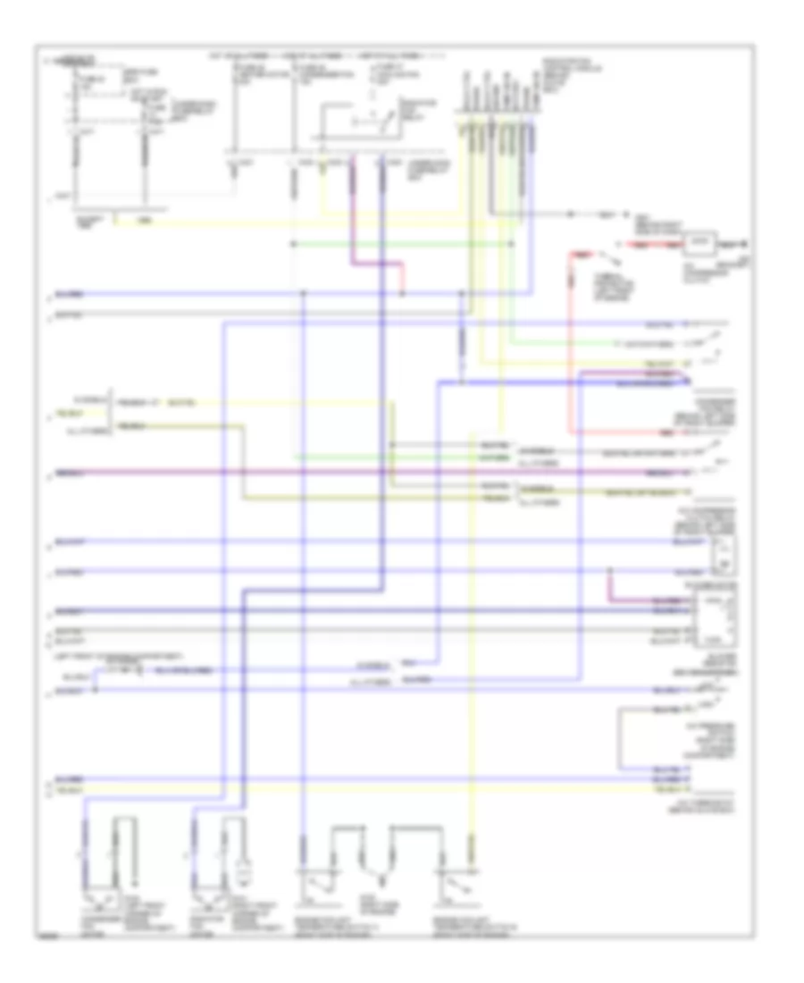
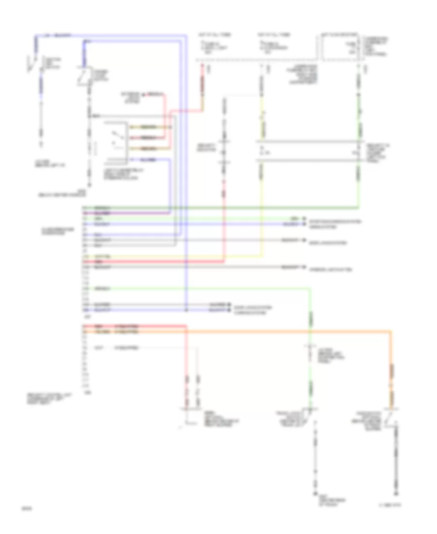
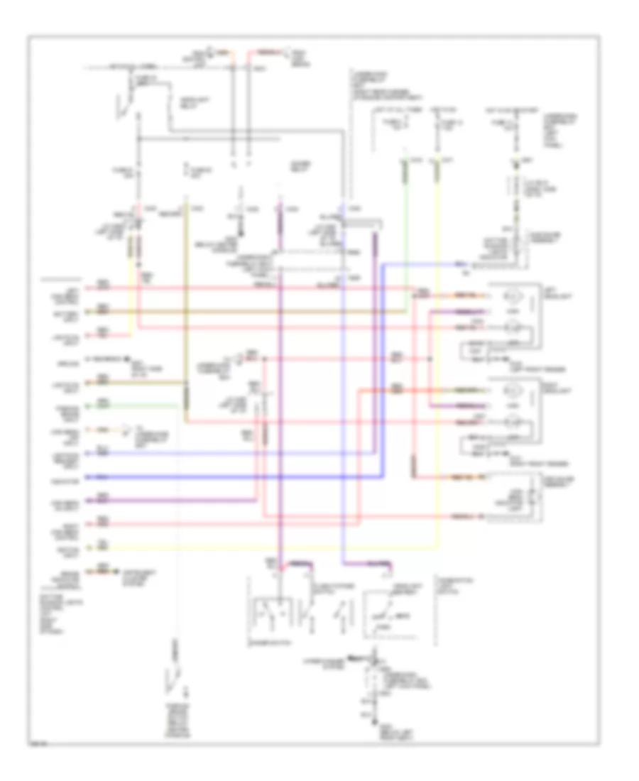
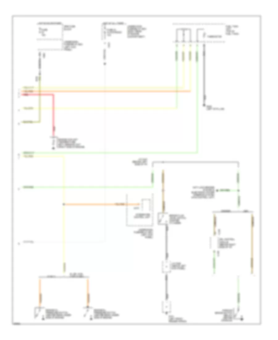
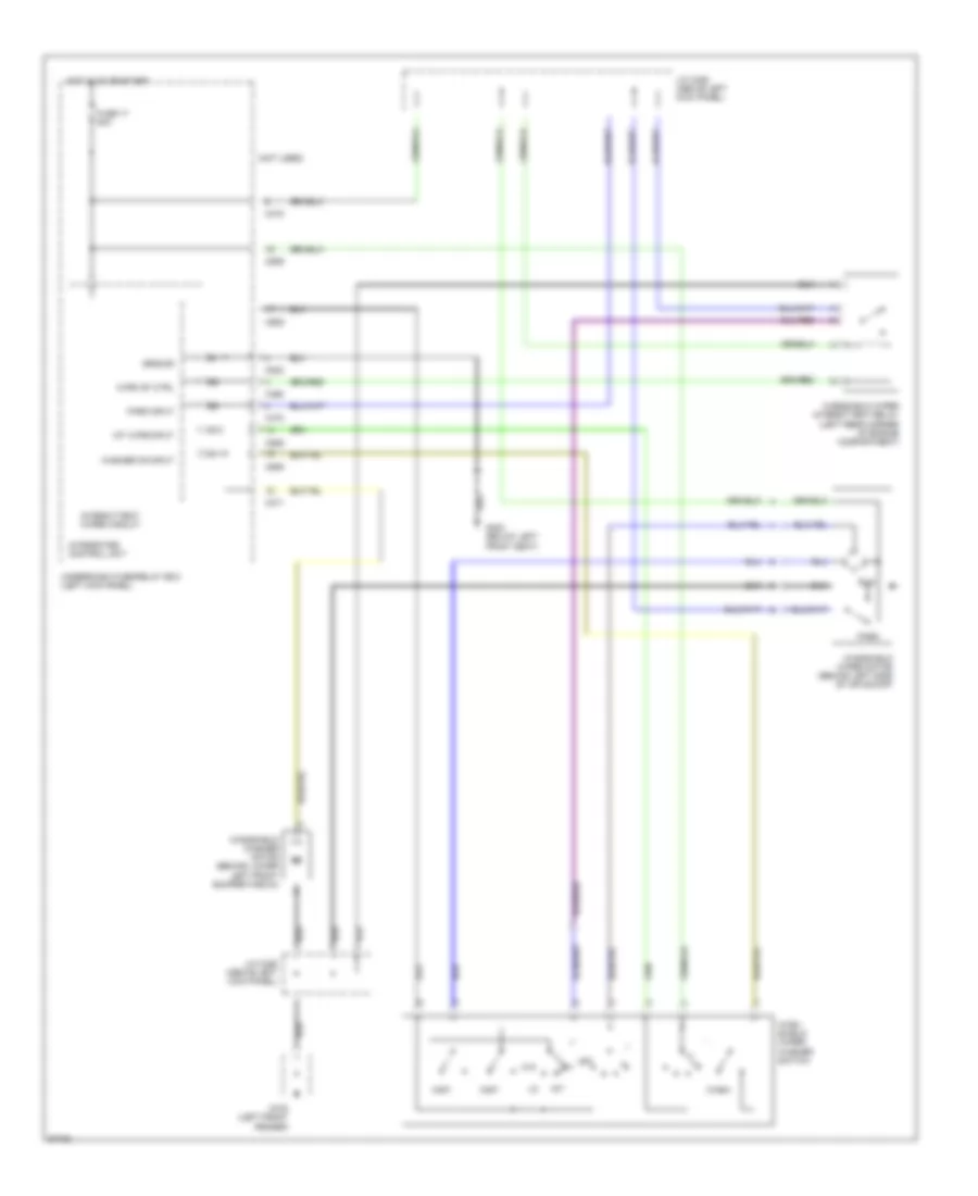
AIR CONDITIONING
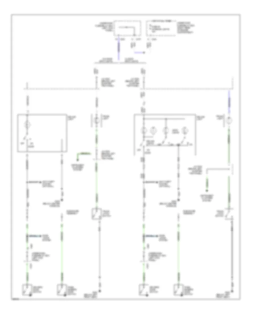
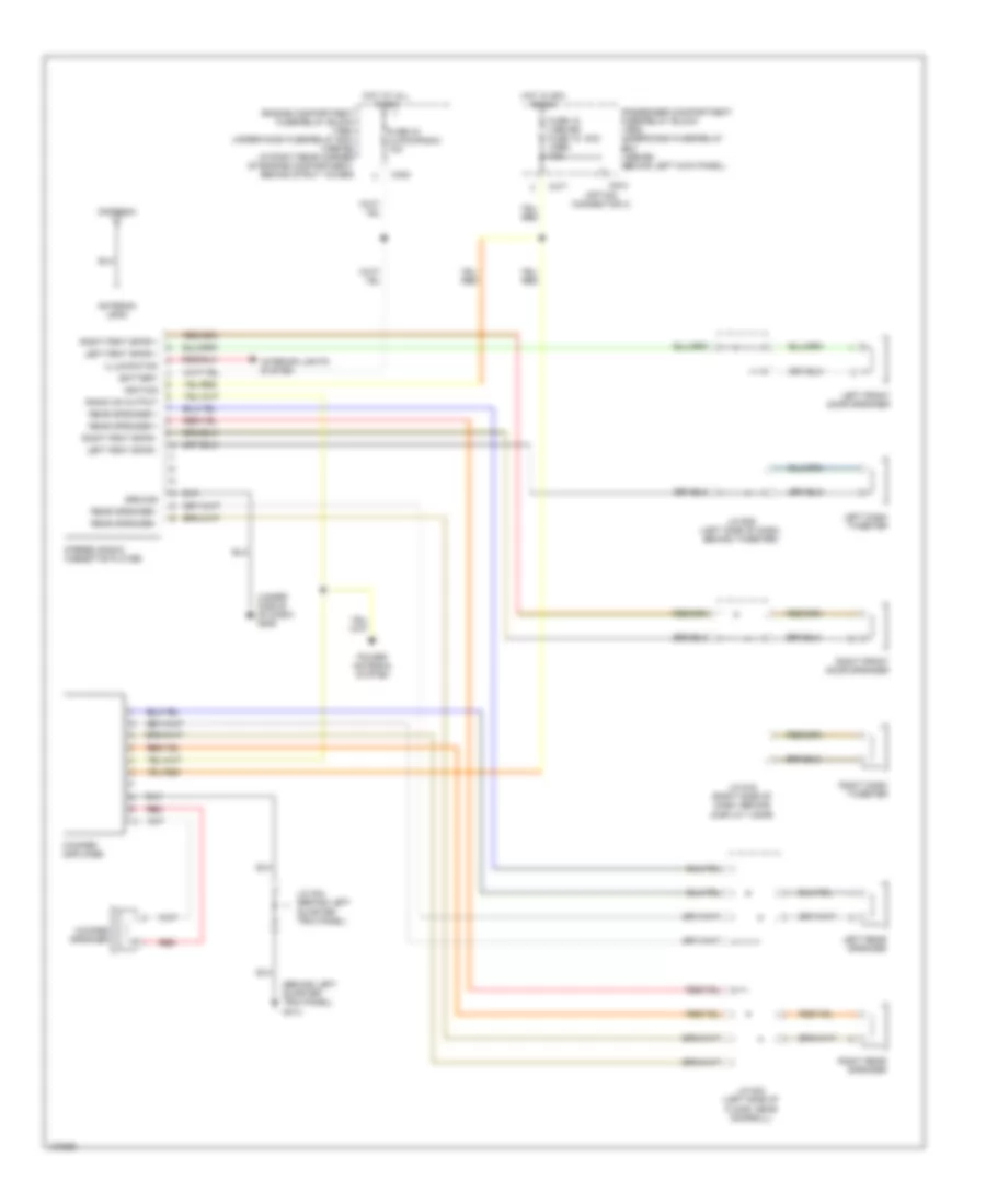
A/C Wiring Diagram (1 of 2) for Honda Prelude 4WS 1994
 https://portal-diagnostov.com/license.html
Automotive Electricians Portal FZCO
Automotive Electricians Portal FZCO
https://portal-diagnostov.com/license.html
https://portal-diagnostov.com/license.html
Automotive Electricians Portal FZCO
Automotive Electricians Portal FZCO
List of elements for A/C Wiring Diagram (1 of 2) for Honda Prelude 4WS 1994:
- (behind front console) g206
- (behind glove box)
- (behind right side of dash)
- A/c switch
- A12
- A15
- A17
- A27
- Bi-lev switch
- Blower motor relay
- C 1995 vftc
- C467
- C468
- C469
- C471
- C472
- Defrost switch
- Dimming circuit
- Engine or powertrain control module (right front floor, under carpet)
- Fresh
- Fresh/ recirc switch
- Fuse 11 10a
- Fuse 9 15a
- G201
- G206 (behind front console)
- Heat switch
- Heat/def switch
- Heater control panel
- Heater fan switch
- Hot in on
- Hot in on or start
- Interior lights system
- J/b
- J/c (1996)
- Mode control motor (below i/p, right of steering column)
- Off
- Recirc
- Recirculation control motor
- Red
- Transmission controls system
- Under-dash fuse/relay box
- Vent switch
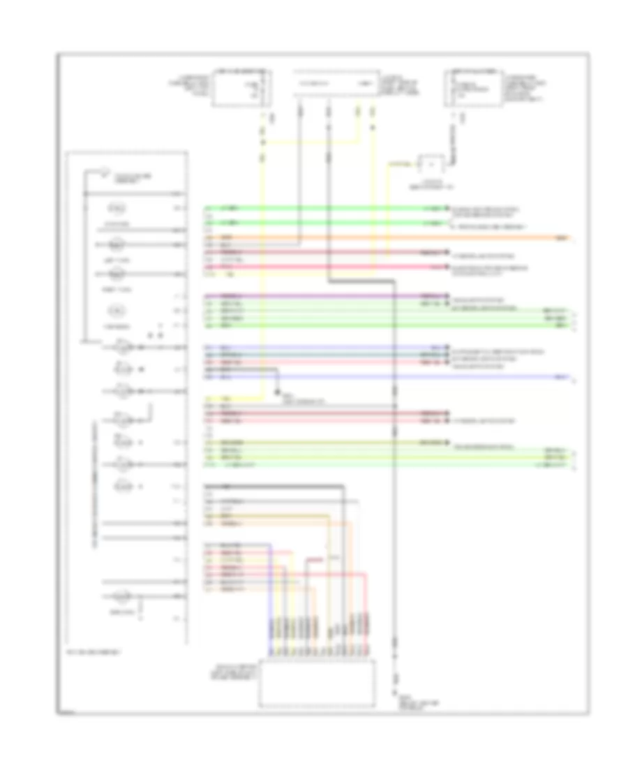
A/C Wiring Diagram (2 of 2) for Honda Prelude 4WS 1994
List of elements for A/C Wiring Diagram (2 of 2) for Honda Prelude 4WS 1994:
- (behind glove box)
- (left front of engine compartment)
- (on bracket)
- A/c compressor clutch
- A/c compressor clutch relay (behind left side of front bumper)
- A/c diode
- A/c pressure switch (right side of engine compartment)
- A/c thermostat (behind glove box)
- All others
- Battery
- Blower motor
- Blower resistor
- C 1995 vftc
- C421
- C423
- C424
- C471
- Condenser fan motor
- Condenser fan relay (behind left side of front bumper)
- Cooling fan 20a
- Engine coolant temperature switch a (right side of engine)
- Engine coolant temperature switch b (right side of engine)
- Except
- Fuse 23 15a
- Fuse 35 heater motor 40a
- Fuse 45 condenser fan 15a
- Fuse 47
- Fuse 7.5a
- G100 (left front corner of engine compartment)
- G101 (right front corner of engine compartment)
- G120 (right side of engine)
- G201 (behind right side of dash)
- Ground
- High
- Hot at all times
- Hot in on or start
- Hot in run or start
- Low
- Power
- Radiator fan control module (behind glove box)
- Radiator fan motor
- Radiator fan relay
- Red
- Relay ctrl
- S models
- Srs fuse box
- Temp sw in
- Thermal protector (left front of engine)
- Under-dash fuse/relay box
- Under-hood fuse/relay box
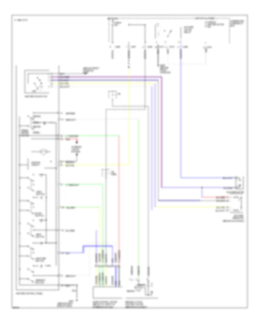
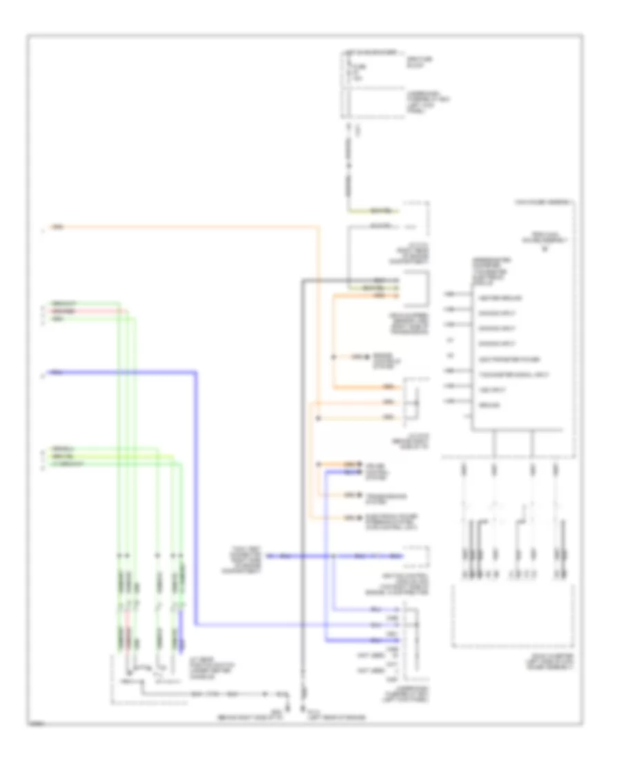
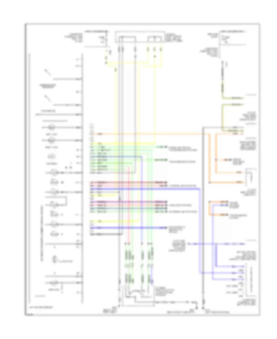
Heater Wiring Diagram for Honda Prelude 4WS 1994
List of elements for Heater Wiring Diagram for Honda Prelude 4WS 1994:
- (behind front console) g206
- (behind glove box)
- (behind right side of dash)
- Bi-lev switch
- Blower motor
- Blower motor relay
- Blower resistor
- C 1995 vftc
- C421
- C467
- C468
- C469
- C471
- C472
- Defrost switch
- Dimming circuit
- Fresh
- Fresh/ recirc switch
- Fuse 36 heater motor 40a
- Fuse 9 15a
- G201
- G206 (behind front console)
- Heat switch
- Heat/def switch
- Heater control panel
- Heater fan switch
- Hot at all times
- Hot in on
- Interior lights system
- J/b
- J/b (1996)
- Mode control motor (below i/p, right of steering column)
- Off
- Recirc
- Recirculation control motor
- Red
- Under-dash fuse/relay box
- Vent switch
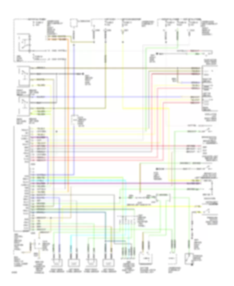
ANTI-LOCK BRAKES
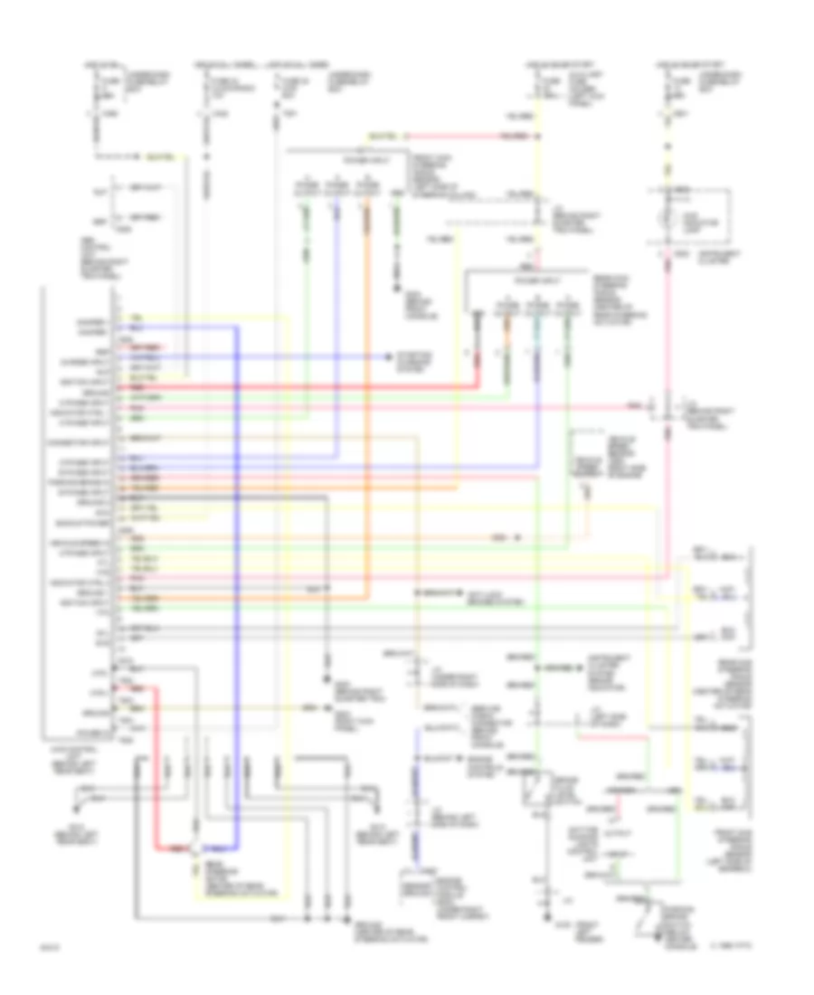
Anti-lock Brake Wiring Diagrams, with Four Wheel Steering for Honda Prelude 4WS 1994
List of elements for Anti-lock Brake Wiring Diagrams, with Four Wheel Steering for Honda Prelude 4WS 1994:
- (behind left side of i/p)
- (behind right side of i/p)
- (right rear of engine compart.)
- (right side of i/p)
- +b1
- +b2
- +b3
- 4
- 4ws cntrl unit (behind left rear seat)
- Abs control unit (behind right quarter trim panel)
- Abs ind
- Abs inspection connector (under right front seat)
- Abs pump relay
- Alternator
- Brake fluid level switch (left rear eng comp)
- Brake switch (top of brake pedal support)
- Brk ind
- C419
- C419 (behind right side of i/p)
- C422
- C423
- C424
- C447
- C505
- C506
- C507 (behind right quarter trim panel)
- Can
- Chg
- Com-
- Daytime running lights control unit
- E21
- E22
- E23
- Ecm (right front of floor, under carpet)
- Fl-in
- Fl-out
- Flw+
- Flw-
- Fr-in
- Fr-out
- Front fail-safe relay
- Frw+
- Frw-
- Fsr
- Fuse 13 10a
- Fuse 31 50a
- Fuse 40 15a
- Fuse 41 15a
- Fuse 48 7.5a
- Fuse 49 20a
- Fuse 9 15a
- G100 (left front fender)
- G201
- G201 (behind right side of i/p)
- Headlamps
- Hot at all times
- Hot in on
- Hot in on or start
- Ig2
- Indicators
- Instrument cluster
- Left fr abs sol
- Left front wheel sensor
- Left rear wheel sensor
- Mck
- Modulator unit (right rear eng comp)
- Park
- Parking brake switch
- Pmr
- Pressure switch (right rear eng comp)
- Psw
- Pump motor (right rear eng comp)
- R-in
- R-out
- Rear abs sol
- Rear fail-safe relay
- Red
- Right fr abs sol
- Right front wheel sensor
- Right rear wheel sensor
- Rlp
- Rlw+
- Rlw-
- Rrp
- Rrw+
- Rrw-
- Scs
- Service check connector (behind front console)
- Stop
- Under-dash fuse/relay box
- Under-hood abs fuse/relay box
- Usa
- Warn 1
- Warn 2
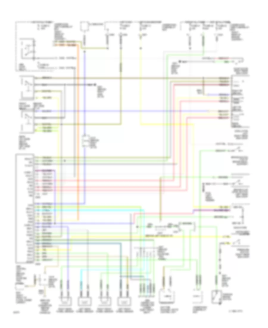
Anti-lock Brake Wiring Diagrams, without Four Wheel Steering for Honda Prelude 4WS 1994
List of elements for Anti-lock Brake Wiring Diagrams, without Four Wheel Steering for Honda Prelude 4WS 1994:
- (behind left side of i/p)
- (behind right side of i/p)
- (right rear of engine compart.)
- +b1
- +b2
- +b3
- 1995 vftc c
- 5
- Abs control unit (behind right quarter trim panel)
- Abs ind
- Abs inspection connector (under right front seat)
- Abs pump relay
- Alternator
- Brake fluid level switch (left rear eng comp)
- Brake switch (top of brake pedal support)
- Brk ind
- C419
- C419 (behind right side of i/p)
- C422
- C423
- C424
- C447
- C505
- C506
- C507 (behind right quarter trim panel)
- Can
- Chg
- Com-
- Daytime running lights control unit
- E21
- E22
- E23
- Ecm (right front of floor, under carpet)
- Fl-in
- Fl-out
- Flw+
- Flw-
- Fr-in
- Fr-out
- Front fail-safe relay
- Frw+
- Frw-
- Fsr
- Fuse 13 10a
- Fuse 31 50a
- Fuse 40 15a
- Fuse 41 15a
- Fuse 48 7.5a
- Fuse 49 20a
- Fuse 9 15a
- G100 (left front fender)
- G201
- G201 (behind right side of i/p)
- Headlamps
- Hot at all times
- Hot in on
- Hot in on or start
- Ig2
- Indicators
- Instrument cluster
- Left fr abs sol
- Left front wheel sensor
- Left rear wheel sensor
- Mck
- Modulator unit (right rear eng comp)
- Park
- Parking brake switch
- Pmr
- Pressure switch (right rear eng comp)
- Psw
- Pump motor (right rear eng comp)
- R-in
- R-out
- Rear abs sol
- Rear fail-safe relay (behind left side of i/p)
- Red
- Right fr abs sol
- Right front wheel sensor
- Right rear wheel sensor
- Rlw+
- Rlw-
- Rrw+
- Rrw-
- Scs
- Service check connector (behind front console)
- Stop
- Under-dash fuse/relay box
- Under-hood abs fuse/relay box
- Usa
- Warn 1
- Warn 2
ANTI-THEFT
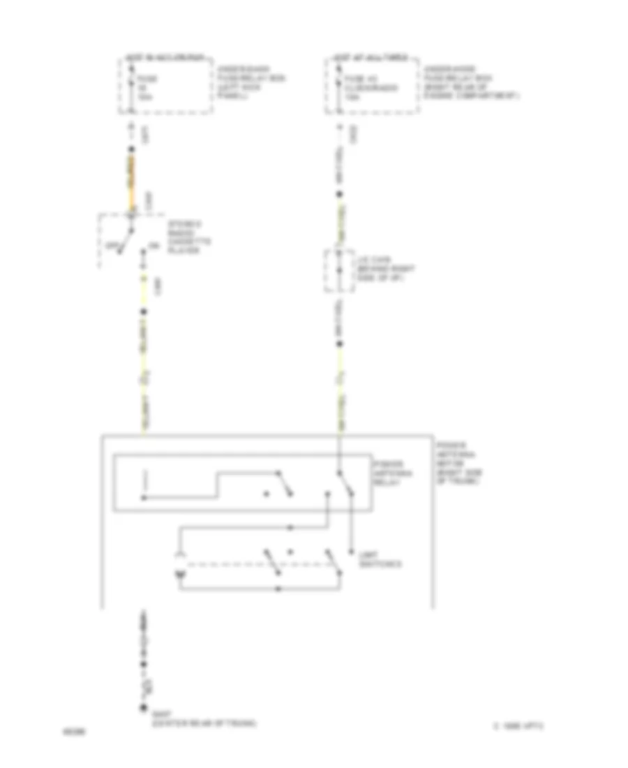
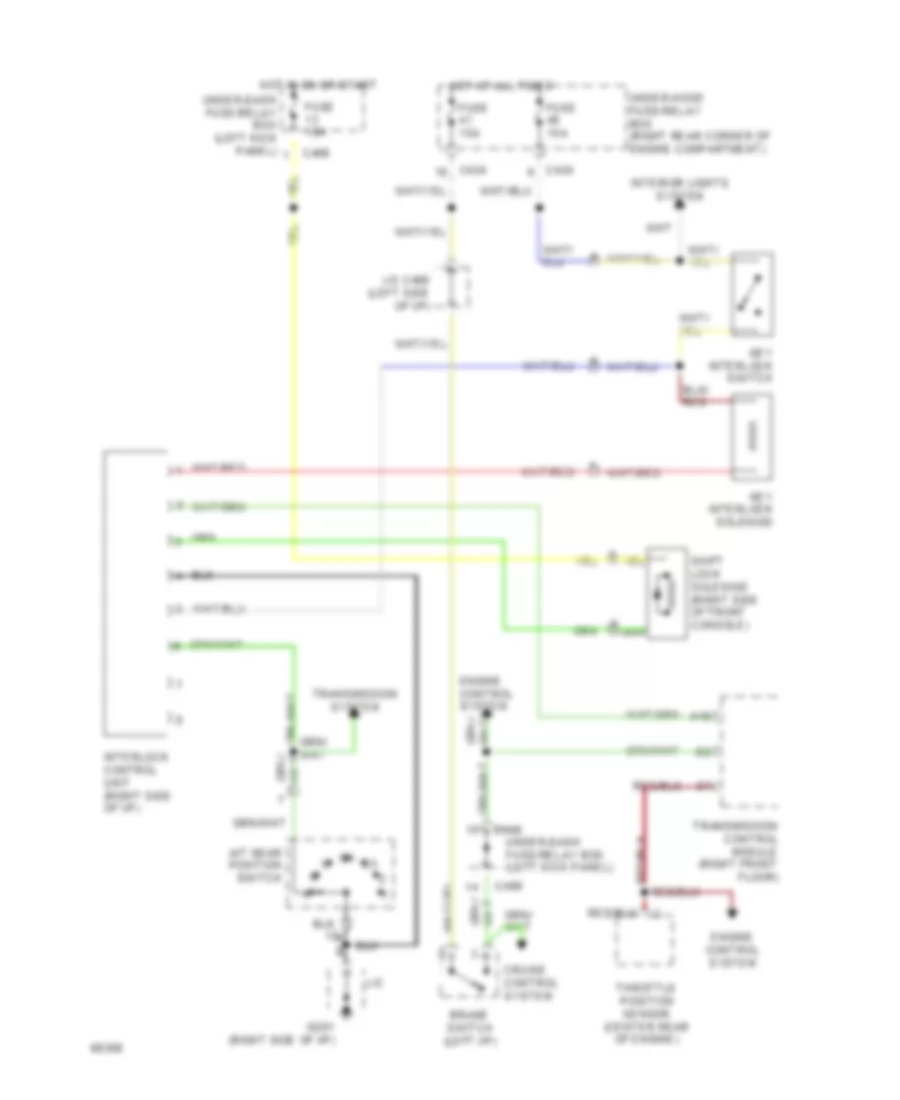
Anti-theft Wiring Diagram for Honda Prelude 4WS 1994
List of elements for Anti-theft Wiring Diagram for Honda Prelude 4WS 1994:
- (if equipped)
- 10a
- 1995 vftc c
- 20a
- 30a
- C422
- C424
- C472
- C57
- C58
- Disarm/ valet switch
- Door locks system
- Exterior lights system
- Fuse
- Fuse 42 small light
- Fuse 43 clock/radio
- G302 (below center console)
- G407 (center rear of trunk)
- Glass breakage microphone
- Hood switch (optional) (behind center of front bumper)
- Horns system
- Hot at all times
- Hot in on or start
- Ignition key switch
- Interior lights sytem
- J/c c460 (behind left i/p)
- J/c c534 (behind left quarter trim panel)
- Light flasher relay (right side of steering column)
- Nca
- Red
- Security control unit (underside of left front seat)
- Security in- line fuse holder (left kick panel)
- Security indicator
- Siren (optional) (behind center of front bumper)
- Starting/charging system
- Trunk latch switch (center of trunk lid)
- Under-dash fuse/relay box (left kick panel)
- Under-hood fuse/relay box (right side of engine compartment)
- Warning system
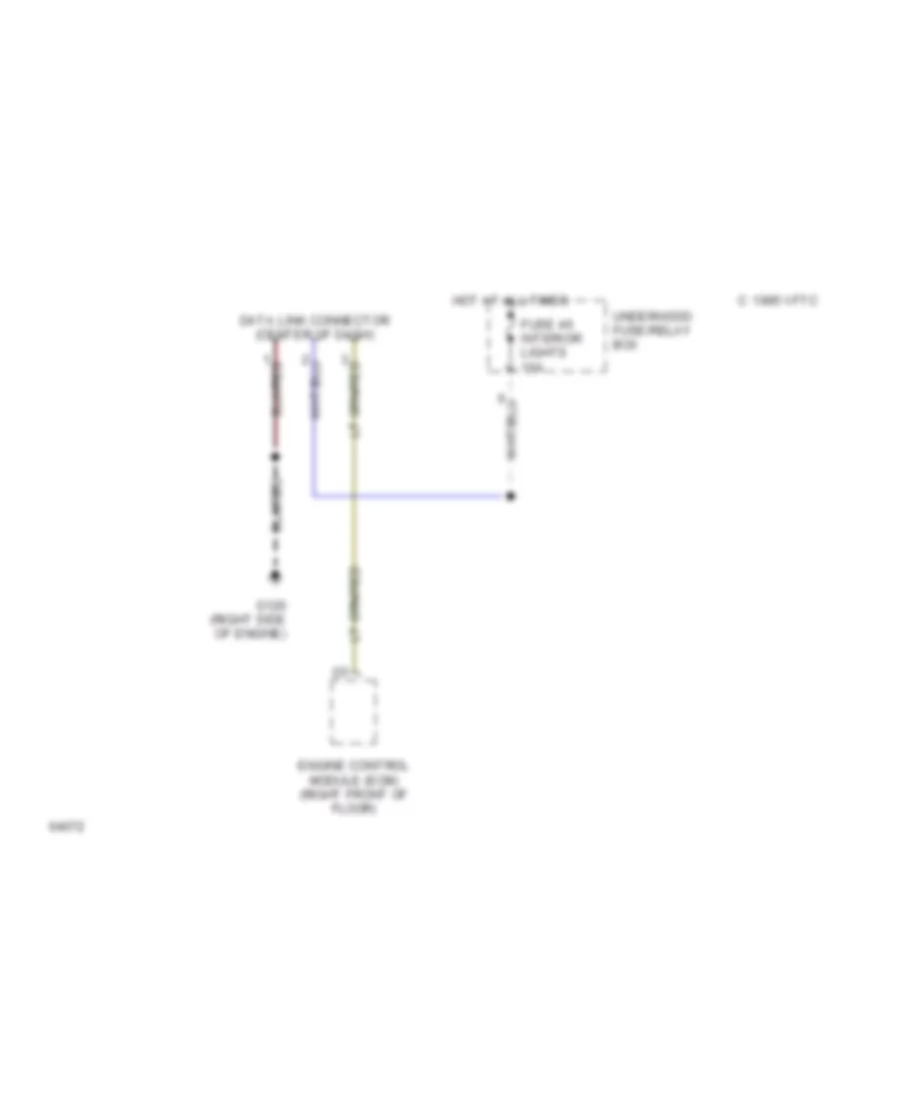
COMPUTER DATA LINES
Data Link Connector Wiring Diagram for Honda Prelude 4WS 1994
List of elements for Data Link Connector Wiring Diagram for Honda Prelude 4WS 1994:
- C 1995 vftc
- Data link connector (center of dash)
- Engine control module (ecm) (right front of floor)
- Fuse 46 interior lights 15a
- G120 (right side of engine)
- Hot at all times
- Underhood fuse/relay box
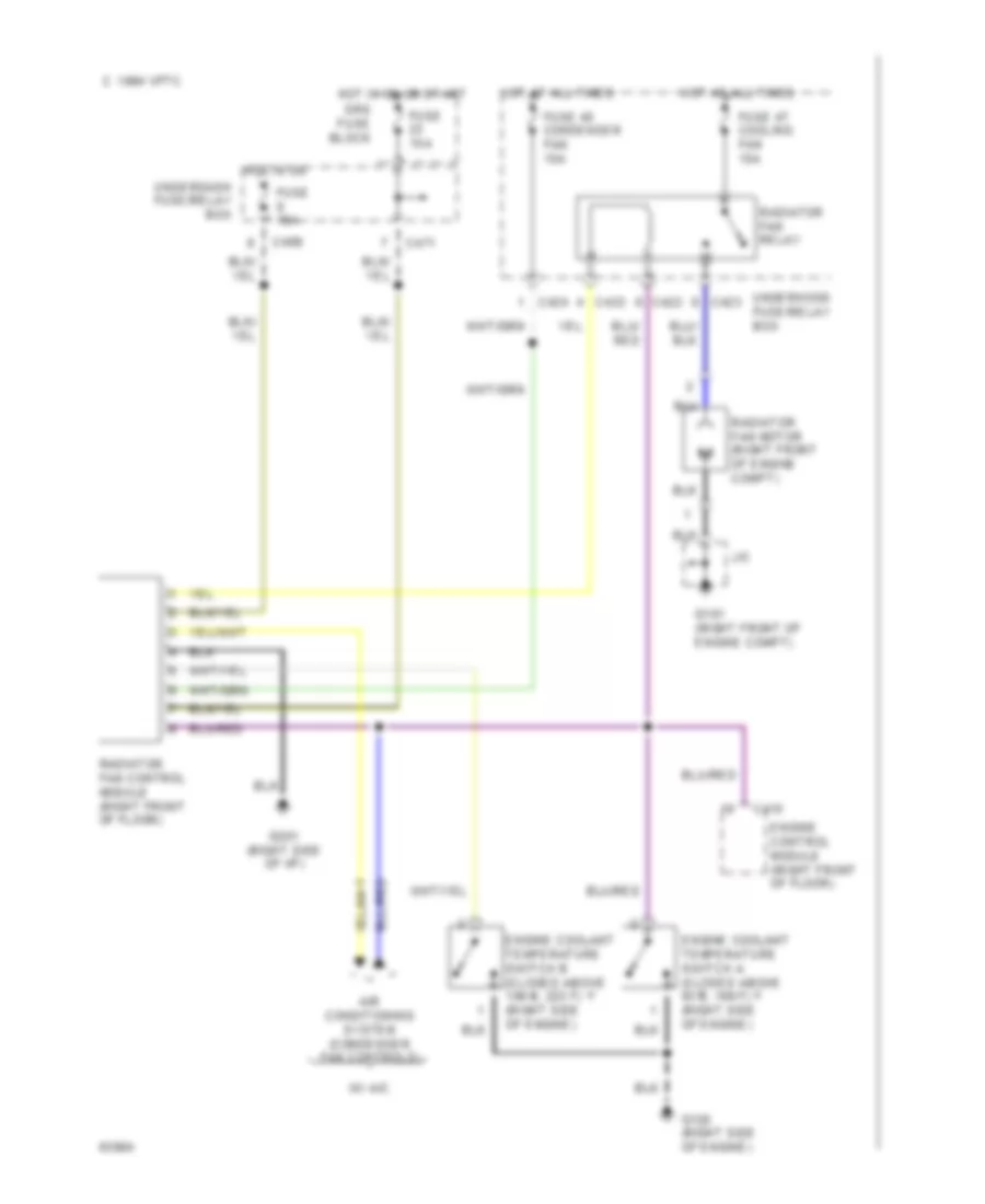
COOLING FAN
Cooling Fan Wiring Diagram for Honda Prelude 4WS 1994
List of elements for Cooling Fan Wiring Diagram for Honda Prelude 4WS 1994:
- 1994 vftc c
- Air conditioning system (condenser fan controls)
- C415
- C422
- C423
- C424
- C469
- C471
- Engine control module (right front of floor)
- Engine coolant temperature switch a (closed above 93 c, 199 f) (right side of engine)
- Engine coolant temperature switch b (closed above 106 c, 223 f) (right side of engine)
- Fuse 15a
- Fuse 45 condenser fan 15a
- Fuse 47 cooling fan 15a
- G101 (right front of engine compt)
- G120 (right side of engine)
- G201 (right side of i/p)
- Hot at all times
- Hot in on
- Hot in on or start
- J/c
- Radiator fan control module (right front of floor)
- Radiator fan motor (right front of engine compt)
- Radiator fan relay
- Srs fuse block
- Underdash fuse/relay box
- Underhood fuse/relay box
- W/ a/c
CRUISE CONTROL
Cruise Control Wiring Diagram for Honda Prelude 4WS 1994
List of elements for Cruise Control Wiring Diagram for Honda Prelude 4WS 1994:
- (not used)
- 1995 vftc c
- A/t
- A/t gear position switch (left side of front console)
- Actuator input
- Brake input
- Brake switch
- C424
- C471
- C523
- C601
- Clutch switch
- Cruise control actuator (left front corner of engine compartment)
- Cruise control indicator
- Cruise control main switch
- Cruise control set/ resume switch
- Cruise control unit (left side of i/p)
- Dimmer
- Disengage input
- E17
- E9 red
- Engine rpm input
- Fuse 10a
- Fuse 15a
- Fuse 7.5a
- G100 (left front fender)
- G201 (left side of i/p)
- G201 (right side of i/p)
- G300 (below left front seat)
- G302 (below center console)
- Ground
- Horn relay left kick panel)
- Horn switches
- Hot at all times
- Hot in on or start
- Indicator light control
- Instrument cluster system
- Interior lights system
- J/c
- J/c c460 (left of i/p)
- J/c c619 (right of i/p)
- J/c c619 (right side of i/p)
- M/t
- Nca
- Off
- Pnk
- Power input
- Red
- Resume/ accel sig input
- Resume/ accel switch
- Safety solenoid
- Set/decel sig input
- Set/decel switch
- Srs cable reel (top of steering column)
- Steering wheel
- Sub gauge assembly
- Under-dash fuse/relay box (left kick panel)
- Under-hood fuse/relay box (right rear corner of engine compartment)
- Vacuum solenoid
- Vehicle speed input
- Vent solenoid
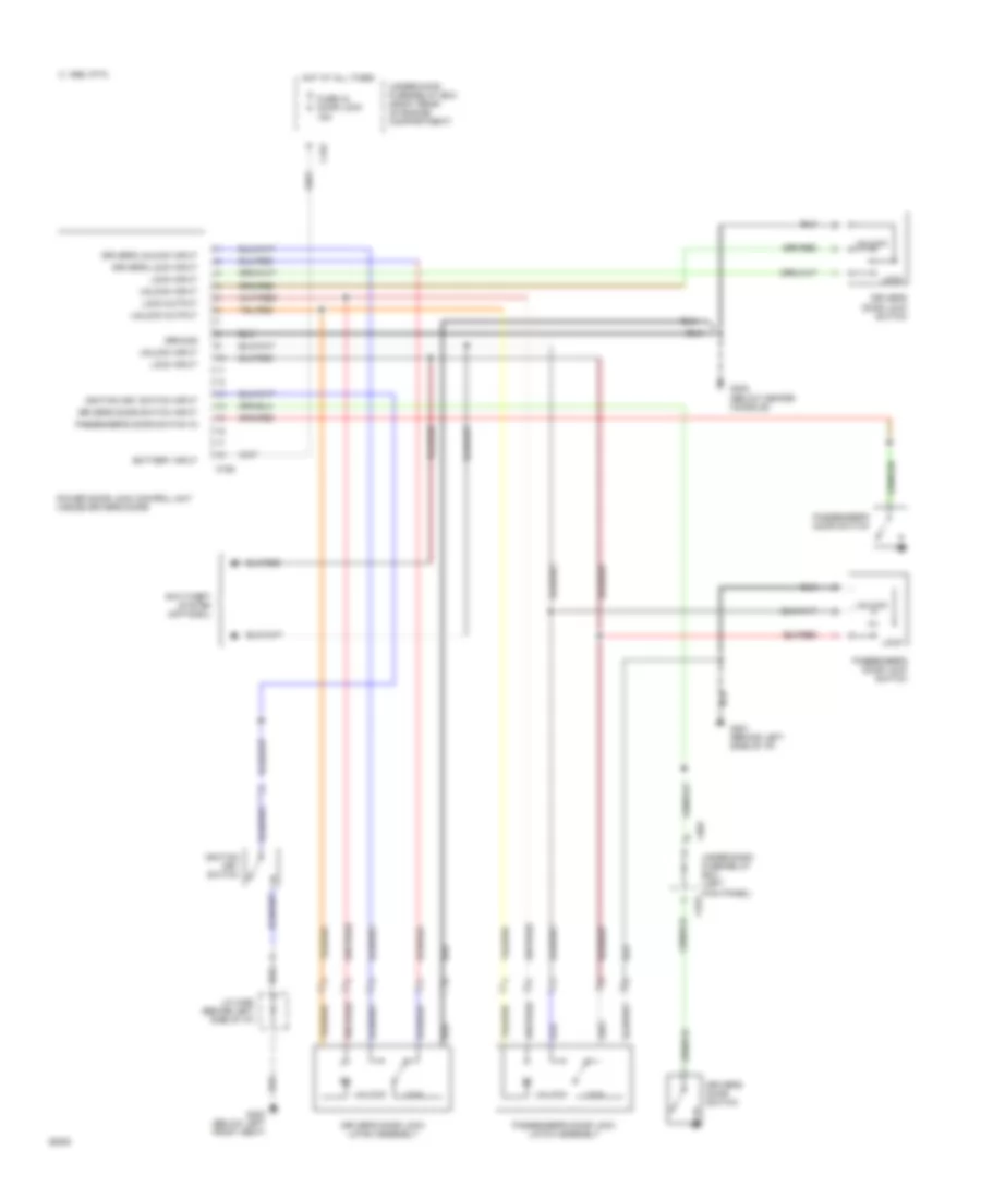
DEFOGGERS
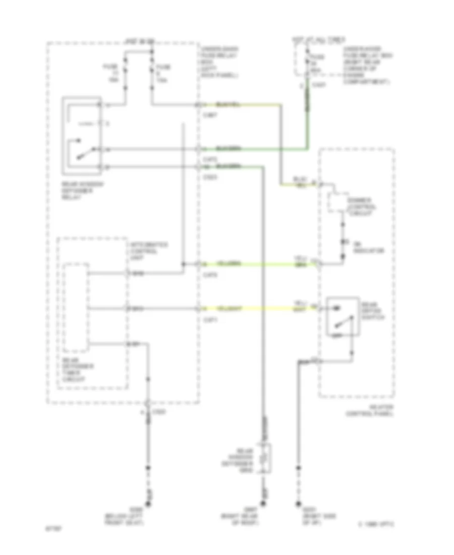
Defogger Wiring Diagram for Honda Prelude 4WS 1994
List of elements for Defogger Wiring Diagram for Honda Prelude 4WS 1994:
- 1995 vftc c
- B12
- B13
- C421
- C467
- C470
- C471
- C472
- C523
- Dimmer control circuit
- Fuse 10a
- Fuse 15a
- Fuse 40a
- G201 (right side of i/p)
- Heater control panel
- Hot at all times
- Hot in on
- Integrated control unit
- Off
- On indicator
- Rear defog switch
- Rear defogger timer circuit
- Rear window defogger grid
- Rear window defogger relay
- Under-dash fuse/relay box (left kick panel)
- Under-hood fuse/relay box (right rear corner of engine compartment)
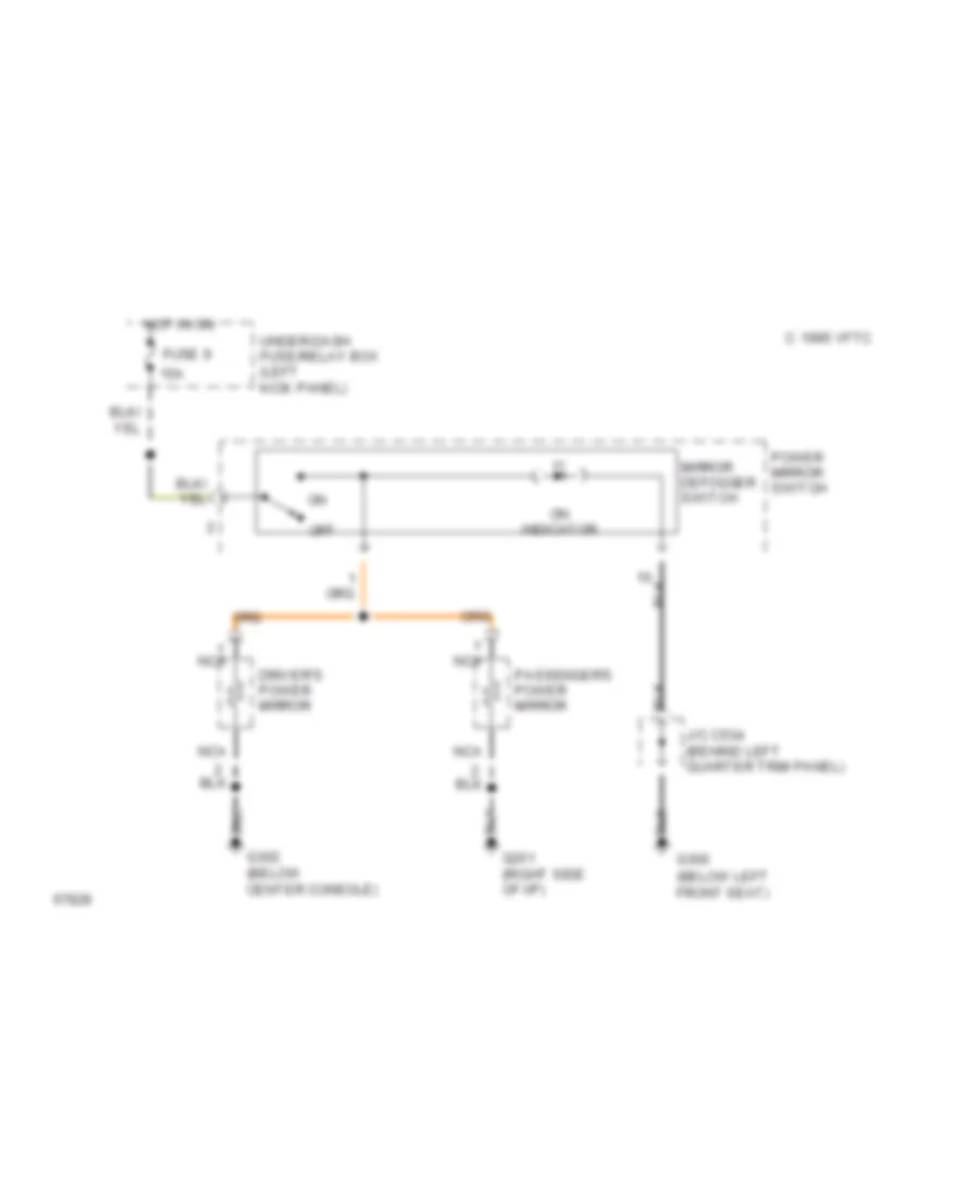
Heated Mirrors Wiring Diagram for Honda Prelude 4WS 1994
List of elements for Heated Mirrors Wiring Diagram for Honda Prelude 4WS 1994:
- (below left front seat)
- 15a
- 1995 vftc c
- Driver's power mirror
- Fuse 9
- G201 (right side of i/p)
- G300
- G302 (below center console)
- Hot in on
- J/c c534 (behind left quarter trim panel)
- Mirror defogger switch
- Nca
- Off
- On indicator
- Passenger's power mirror
- Power mirror switch
- Under-dash fuse/relay box (left kick panel)
ELECTRONIC POWER STEERING
Electronic Power Steering Wiring Diagram for Honda Prelude 4WS 1994
List of elements for Electronic Power Steering Wiring Diagram for Honda Prelude 4WS 1994:
- (front left fender)
- 4ws control unit (behind left rear seat)
- 4ws indicator lamp
- A phase input
- A phase output
- Abs control unit (behind right quarter trim panel)
- Anti-lock brakes system
- Auxiliary fuse holder (left kick panel)
- B phase input
- B phase output
- Backup power
- Brake fluid level switch
- C 1995 vftc
- C417
- C422
- C468
- C505
- C508
- C509
- C510
- C623
- Canada
- Charge input
- Connector input
- Damper +
- Damper -
- Daytime running lights control unit
- Engine control module (ecm) (under right front carpet)
- Engine controls system
- Front main steering angle sensor (left side of steering column)
- Front sub steering angle sensor (left side of gearbox)
- Ftl
- Ftm
- Ftr
- Fuse 10a
- Fuse 15a
- Fuse 38 4ws 60a
- Fuse 43 clock/radio 10a
- G100
- G203 (right kick panel)
- G302 (behind front console)
- G312 (behind left rear seat)
- G403 (behind right quarter trim)
- Grd
- Ground
- Ground (center of rear steering actuator)
- Ground 1
- Ground 2
- Hot at all times
- Hot in on
- Hot in on or start
- Ignition input
- Indicator ctrl 1
- Indicator ctrl 2
- Input
- Instrument cluster
- Instrument cluster system (brake indicator)
- J/c
- J/c (behind left side of dash)
- J/c (behind right quarter trim panel)
- J/c (left side of dash)
- J/c (under right side of dash)
- Mtr +
- Mtr -
- Output
- Parking brake in
- Parking brake switch (below center console)
- Pnk
- Power in
- Power input
- Rear main steering angle sensor (center of rear steering actuator)
- Rear steering motor (center of rear steering actuator)
- Rear sub steering angle sensor (center of rear steering actuator)
- Red
- Rlp
- Rrp
- Rtl
- Rtm
- Rtr
- Sensor ground
- Service check connector (behind front console)
- Starting/ charging system
- T502
- T503
- T504
- T505
- Under-dash fuse/relay box
- Usa
- Vehicle speed in
- Vehicle speed output
- Vehicle speed sensor (vss) (right side of engine
- Z phase input
- Z phase output
ENGINE PERFORMANCE
2.2L
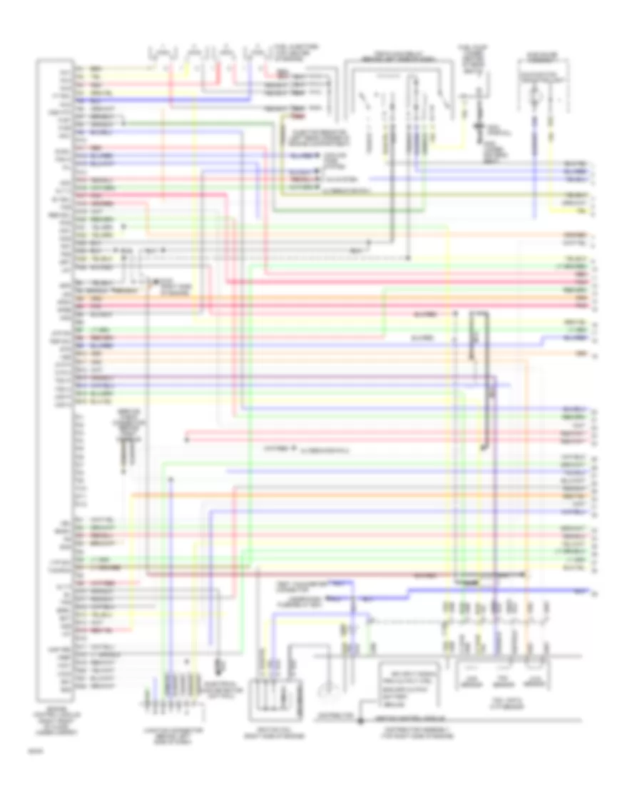
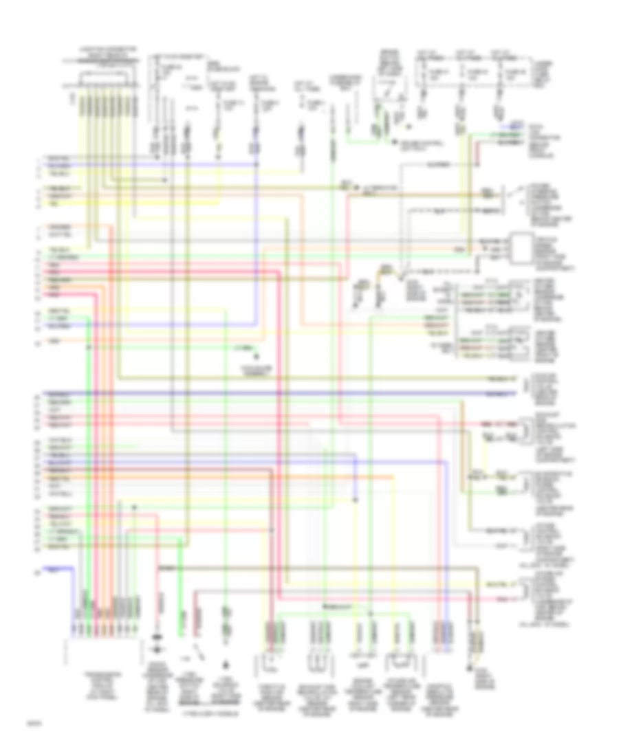
2.2L, Engine Performance Wiring Diagrams (1 of 2) for Honda Prelude 4WS 1994
List of elements for 2.2L, Engine Performance Wiring Diagrams (1 of 2) for Honda Prelude 4WS 1994:
- A/c system
- A10
- A11
- A12
- A13
- A14
- A15
- A16
- A17
- A18
- A19
- A20
- A21
- A22
- A23
- A24
- A25
- A26
- Acc
- Acs
- Afsa
- Afsb
- Alt c
- Alt f
- Alternator pin 1
- Alternator pin 2
- Atp pn
- B10
- B11
- B12
- B13
- B14
- B15
- B16
- Battery
- Bksw
- C10
- C11
- C12
- C125
- C126
- C447
- C534 (partial)
- Ckp m
- Ckp p
- Ckp sensor
- Cooling fans system
- Cyp m
- Cyp p
- Cyp sensor
- D10
- D11
- D12
- D13
- D14
- D15
- D16
- D17
- D18
- D19
- D20
- D21
- D22
- Distributor
- Distributor assembly (top right side of engine)
- E sol
- E10
- E23
- Ect
- Egrl
- Electrical load detector unit pin 2
- Eng spd output
- Engine control module (right front of floor, under carpet)
- Fan h
- Fas
- Flr1
- Flr2
- Fuel injectors (top center of engine)
- Fuel pump (under center of rear seats)
- G120 (right side of engine)
- G300 (under driver's seat)
- Ground
- Iacv
- Iat
- Icm1
- Icm2
- Ign input signal
- Ignition coil (right side of engine)
- Ignition control module
- Igp1
- Igp2
- Inj1
- Inj2
- Inj3
- Inj4
- Injector resistor (left rear corner of engine compartment)
- Junction connector (behind left side of dash)
- Lg1
- Lg2
- Malfunction indicator light
- Map (pb)
- Mil
- Nca
- O2s
- O2s htc
- Pcs
- Pg1
- Pg2
- Pgm-fi main relay (behind left side of dash)
- Pnk
- Prim output ctrl
- Primary
- Psp sw
- Red
- Res sol
- Scs
- Secondary
- Sg1
- Sg2
- Sts
- Sub gauge assembly
- Sv sol
- Tdc m
- Tdc p
- Tdc sensor
- Tdc, ckp & cyp sensor
- Test tachometer connector
- Tps
- Txd/rxd
- Under-dash fuse/relay box
- Vbu
- Vcc1
- Vcc2
- Vref
- Vss
- Vt sol
- Vtp sw
2.2L, Engine Performance Wiring Diagrams (2 of 2) for Honda Prelude 4WS 1994
List of elements for 2.2L, Engine Performance Wiring Diagrams (2 of 2) for Honda Prelude 4WS 1994:
- all except "s" model
- "s" model only
- "s" model)
- (all exc. "s" model)
- (behind front console)
- (center rear of engine)
- (left side of engine compartment)
- (right rear of engine compartment)
- (right side of engine compartment)
- (underside of car, behind center of engine)
- (vtec & sr-v models)
- A19
- Alternator pin 3
- Brake switch (behind left side of dash)
- C114
- C131
- C479
- C908
- Cruise control unit pin 4
- D11
- D13
- D16
- D18
- Engine coolant temperature sensor (right side of engine)
- Evaporative emission purge control solenoid valve
- Exhaust gas recirculation control solenoid valve
- Exhaust gas recirculation valve lift sensor (center rear of engine)
- Fuse 13 10a
- Fuse 2 7.5a
- Fuse 23 15a
- Fuse 4 10a
- Fuse 41 15a
- Fuse 43 10a
- Fuse 46 15a
- G120 (right side of engine)
- Heated oxygen sensor (center front of engine)
- Heated oxygen sensor (underside of car, behind center of engine)
- Hot at all times
- Hot in on or start
- Hot w/ engine cranking
- Idle air control valve (center rear of engine)
- Intake air bypass control solenoid valve
- Intake air temperature sensor (left rear corner of engine)
- Intake control solenoid valve
- Junction connector
- Knock sensor (underside of car, center rear of engine) (all exc.
- Main gauge assembly
- Manifold absolute pressure sensor (center rear of engine)
- Nca
- Pnk
- Power steering pressure switch (underside of car, behind center of engine)
- Red
- Srs fuse block
- Throttle position sensor (center rear of engine)
- Transmission control module (at right kick panel)
- Under- hood fuse/ relay box
- Under-dash fuse/relay box
- Vehicle speed sensor
- Vtec pressure switch (right side of engine)
- Vtec solenoid valve (right side of engine)
2.3L
2.3L, Engine Performance Wiring Diagrams (1 of 2) for Honda Prelude 4WS 1994
List of elements for 2.3L, Engine Performance Wiring Diagrams (1 of 2) for Honda Prelude 4WS 1994:
- A/c system
- A10
- A11
- A12
- A13
- A14
- A15
- A16
- A17
- A18
- A19
- A20
- A21
- A22
- A23
- A24
- A25
- A26
- Acc
- Acs
- Afsa
- Afsb
- Alt c
- Alt f
- Alternator pin 1
- Alternator pin 2
- Atp pn
- B10
- B11
- B12
- B13
- B14
- B15
- B16
- Battery
- Bksw
- C10
- C11
- C12
- C125
- C126
- C447
- C534 (partial)
- Ckp m
- Ckp p
- Ckp sensor
- Cooling fans system
- Cyp m
- Cyp p
- Cyp sensor
- D10
- D11
- D12
- D13
- D14
- D15
- D16
- D17
- D18
- D19
- D20
- D21
- D22
- Distributor
- Distributor assembly (top right side of engine)
- E sol
- E10
- E23
- Ect
- Egrl
- Electrical load detector unit pin 2
- Eng spd output
- Engine control module (right front of floor, under carpet)
- Fan h
- Fas
- Flr1
- Flr2
- Fuel injectors (top center of engine)
- Fuel pump (under center of rear seats)
- G120 (right side of engine)
- G300 (under driver's seat)
- Ground
- Iacv
- Iat
- Icm1
- Icm2
- Ign input signal
- Ignition coil (right side of engine)
- Ignition control module
- Igp1
- Igp2
- Inj1
- Inj2
- Inj3
- Inj4
- Injector resistor (left rear corner of engine compartment)
- Junction connector (behind left side of dash)
- Lg1
- Lg2
- Malfunction indicator light
- Map (pb)
- Mil
- Nca
- O2s
- O2s htc
- Pcs
- Pg1
- Pg2
- Pgm-fi main relay (behind left side of dash)
- Pnk
- Prim output ctrl
- Primary
- Psp sw
- Red
- Res sol
- Scs
- Secondary
- Sg1
- Sg2
- Sts
- Sub gauge assembly
- Sv sol
- Tdc m
- Tdc p
- Tdc sensor
- Tdc, ckp & cyp sensor
- Test tachometer connector
- Tps
- Txd/rxd
- Under-dash fuse/relay box
- Vbu
- Vcc1
- Vcc2
- Vref
- Vss
- Vt sol
- Vtp sw
2.3L, Engine Performance Wiring Diagrams (2 of 2) for Honda Prelude 4WS 1994
List of elements for 2.3L, Engine Performance Wiring Diagrams (2 of 2) for Honda Prelude 4WS 1994:
- all except "s" model
- "s" model only
- "s" model)
- (all exc. "s" model)
- (behind front console)
- (center rear of engine)
- (left side of engine compartment)
- (right rear of engine compartment)
- (right side of engine compartment)
- (underside of car, behind center of engine)
- (vtec & sr-v models)
- A19
- Alternator pin 3
- Brake switch (behind left side of dash)
- C114
- C131
- C479
- C908
- Cruise control unit pin 4
- D11
- D13
- D16
- D18
- Engine coolant temperature sensor (right side of engine)
- Evaporative emission purge control solenoid valve
- Exhaust gas recirculation control solenoid valve
- Exhaust gas recirculation valve lift sensor (center rear of engine)
- Fuse 13 10a
- Fuse 2 7.5a
- Fuse 23 15a
- Fuse 4 10a
- Fuse 41 15a
- Fuse 43 10a
- Fuse 46 15a
- G120 (right side of engine)
- Heated oxygen sensor (center front of engine)
- Heated oxygen sensor (underside of car, behind center of engine)
- Hot at all times
- Hot in on or start
- Hot w/ engine cranking
- Idle air control valve (center rear of engine)
- Intake air bypass control solenoid valve
- Intake air temperature sensor (left rear corner of engine)
- Intake control solenoid valve
- Junction connector
- Knock sensor (underside of car, center rear of engine) (all exc.
- Main gauge assembly
- Manifold absolute pressure sensor (center rear of engine)
- Nca
- Pnk
- Power steering pressure switch (underside of car, behind center of engine)
- Red
- Srs fuse block
- Throttle position sensor (center rear of engine)
- Transmission control module (at right kick panel)
- Under- hood fuse/ relay box
- Under-dash fuse/relay box
- Vehicle speed sensor
- Vtec pressure switch (right side of engine)
- Vtec solenoid valve (right side of engine)
EXTERIOR LIGHTS
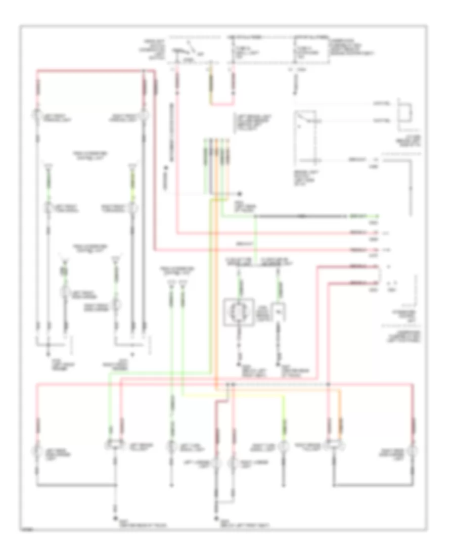
Exterior Light Wiring Diagram (1 of 2) for Honda Prelude 4WS 1994
List of elements for Exterior Light Wiring Diagram (1 of 2) for Honda Prelude 4WS 1994:
- Brake light switch (left side of i/p)
- C424
- C469
- C470
- C523
- C909
- C921
- From integrated control unit
- Fuse 41 stop/horn 15a
- Fuse 42 small light 15a
- G100 (left front fender)
- G101 (right front fender)
- G300 (below left front seat)
- G404 (left rear of trunk)
- G407 (center rear of trunk)
- Head
- Headlight switch (combination light switch)
- High mount brake lights
- Hot at all times
- Instrument cluster system
- Integrated control unit
- J/c c460 (behind left side of i/p)
- Left brake light failure sensor (behind left taillight)
- Left brake/ taillight
- Left front parking light
- Left front side marker
- Left front turn signal
- Left license light
- Left rear side marker light
- Left turn signal light
- Nca
- Off
- Park
- Right brake/ taillight
- Right front parking light
- Right front side marker
- Right front turn signal
- Right license light
- Right rear side marker light
- Right turn signal light
- Under-dash fuse/relay box (left kick panel)
- Under-hood fuse/relay box (right rear of engine compartment)
- W/ bulb type brake light
- W/ spoiler or led brake light
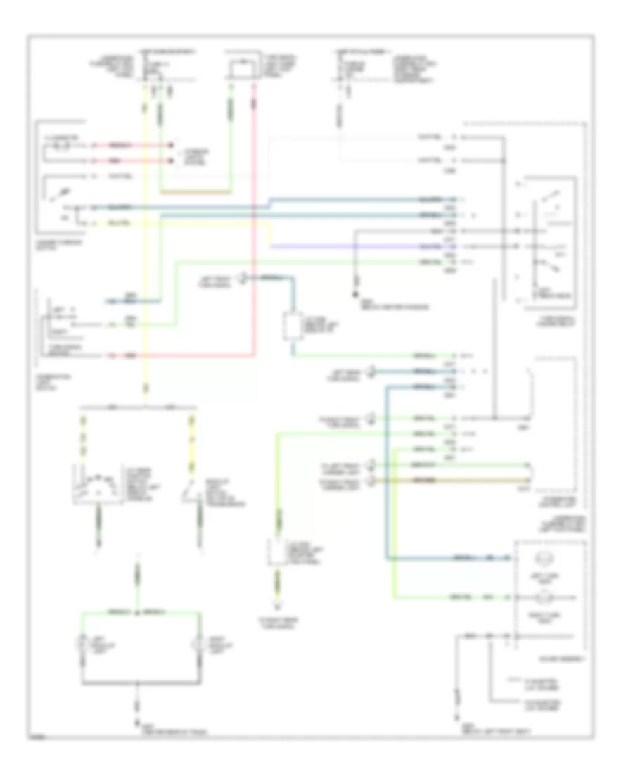
Exterior Light Wiring Diagram (2 of 2) for Honda Prelude 4WS 1994
List of elements for Exterior Light Wiring Diagram (2 of 2) for Honda Prelude 4WS 1994:
- (not removable)
- A/t
- A/t gear position switch (below left side of console)
- B10
- Back-up light switch (on top of transmission)
- C423
- C468
- C469
- C471
- C473
- C523
- C524
- C601
- C909
- C921
- Combination light switch
- Fuse 13 10a
- Fuse 39 hazard 15a
- G300 (below left front seat)
- G302 (below center console)
- G407 (center rear of trunk)
- Gauge assembly
- Hazard warning switch
- Hot at all times
- Hot in on or start
- Illumination
- Integrated control unit
- Interior lights system
- J/c c326 (behind left side of i/p)
- J/c c534 (behind left quarter trim panel)
- Left
- Left back-up light
- Left front turn signal
- Left rear turn signal
- Left turn indic
- M/t
- Off
- Red
- Right
- Right back-up light
- Right turn indic
- To left front marker light
- To right front marker light
- To right front turn signal
- To right rear turn signal
- Turn signal light diode (left kick panel)
- Turn signal switch
- Turn signal/ hazard relay
- Under-dash fuse/relay box (left kick panel)
- Under-hood fuse/relay box (right rear of engine compartment)
- W/ electro- lum. gauges
- W/o electro- lum. gauges
GROUND DISTRIBUTION
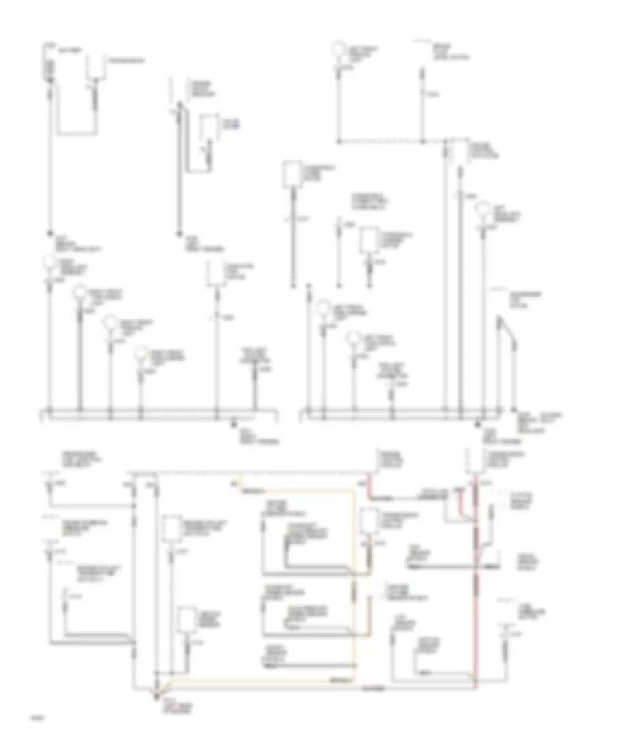
Ground Distribution Wiring Diagram (1 of 4) for Honda Prelude 4WS 1994
List of elements for Ground Distribution Wiring Diagram (1 of 4) for Honda Prelude 4WS 1994:
- (s model only)
- A26
- Battery
- Brake fluid level switch
- C110
- C115
- C118
- C127
- C137
- C206
- C208
- C303
- C308
- C315
- C317
- C318
- C322
- C410
- C443
- C483
- Ckp sensor shield
- Ckp/tdc sensor shield
- Condenser fan motor
- Countershaft speed sensor shield
- Cruise control actuator
- Cyp sensor shield
- Cyp/tdc sensor shield
- Data link connector
- Engine mount bracket
- Engine control module
- Engine coolant temperature switch a
- Engine coolant temperature switch b
- Fog light system connector
- G100 (left front fender)
- G101 (right front fender)
- G106 (behind left headlamp)
- G107 (behind right headlight)
- G114 (left rear of engine)
- Heated oxygen sensor shield
- Knock sensor shield
- Left headlight assembly
- Left front parking light
- Left front side marker light
- Left front turn signal light
- Mainshaft speed sensor shield
- Power steering pressure switch
- Programmed fuel injection main relay
- Radiator fan motor
- Right headlight assembly
- Right front parking light
- Right front side marker light
- Right front turn signal light
- Transmission
- Transmission control module
- Valve cover
- Vehicle speed sensor
- Vtec pressure switch
- Windshield intermittent wiper relay
- Windshield washer motor
- Windshield wiper motor
Ground Distribution Wiring Diagram (2 of 4) for Honda Prelude 4WS 1994
List of elements for Ground Distribution Wiring Diagram (2 of 4) for Honda Prelude 4WS 1994:
- A/t gear position switch
- Abs front fail-safe relay
- Abs pressure switch
- Abs rear fail-safe relay
- C418
- C434
- C436
- C439
- C445
- C457
- C477
- C480
- C481
- C531
- C542
- C552
- C553
- C605
- C606
- C611
- C612
- C616
- C654
- C655
- C724
- C729
- C745
- C747
- C748
- Ceiling light
- Cruise control main switch
- Cruise control unit
- Dash lights brightness control unit
- Daytime running lights control unit (canada)
- Driver's power mirror (canada)
- Driver's power window motor
- Driver's seat belt switch
- Fuel tank unit
- G201 (left side of i/p)
- G308 (left "b" pillar)
- Heater control panel
- High mount brake light
- Interlock control unit
- Left license light
- Main gauge assembly
- Main gauge assembly (with luminescent gauges)
- Main gauge assembly (without luminescent gauges)
- Master power window switch
- Passenger's door lock latch assembly
- Passenger's door lock switch
- Passenger's power mirror (canada)
- Radiator fan control module
- Right license light
- Sub gauge assembly
- Sunroof switch
- Thermistor
- To g300
- To g302
- To under-dash fuse/relay box pin 10
- Trunk latch switch
- Woofer amplifier (vtec,sr-v)
Ground Distribution Wiring Diagram (3 of 4) for Honda Prelude 4WS 1994
List of elements for Ground Distribution Wiring Diagram (3 of 4) for Honda Prelude 4WS 1994:
- Blower motor relay
- C420
- C438
- C440
- C441
- C456 c456
- C458
- C459
- C469
- C471
- C475
- C476
- C482
- C523
- C526
- C527
- C537
- C545
- C575
- C576
- C577
- C578
- C601
- C725
- C730
- C901
- C902
- C903
- C904
- C905
- C909
- C921
- C943
- Chime
- Cigarette lighter
- Cigarette lighter relay
- Clutch interlock switch
- Clutch switch
- Dimmer relay (under-hood fuse/relay box)
- Driver's door lock latch assembly
- Driver's door lock switch
- Driver's seat belt (canada)
- Electrical load detector (under hood fuse/relay box)
- From ceiling light
- From cruise control unit
- From license light
- From master power window switch
- From sunroof switch
- Front main steering angle sensor
- Fuel pump
- G300 (below left front seat)
- G302 (below center console)
- Headlight/ combination light switch
- Heater fan switch
- Horn relay
- Ignition key switch
- Integrated control unit
- Left seat heater (canada)
- Left seat heater relay (canada)
- Left seat heater switch (canada)
- Power door lock control unit
- Power mirror switch
- Power window relay
- Right seat heater (canada)
- Right seat heater relay (canada)
- Seat heater main relay (canada)
- Security system connector
- Stereo radio/ cassette player
- Sunroof close relay
- Sunroof open relay
- Turn signal/ hazard relay
- Under-dash fuse/relay box
- Windshield wiper/washer switch
Ground Distribution Wiring Diagram (4 of 4) for Honda Prelude 4WS 1994
List of elements for Ground Distribution Wiring Diagram (4 of 4) for Honda Prelude 4WS 1994:
- 4ws control unit
- C509
- C510
- C558
- Damper shield
- G203 (right kick panel)
- G305 (right "b" pillar)
- G312 (behind left rear seat)
- G407 (center rear of trunk)
- G415 (center of rear steering actuator)
- High mount brake light
- Left back-up light
- Left brake light/ taillight
- Left brake light failure sensor
- Left rear side marker light
- Left rear turn signal light
- Motor shield
- Power antenna motor
- Right back-up light
- Right brake light/ taillight
- Right rear side marker light
- Right rear turn signal light
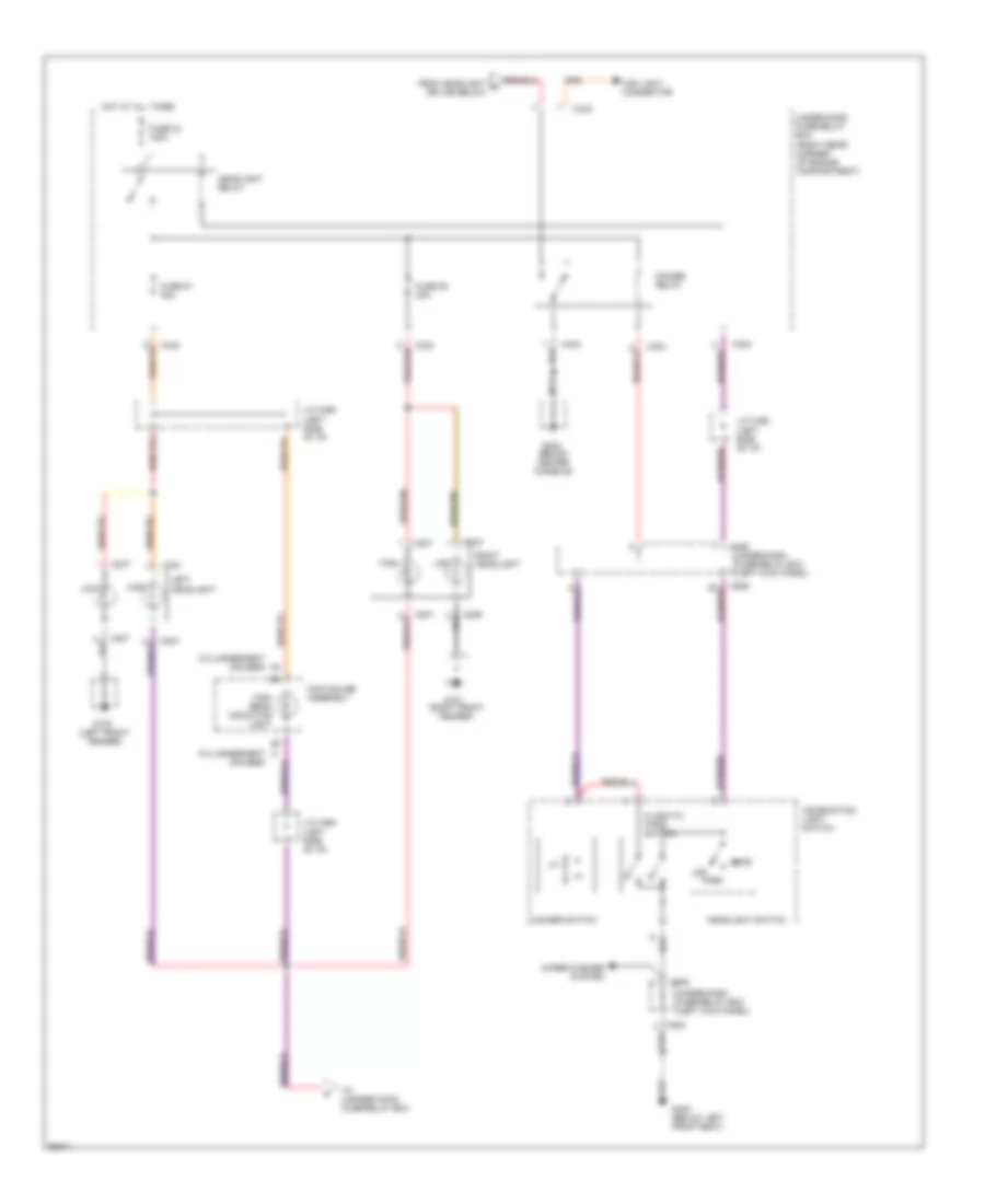
HEADLIGHTS
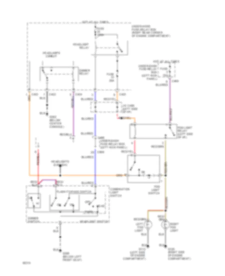
Foglamps for Honda Prelude 4WS 1994
List of elements for Foglamps for Honda Prelude 4WS 1994:
- C422
- C423
- C424
- C468
- C469
- C909
- Combination light switch
- Dimmer relay
- Dimmer switch
- Flash-to-pass switch
- Fog light relay (left side of i/p)
- Fog light switch
- Fuse 100a
- Fuse 15a
- Fuse 20a
- G112 (left side of engine compartment)
- G120 (right side of engine compartment)
- G300 (below left front seat)
- G302 (below center console)
- Head
- Headlamps circuit
- Headlight relay
- Headlight switch
- Headlights (canada)
- Hot at all times
- J/c c460 (left side of i/p)
- Left fog light
- Off
- Park
- Right fog light
- Under-dash fuse-relay box (left kick panel)
- Under-dash fuse/relay box (left kick panel)
- Under-hood fuse-relay box (right rear corner of engine compartment)
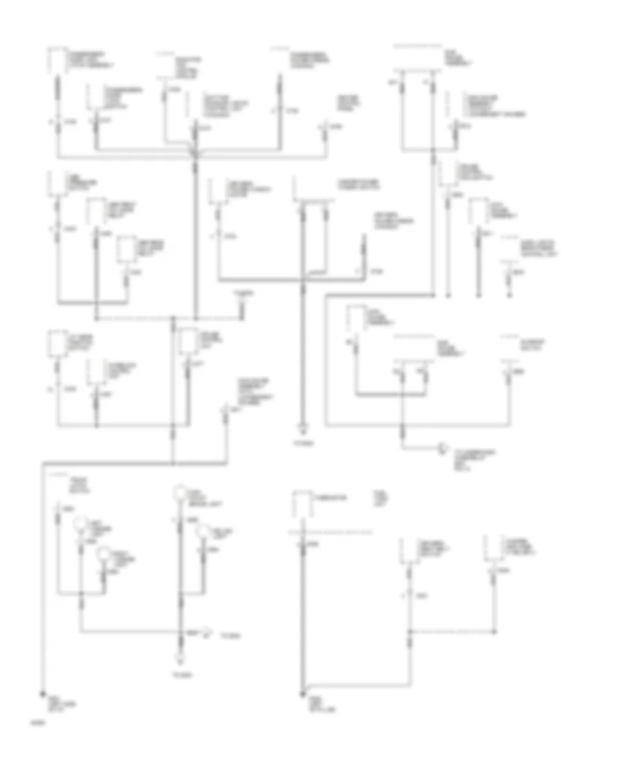
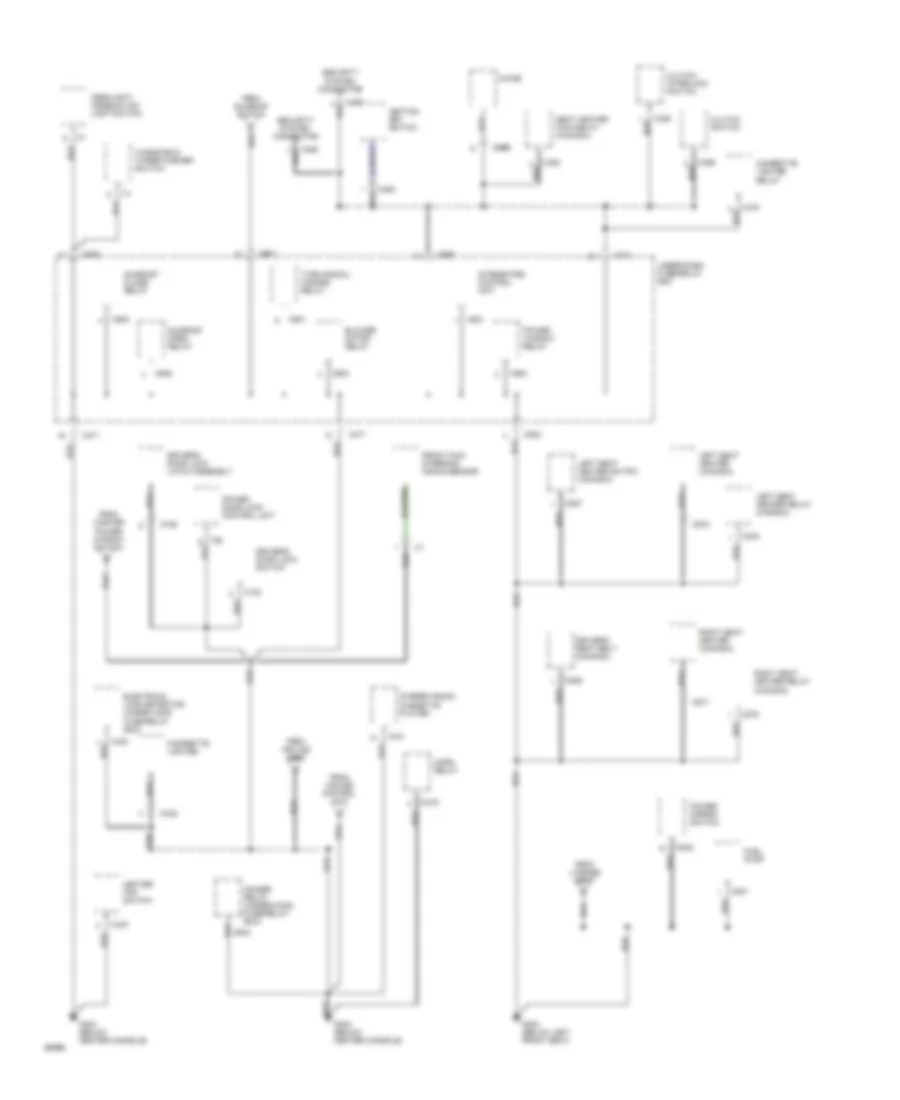
Headlamps Wiring Diagram, with DRL for Honda Prelude 4WS 1994
List of elements for Headlamps Wiring Diagram, with DRL for Honda Prelude 4WS 1994:
- (right rear corner of engine compartment)
- Battery input
- Brake indicator output
- C207
- C209
- C304
- C307
- C422
- C423
- C424
- C468
- C470
- C471
- C523
- C601
- C909
- Combination light switch
- Daytime running lights control unit (right side of dash)
- Daytime running lights indicator
- Dimmer relay
- Dimmer switch
- E18
- Flash-to-pass switch
- From b control unit
- From high beams
- Fuse 12 7.5a
- Fuse 13 10a
- Fuse 32 100a
- Fuse 50 20a
- Fuse 51 20a
- Fuse 8 10a
- G100 (left front fender)
- G101 (right front fender)
- G201 (right side of i/p)
- G300 (below left front seat)
- G302 (below center console)
- Ground
- Head
- Headlight relay
- Headlight switch
- High
- High beam indicator light
- High beam off input
- High beam on input
- Hot at all times
- Hot in on
- Hot in on or start
- Ignition input
- Indicator
- Instrument cluster system
- J/c c460 (left side of i/p)
- J/c c619 (right side of i/p)
- Left headlight
- Left high beam control
- Lights on input
- Lights-on request input
- Low
- Main gauge assembly
- Off
- Park
- Parking brake input
- Parking brake switch (below center console)
- Right headlight
- Right high beam control
- Sub gauge assembly
- To under-hood fuse/relay box
- Under-dash fuse/relay box (left kick panel)
- Under-hood fuse/relay box
- Wiper/washer system
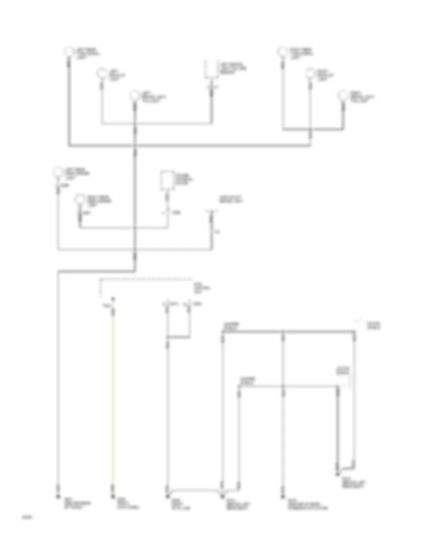
Headlamps Wiring Diagram, without DRL for Honda Prelude 4WS 1994
List of elements for Headlamps Wiring Diagram, without DRL for Honda Prelude 4WS 1994:
- (below center console)
- (left front fender)
- (right front fender)
- (w/luminescent gauges)
- B7 j1
- C207
- C209
- C304
- C307
- C422
- C423
- C424
- C468
- C523
- C909
- Combination light switch
- Dimmer relay
- Dimmer switch
- Flash-to pass switch
- Fog light connector
- From headlight a splice below
- Fuse 32 100a
- Fuse 50 20a
- Fuse 51 20a
- G100
- G101
- G300 (below left front seat)
- G302
- Head
- Headlight relay
- Headlight switch
- High
- High beam indicator light
- Hot at all times
- J/c c460 (left side of i/p)
- Left headlight
- Low
- Main gauge assembly
- Nca
- Off
- Park
- Right headlight
- To unnder-hood fuse/relay box
- Under-dash fuse/relay box (left kick panel)
- Under-hood fuse/relay box (right rear corner of engine compartment)
- Wiper/washer system
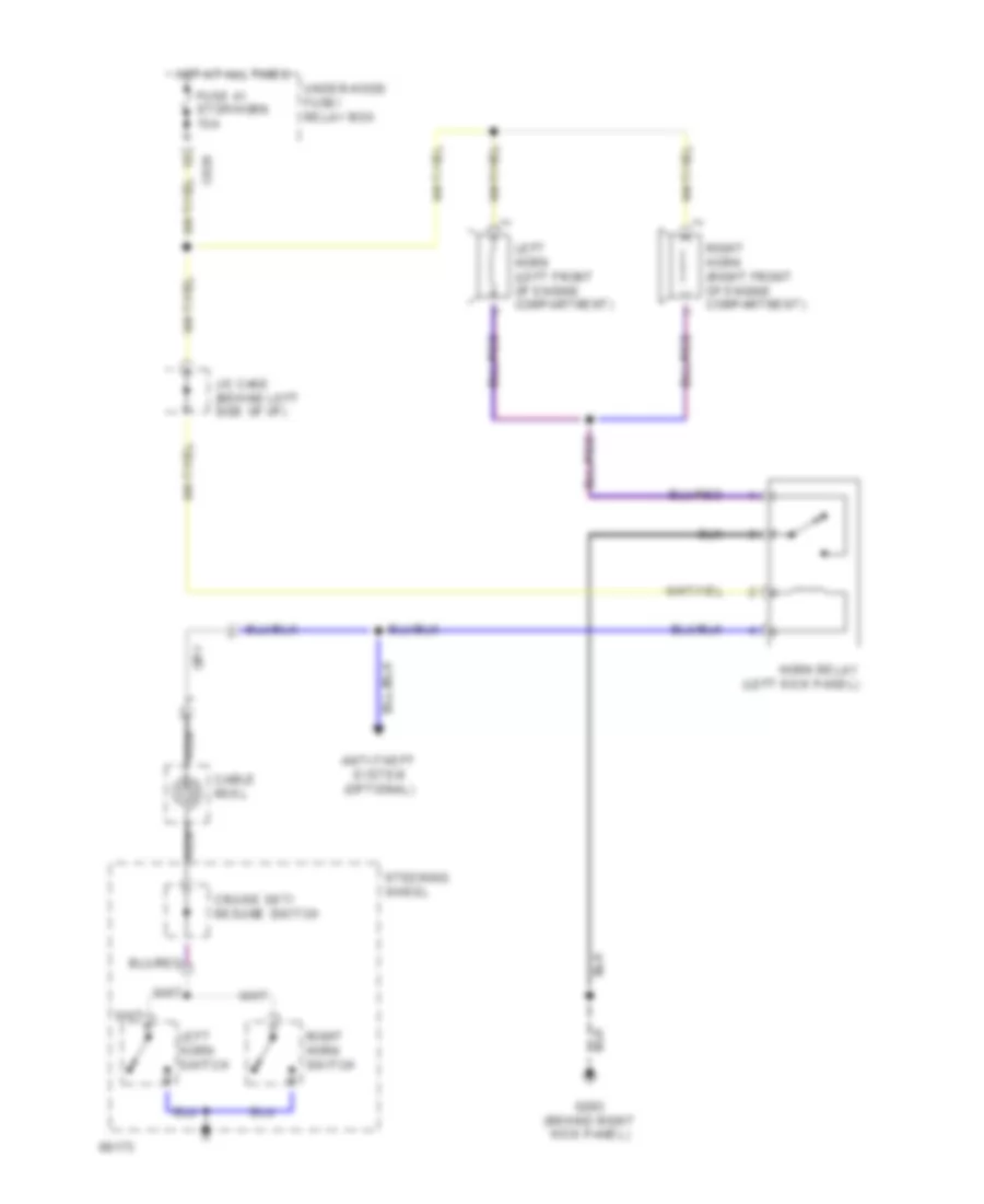
HORN
Horn Wiring Diagram for Honda Prelude 4WS 1994
List of elements for Horn Wiring Diagram for Honda Prelude 4WS 1994:
- Anti-theft system (optional)
- C424
- Cable reel
- Cruise set/ resume switch
- Fuse 41 stop/horn 15a
- G203 (behind right kick panel)
- Horn relay (left kick panel)
- Hot at all times
- J/c c460 (behind left side of i/p)
- Left horn (left front of engine compartment)
- Left horn switch
- Nca
- Right horn (right front of engine compartment)
- Right horn switch
- Steering wheel
- Under-hood fuse/ relay box
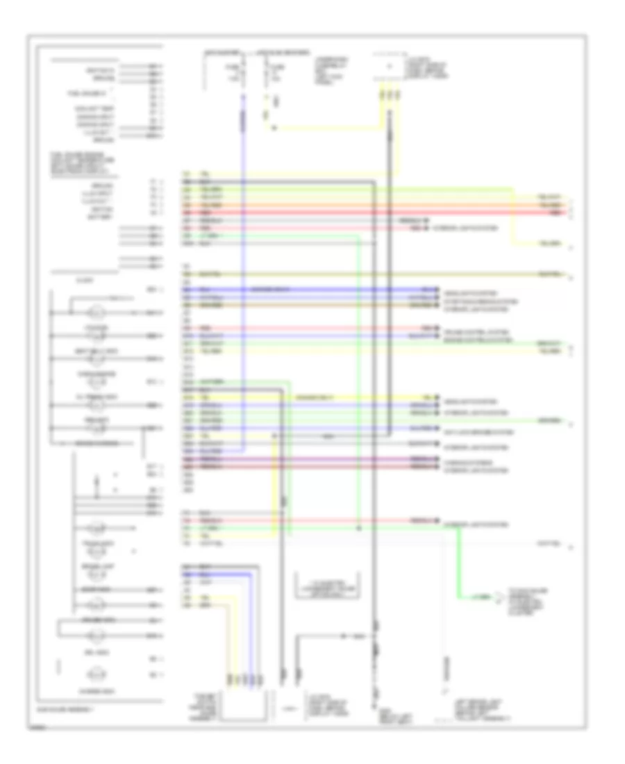
INSTRUMENT CLUSTER
Sub Gauge Assembly Wiring Diagram (1 of 2) for Honda Prelude 4WS 1994
List of elements for Sub Gauge Assembly Wiring Diagram (1 of 2) for Honda Prelude 4WS 1994:
- (canada only)
- * w/ electro- luminescent gauge option only
- 10a
- 7.5a
- Abs indic
- Anti-lock brakes system
- Battery
- Brake lamp
- Brake warning
- C601
- Charge indic
- Check engine
- Clock
- Coolant temp
- Cruise control system
- Cruise indic
- D10
- Dimming input
- Door indic
- Drl indic
- E10
- E11
- E12
- E13
- E14
- E15
- E16
- E17
- E18
- E19
- E20
- E21
- E22
- E23
- E24
- E25
- E26
- E27
- E28
- E29
- E30
- Engine controls system
- Fuel gauge in
- Fuel gauge/ engine coolant temperature (ect) gauge circuit (electronic display)
- Fuse
- G300 (below left front seat)
- Ground
- Headlights system
- Hot in on or start
- Hot in start
- Ignition
- Ignition in
- Illum input
- Illum out *
- Interior lights system
- J/c c619 (right side of dash, behind display visor)
- Left brake light failure sensor (behind left taillight assembly)
- Low fuel
- Nca
- Oil press indic
- Red
- Seat belt indic
- Starting/charging system
- Sub gauge assembly
- Time set switch (near sub- gauge assembly)
- To main gauge assembly (w/ electro- luminescent cluster)
- Trunk indic
- Under-dash fuse/relay box (left kick panel)
- Warning systems
Sub Gauge Assembly Wiring Diagram (2 of 2) for Honda Prelude 4WS 1994
List of elements for Sub Gauge Assembly Wiring Diagram (2 of 2) for Honda Prelude 4WS 1994:
- 10a
- 15a
- Anti-lock brakes system & electronic power steering system (4ws control unit)
- Brake fluid level switch (master cylinder)
- C418
- C422
- C473
- C601
- Canada
- Drl control module (behind right side of i/p)
- Engine coolant temperature (ect) sending unit (right side of engine)
- Engine oil pressure switch (center rear under- side of engine)
- Fuel tank unit (top of fuel tank)
- Fuse
- Fuse 43 clock/radio
- G101 (left front fender apron)
- G308 (left 'b' pillar)
- Hot at all times
- Hot in on or start
- Integrated control unit
- J/c c326 (above left kick panel)
- J/c c447 (behind left side of i/p)
- Parking brake switch (below center console)
- Red
- S only
- Srs fuse block
- Si, sr, 4ws, vtec & sr-v
- Thermistor
- Under-dash fuse/relay box (left kick panel)
- Under-hood fuse/relay box (right rear of engine compartment)
- Usa
Sub Gauge Assembly Wiring Diagram, with Electro-Luminescent Gauges (1 of 2) for Honda Prelude 4WS 1994
List of elements for Sub Gauge Assembly Wiring Diagram, with Electro-Luminescent Gauges (1 of 2) for Honda Prelude 4WS 1994:
- 10a
- 4ws indic
- C422
- C601
- Dc/ac inverter (left side of main gauge assembly)
- Electronic power steering (4ws control unit)
- Engine controls system, transmissions system
- Exterior lights system
- From sub-gauge assembly
- Fuse
- Fuse 43 clock/radio
- G201 (left side of i/p)
- G302 (below center console)
- H10
- Headlights system
- High beam
- Hot at all times
- Hot in on or start
- Interior lights system
- J/c c419 (behind right i/p)
- J/c c619 (right side of dash, behind display visor)
- Left turn
- Main gauge assembly
- Nca
- Pnk
- R10
- R11
- R12
- R13
- R14
- Right turn
- Srs indic
- Srs indicator driver & dimmer control circuits
- T10
- To main gauge assembly
- Transmissions system
- Under-dash fuse/relay box (left kick panel)
- Under-hood fuse/relay box (right rear of engine compartment)
Sub Gauge Assembly Wiring Diagram, with Electro-Luminescent Gauges (2 of 2) for Honda Prelude 4WS 1994
List of elements for Sub Gauge Assembly Wiring Diagram, with Electro-Luminescent Gauges (2 of 2) for Honda Prelude 4WS 1994:
- (not used)
- 15a
- A/t gear position switch (under center console)
- C467
- C469
- C471
- C601
- Cruise control system
- Dc/ac inverter (left side of main gauge assembly)
- Dimming input
- Electronic power steering system (4ws control unit)
- Engine controls system
- From main gauge assembly
- Fuse
- G114 (left rear of engine)
- G201 (behind right side of i/p)
- Ground
- Heater ground
- Hot in on or start
- Ignition control module (icm) (top right side of engine, in distributor)
- J/c c131 (right rear of engine compartment)
- J/c c419 (behind right side of i/p)
- Main gauge assembly
- Odo/tripmeter power
- Speedometer/ odometer/ tachometer electronic module
- Srs fuse block
- Tach test connector (right side of engine compartment)
- Tachometer signal input
- Transmissions system
- Under-dash fuse/relay box (left kick panel)
- Vehicle speed sensor (vss) (right side of transmission)
- Vss input
Sub Gauge Assembly Wiring Diagram, without Electro-Luminescent Gauges for Honda Prelude 4WS 1994
List of elements for Sub Gauge Assembly Wiring Diagram, without Electro-Luminescent Gauges for Honda Prelude 4WS 1994:
- (not used)
- 10a
- 15a
- A/t gear position switch (under center console)
- A10
- A11
- A12
- A13
- A14
- A15
- A16
- B10
- C467
- C469
- C471
- C601
- Cruise control system
- Engine controls & transmissions systems
- Engine controls system
- Exterior lights system
- Fuse
- G114 (left rear of engine)
- G201 (behind right side of i/p)
- G300 (below left front seat)
- Headlights system
- High beam
- Hot in on or start
- Ignition control module (icm) (top right side of engine, in distributor)
- Illumination
- Interior lights system
- J/c c131 (right rear of engine compartment)
- J/c c419 (behind right side of i/p)
- J/c c619 (right side of dash, behind display visor)
- Left turn
- Main gauge assembly
- Nca
- Red
- Right turn
- Speedometer/ odometer
- Srs fuse block
- Srs indic
- Srs indicator driver & dimmer control circuits
- Tach test connector (right side of engine compartment)
- Tachometer
- Transmissions system
- Under-dash fuse/relay box (left kick panel)
- Vehicle speed sensor (vss) (right side of transmission)
INTERIOR LIGHTS
Courtesy Lamp Wiring Diagram for Honda Prelude 4WS 1994
List of elements for Courtesy Lamp Wiring Diagram for Honda Prelude 4WS 1994:
- Anti-theft system (optional)
- C424
- C470
- C523
- C601
- Ceiling light
- Ceiling lights
- Door
- Door locks system
- Driver's door switch
- E19
- E24
- Fuse 46 interior lights 15a
- G300 (below left front seat)
- G302 (below center console)
- Hot at all times
- Instrument clusters system
- J/c c534 (behind left quarter trim panel)
- Off
- Pass- enger's door switch
- Spot- lights
- Sub-gauge assembly
- Trunk latch switch
- Trunk light
- Under-dash fuse/relay box (left kick panel)
- Under-hood fuse/relay box (right rear of engine compartment)
- W/ roof spotlights
- W/o roof spotlights
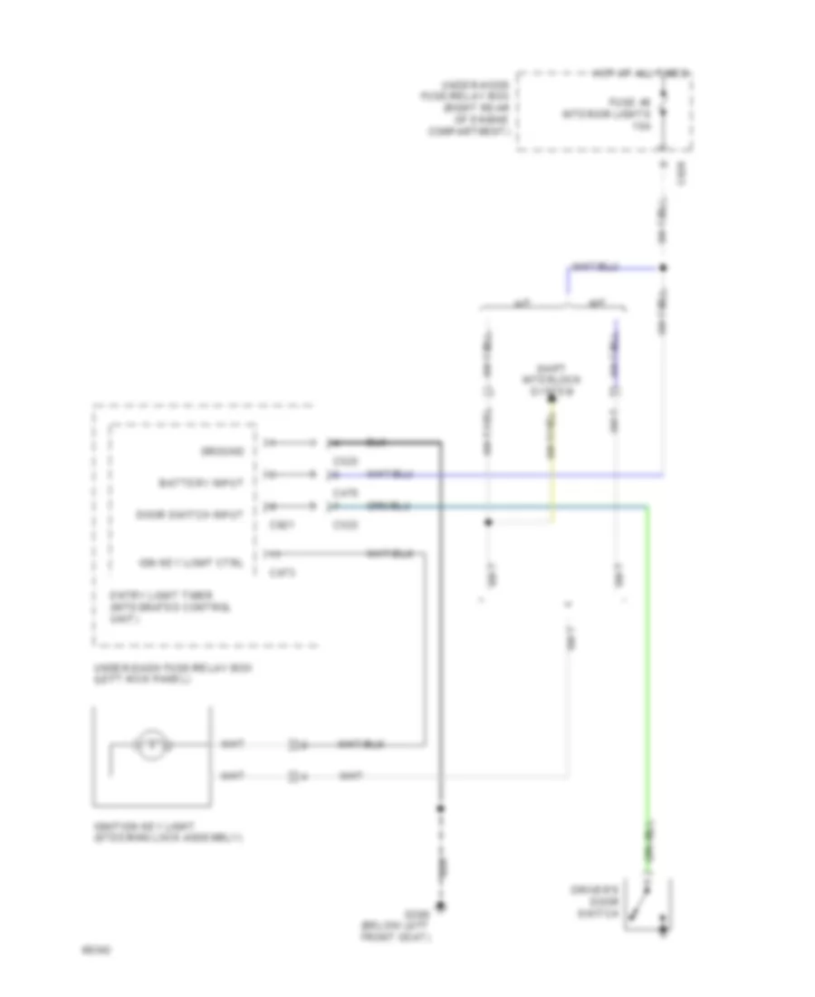
Ignition Key Light Wiring Diagram for Honda Prelude 4WS 1994
List of elements for Ignition Key Light Wiring Diagram for Honda Prelude 4WS 1994:
- A/t
- Battery input
- C424
- C470
- C473
- C523
- C921
- Door switch input
- Driver's door switch
- Entry light timer (integrated control unit)
- Fuse 46 interior lights 15a
- G300 (below left front seat)
- Ground
- Hot at all times
- Ign key light ctrl
- Ignition key light (steering lock assembly)
- M/t
- Shift interlock system
- Under-dash fuse/relay box (left kick panel)
- Under-hood fuse/relay box (right rear of engine compartment)
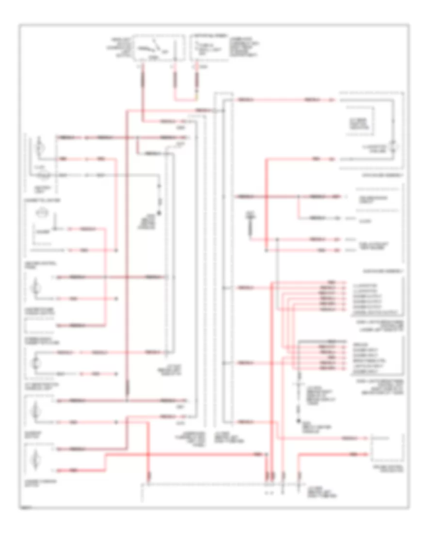
Instrument Illumination Wiring Diagram, with Electro-Luminescent Gauges for Honda Prelude 4WS 1994
List of elements for Instrument Illumination Wiring Diagram, with Electro-Luminescent Gauges for Honda Prelude 4WS 1994:
- (not used)
- A/t gear position console light
- A/t gear position indicator
- Ashtray light
- C424
- C470
- C601
- C909
- Cancel switch output
- Cigarette lighter
- Clock
- Cruise control main switch
- Cruise dimming circuit
- Dash lights brightness control unit (right side of i/p, behind display visor)
- Dash lights brightness controller (under left side of i/p)
- Dimmer
- Dimming input
- Dimming output
- E27
- Fuel & coolant temp gauges
- Fuse 10a
- Fuse 42 small light 20a
- G302 (below center console)
- Gauges
- Ground
- Hazard warning switch
- Head
- Headlight switch (combination light switch)
- Heater control panel
- Hot at all times
- Hot in on or start
- Illum.
- Illumination
- In-line diode 1
- In-line diode 2
- J/c c447 (behind left side of i/p)
- J/c c609 (behind left dash tweeter)
- J/c c619 (behind right side of i/p, behind display visor)
- Main gauge assembly
- Master power window switch
- Off
- Park
- Red
- Stereo radio/ cassette player
- Sub gauge assembly
- Sunroof switch
- Under-dash fuse/relay box (left kick panel)
- Under-hood fuse/relay box (right rear of engine compartment)
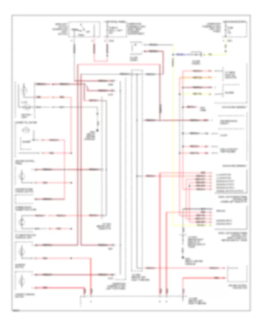
Instrument Illumination Wiring Diagram, without Electro-Luminescent Gauges for Honda Prelude 4WS 1994
List of elements for Instrument Illumination Wiring Diagram, without Electro-Luminescent Gauges for Honda Prelude 4WS 1994:
- (not used)
- A/t gear position console light
- A/t gear position indicator
- Ashtray light
- Brightness ctrl
- C424
- C470
- C601
- C909
- Cancel switch output
- Cigarette lighter
- Clock
- Cruise control main switch
- Cruise dimming circuit
- Dash lights brightness control unit (right side of i/p, behind display visor)
- Dash lights brightness controller (under left side of i/p)
- Dimmer
- Dimmer input
- Dimmer output
- E27
- Fuel & coolant temp gauges
- Fuse 42 small light 20a
- G302 (below center console)
- Ground
- Hazard warning switch
- Head
- Headlight switch (combination light switch)
- Heater control panel
- Hot at all times
- Illum.
- Illumination
- Illumination (5 bulbs)
- J/c c447 (behind left side of i/p)
- J/c c609 (behind left dash tweeter)
- J/c c619 (behind right side of i/p, behind display visor)
- Lights on input
- Main gauge assembly
- Master power window switch
- Off
- Park
- Red
- Stereo radio/ cassette player
- Sub gauge assembly
- Sunroof switch
- Under-dash fuse/relay box (left kick panel)
- Under-hood fuse/relay box (right rear of engine compartment)
POWER ANTENNA
Power Antenna Wiring Diagram for Honda Prelude 4WS 1994
List of elements for Power Antenna Wiring Diagram for Honda Prelude 4WS 1994:
- 1995 vftc c
- C422
- C441
- C471
- Fuse 10a
- Fuse 43 clock/radio 10a
- G407 (center rear of trunk)
- Hot at all times
- Hot in acc or run
- J/c c419 (behind right side of i/p)
- Limit switches
- Off
- Power antenna motor (right side of trunk)
- Power antenna relay
- Stereo radio/ cassette player
- Under-dash fuse/relay box (left kick panel)
- Under-hood fuse/relay box (right rear of engine compartment)
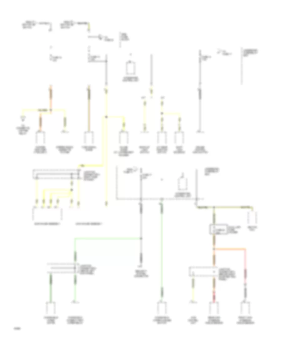
POWER DISTRIBUTION
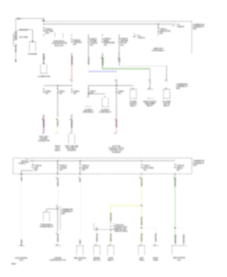
Power Distribution Wiring Diagram (1 of 5) for Honda Prelude 4WS 1994
List of elements for Power Distribution Wiring Diagram (1 of 5) for Honda Prelude 4WS 1994:
- 4ws control unit
- Abs control unit
- Abs pump motor relay
- Alternator
- Battery
- Blower motor relay
- Brake switch
- Daytime running lights control unit (canada)
- Electrical load detector (eld) unit
- Fog light system connector
- From a fuse 31
- Fuse 3 15a
- Fuse 31 abs motor 50a
- Fuse 32 battery 100a
- Fuse 34 rear defroster 40a
- Fuse 35 heater motor 40a
- Fuse 36 fuse box 40a
- Fuse 37 power window 40a
- Fuse 38 4ws 60a
- Fuse 39 hazard 15a
- Fuse 4 10a
- Fuse 40 abs b2 15a
- Fuse 41 stop,horn 15a
- Fuse 49 abs b1 20a
- Fuse 6 15a
- Fuse 7 30a
- Fuse 8 10a
- Hazard warning switch
- Horn relay
- Junction connector 7 (behind left side of dash)
- Left horn
- Pgm-fi main relay
- Power window relay
- Rear window defogger relay
- Right horn
- Seat heater main relay (canada)
- Starter
- Sunroof close relay
- Sunroof open relay
- To fuse 33
- To fuse 38
- Turn signal/ hazard relay
- Underdash fuse/relay box
- Underhood fuse/relay box
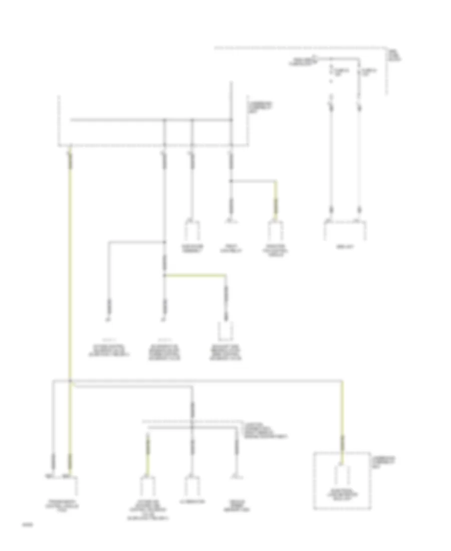
Power Distribution Wiring Diagram (2 of 5) for Honda Prelude 4WS 1994
List of elements for Power Distribution Wiring Diagram (2 of 5) for Honda Prelude 4WS 1994:
- 4ws control unit
- A/c compressor clutch relay
- A/c thermostat
- A/t
- A/t gear position switch
- Abs control unit
- Abs front fail-safe relay
- Abs inspection connector
- Abs pump motor relay
- Acc
- Blower motor relay
- Canada
- Daytime running lights control unit (canada)
- From b fuse 35
- Fuse 11 10a
- Fuse 12 7.5a
- Fuse 33 ig sw 50a
- Fuse 9 15a
- Heater control panel
- Ignition switch
- Junction connector 1 (behind right side of dash)
- Junction connector 2 (behind left side of dash)
- Junction connector 3 (behind right quarter trim panel)
- Lock
- M/t
- Mode control motor
- Power mirror switch
- Radiator fan control module
- Recirculation control motor
- Run
- S only
- Seat heater main relay (canada)
- Srs fuse block
- Start
- Starter cut relay
- To fuse 42
- To srs fuse block
- Underdash fuse/relay box
- Underhood fuse/relay box
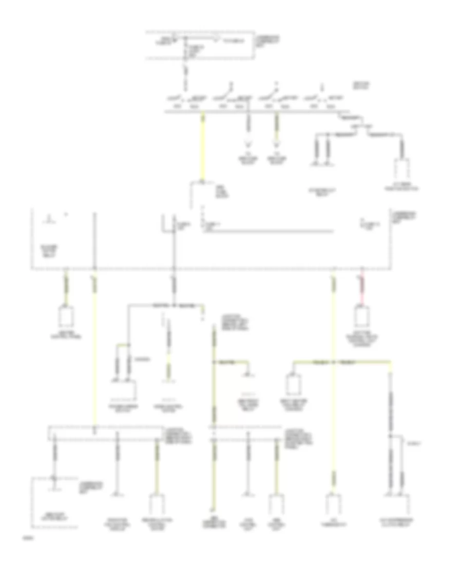
Power Distribution Wiring Diagram (3 of 5) for Honda Prelude 4WS 1994
List of elements for Power Distribution Wiring Diagram (3 of 5) for Honda Prelude 4WS 1994:
- 4ws control unit
- A/c compressor clutch relay (si,sr,4ws, vtec,sr-v)
- A/t
- Celing light
- Cigarette lighter
- Cigarette lighter relay (left kick panel)
- Combination light switch
- Condenser fan relay
- Data link connector
- Engine control module (ecm)
- From e fuse 45
- From fuse 18 (underdash fuse/relay box)
- From h fuse 33
- Fuse 42 small light 20a
- Fuse 43 clock/ radio 10a
- Fuse 44 door lock 15a
- Fuse 45 condenser fan 15a
- Fuse 46 interior lights 15a
- Fuse 47 cooling fan 15a
- G206 (under center of i/p)
- G300 (left side of floor)
- Headlight relay
- Ignition key light
- Integrated control unit
- Junction connector 1 (behind right side of dash)
- Junction connector 8 (behind left quarter trim panel)
- Key interlock switch
- M/t
- Main gauge assembly (w/ luminescent gauges)
- Power antenna motor
- Power door lock control unit
- Radiator fan control motor
- Radiator fan relay
- Security system connector
- Si,sr,4ws, vtec,sr-v
- Stereo radio/ cassette player
- Sub gauge assembly
- To fuse 46
- Transmission control module (tcm)
- Trunk light
- Underdash fuse/relay box
- Underhood fuse/relay box
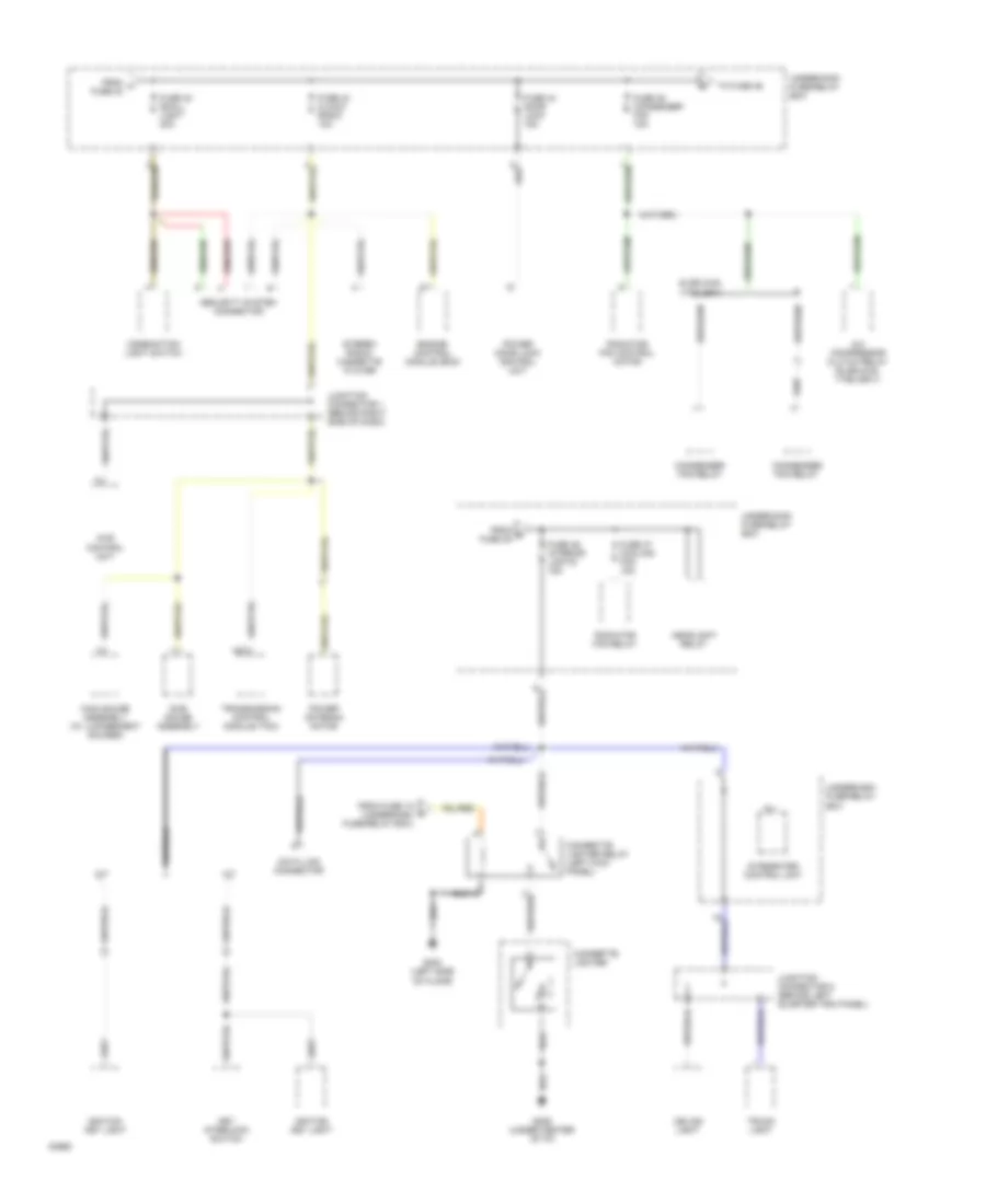
Power Distribution Wiring Diagram (4 of 5) for Honda Prelude 4WS 1994
List of elements for Power Distribution Wiring Diagram (4 of 5) for Honda Prelude 4WS 1994:
- 4ws control unit
- A/t
- A/t gear position switch
- Auxillary fuse holder
- Back-up light switch
- Cruise control main switch
- From h fuse 14
- From ignition switch
- Front main steering angle sensor
- Fuse 13 10a
- Fuse 14 7.5a
- Fuse 17 30a
- Fuse 18 10a
- Fuse 22 10a
- Ignition coil
- In-line diode (w/ luminescent gauges)
- Integrated control unit
- Junction connector 3 (behind right quarter trim panel)
- Junction connector 4 (right side of dash)
- Junction connector 5 (above left kick panel)
- M/t
- Main gauge assembly
- Rear main steering angle sensor
- Red
- Security system connector
- Shift lock solenoid
- Srs fuse block
- Stereo radio/ cassette player
- Sub gauge assembly
- To cigarette lighter relay
- To fuse 17
- To fuse 23
- Turn signal diode
- Underdash fuse/relay box
- Windshield intermittent wiper relay
- Windshield wiper motor
- Windshield wiper/washer switch
- Woofer amplifier (vtec,sr-v)
Power Distribution Wiring Diagram (5 of 5) for Honda Prelude 4WS 1994
List of elements for Power Distribution Wiring Diagram (5 of 5) for Honda Prelude 4WS 1994:
- A23
- A24
- Alternator
- Electrical load detector (eld) unit
- Evaporative emission (evap) purge control solenoid valve
- Exhaust gas recirculation (egr) control solenoid valve
- From srs g fuse block
- Fuse 23 15a
- Fuse 24 10a
- Intake air bypass (iab) control solenoid valve (si,sr,4ws,vtec,sr-v)
- Intake control solenoid valve (si,sr,4ws,vtec,sr-v)
- Junction connector 6 (right rear of engine compartment)
- Nca
- Pgm-fi main relay
- Radiator fan control module
- Srs fuse block
- Srs unit
- Sub gauge assembly
- Transmission control module (tcm)
- Underdash fuse/relay box
- Underhood fuse/relay box
- Vehicle speed sensor (vss)
POWER DOOR LOCKS
Power Door Lock Wiring Diagram for Honda Prelude 4WS 1994
List of elements for Power Door Lock Wiring Diagram for Honda Prelude 4WS 1994:
- 15a
- 1995 vftc c
- Anti-theft system (optional)
- Battery input
- C422
- C523
- C601
- C726
- Driver's door lock latch assembly
- Driver's door lock switch
- Driver's door switch
- Driver's door switch input
- Driver's lock input
- Driver's unlock input
- Fuse 44 door lock
- G201 (behind left side of i/p)
- G300 (below left front seat)
- G302 (below center console)
- Ground
- Hot at all times
- Ignition key switch
- Ignition key switch input
- J/c c460 (behind left side of i/p)
- Lock
- Lock input
- Lock output
- Passenger's door lock latch assembly
- Passenger's door lock switch
- Passenger's door switch
- Passenger's door switch in
- Power door lock control unit (inside driver's door)
- Under-dash fuse/relay box (left kick panel)
- Under-hood fuse/relay box (right rear of engine compartment)
- Unlock
- Unlock input
- Unlock output
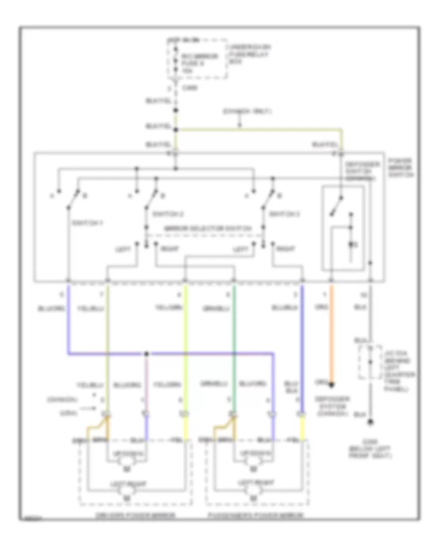
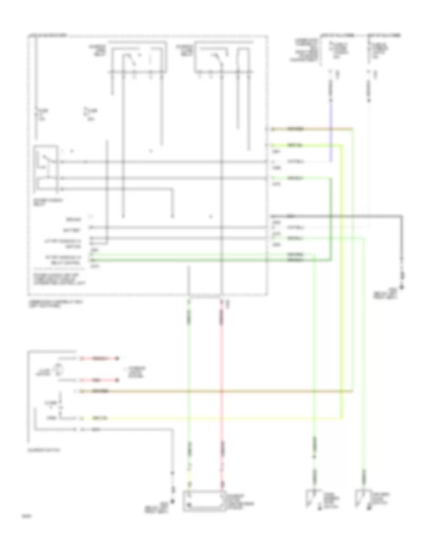
POWER MIRRORS
Power Mirror Wiring Diagram for Honda Prelude 4WS 1994
List of elements for Power Mirror Wiring Diagram for Honda Prelude 4WS 1994:
- (canada only)
- (canada)
- (usa)
- C468
- Defogger switch (canada)
- Defogger system (canada)
- Driver's power mirror
- G300 (below left front seat)
- Hot in on
- J/c 534 (behind left quarter trim panel)
- Left
- Left/right
- Mirror selector switch
- Passenger's power mirror
- Power mirror switch
- R/c mirror fuse 9 15a
- Right
- Switch 1
- Switch 2
- Switch 3
- Under-dash fuse/relay box
- Up/down
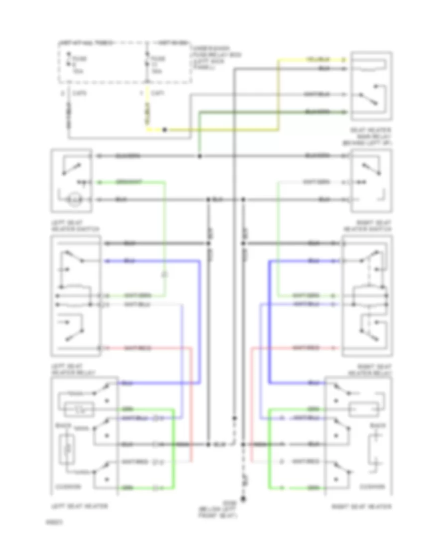
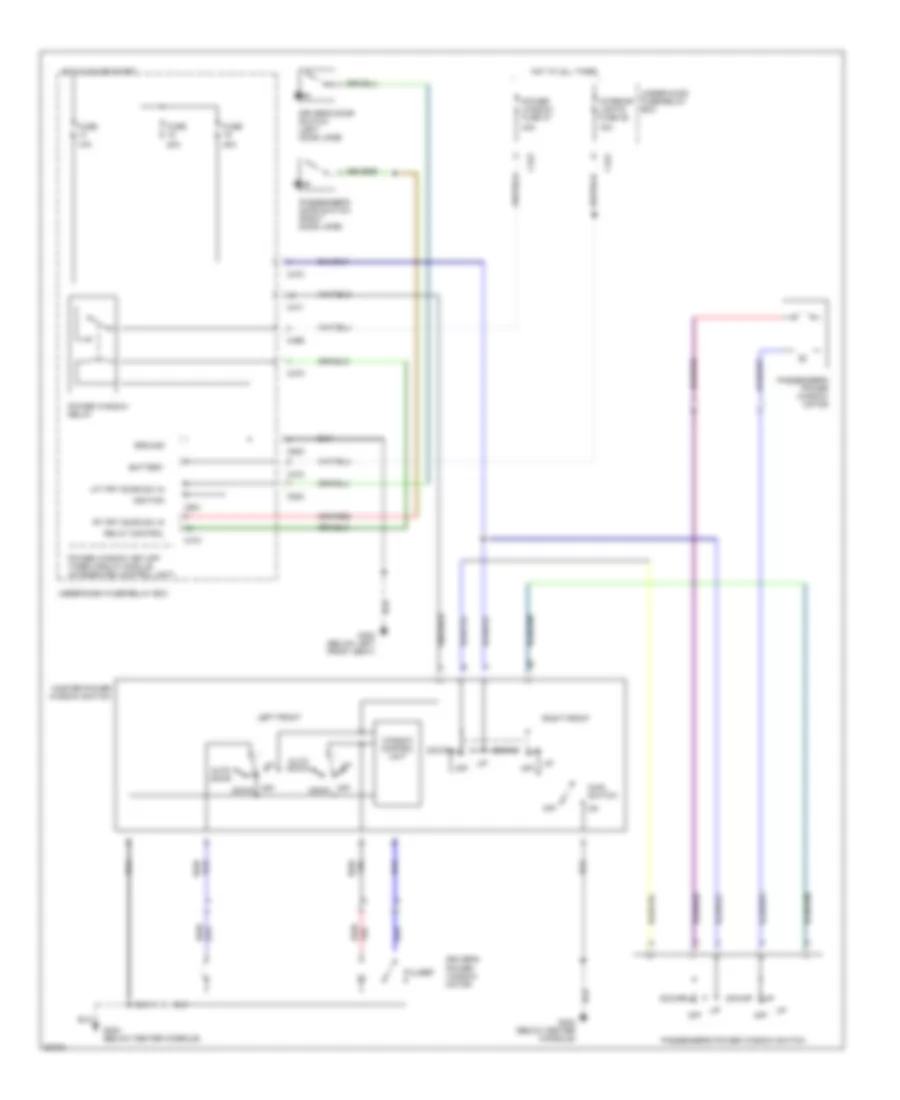
POWER SEATS
Heated Seats Wiring Diagram, Canada for Honda Prelude 4WS 1994
List of elements for Heated Seats Wiring Diagram, Canada for Honda Prelude 4WS 1994:
- Back
- C470
- C471
- Cushion
- Fuse 10a
- Fuse 15a
- G300 (below left front seat)
- Hot at all times
- Hot in on
- Left seat heater
- Left seat heater relay
- Left seat heater switch
- Nca
- Right seat heater
- Right seat heater relay
- Right seat heater switch
- Seat heater main relay (behind left i/p)
- Under-dash fuse/relay box (left kick panel)
POWER TOP/SUNROOF
Sunroof Wiring Diagram for Honda Prelude 4WS 1994
List of elements for Sunroof Wiring Diagram for Honda Prelude 4WS 1994:
- 10a
- 15a
- 30a
- 40a
- Battery
- C422
- C424
- C466
- C470
- C473
- C523
- C601
- C921
- Close
- Driver's door switch
- Fuse
- Fuse 37 power window
- Fuse 46 interior lights
- G300 (below left front seat)
- Ground
- Hot at all times
- Hot in on or start
- Ignition
- Illum- ination
- Interior lights system
- Lft frt door sw in
- Open
- Pass- enger's door switch
- Power window key-off timer circuit module (integrated control unit)
- Power window relay
- Red
- Relay control
- Rt frt door sw in
- Sunroof close relay
- Sunroof motor (center rear of roof)
- Sunroof open relay
- Sunroof switch
- Under-dash fuse/relay box (left kick panel)
- Under-hood fuse/relay box (right rear of engine compartment)
POWER WINDOWS
Power Window Wiring Diagram for Honda Prelude 4WS 1994
List of elements for Power Window Wiring Diagram for Honda Prelude 4WS 1994:
- 10a
- 15a
- 20a
- 40a
- Auto down
- Battery
- C422
- C424
- C466
- C470
- C471
- C473
- C523
- C921
- Down
- Driver's door switch (left door jamb)
- Driver's power window motor
- Fuse
- G300 (below left front seat)
- G302 (below center console)
- Ground
- Hot at all times
- Hot in on or start
- Ignition
- Interior lights fuse 46
- Left front
- Lft frt door sw in
- Main switch
- Master power window switch
- Off
- Passenger's door switch (right door jamb)
- Passenger's power window motor
- Passenger's power window switch
- Power window fuse 37
- Power window key-off timer circuit module (integrated control unit)
- Power window relay
- Pulser
- Red/
- Relay control
- Right front
- Rt frt door sw in
- Under-dash fuse/relay box
- Under-hood fuse/relay box
- Window control unit
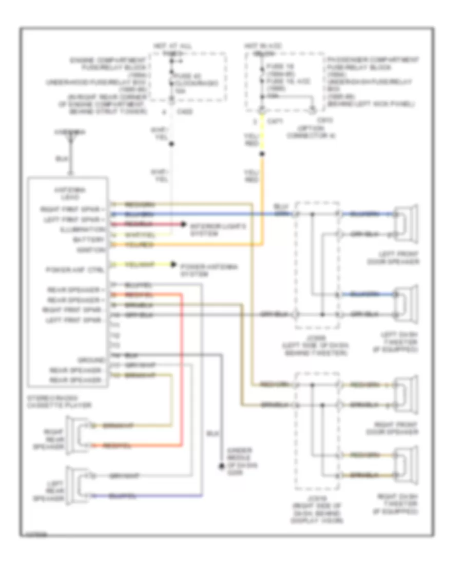
RADIO
Radio Wiring Diagrams, Base Radio for Honda Prelude 4WS 1994
List of elements for Radio Wiring Diagrams, Base Radio for Honda Prelude 4WS 1994:
- (option connector 4)
- (under middle of dash) g206
- Antenna
- Antenna lead
- Battery
- C422
- C471
- C913
- Engine compartment fuse/relay block (1994) under-hood fuse/relay box (1995-96) (in right rear corner of engine compartment, behind strut tower)
- Fuse 18 (1994-95) fuse 18, acc (1996) 10a
- Fuse 43 clock/radio 10a
- Ground
- Hot at all times
- Hot in acc or on
- Ignition
- Illumination
- Interior lights system
- Jc609 (left side of dash, behind tweeter)
- Jc619 (right side of dash, behind display visor)
- Left dash tweeter (if equipped)
- Left frnt spkr +
- Left frnt spkr -
- Left front door speaker
- Left rear speaker
- Passenger compartment fuse/relay block (1994) under-dash fuse/relay box (1995-96) (behind left kick panel)
- Power ant ctrl
- Power antenna system
- Rear speaker +
- Rear speaker -
- Right dash tweeter (if equipped)
- Right frnt spkr +
- Right frnt spkr -
- Right front door speaker
- Right rear speaker
- Stereo radio/ cassette player
Radio Wiring Diagrams, Premium Radio for Honda Prelude 4WS 1994
List of elements for Radio Wiring Diagrams, Premium Radio for Honda Prelude 4WS 1994:
- (behind left quarter trim panel) g414
- (option connector 4)
- (under middle of dash) g206
- Antenna
- Antenna lead
- Battery
- C422
- C471
- C913
- Engine compartment fuse/relay block (1994) under-hood fuse/relay box (1995-96) (in right rear corner of engine compartment, behind strut tower)
- Fuse 18 (1994-95) fuse 18, acc (1996) 1oa
- Fuse 43 clock/radio 10a
- Ground
- Hot at all times
- Hot in acc or on
- Ignition
- Illumination
- Interior lights system
- J/c 534 (behind left quarter trim panel)
- J/c 543 (left side of floor, near doorsill)
- J/c 609 (left side of dash, behind tweeter)
- J/c 619 (right side of dash, behind display visor)
- Left dash tweeter
- Left frnt spkr +
- Left frnt spkr -
- Left front door speaker
- Left rear speaker
- Passenger compartment fuse/relay block (1994) under-dash fuse/relay box (1995-96) (behind left kick panel)
- Power antenna system
- Radio on output
- Rear speaker +
- Rear speaker -
- Red
- Right dash tweeter
- Right frnt spkr +
- Right frnt spkr -
- Right front door speaker
- Right rear speaker
- Stereo radio/ cassette player
- Woofer amplifier
- Woofer speaker
SHIFT INTERLOCKS
Shift Interlock Wiring Diagram for Honda Prelude 4WS 1994
List of elements for Shift Interlock Wiring Diagram for Honda Prelude 4WS 1994:
- A/t gear position switch
- A18
- Brake switch (left i/p)
- C424
- C469
- Cruise control system
- Engine control system
- Fuse 10a
- Fuse 15a
- G201 (right side of i/p)
- Hot at all times
- Hot in on or start
- Interior lights system
- Interlock control unit (right side of i/p)
- J/c
- J/c c460 (left side of i/p)
- Key interlock solenoid
- Key interlock switch
- Shift lock solenoid (right side of front console)
- Throttle position sensor (center rear of engine)
- Transmission control module (right front floor)
- Transmission system
- Under-dash fuse/relay box (left kick panel)
- Under-hood fuse/relay box (right rear corner of engine compartment)
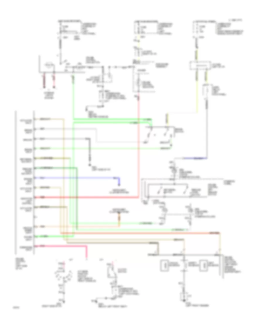
STARTING/CHARGING
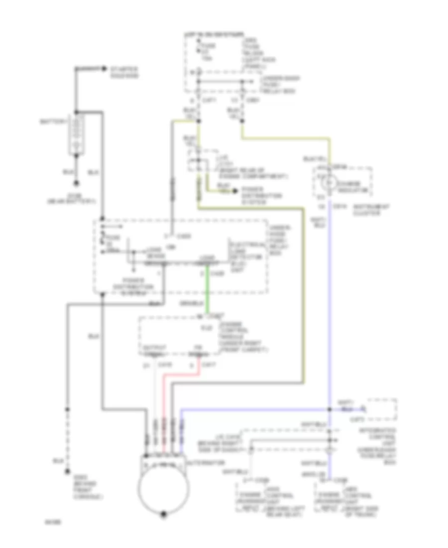
Charging Wiring Diagram for Honda Prelude 4WS 1994
List of elements for Charging Wiring Diagram for Honda Prelude 4WS 1994:
- (4ws)
- (near battery)
- 4ws control unit (behind left rear seat)
- Abs control unit (right side of trunk)
- Alternator
- Battery
- C415
- C417
- C420
- C471
- C473
- C506
- C509
- C601
- C614
- Charge indicator
- Eld
- Electrical load detector (eld) unit
- Engine control module (under right front carpet)
- Engine running input
- Fr signal
- Fuse 100a
- Fuse 15a
- G109
- G302 (behind front console)
- Ground
- Hot in on or start
- Ign
- Instrument cluster
- Integrated control unit (under-dash fuse/relay box
- J/c c131 (right rear of engine compartment)
- J/c c419 (behind right side of dash)
- Load
- Load sense
- Output
- Output signal
- Power distribution system
- Srs fuse block (left kick panel)
- Starter solenoid
- Under- hood fuse/ relay box
- Under-dash fuse/ relay box
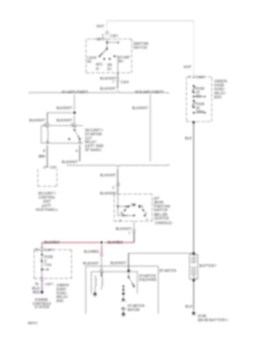
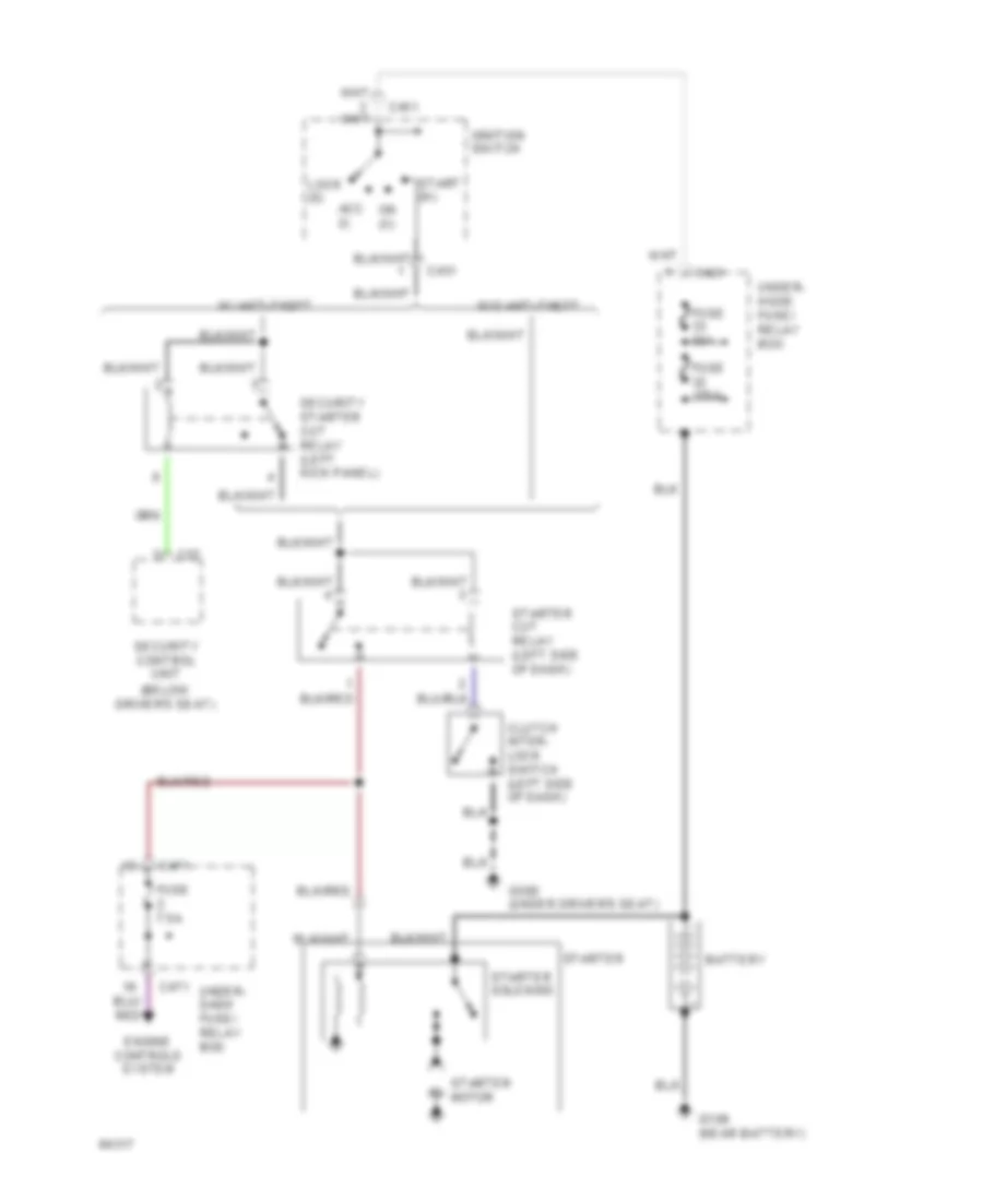
Starting Wiring Diagram, A/T for Honda Prelude 4WS 1994
List of elements for Starting Wiring Diagram, A/T for Honda Prelude 4WS 1994:
- (below center
- (left kick panel)
- A/t gear position switch
- Acc (i)
- Battery
- C421
- C451
- C471
- C57
- Console)
- Engine controls system
- Fuse 100a
- Fuse 50a
- Fuse 7.5a
- G109 (near battery)
- Ignition switch
- Lock (0)
- On (ii)
- Security control unit
- Security starter cut relay (left side of dash)
- Start (iii)
- Starter
- Starter motor
- Starter solenoid
- Under- dash fuse/ relay box
- Under- hood fuse/ relay box
- W/ anti-theft
- W/o anti-theft
Starting Wiring Diagram, M/T for Honda Prelude 4WS 1994
List of elements for Starting Wiring Diagram, M/T for Honda Prelude 4WS 1994:
- (below driver's seat)
- Acc (i)
- Battery
- C421
- C451
- C471
- C57
- Clutch inter- lock switch (left side of dash)
- Engine controls system
- Fuse 100a
- Fuse 50a
- Fuse 7.5a
- G109 (near battery)
- G300 (under driver's seat)
- Ignition switch
- Lock (0)
- On (ii)
- Security control unit
- Security starter cut relay (left kick panel)
- Start (iii)
- Starter
- Starter cut relay (left side of dash)
- Starter motor
- Starter solenoid
- Under- dash fuse/ relay box
- Under- hood fuse/ relay box
- W/ anti-theft
- W/o anti-theft
SUPPLEMENTAL RESTRAINTS
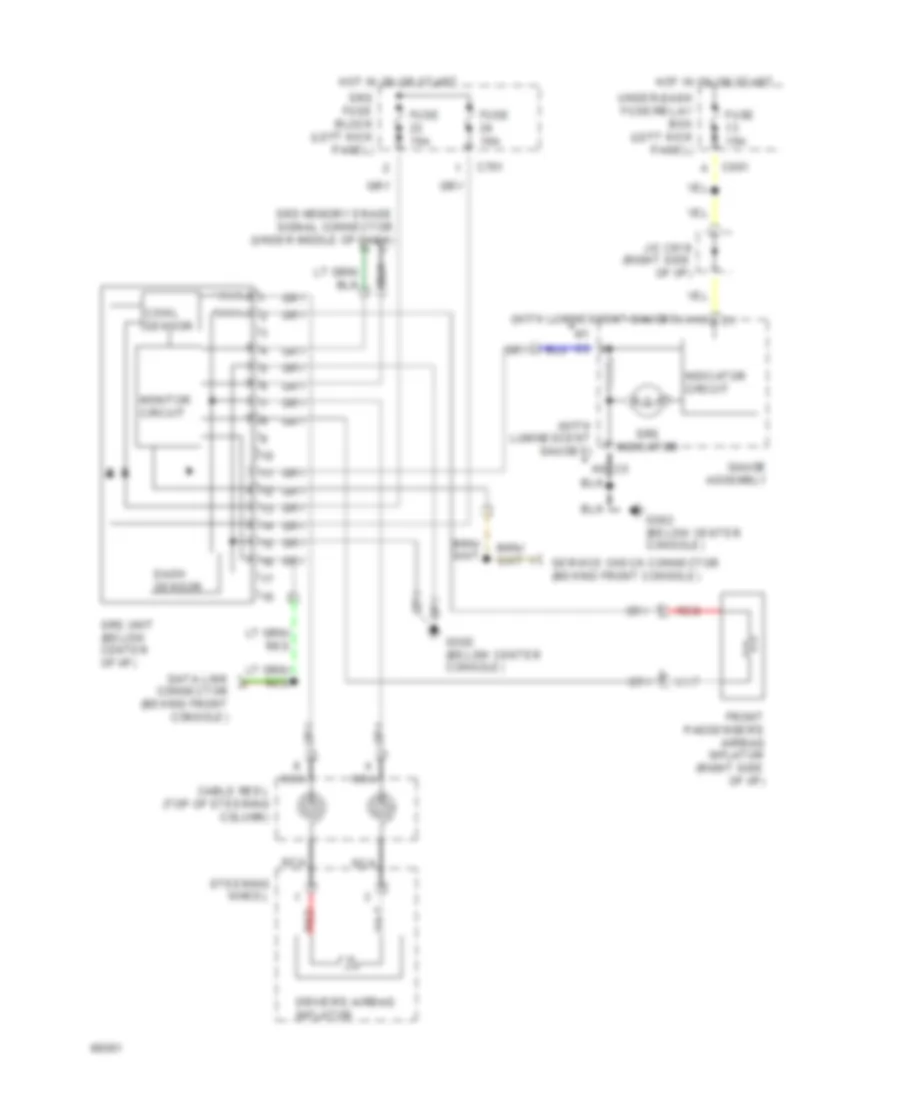
Supplemental Restraint Wiring Diagram for Honda Prelude 4WS 1994
List of elements for Supplemental Restraint Wiring Diagram for Honda Prelude 4WS 1994:
- (with luminescent gauges)
- C601
- C701
- Cable reel (top of steering column)
- Cowl sensor
- Dash sensor
- Data link connector (behind front console)
- Driver's airbag inflator
- Front passenger's airbag inflator (right side of i/p)
- Fuse 10a
- Fuse 15a
- G302 (below center console)
- Gauge assembly
- H10
- Hot in on or start
- Indicator circuit
- J/c c619 (right side of i/p)
- Monitor circuit
- Nca
- Red
- Service check connector (behind front console)
- Srs fuse block (left kick panel)
- Srs indicator
- Srs memory erase signal connector (under middle of dash)
- Srs unit (below center of i/p)
- Steering wheel
- Under-dash fuse/relay box (left kick panel)
TRANSMISSION
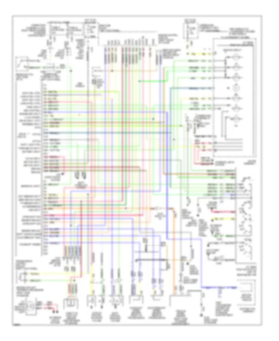
Transmission Wiring Diagram for Honda Prelude 4WS 1994
List of elements for Transmission Wiring Diagram for Honda Prelude 4WS 1994:
- (1993 s, si & sr models) (right kick panel)
- (left kick panel)
- (or red)
- +5v reference
- 1994 models w/o luminescent gauges & 1993 models
- A/c on input
- A/t gear position console light
- A/t gear position indicator
- A/t gear position switch (left of gear selector)
- A10
- A11
- A12
- A13
- A14
- A15
- A16
- A17
- A18
- A19
- A20
- A21
- A22
- A23
- A24
- A25
- A26
- Afsa
- Afsb
- Air conditioning system
- Anti-theft system
- Atp d3
- Atp d4
- Atp pn
- Atp1
- Atp2
- Battery input
- Brake sw input
- Brake switch (left side of i/p)
- C131 (right rear eng compt)
- C419 (right of i/p)
- C419 (right side i/p)
- C419 (right side of i/p)
- C422
- C424
- C445
- C446
- C447 (behind left side of i/p)
- C460 (left side of i/p)
- C469
- C471
- C601
- C908
- Countershaft spd
- Countershaft speed sensor (rear of transmission)
- Cruise control system
- D10
- D11
- D12
- D13
- D14
- D15
- D16
- D17
- D18
- D19
- D20
- D21
- D22
- Dimming circuit
- Distributor assembly
- Drive input
- Drive inputs
- Ect
- Ect sensor input
- Engine control module (right front of floor)
- Engine coolant temperature sensor (right side
- Engine spd input
- Exterior lights system
- Fas
- Fuse 10a
- Fuse 15a
- Fuse 41 stop/horn 15a
- Fuse 43 clock/rad 7.5a
- G120 (right side of engine)
- G203 g201 (behind right i/p)
- G302 (behind front console)
- Gauge assembly
- Ground
- Hot at all times
- Hot in on or start
- Ignition control module
- Ignition input
- Illum cancel
- Indic control
- Interior lights system
- Lock-up control solenoid valves
- Lockup sol ctrl
- Mainshaft speed
- Mainshaft speed sensor (front of transmission)
- Models
- Nca
- Of engine)
- Park input
- Park/neutr input
- Pnk
- Red
- Reverse input
- Scs
- Sensor ground
- Service check connector (behind front console)
- Service chk conn
- Sg1
- Sg2
- Shift acknowledge
- Shift control solenoid valves
- Shift interlock system
- Shift lock ctrl
- Shift sol ctrl
- Srs fuse block (left kick panel)
- T10
- Test tachometer connector (right side of engine compartment)
- Throttle position sensor (center rear of engine)
- Tp sensor input
- Tps
- Transmission control module (right kick panel)
- Under- dash fuse/ relay box
- Under-dash fuse/relay box
- Under-dash fuse/relay box (left kick panel)
- Under-dash fuse/relay box (left kick panel) c601
- Under-hood fuse/relay box (right rear corner of engine compartment)
- Up/dn shift sig
- Vcc1
- Vcc2
- Vehicle speed sensor (right side of engine compartment)
- Vref
- Vss input
- W luminescent gauges
WARNING SYSTEMS
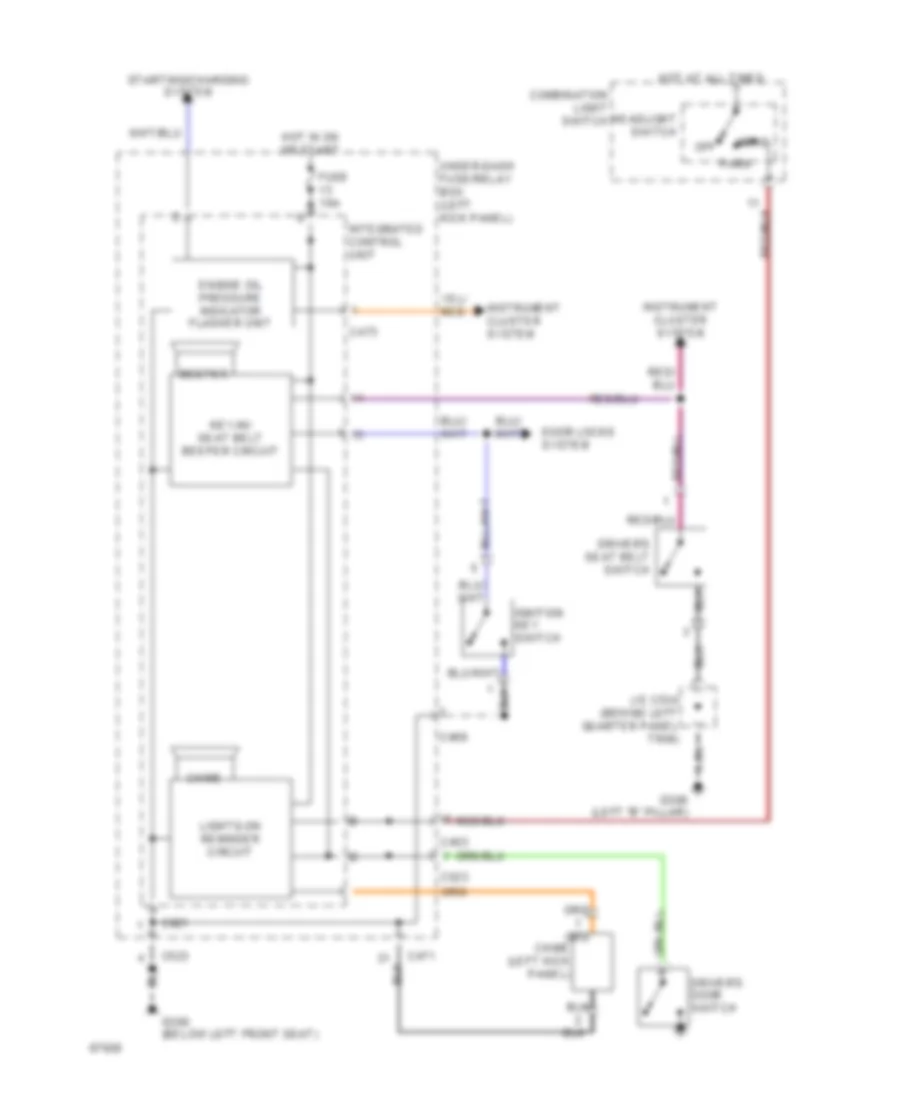
Warning System Wiring Diagrams for Honda Prelude 4WS 1994
List of elements for Warning System Wiring Diagrams for Honda Prelude 4WS 1994:
- Beeper
- C403
- C469
- C471
- C473
- C523
- C921
- Chime
- Chime (left kick panel)
- Combination light switch
- Door locks system
- Driver's door switch
- Driver's seat belt switch
- Engine oil pressure indicator flasher unit
- Fuse 10a
- G300 (below left front seat)
- G308 (left "b" pillar)
- Head
- Headlight switch
- Hot at all times
- Hot in on or start
- Ignition key switch
- Instrument cluster system
- Integrated control unit
- J/c c534 (behind left quarter panel trim)
- Key-in/ seat belt beeper circuit
- Lights-on reminder circuit
- Nca
- Off
- Park
- Starting/charging system
- Under-dash fuse/relay box (left kick panel)
WIPER/WASHER
Wiper/Washer Wiring Diagram for Honda Prelude 4WS 1994
List of elements for Wiper/Washer Wiring Diagram for Honda Prelude 4WS 1994:
- (not used)
- B10
- B11
- C468
- C471
- C472
- C523
- C909
- Fuse 17 30a
- G100 (left front fender)
- G300 (below left front seat)
- Ground
- Hot in on or start
- Int
- Int wipe input
- Integrated control unit
- Intermittent wiper circuit
- J/c c326 (above left kick panel)
- Mist
- Off
- Park
- Park input
- Run
- Under-dash fuse/relay box (left kick panel)
- Wash
- Washer on input
- Wind- shield wiper/ washer switch
- Windshield washer motor (behind lower left front bumper fascia)
- Windshield wiper intermittent relay (left rear corner of engine compartment)
- Windshield wiper motor (behind left side of air scoop)
- Wipe int ctrl

 Čeština
 Dansk
Dansk Deutsch
 Ελληνικά
 English
 English
 Español
 Suomi
Suomi Français
 Français
 עברית
עברית Hrvatski
 Magyar
 日本語
日本語 한국어
한국어 Nederlands
 Polski
 Português
 Português
 Română
 Русский
 Slovenčina
 Slovenščina
 Svenska
 Türkçe
 中文 (中国)