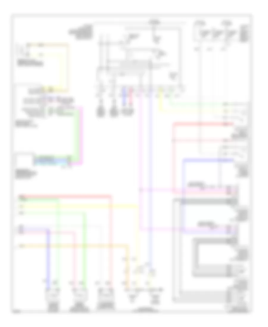
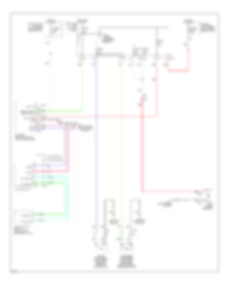
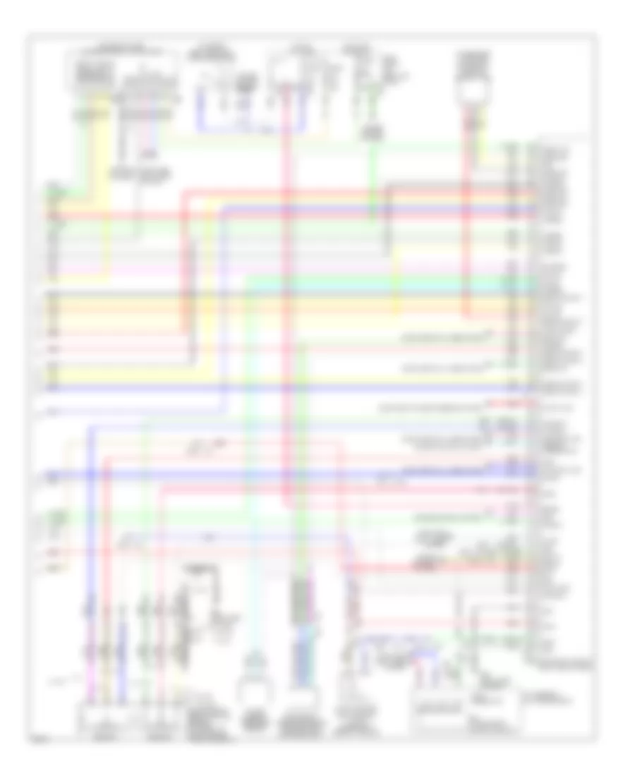
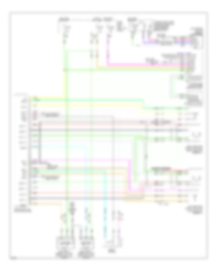
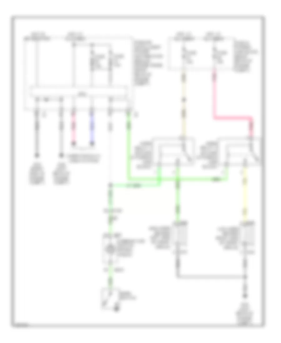
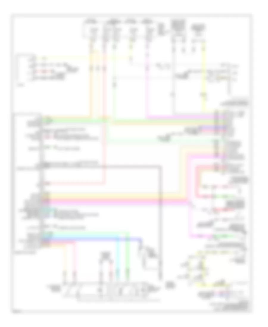
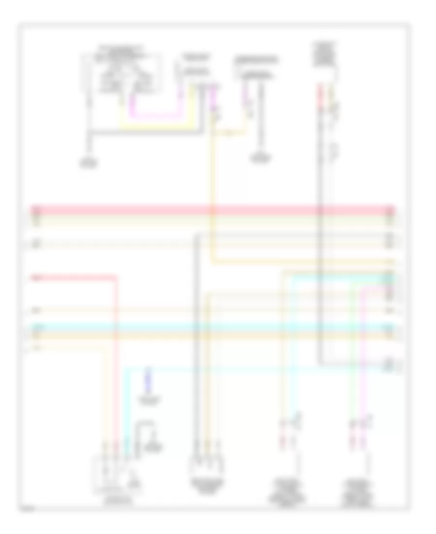
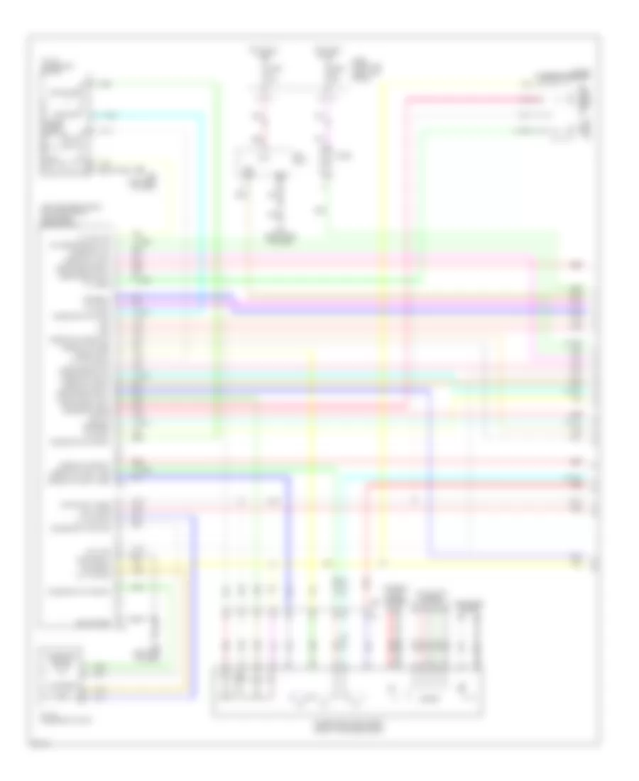
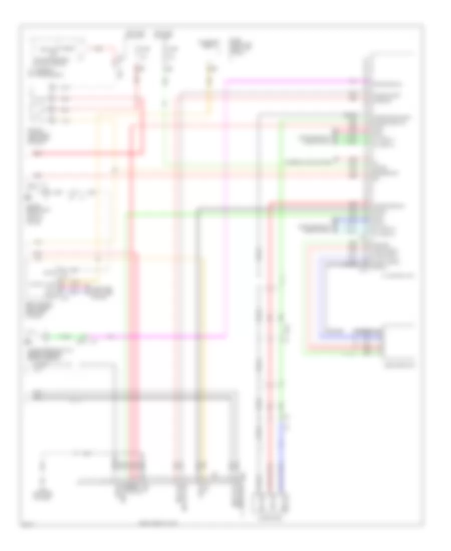
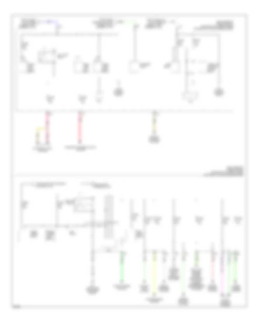
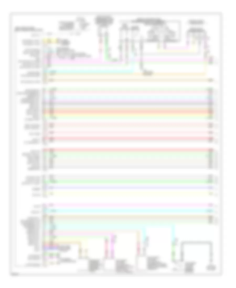
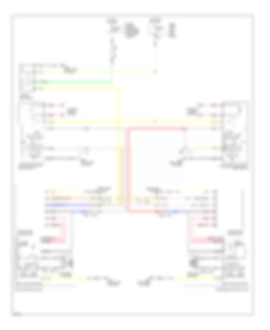
AIR CONDITIONING
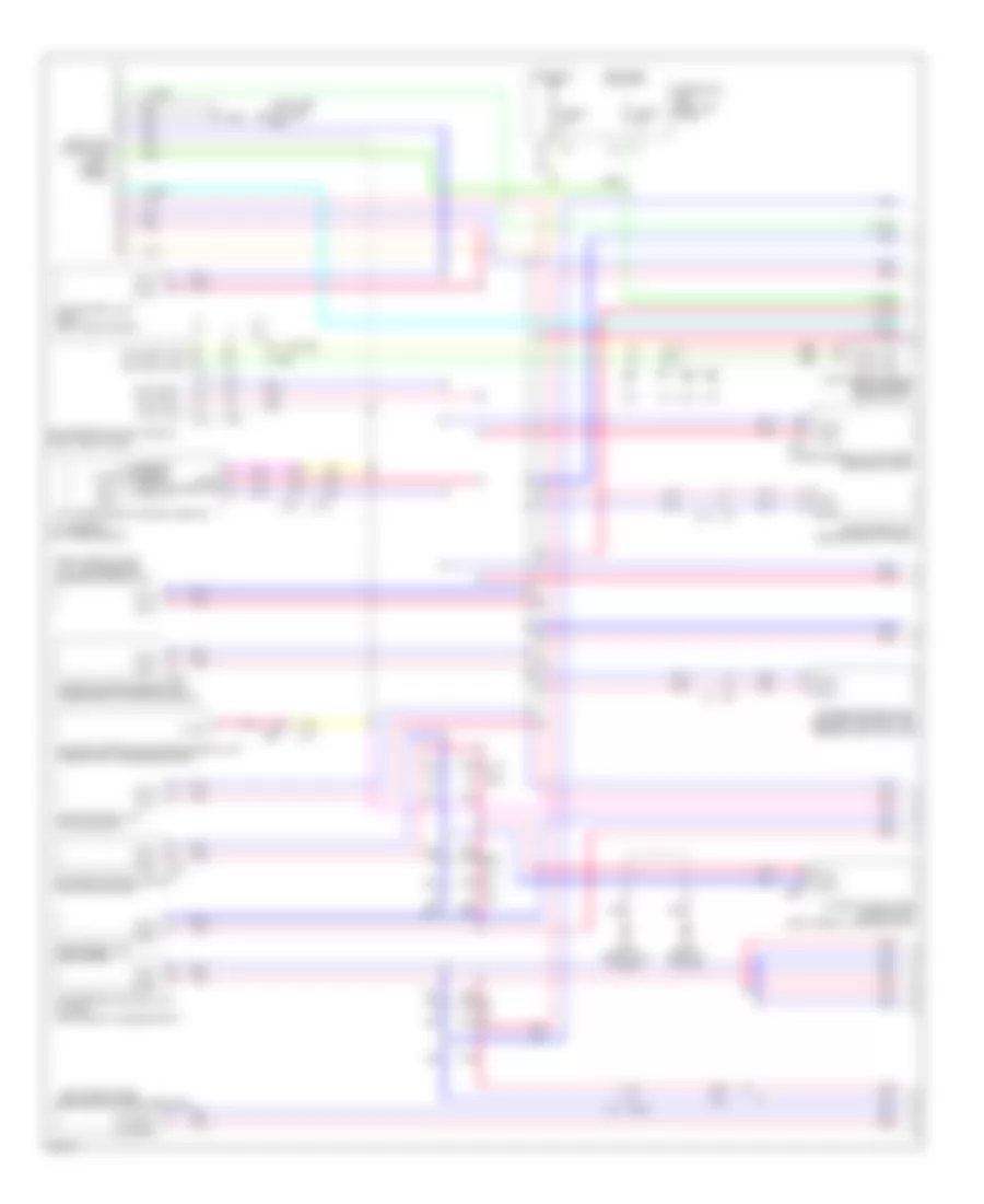
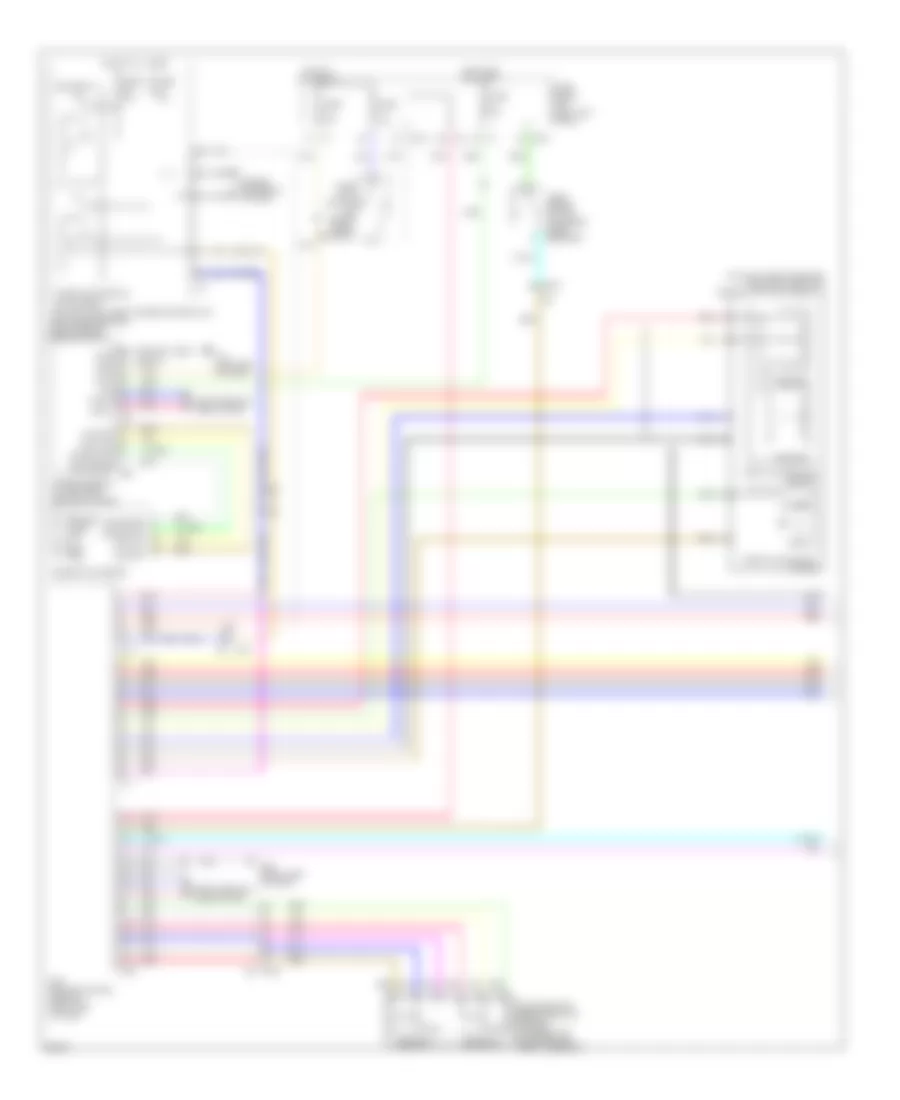
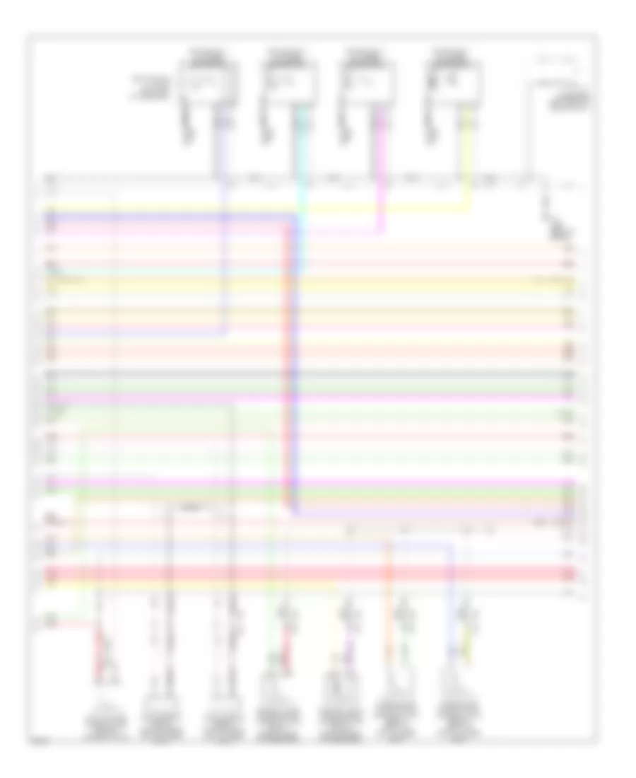
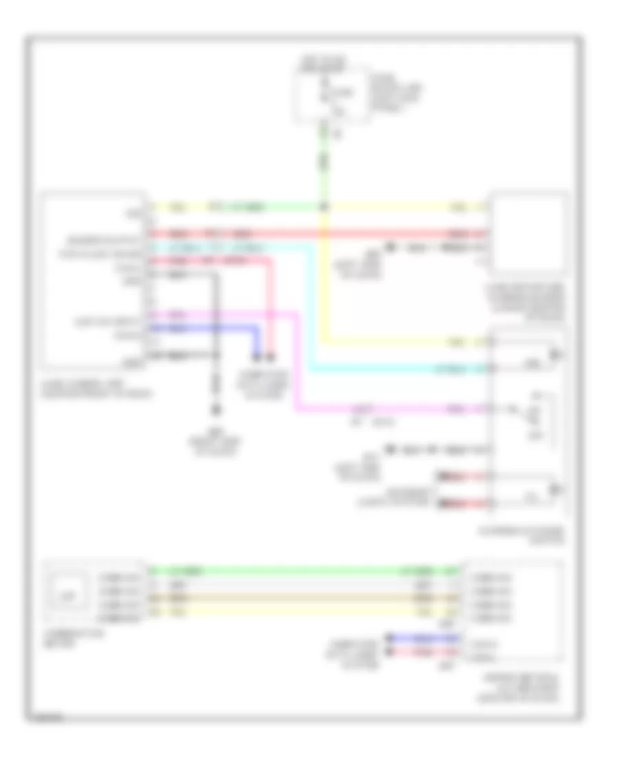
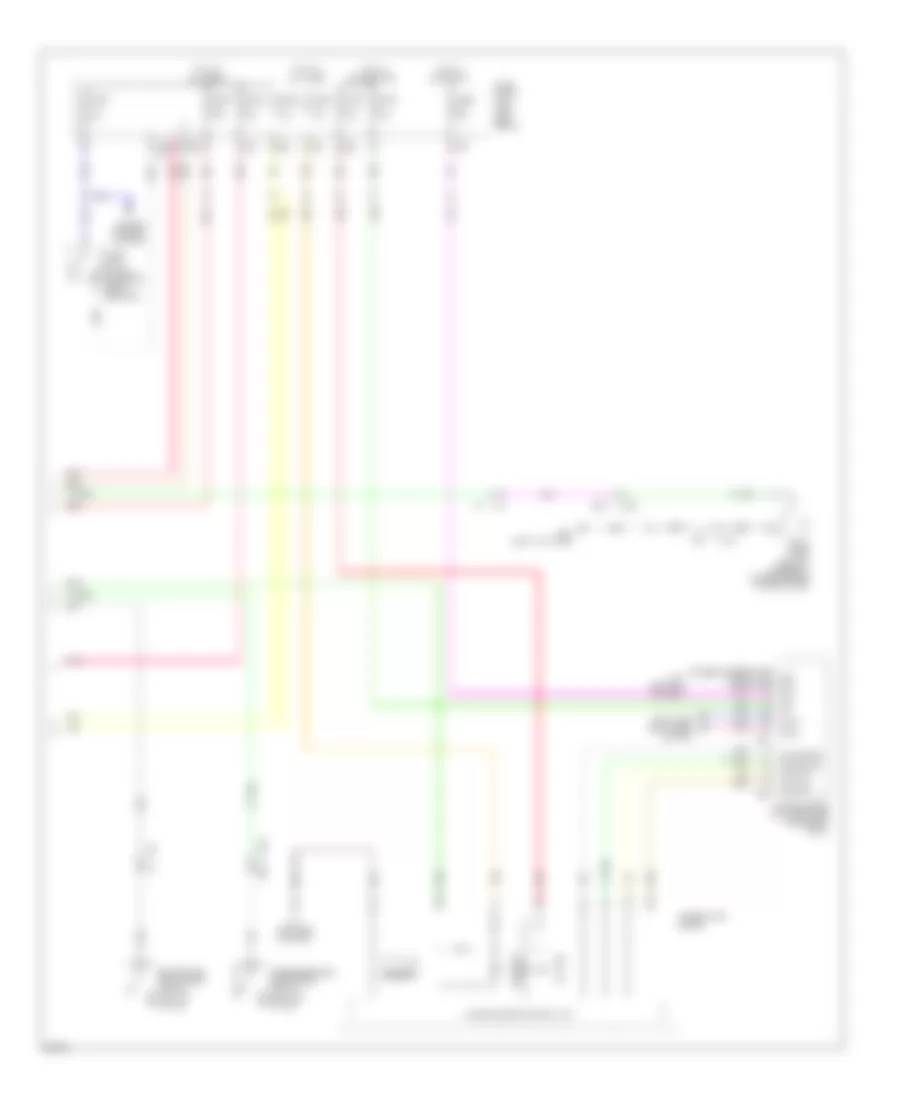
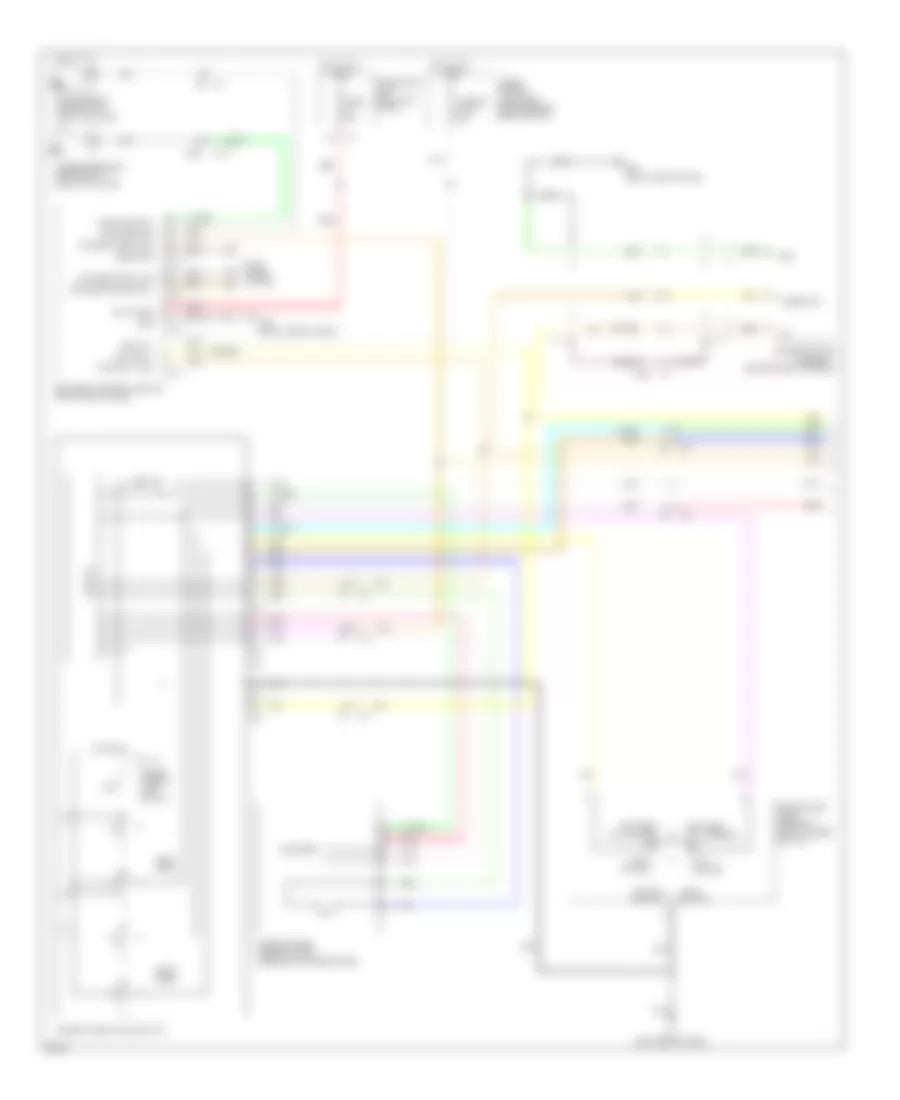
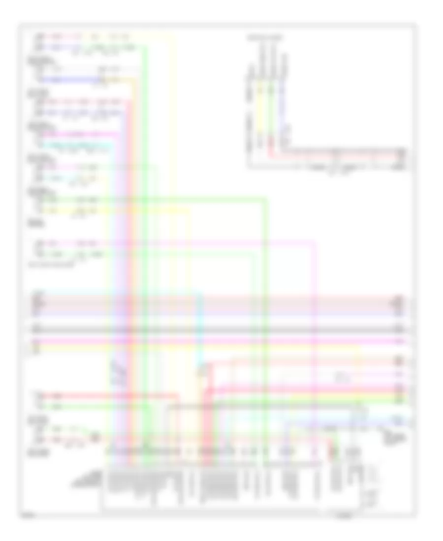
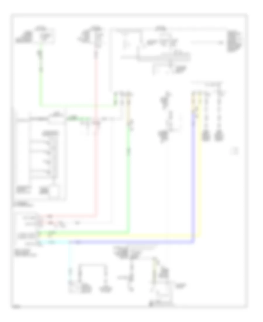
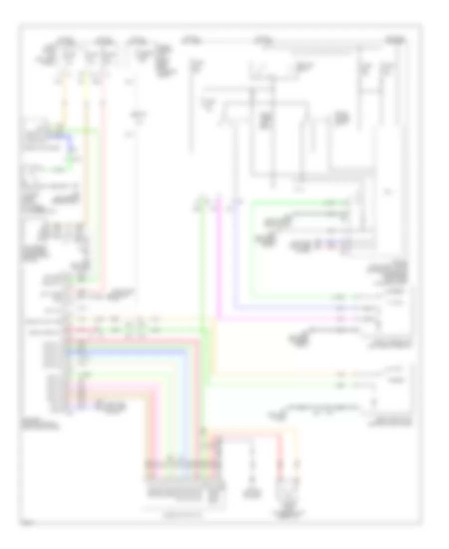
Automatic A/C Wiring Diagram (1 of 2) for Infiniti FX50 2013
 https://portal-diagnostov.com/license.html
Automotive Electricians Portal FZCO
Automotive Electricians Portal FZCO
https://portal-diagnostov.com/license.html
https://portal-diagnostov.com/license.html
Automotive Electricians Portal FZCO
Automotive Electricians Portal FZCO
List of elements for Automatic A/C Wiring Diagram (1 of 2) for Infiniti FX50 2013:
- (pin no:48 to 52 not used)
- (right end of dash)
- 100a
- Acc
- Amb gnd
- Amb sens
- Amp-lcd
- Amp-meter
- Amplifier
- Aqs power
- Aqs s gnd
- Aqs s output
- Bat
- Bcm (body control module)
- Blower motor (lower right side of dash)
- Blower relay
- Blower rly cont
- Brk fluid sw
- Can-h
- Can-l
- Computer data lines system
- E101
- E103
- E106
- E106 m6
- Ecv sig
- Engine controls system
- Exhaust gas/ outside odor detecting sensor (behind center of front grille)
- Fuel lvl gnd
- Fuel lvl sens
- Fuse 10a
- Fuse 15a
- Fuse block (j/b) (left kick panel)
- Fusible link e
- Fusible link holder (right rear of engine compt)
- Gas sens
- Gnd
- Hot at all times
- Hot in on or acc
- Hot in on or start
- Ign
- In veh gnd
- In veh sens
- Instrument cluster system
- Intake door motor (right side of hvac unit)
- Intake gnd
- Intake sens
- Ion mode
- Ion on off
- Ion sens
- Ionizer (left side of dash)
- Lan sig
- Lcd-amp
- Left air mix door motor (left side of dash)
- M11 (left end of dash)
- M122
- M251 m91
- M66
- M67
- Man mode sw
- Meter-amp
- Mode door motor (left side of hvac unit)
- Mtr ctrl sig
- Mtr pwr sply
- Non-man
- Paddle down
- Paddle up
- Pnk
- Power tops system
- Prk brk sw
- Red
- Right air mix door motor (left side of hvac unit)
- Seat belt buckle sw
- Shift dwn sw
- Shift up sw
- Spd (8-pulse)
- Sun gnd
- Sun sens
- Sunload sensor (top left side of dash)
- Sw sig
- Tan
- Transmissions system
- Unified meter & a/c amplifier (center of dash)
- Veh spd (2-pulse)
- Warning systems
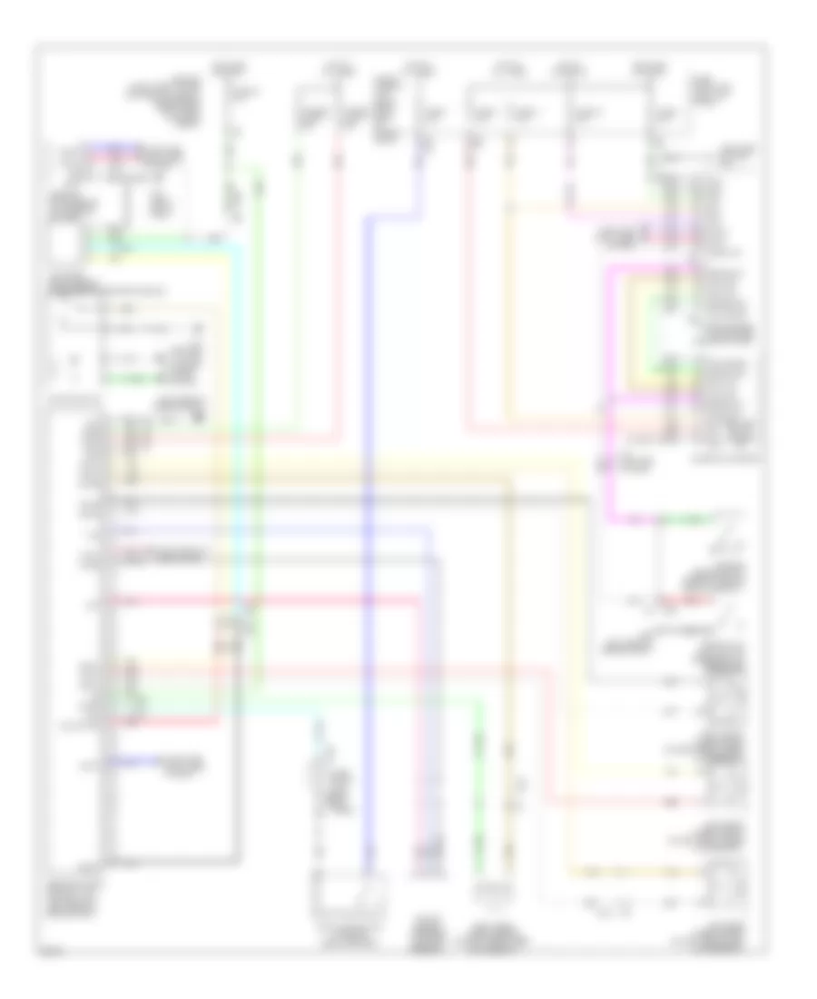
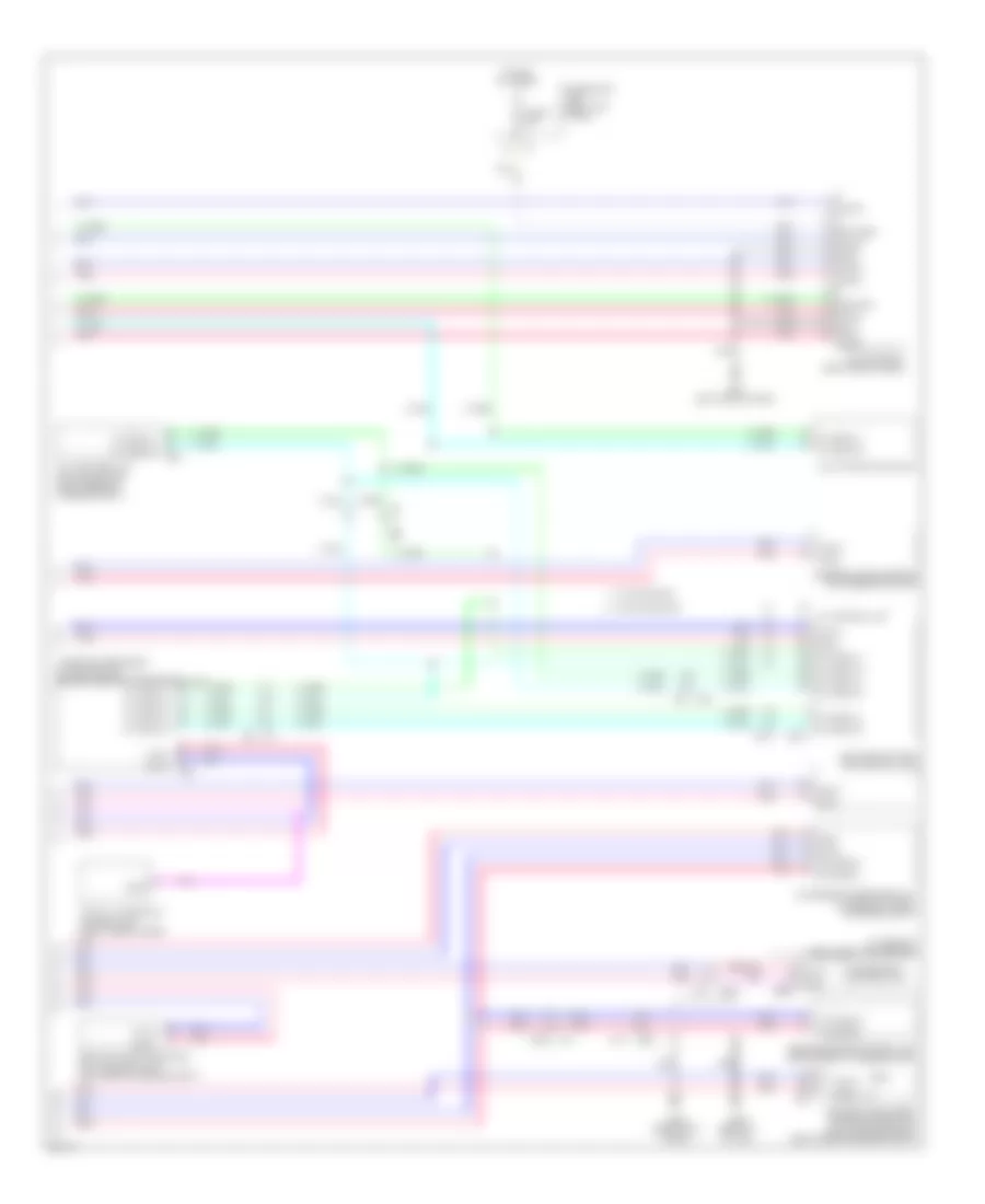
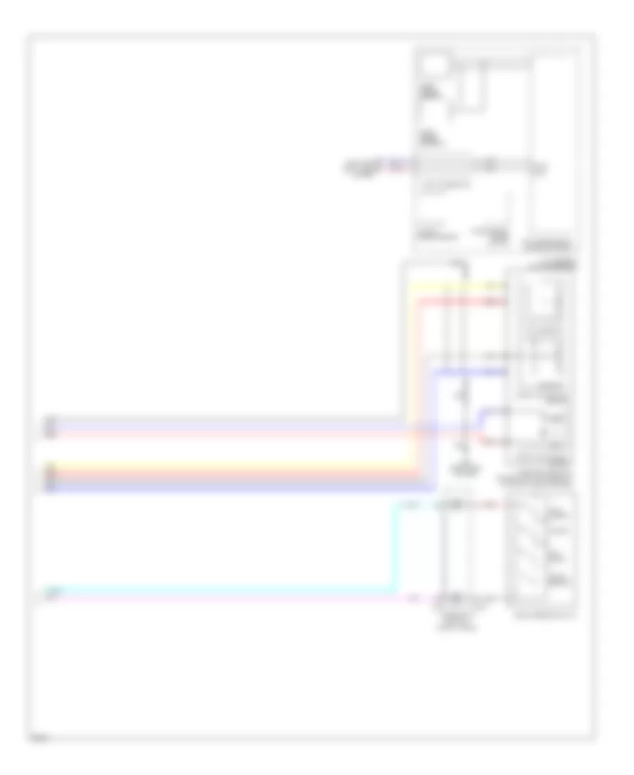
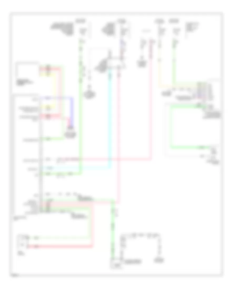
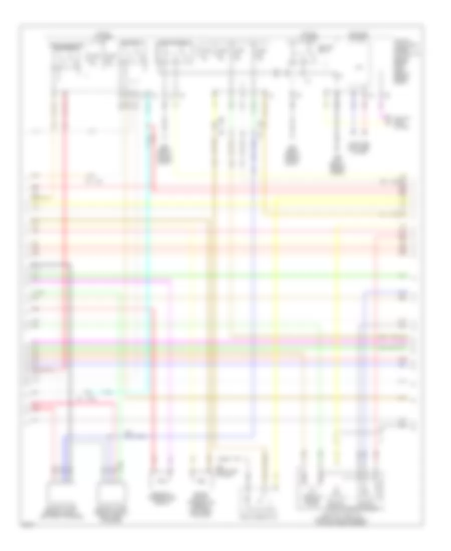
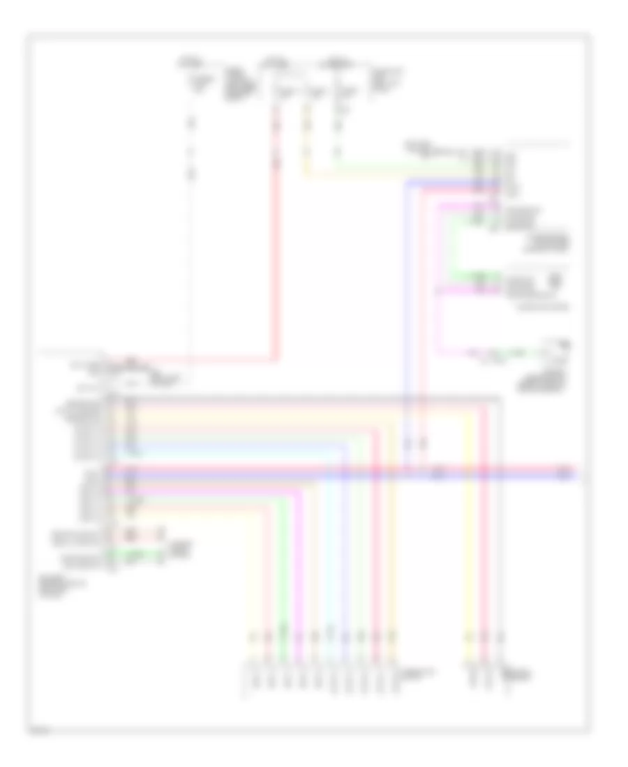
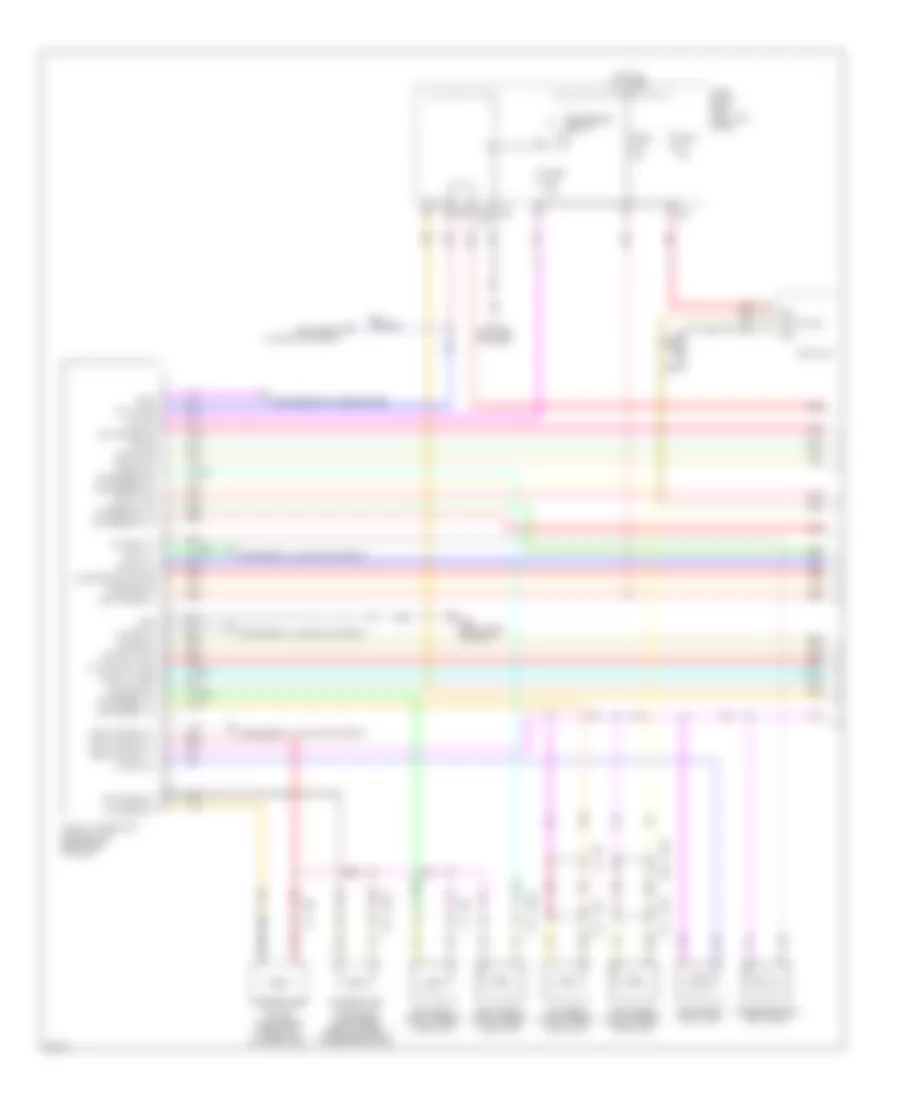
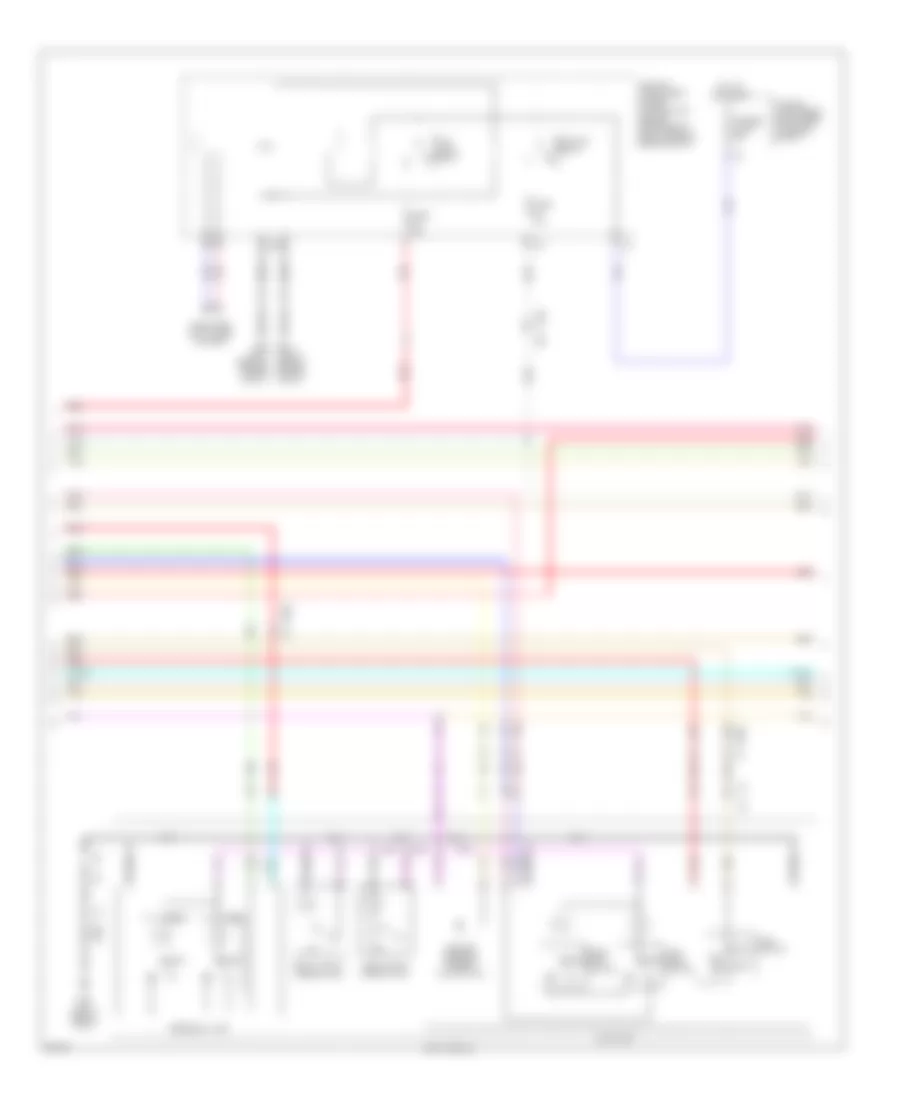
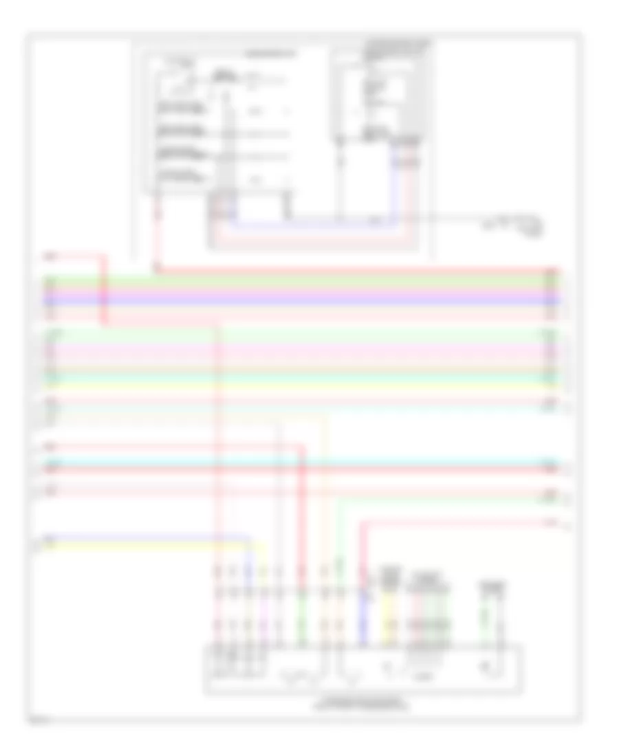
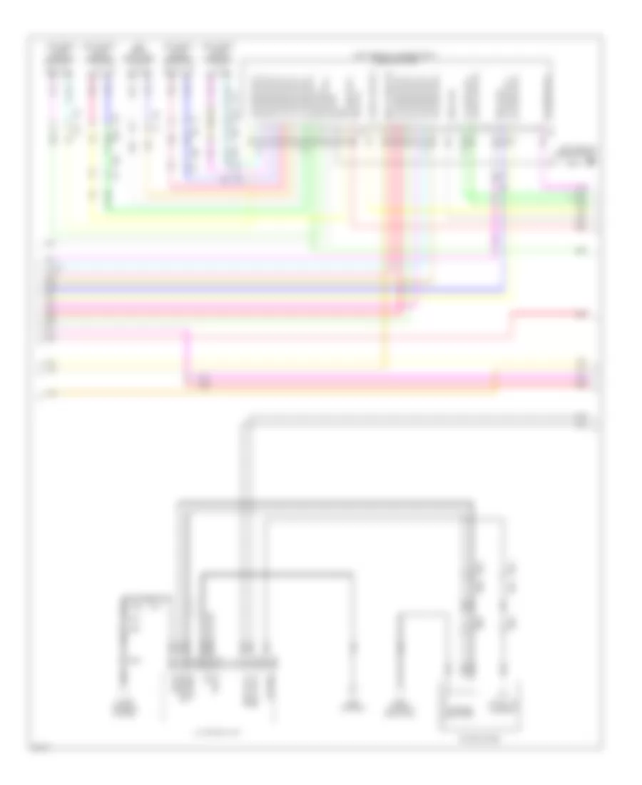
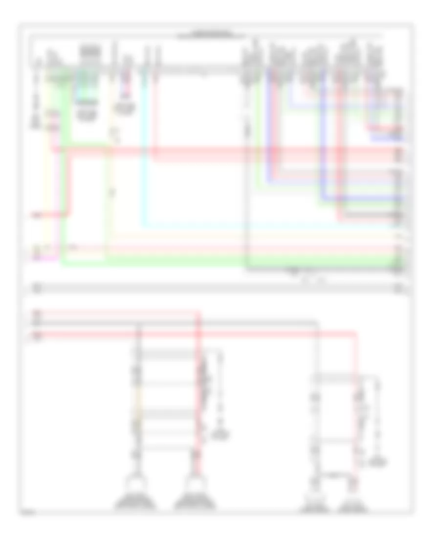
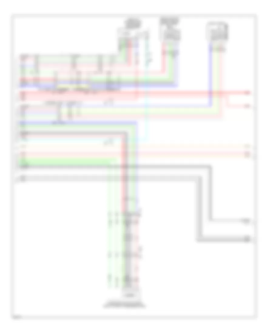
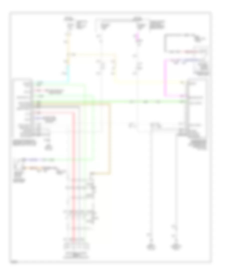
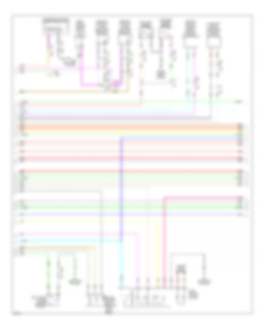
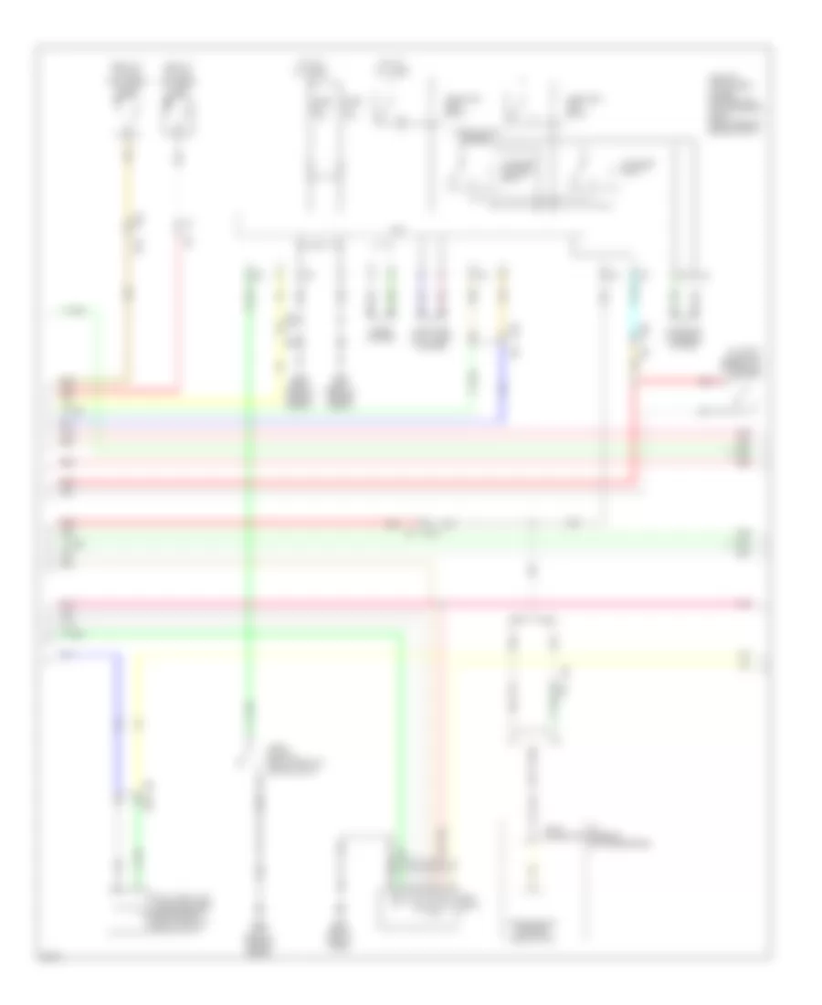
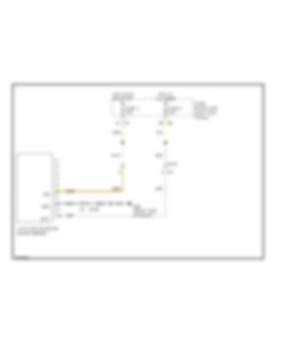
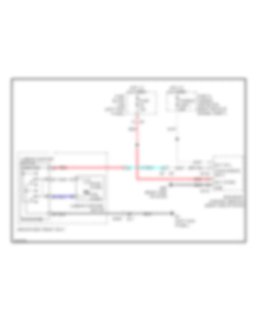
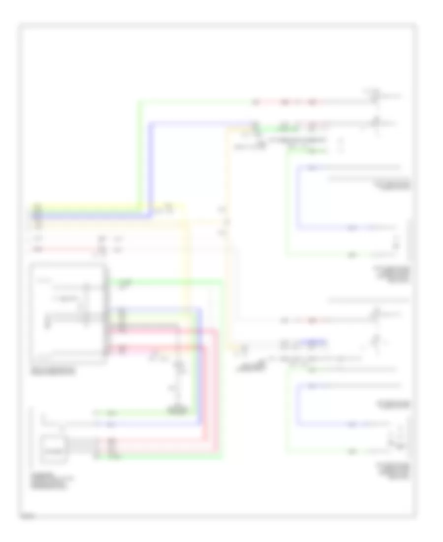
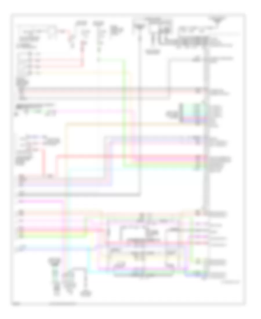
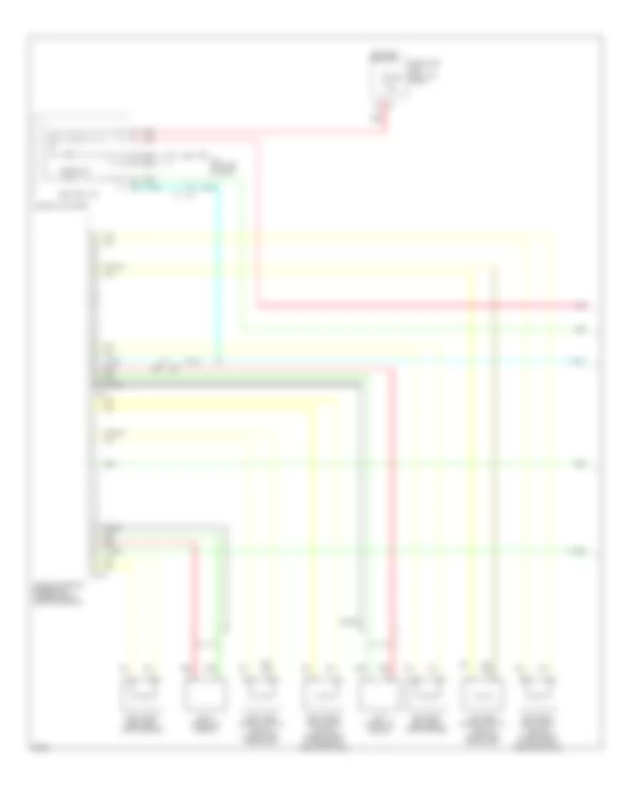
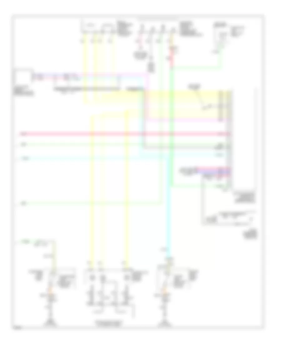
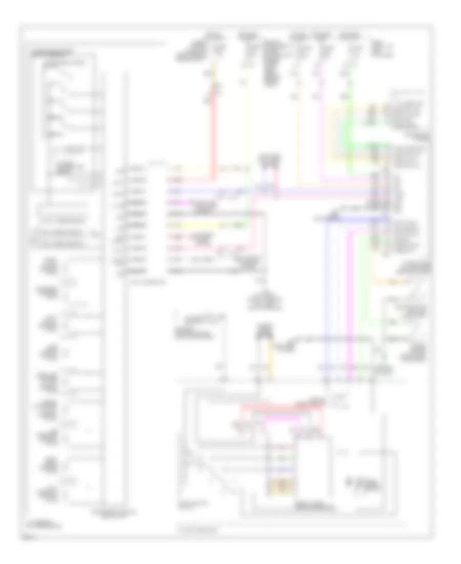
Automatic A/C Wiring Diagram (2 of 2) for Infiniti FX50 2013
List of elements for Automatic A/C Wiring Diagram (2 of 2) for Infiniti FX50 2013:
- (left rear of engine compt) e46
- (right side of engine compt) e22
- A/c relay
- Ambient sensor (behind center of front grille)
- Can comm line
- Compressor (left front of engine)
- Computer data lines system
- Cooling fan control module 1 (on cooling fan 1 assembly)
- Cooling fan control module 2 (on cooling fan 2 assembly)
- Cooling fan motor 1 (behind right side of radiator)
- Cooling fan motor 2 (behind left side of radiator)
- Cooling fan relay 1 (right rear of engine compt)
- Cooling fan relay 2 (in fuse & fusible link block)
- Cpu
- E10
- E10 f10
- E22 (right side of engine compt)
- E301
- E303
- E37
- E38
- E46 (left rear of engine compt)
- Ect snsr
- Ecv
- Engine control module (ecm) (right end of dash)
- Engine coolant temperature sensor (right rear of engine)
- F10
- F103
- F110
- F111
- F43
- F44
- Fuse 10a
- Fusible link d 80a
- Fusible link holder (right rear of engine compt)
- Fusible link o 50a
- Fusible link s 50a
- Hot at all times
- Ignition relay
- In-vehicle sensor (left side of dash)
- Intake sensor (lower right center of dash)
- Ipdm e/r (intelligent power distribution module engine room) (right rear of engine compt)
- M116
- M160
- Magnet clutch
- Nca
- Pnk
- Press snsr
- Red
- Refrigerant pressure sensor (center front of engine compt)
- Snsr gnd
- Snsr pwr sply
- Tan
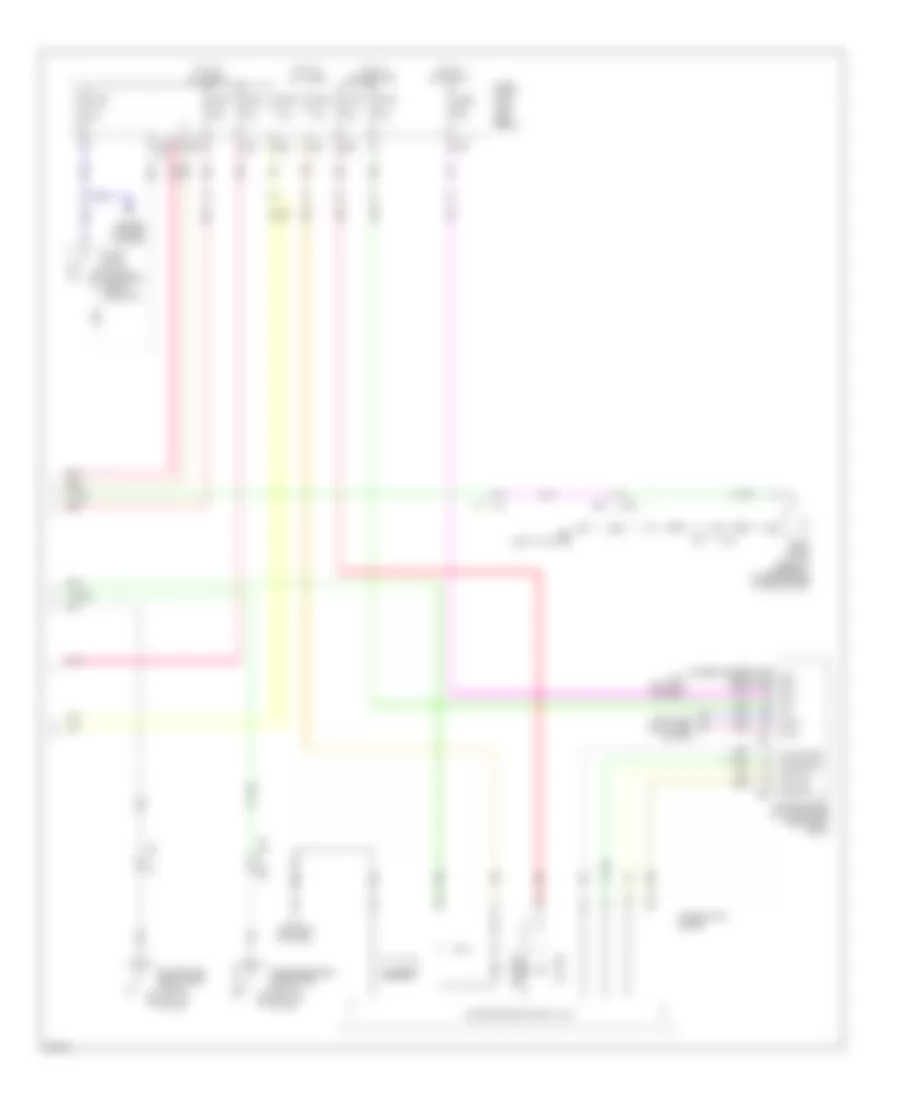
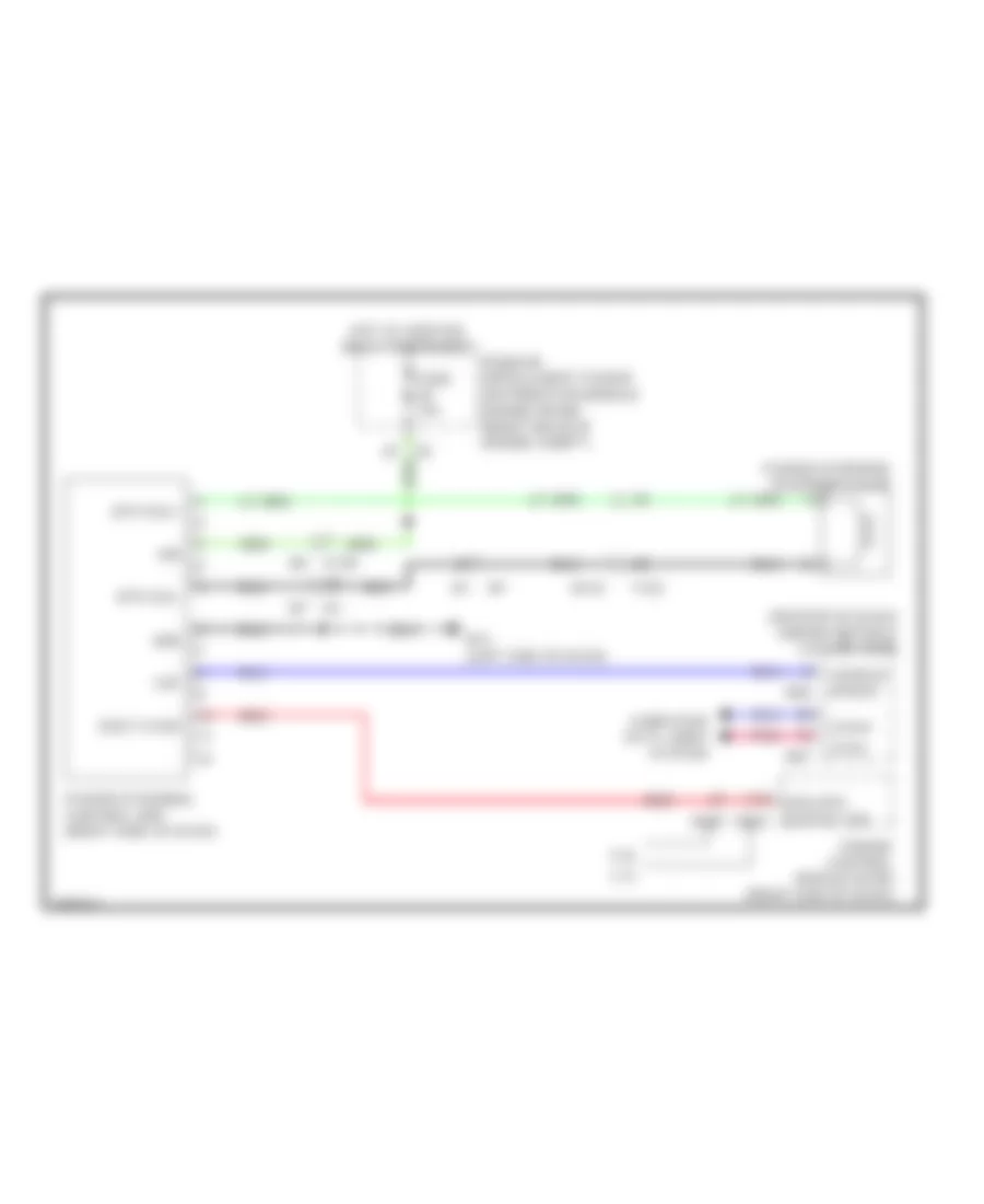
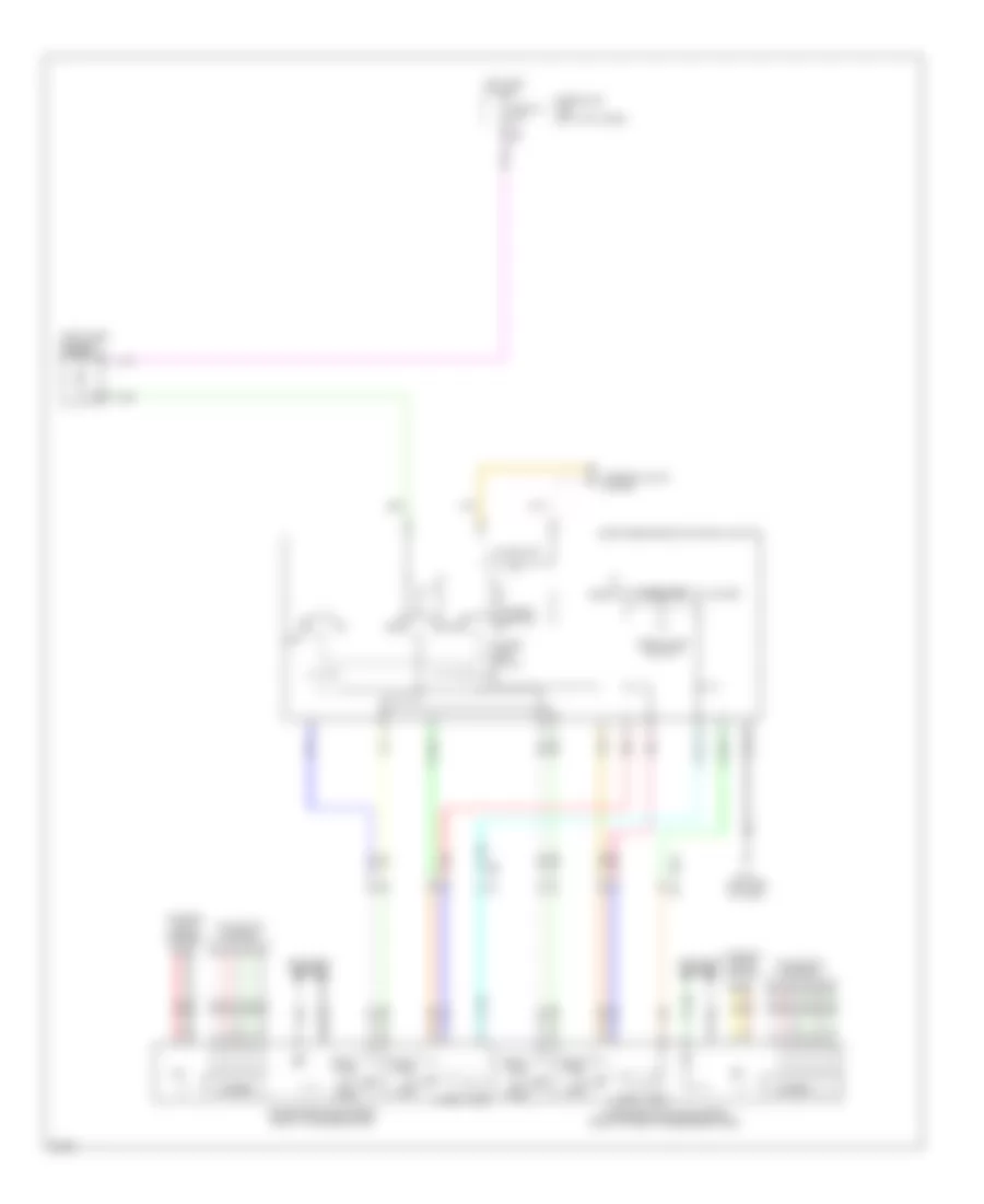
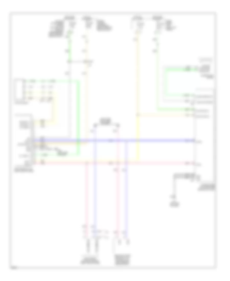
ANTI-LOCK BRAKES
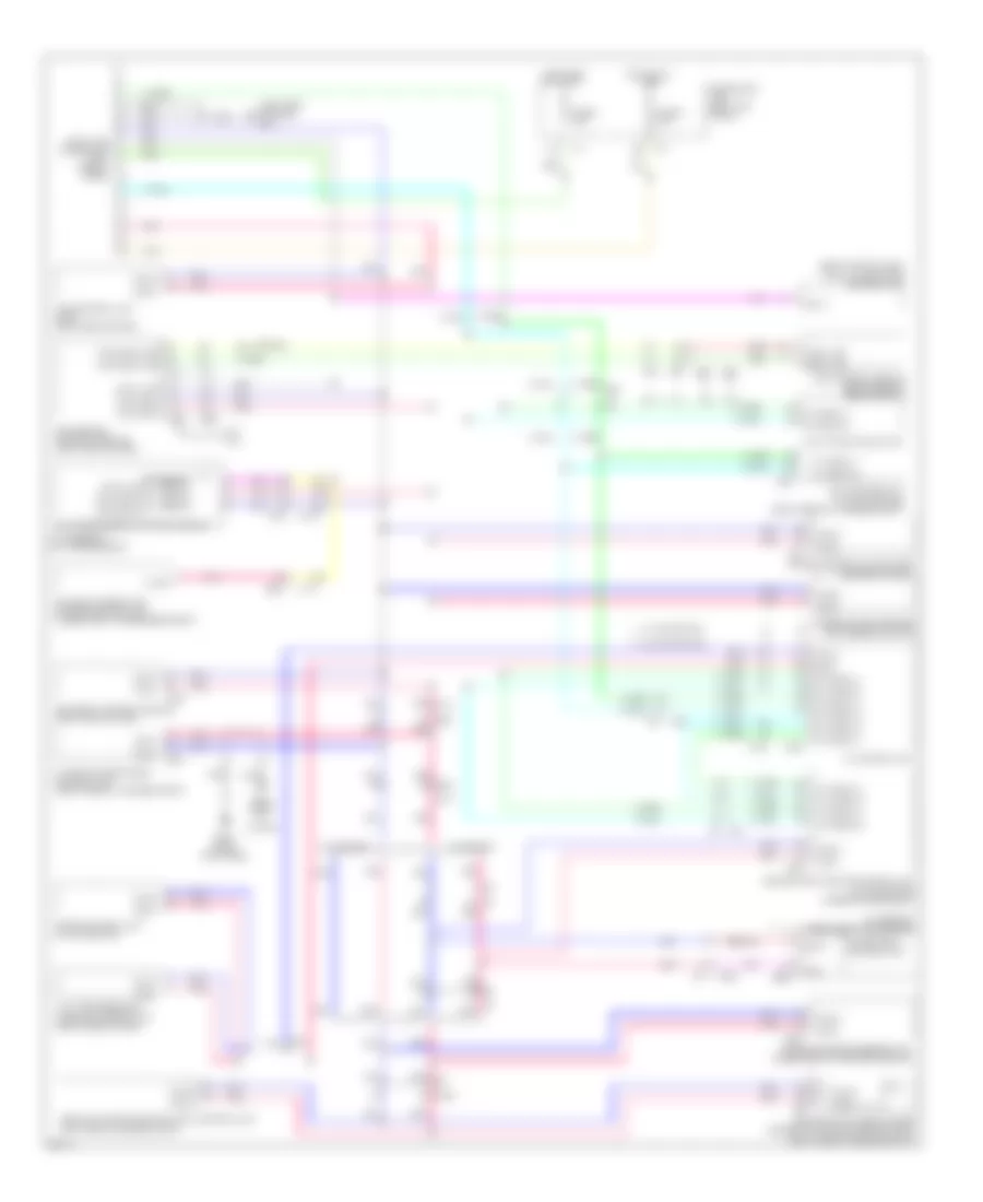
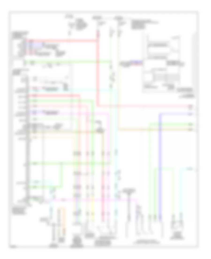
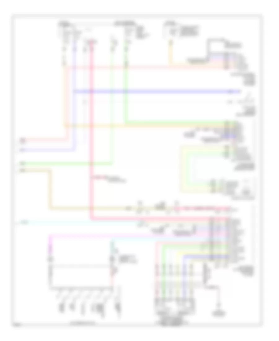
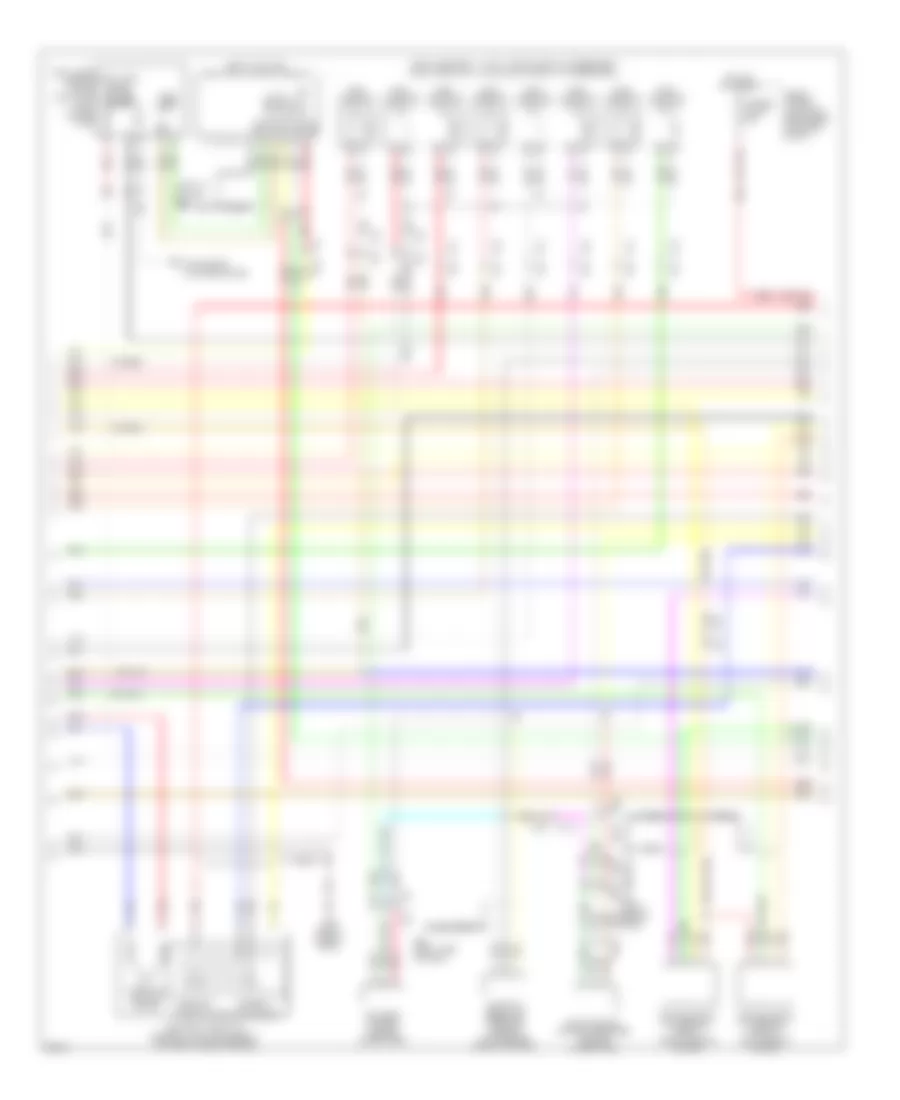
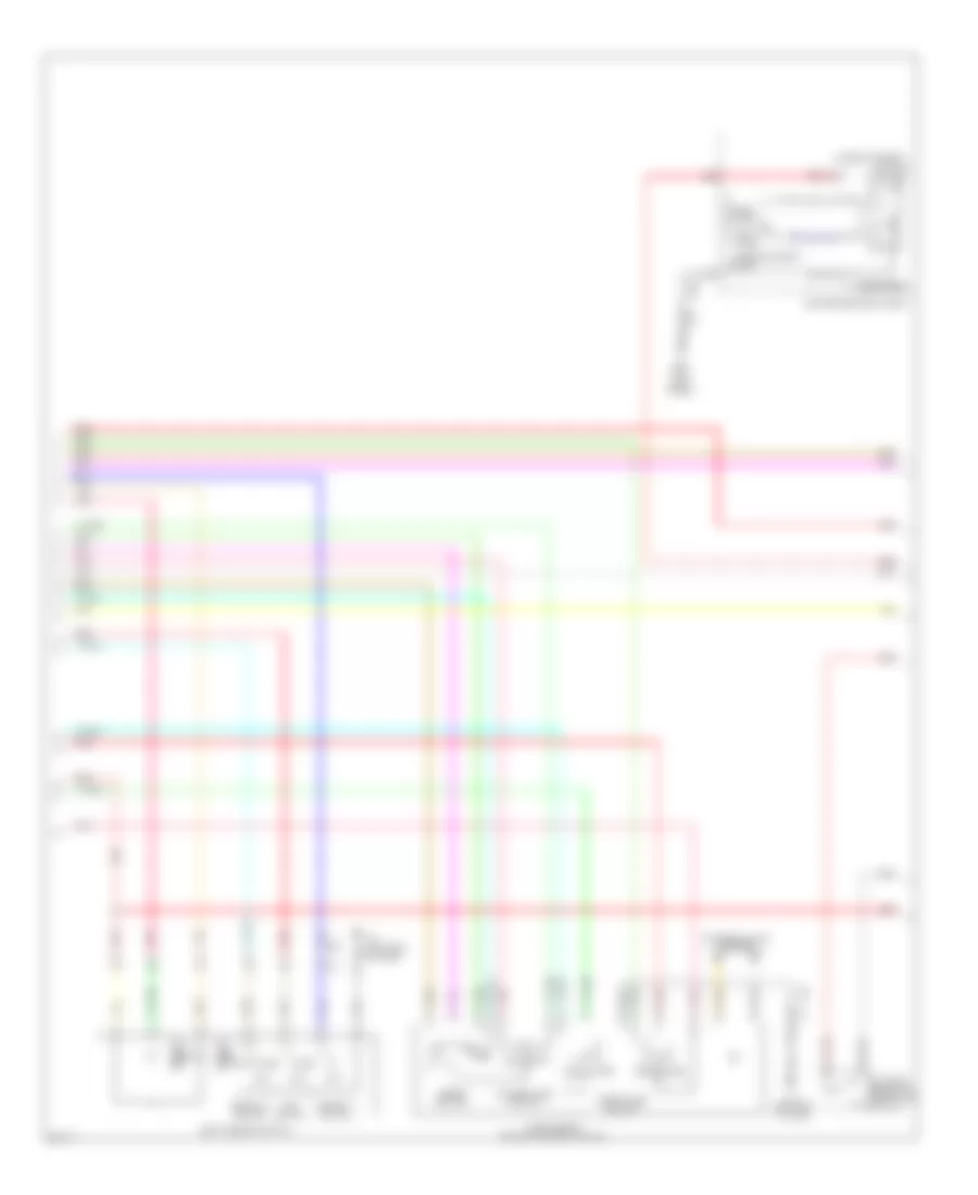
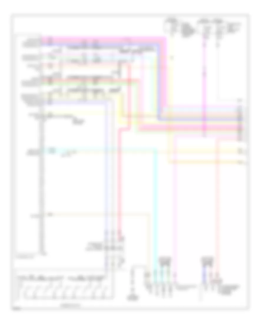
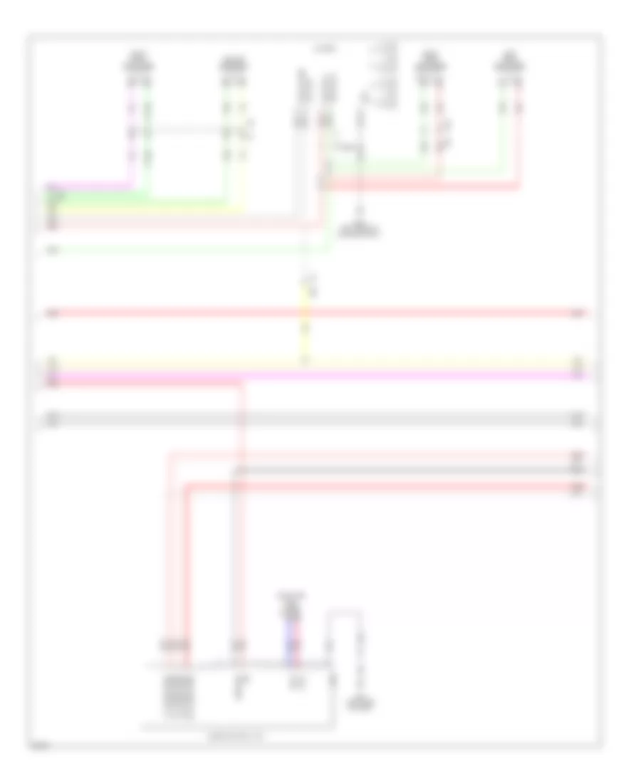
Anti-lock Brakes Wiring Diagram for Infiniti FX50 2013
List of elements for Anti-lock Brakes Wiring Diagram for Infiniti FX50 2013:
- (left rear of engine compt) e43
- (left side of dash) m55
- (on steering column)
- 12c
- A gnd
- Abs actuator & electric unit (control unit) (left rear of engine compt)
- Abs, vdc, vdc off & brake ind
- Acc
- Amp lcd
- Amp meter
- Bat
- Bls
- Brake fluid level switch (in brake fluid reservoir)
- Brake sw
- Bus-h
- Bus-l
- Can-h
- Can-l
- Combination meter
- Computer data lines system
- Dp fl
- Dp fr
- Dp rl
- Dp rr
- Ds fl
- Ds fr
- Ds rl
- Ds rr
- E103
- E104
- E106
- E106 m6
- E46 (left rear of engine compt)
- Fuse & fusible link block (right rear of engine compt)
- Fuse 11 10a
- Fuse 19 10a
- Fuse 3 10a
- Fuse 4 10a
- Fuse 45 10a
- Fuse 7 10a
- Fuse block (j/b) (left kick panel)
- Fusible link m 30a
- Fusible link n 50a
- Gnd
- Hot at all times
- Hot in acc or on
- Hot in on or start
- Ign
- Ill
- Interior lights system
- Ipdm e/r (intelligent power distribution module engine room) (right rear of engine compt)
- Lcd amp
- Left front wheel sensor (on left front wheel hub assembly)
- Left rear wheel sensor (on left rear wheel hub assembly)
- Level sw
- M11 (left end of dash)
- M66
- M67
- Meter amp
- Parking brake switch (base of parking brake assembly)
- Pnk
- Red
- Right front wheel sensor (on right front wheel hub assembly)
- Right rear wheel sensor (on right rear wheel hub assembly)
- Shield
- Steering angle sensor
- Stop lamp switch (on brake pedal bracket)
- Tan
- Ubmr
- Ubvr
- Unified meter & a/c amplifier (center of dash)
- Ust
- Vac
- Vacuum sensor (on brake booster assembly)
- Vdc off sw
- Vdc off switch
- Yaw rate/ side g sensor (under rear of center console)
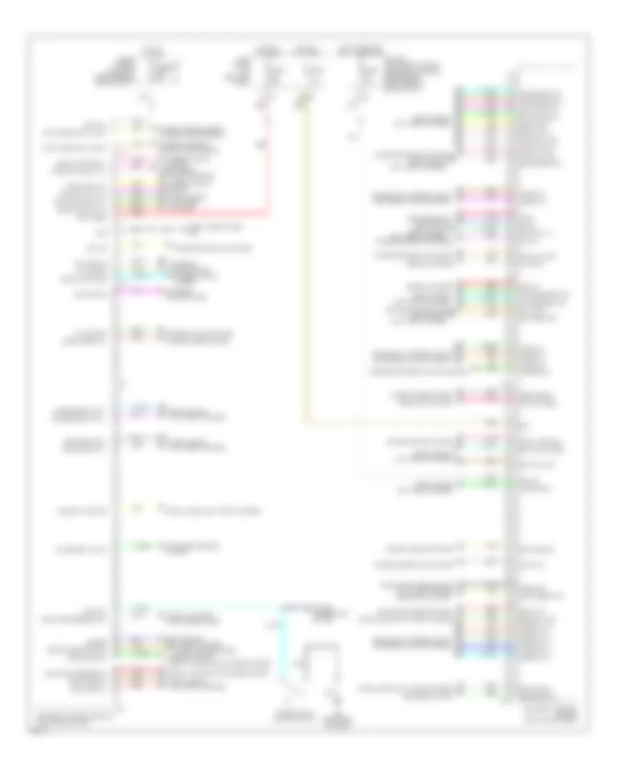
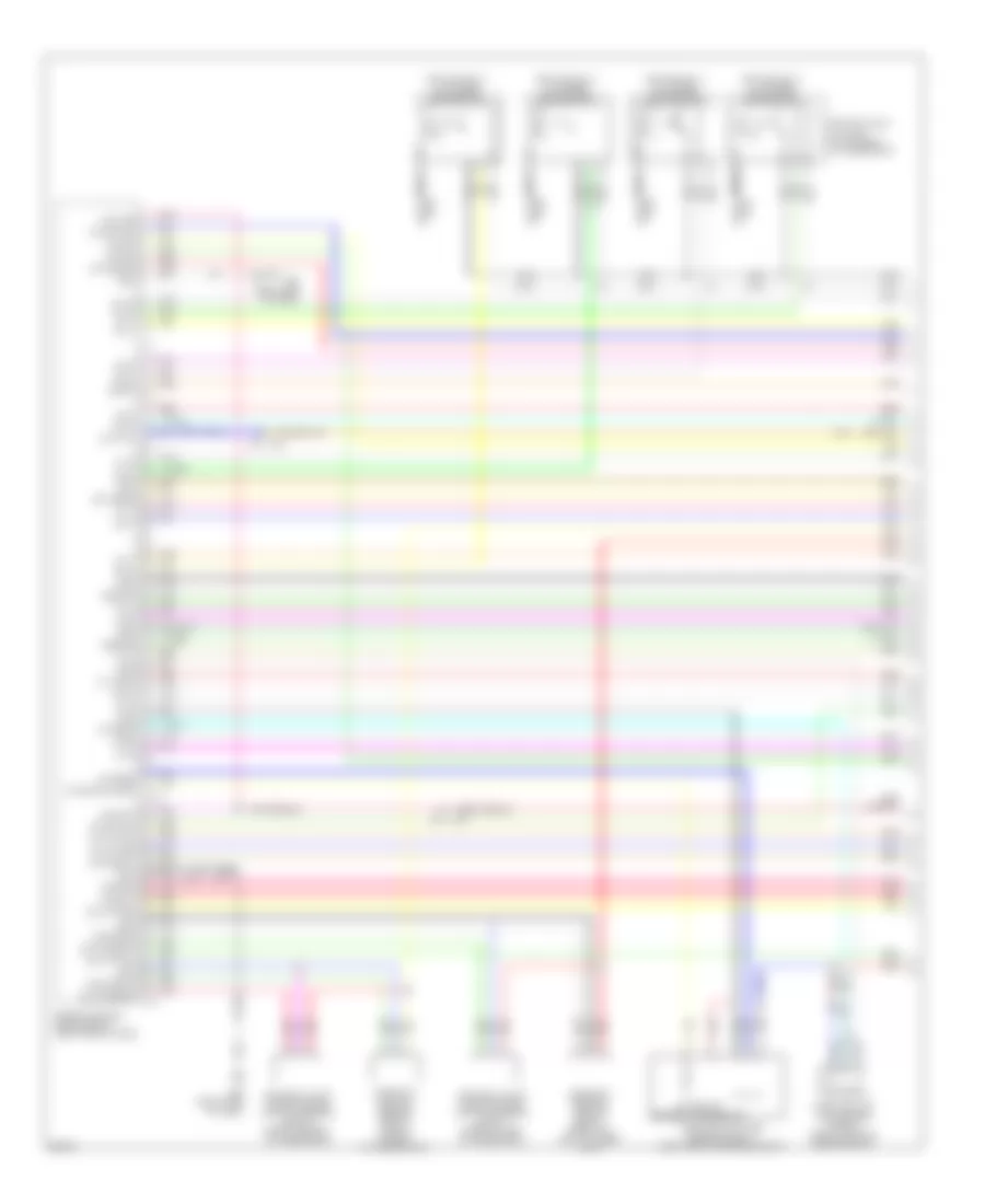
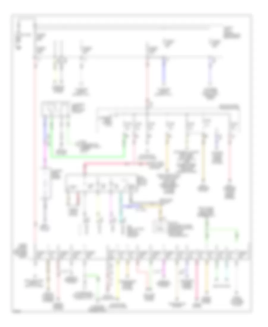
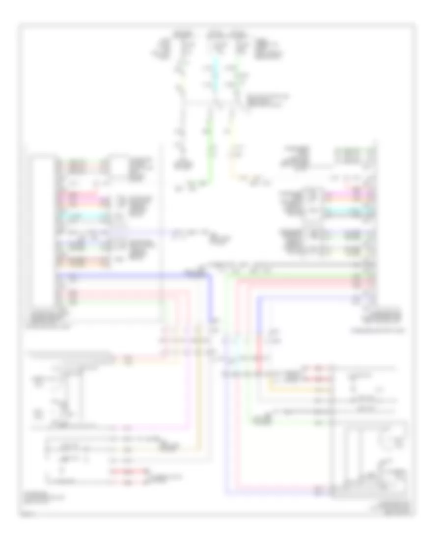
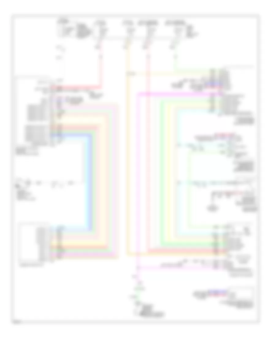
ANTI-THEFT
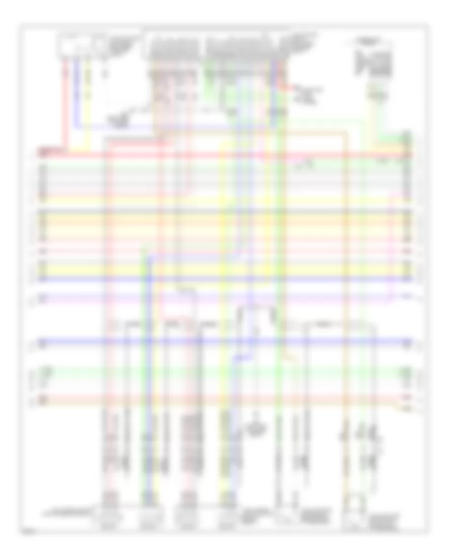
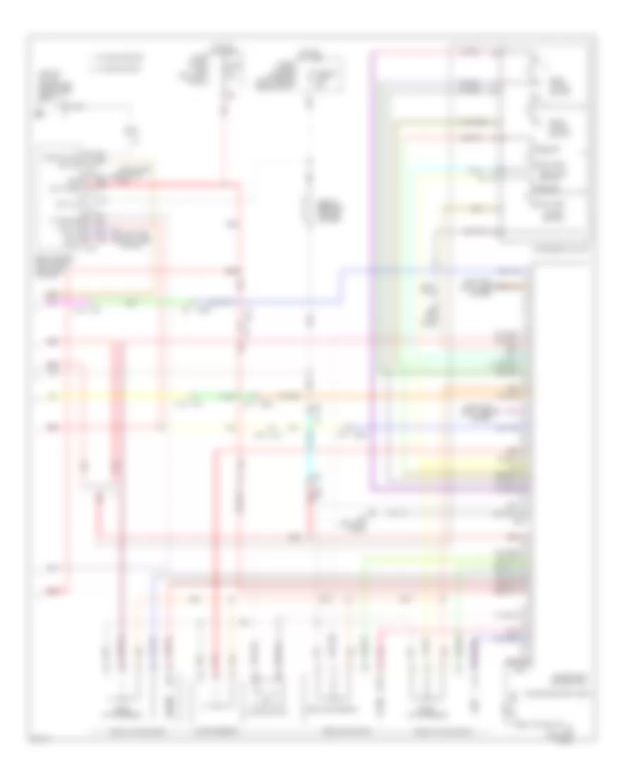
Anti-theft Wiring Diagram (1 of 4) for Infiniti FX50 2013
List of elements for Anti-theft Wiring Diagram (1 of 4) for Infiniti FX50 2013:
- (rear of driver's door) driver side door lock assembly
- (rear of front passenger's door) passenger side front door lock assembly
- (right end of dash) body control module (bcm)
- (right side of dash) m95
- Acc ind
- Back ant+
- Back ant-
- Back door opener sw
- Back door sw
- Bat (f/l)
- Bat (fuse)
- Between full stroke & n
- Buzzer
- Can-h
- Can-l
- Computer data lines system
- D1 m5
- D31
- Door lock & unlock switch
- Door lock actuator
- Dr door sen
- Dr lock out (all)
- Dr request sw
- Dr sw (drv)
- Dr sw (pass)
- Dr sw (rr lh)
- Dr sw (rr rh)
- Dr unlock out (drv)
- Dr unlock out (pass)
- Dr unlock out (rr)
- Drv dr ant+
- Drv dr ant-
- Exterior lights system
- Full stroke
- Fuse & fusible link block (right rear of engine compt)
- Fusible link l 40a
- Gnd
- Hot at all times
- Ign rly
- Inside key antenna (instrument center) (center of dash)
- Interior lights system
- Key cylinder switch
- Key slot ill cont
- Key slot sw
- Keyless entry sig
- Left front outside handle (request switch)
- Left front outside key antenna (integral to left front door handle assembly)
- Lf fr turn sig
- Lock
- Lock ind
- Lr turn sig
- Luggage room ant+
- Luggage room ant-
- M11 (left end of dash)
- M118
- M119
- M120
- M121
- M122
- M123
- M124
- M124 d31
- M5 d1
- Nats ant amp
- On ind
- Pass dr ant+
- Pass dr ant-
- Pass request sw
- Pnk
- Power window main switch
- Power windows system
- Push sw
- Pwr sply
- Pwr wdw sw comm
- Red
- Request sw
- Rh fr turn sig
- Right front outside key antenna (integral to right front door handle assembly)
- Room ant1+
- Room ant1-
- Room lamp timer
- Rr turn sig
- Security ind out
- Sensor gnd
- Shift n/p
- Shift p
- St relay cont
- Stop lamp sw1
- Stop lamp sw2
- Tan
- Unlock
- Unlock sensor
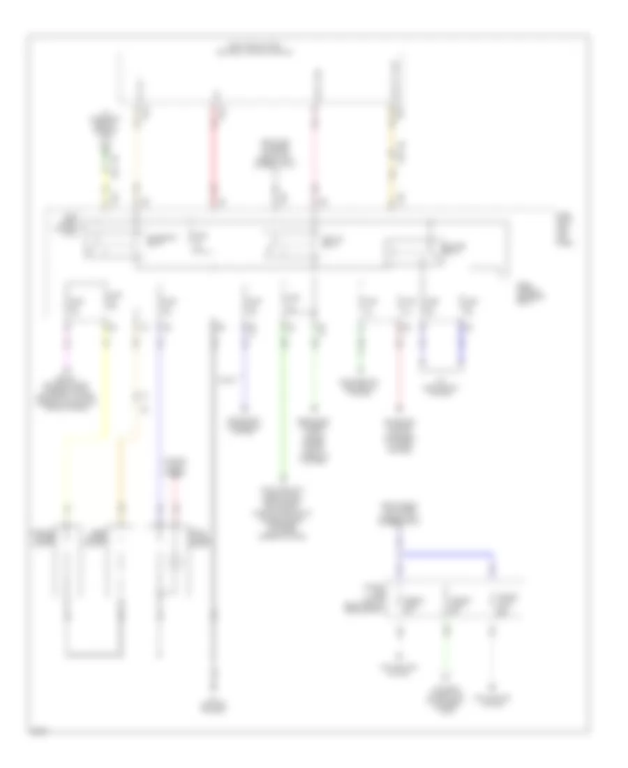
Anti-theft Wiring Diagram (2 of 4) for Infiniti FX50 2013
List of elements for Anti-theft Wiring Diagram (2 of 4) for Infiniti FX50 2013:
- (center front of luggage compt) inside key antenna (luggage room)
- (lower right side of back door) outside key antenna (back door)
- (rear of left rear door) left rear door lock assembly
- (rear of right rear door) right rear door lock assembly
- (right side of luggage compt) fuel lid lock actuator
- Acc
- B1 m7
- B18
- B201 m117
- B218
- Back door opener request switch
- Back door opener switch
- Batt
- D102 b28
- D103 (center rear of roof)
- D31
- D31 m124
- D51
- D71
- Door lock & unlock switch
- Gnd
- Ill
- Interior lights system
- Lock
- M117 b201
- M124
- M95 (right side of dash)
- Passenger side front power window switch
- Pnk
- Push switch
- Push- button ignition switch
- Red
- Remote keyless entry receiver (right end of dash)
- Right front outside handle (request switch)
- Sig out
- Tan
Anti-theft Wiring Diagram (3 of 4) for Infiniti FX50 2013
List of elements for Anti-theft Wiring Diagram (3 of 4) for Infiniti FX50 2013:
- (left "c" pillar) left rear door switch
- (or pnk)
- (right "c" pillar) right rear door switch
- 3.7l
- 5.0l
- A/t assembly (on transmission)
- A/t shift selector (detection switch)
- B201
- Bat
- Clock
- Computer data lines system
- Cpu
- Data
- E10
- E106
- E22 (right side of engine compt)
- E46 (left rear of engine compt)
- F10
- Fuse 15a
- Gnd
- Headlamp high relay
- Headlamp low relay
- Headlights system
- Hood switch (right front of engine compt)
- Horns system
- Hot at all times
- Ill
- Ill bat key slot
- Intelligent key warning buzzer (engine room) (right front of engine compt)
- Ipdm e/r (intelligent power distribution module engine room) (right rear of engine compt)
- Joint connector
- M117
- M6 e106
- M95 (right side of dash)
- Pnk
- Red
- Sig sw
- Starter control relay
- Starter relay
- Starting/ charging system
- Tan
- Transmission control module (tcm)
Anti-theft Wiring Diagram (4 of 4) for Infiniti FX50 2013
List of elements for Anti-theft Wiring Diagram (4 of 4) for Infiniti FX50 2013:
- (right "b" pillar)
- 12c
- Acc
- Amp-lcd
- Amp-meter
- B201
- B24 (left "c" pillar)
- B27
- B28
- Back door switch assembly (lower center of back door)
- Buzzer
- Can-h
- Can-l
- Combination meter
- Computer data lines system
- Cruise control system
- D101
- D102
- Driver side front door switch (left "b" pillar)
- E103
- Fuse 10a
- Fuse block (j/b) (left kick pedal)
- Gnd
- Hot at all times
- Hot in acc or on
- Hot in on or start
- Ign
- Key ind
- Lcd-amp
- M11 (left end of dash)
- M117
- M66
- M67
- Meter-amp
- Passenger side front door switch
- Pnk
- Red
- Security ind
- Stop lamp switch (on brake pedal bracket)
- Tan
- Unified meter & a/c amplifier (center of dash)
- Unified meter control unit
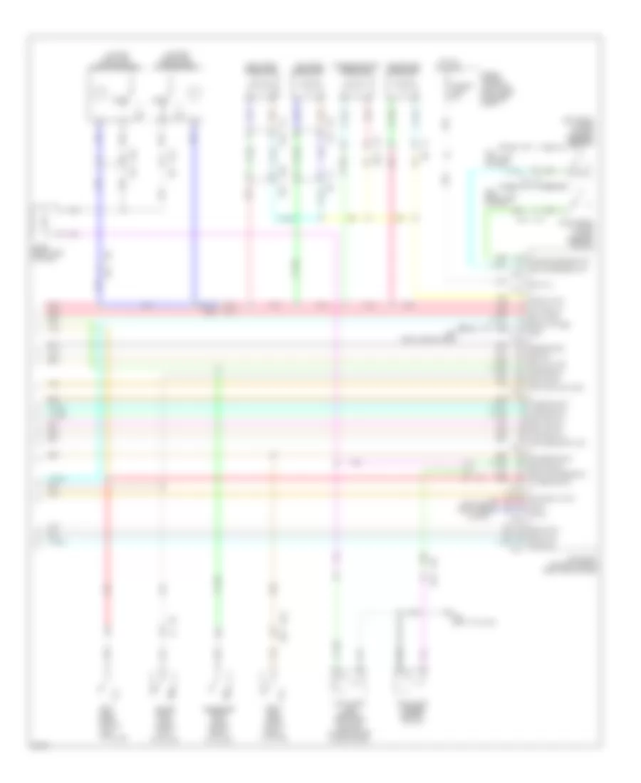
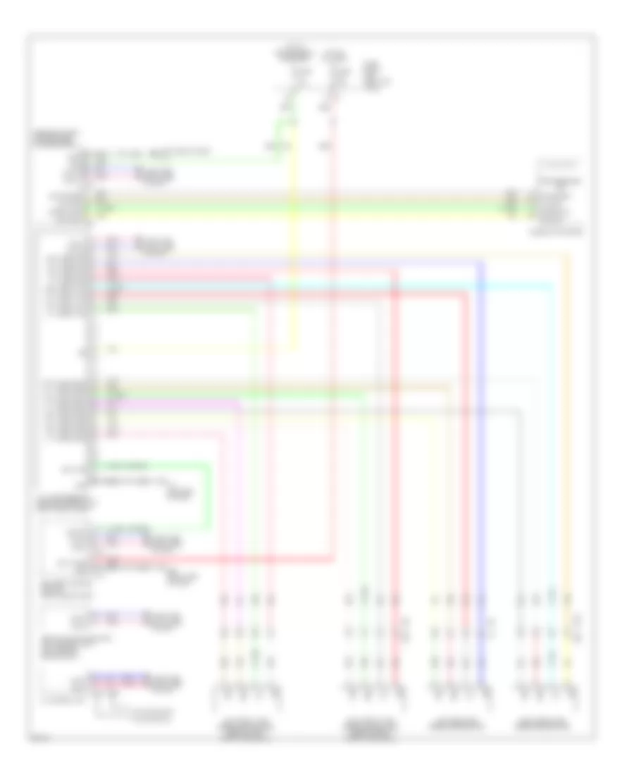
BODY CONTROL MODULES
Body Control Modules Wiring Diagram for Infiniti FX50 2013
List of elements for Body Control Modules Wiring Diagram for Infiniti FX50 2013:
- (right side of dash) m95
- 7a m1
- 9b m2
- A/t shift
- Acc ind
- Acc rly cont
- Air conditioning system
- Back door ant+
- Back door ant-
- Back door opener sw
- Back door request sw
- Back door sw
- Bat
- Bat (f/l)
- Bat (fuse)
- Bcm (body control module) (right end of dash)
- Buzzer
- Can-h
- Can-l
- Combi in 1
- Combi in 2
- Combi in 3
- Combi in 4
- Combi in 5
- Combi out 1
- Combi out 2
- Combi out 3
- Combi out 4
- Combi out 5
- Computer data lines system
- Cruise control system
- Defogger system
- Door locks & anti-theft systems
- Door locks, headlights & anti-theft systems
- Dr lock out (all)
- Dr sw (drv)
- Dr sw (rr lh)
- Dr sw (rr rh)
- Dr unlock sens
- Drv door ant+
- Drv door ant-
- Drv dr unlock out
- Drv request sw
- Exterior lights system
- Fuse & fusible link block (right rear of engine compt)
- Fuse 10a
- Fuse block (j/b) (left kick panel)
- Fusible link l 40a
- Gnd
- Hazard sw
- Headlights system
- Headlights, interior lights & exterior lights systems
- Hot at all times
- Hot w/ ignition relay energized
- Ign f/b
- Ign relay ipdm e/r
- Ign rly cont
- Immo ant ctrl
- Immo ant sig
- Interior lights & trunk, tailgate, fuel doors systems
- Interior lights system
- Ipdm e/r (intelligent power distribution module engine room) (right rear of engine compt)
- Key slot ill
- Key slot sw
- Keyless entry
- Keyless pwr
- Lf turn sig
- Light sens pwr
- Lock ind
- Lr turn sig
- Luggage room ant1+
- Luggage room ant1-
- M118
- M119
- M120
- M121
- M122
- M123
- M95 (right side of dash)
- Memory systems
- On ind
- Optical sens
- Pass door ant+
- Pass door ant-
- Pass dr sw
- Pass dr unlock out
- Pass request sw
- Pnk
- Power distribution system
- Power windows & power tops systems
- Power windows system
- Power windows, seats & power tops systems
- Push button ignition switch
- Push sw
- Pwr window sply (bat)
- Pwr window sply (rap)
- Pwr wnd sw
- Rear def out
- Rear wiper out
- Rear wiper stop pos
- Red
- Rf turn sig
- Rly cont
- Room ant1+
- Room ant1-
- Room lamp timer
- Room lp pwr sply
- Rr dr unlock out
- Rr turn sig
- Security ind
- Sens gnd
- Sens serial
- Shift n/p
- Shift p
- Starter rly cont
- Starting/charging system
- Step lamp out
- Stop lamp sw 2
- Tan
- Trunk, tailgate, fuel doors system
- Warning & exterior lights systems
- Wiper/washer system
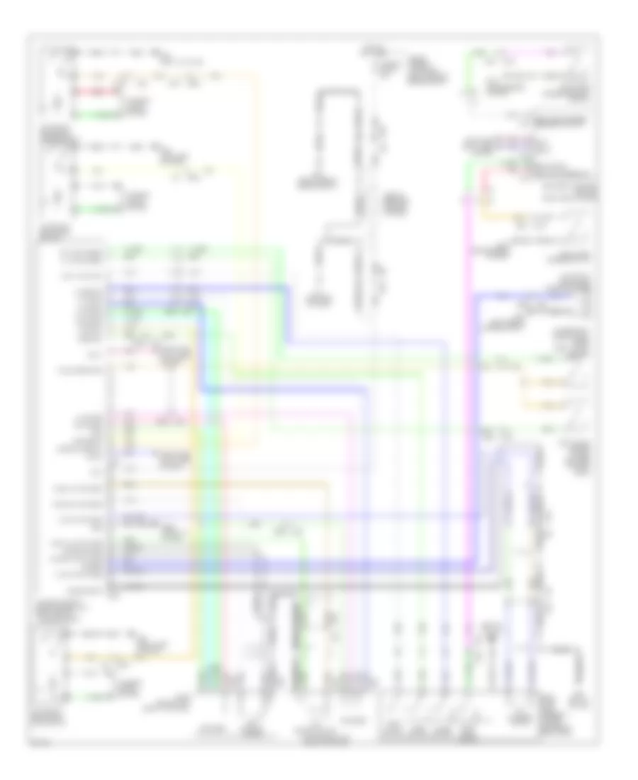
COMPUTER DATA LINES
Computer Data Lines Wiring Diagram, with ICC (1 of 2) for Infiniti FX50 2013
List of elements for Computer Data Lines Wiring Diagram, with ICC (1 of 2) for Infiniti FX50 2013:
- (left side of dash)
- (left side of dash) m55
- (or pnk)
- (right side of dash) low tire pressure warning control unit
- 3.7l
- 3.7l 5.0l
- 5.0l
- A/t assembly (on transmission)
- Accelerator pedal actuator
- Air bag diagnosis sensor unit (under rear of center console)
- Automatic back door control unit (right side of luggage compt)
- Awd control unit (awd) (right end of dash)
- B201
- B202 (right kick panel)
- B207
- B224 (right "c" pillar)
- Bcm (body control module) (right end of dash)
- Can comm line
- Can comm-h
- Can comm-l
- Can-h
- Can-l
- Comm line
- Connector
- Data link
- Data link connector (left side of dash)
- Driver side pre crash seat belt control unit (base of left "b" pillar)
- E-suspension control unit (w/ ras) (left side of luggage compt)
- E10
- E106
- Ecm (engine control module) (right end of dash)
- F10
- F103
- F111
- F113
- Fuse 3 10a
- Fuse 6 10a
- Fuse block (j/b) (left kick panel)
- Hot at all times
- Hot in on or start
- Its comm-h
- Its comm-l
- Joint
- K-line
- Lane camera unit (center front of roof)
- M110
- M116
- M117
- M122
- M160
- M164
- M224
- M67
- Nca
- Occupant detection system control unit (under front passenger's seat)
- Pnk
- Ras control unit (if equipped)
- Red
- Sonar control unit (w/ navigation)
- Tan
- Tcm (transmission control module)
- Unified meter & a/c amplifier (center of dash)
- Vvel control module (right rear of engine compt)
Computer Data Lines Wiring Diagram, with ICC (2 of 2) for Infiniti FX50 2013
List of elements for Computer Data Lines Wiring Diagram, with ICC (2 of 2) for Infiniti FX50 2013:
- (left end of dash) afs control unit
- (right "c" pillar)
- (under driver's seat) (w/ navigation) around view monitor control unit
- (w/ memory)
- Abs actuator & electric unit (control unit) (left rear of engine compt)
- Av comm (h)
- Av comm (l)
- Av control unit
- B11
- B201
- B202 (right kick panel)
- B224
- B451
- B46
- B460
- B88
- Battery
- Brake booster control unit (right side of luggage compt)
- Can gateway (right end of dash)
- Can-h
- Can-l
- Cpu
- Ddl2
- Driver seat control unit
- E106
- Front seat (driver side)
- Fuse 11 10a
- Fuse block (j/b) (left kick panel)
- Gnd
- Hot at all times
- Icc sensor integrated unit (lower left front of engine compt)
- Ignition
- Ipdm e/r (intelligent power distribution module engine room) (right rear of engine compt)
- Its comm-h
- Its comm-l
- M117
- M204
- M210
- M25
- M55 (left side of dash)
- Multi-function switch
- Nca
- Pnk
- Steering angle sensor (on steering column)
- Tan
- Tel adapter unit (w/o navigation) (right rear of luggage compt)
- Total illumination control unit (right side of dash)
- W/ navigation
- W/o navigation
Computer Data Lines Wiring Diagram, without ICC for Infiniti FX50 2013
List of elements for Computer Data Lines Wiring Diagram, without ICC for Infiniti FX50 2013:
- (left side of dash) m55
- (or pnk)
- (right side of dash) total illumination control unit
- (w/ memory) front seat (driver side)
- 3.7l
- 5.0l
- A/t assembly (on transmission)
- Abs actuator & electric unit (control unit) (left rear of engine compt)
- Air bag diagnosis sensor unit (under rear of center console)
- Around view monitor control unit (w/ navigation) (under driver's seat)
- Automatic back door control unit (right side of luggage compt)
- Av comm (h)
- Av comm (l)
- Av control unit
- Awd control unit (awd) (right end of dash)
- B11
- B201
- B201 pnk
- B202 (right kick panel)
- B207
- B224 (right "c" pillar)
- B451
- B46
- B460
- B88
- Bcm (body control module) (right end of dash)
- Can comm
- Can comm line
- Can comm-h
- Can comm-l
- Can-h
- Can-l
- Comm line
- Cpu
- Data link
- Data link connector (left side of dash)
- Ddl 2
- Driver seat control unit
- E10
- E106
- Ecm (engine control module) (right end of dash)
- F10
- F103
- F111
- F113
- Fuse 3 10a
- Fuse 6 10a
- Fuse block (j/b) (left kick panel)
- Hot at all times
- Hot in on or start
- Ipdm e/r (intelligent power distribution module engine room) (right rear of engine compt)
- J/c
- K-line
- Low tire pressure warning control unit (right side of dash)
- M116
- M117
- M122
- M160
- M164
- M204
- M210
- M224
- M25
- M67
- M7 pnk
- Multi-function switch
- Nca
- Occupant detection system control unit (under front passenger's seat)
- Pnk
- Red
- Sonar control unit (w/ navigation)
- Steering angle sensor (on steering column)
- Tan
- Tcm (transmission control module)
- Tel adapter unit (w/o navigation) (right rear of luggage compt)
- Unified meter & a/c amplifier (center of dash)
- Vvel control module (right rear of engine compt)
- W/ memory
- W/ navigation
- W/o memory
- W/o navigation
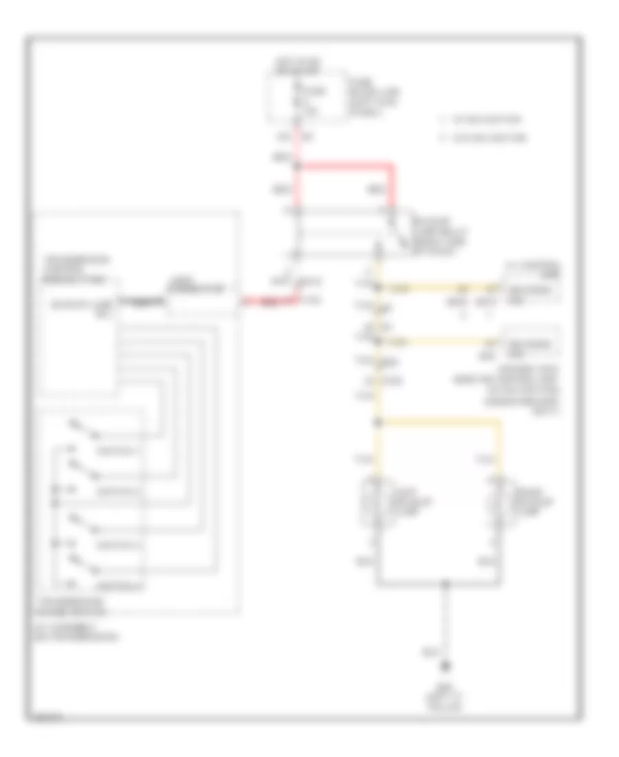
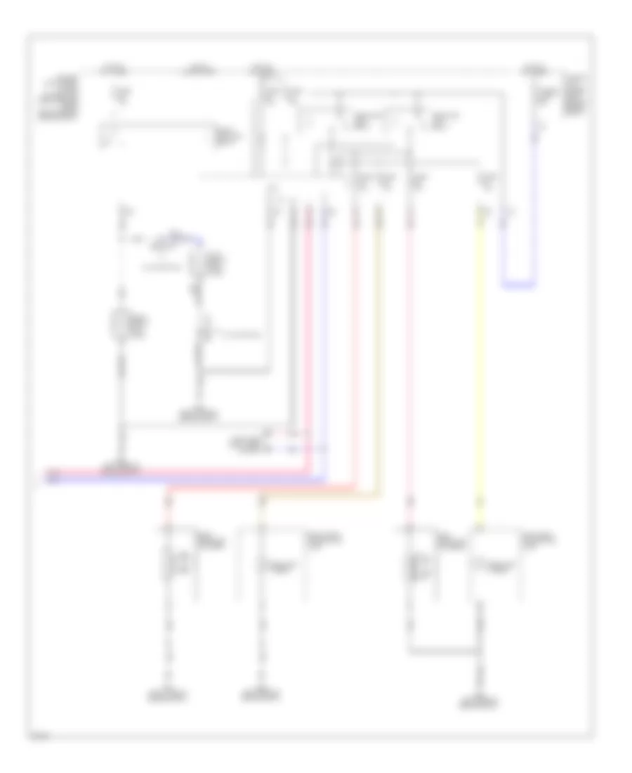
COOLING FAN
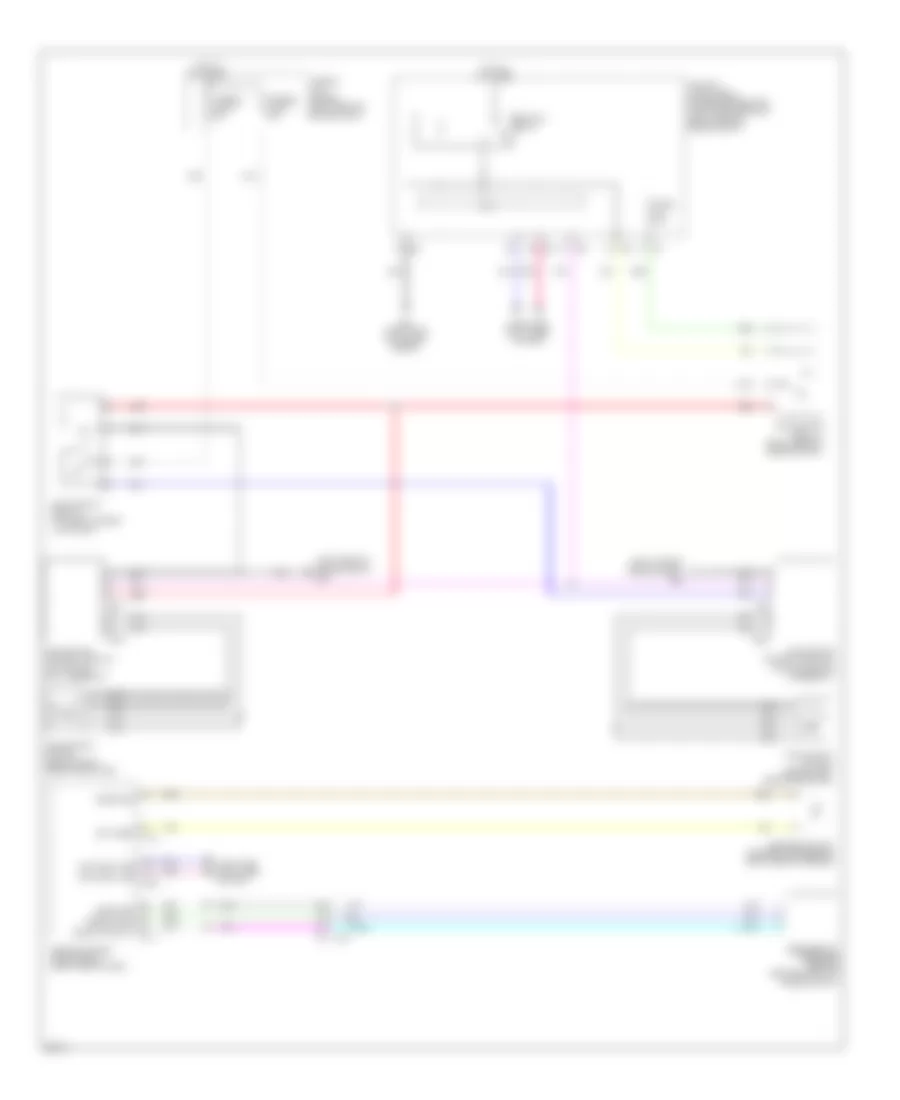
Cooling Fan Wiring Diagram for Infiniti FX50 2013
List of elements for Cooling Fan Wiring Diagram for Infiniti FX50 2013:
- (left rear of engine compt) e46
- (right side of engine compt) e22
- Can comm line
- Computer data lines system
- Cooling fan control module 1 (on cooling fan 1 assembly)
- Cooling fan control module 2 (on cooling fan 2 assembly)
- Cooling fan motor 1 (behind right side of radiator)
- Cooling fan motor 2 (behind left side of radiator)
- Cooling fan relay 1 (right rear of engine compt)
- Cooling fan relay 2 (in fuse & fusible link block)
- Cpu
- E22 (right side of engine compt)
- E301
- E303
- E37
- E38
- Ect snsr
- Engine control module (ecm) (right end of dash)
- Engine coolant temperature sensor (right rear of engine)
- F10 e10
- F110
- F111
- Fuse 10a
- Fusible link holder (right rear of engine compt)
- Fusible link o 50a
- Fusible link s 50a
- Hot at all times
- Ignition relay
- Ipdm e/r (intelligent power distribution module engine room) (right rear of engine compt)
- M160
- Nca
- Pnk
- Press snsr
- Red
- Refrigerant pressure sensor (center front of engine compt)
- Snsr gnd
- Snsr pwr sply
CRUISE CONTROL
Cruise Control Wiring Diagram (1 of 2) for Infiniti FX50 2013
List of elements for Cruise Control Wiring Diagram (1 of 2) for Infiniti FX50 2013:
- (or pnk)
- (or red)
- (top left side of engine) electric throttle control actuator (bank 1)
- 4f e103
- Accelerator pedal position sensor (integral to accelerator pedal assembly)
- Amp-lcd
- Amp-meter
- Ascd brake switch (on brake pedal bracket)
- Bat
- Can-h
- Can-l
- Close
- Combination meter
- Computer data lines system
- Cruise (lcd) ind
- E10
- E103
- E106
- E106 m6
- Ecm (engine control module) (right end of dash)
- Ecm relay
- Engine controls system
- F10
- F110
- F111
- Fuse 10a
- Fuse 15a
- Fuse block (j/b) (left kick panel)
- Gnd
- Hot at all times
- Hot in on or start
- Ign
- Ipdm e/r (intelligent power distribution module engine room) (right rear of engine compt)
- Lcd-amp
- M1 2a
- M11 (left end of dash)
- M160
- M66
- M67
- M95 (right side of dash)
- Meter-amp
- Nca
- Open
- Pnk
- Red
- Sensor 1
- Sensor 2
- Set ind
- Stop lamp switch (on brake pedal bracket)
- Tan
- Throttle control motor
- Throttle control motor relay
- Throttle position sensor
- Unified meter & a/c amplifier (center of dash)
Cruise Control Wiring Diagram (2 of 2) for Infiniti FX50 2013
List of elements for Cruise Control Wiring Diagram (2 of 2) for Infiniti FX50 2013:
- A/t assembly (on transmission)
- Accel/ resume
- Ascd steering switch
- Can-h
- Can-l
- Cancel
- Close
- Combination switch (spiral cable)
- Computer data lines system
- Electric throttle control actuator (bank 2) (top right side of engine)
- Input speed sensor 1
- Input speed sensor 2
- Joint connector
- M303
- M36
- M95 (right side of dash)
- Main (on/off)
- Nca
- Open
- Output speed sensor
- Pnk
- Red
- Sensor 1
- Sensor 2
- Set/ coast
- Tcm (transmission control module)
- Throttle control motor
- Throttle position sensor
- Transmission range switch
Intelligent Cruise Control Wiring Diagram (1 of 2) for Infiniti FX50 2013
List of elements for Intelligent Cruise Control Wiring Diagram (1 of 2) for Infiniti FX50 2013:
- (left rear of engine compt) e46
- (lower left front of engine compt) icc sensor integrated unit
- (right "c" pillar) b224
- A/t assembly (on transmission)
- B201
- B201 m117
- B202 (right kick panel)
- B249
- B250
- Batt
- Booster solenoid
- Brake booster (left rear corner of engine compt)
- Brake booster control unit (right side of luggage compt)
- Brake booster pressure sensor (left rear of engine compt)
- Can-h
- Can-l
- Chime sig
- Comm-h
- Comm-l
- Computer data lines system
- Drive sig
- E106
- E46 (left rear of engine compt)
- Fuse & fusible link block (right rear of engine compt)
- Fuse 10a
- Fuse 45 10a
- Fuse 50 15a
- Gnd
- Hot at all times
- Hot in on or start
- Iba off sw
- Iba off switch
- Icc brake hold relay (in fuse & fusible link block)
- Icc brake switch (on brake pedal bracket)
- Icc warning chime (left end of dash)
- Ign
- Input speed sensor 1
- Interior lights system
- Ipdm e/r (intelligent power distribution module engine room) (right rear of engine compt)
- Its comm-h
- Its comm-l
- Joint connector
- M11 (left end of dash)
- M117
- M6 e106
- Nca
- Output speed sensor
- Pnk
- Red
- Release sw
- Release switch
- Sen gnd
- Sen pwr
- Sen sig
- Sol gnd
- Sol pwr
- Tan
- Tcm (transmission control module)
- Transmission range switch
Intelligent Cruise Control Wiring Diagram (2 of 2) for Infiniti FX50 2013
List of elements for Intelligent Cruise Control Wiring Diagram (2 of 2) for Infiniti FX50 2013:
- (3.7l)
- (5.0l)
- (on/off) main
- (or red)
- 3.7l
- 5.0l
- Accel/ resume
- Accelerator pedal actuator (w/ das) (left side of dash)
- Accelerator pedal position sensor (integral to accelerator pedal assembly)
- Amp-lcd
- Amp-meter
- Aps1
- Aps2
- Ascdsw
- Assistance driver dynamic
- Avcc-aps1
- Avcc-aps2
- Batt
- Battery
- Bnc sw
- Brake
- Can-h
- Can-l
- Cancel
- Combination meter
- Combination switch (spiral cable)
- Comm-h
- Comm-l
- Computer data lines system
- Cruise ind
- Distance
- E10
- E103
- E106
- E106 m6
- E46 (left rear of engine compt)
- Ecm (engine control module) (right end of dash)
- Exterior lights system
- F10
- F113
- Fuse & fusible link block (right rear of engine compt)
- Fuse 10a
- Fuse block (j/b) (left kick panel)
- Gnd
- Gnd-a
- Gnda
- Gnda-aps1
- Hot at all times
- Hot w/ ignition relay energized
- Icc steering switch
- Ign
- Ignition
- Lcd-amp
- M11 (left end of dash)
- M160
- M164
- M303
- M36
- M66
- M67
- M95 (right side of dash)
- Meter-amp
- Nca
- Pnk
- Red
- Sensor 1
- Sensor 2
- Set/ coast
- Stop lamp switch (on brake pedal bracket)
- Tan
- Unified meter & a/c amplifier (center of dash)
- Vehcan h1
- Vehcan l1
DEFOGGERS
Defoggers Wiring Diagram for Infiniti FX50 2013
List of elements for Defoggers Wiring Diagram for Infiniti FX50 2013:
- 10c
- 11g
- Av comm (h)
- Av comm (l)
- Av control unit
- B27
- B6 10g
- Bat (f/l)
- Bat (fuse)
- Bcm (body control module) (right end of dash)
- Can-h
- Can-l
- Computer data lines system
- D101
- D103 (center rear of roof)
- D108
- D120
- D31
- Driver door mirror (door mirror defogger) (front of driver's door)
- E101
- Fuse & fusible link block (right rear of engine compt)
- Fuse 10a
- Fuse 20a
- Fuse block (j/b) (left kick panel)
- Fusible link e 100a
- Fusible link holder (right rear of engine compt)
- Fusible link l 40a
- Gnd
- Hot at all times
- Hot in on or start
- M11 (left end of dash)
- M118
- M119
- M122
- M124
- M2 4b
- M204
- M210
- M3 9c
- M95 (right side of dash)
- Multi-function switch (rear window defogger switch)
- Passenger door mirror (door mirror defogger) (front of front passenger's door)
- Pnk
- Rear window def rly cont m123
- Rear window defogger
- Rear window defogger relay
- Red
- Tan
- W/ navigation
- W/o navigation
ELECTRONIC POWER STEERING
Electronic Power Steering Wiring Diagram, with RAS for Infiniti FX50 2013
List of elements for Electronic Power Steering Wiring Diagram, with RAS for Infiniti FX50 2013:
- (left end of dash)
- B1 m7
- B61 (left side of luggage compt)
- B62 (left rear of luggage compt)
- Bat
- Can-h
- Can-l
- Combination meter
- Comm
- Computer data lines system
- E103
- E106
- E121
- Eps sol +
- Exterior lights system
- F103
- Fuse & fusible link block (right rear of engine compt)
- Fuse 10a
- Fuse 20a
- Fuse block (j/b) (left kick panel)
- Gnd
- Hot at all times
- Hot in on or start
- Ign
- Intelligent power distribution module engine room (ipdm e/r) (right rear of engine compt)
- Lh mtr
- M11
- M11 (left end of dash)
- M116
- M66
- M67
- M7 b1
- Mtr pwr sply
- Pnk
- Power steering solenoid valve
- R motor gnd
- R-ang sen gnd
- R-ang sen main sig
- R-ang sen sub sig
- R-ang sen vcc
- R-mtr rly
- Ras
- Ras control unit
- Ras motor
- Ras motor relay (left side of luggage compt)
- Rear wheel steering angle sensor
- Red
- Rh mtr
- Stop lamp sw
- Tan
- Unified meter & a/c amplifier (center of dash)
Electronic Power Steering Wiring Diagram, without RAS for Infiniti FX50 2013
List of elements for Electronic Power Steering Wiring Diagram, without RAS for Infiniti FX50 2013:
- (center of dash) unified meter & a/c amplifier
- 3.7l
- 5.0l
- Can-h
- Can-l
- Computer data lines system
- E106
- Eng spd output sig m164
- Eng tacho
- Engine control module (ecm) (right end of dash)
- Eps sol+
- Eps sol-
- F103
- Fuse 10a
- Gnd
- Hot w/ ignition relay energized
- Ign
- Ipdm e/r (intelligent power distribution module engine room) (right rear of engine compt)
- M11 (left end of dash)
- M116
- M160
- M66
- M67
- Pnk
- Power steering control unit (right side of dash)
- Power steering solenoid valve
- Red
- Vehicle speed
- Vsp
ENGINE PERFORMANCE
5.0L
5.0L, Engine Performance Wiring Diagram (1 of 6) for Infiniti FX50 2013
List of elements for 5.0L, Engine Performance Wiring Diagram (1 of 6) for Infiniti FX50 2013:
- (ignition coils 2, 4, 6 & 8: top of right cylinder bank)
- A/f snsr
- Afh-b1
- Afh-b2
- Camshaft position sensor (bank 1) (front of left cylinder bank)
- Camshaft position sensor (bank 2) (front of right cylinder bank)
- E10
- Ect senr
- Engine control module (ecm) (right end of dash)
- Evap
- Ex cvtc-b1
- Ex cvtc-b2
- Ex phase-b1
- Ex phase-b2
- Exhaust valve timing control position sensor (bank 1) (front of left cylinder bank)
- Exhaust valve timing control position sensor (bank 2) (front of right cylinder bank)
- F10
- F103
- F110
- F111
- Gnd
- Ign 1
- Ign 2
- Ign 3
- Ign 4
- Ign 5
- Ign 6
- Ign 7
- Ign 8
- Ignition coil 2 (w/ power transistor)
- Ignition coil 4 (w/ power transistor)
- Ignition coil 6 (w/ power transistor)
- Ignition coil 8 (w/ power transistor)
- In cvtc-b1
- In cvtc-b2
- Inj 1
- Inj 2
- Inj 3
- Inj 4
- Inj 5
- Inj 6
- Inj 7
- Inj 8
- Intake air temp
- Intake air temperature sensor
- Knk1
- Knk2
- M116
- M95 (right side of dash)
- Mass air flow (maf) sensor (bank 1) (left front of engine compt)
- Mass air flow (maf) sensor (bank 2) (right front of engine compt)
- Mot rly
- Motor1-b1
- Motor1-b2
- Motor2-b1
- Motor2-b2
- Nca
- O2hr-b1
- O2hr-b2
- O2sr-b1
- O2sr-b2
- Oil temp
- Plug spark
- Pnk
- Pos snsr
- Pos snsr 2
- Red
- Spark plug
- Ssoff
- Tan
- Vmot-b1
- Vmot-b2
5.0L, Engine Performance Wiring Diagram (2 of 6) for Infiniti FX50 2013
List of elements for 5.0L, Engine Performance Wiring Diagram (2 of 6) for Infiniti FX50 2013:
- (ignition coils 1, 3, 5 & 7: top of left cylinder bank)
- Condenser (left front of engine compt)
- E10 f10
- Evap canister purge volume control solenoid valve
- Exhaust valve timing control solenoid valve (bank 1) (front of left cylinder bank)
- Exhaust valve timing control solenoid valve (bank 2) (front of right cylinder bank)
- F103
- F34 (left front of engine)
- F49 f211
- Ignition coil 1 (w/ power transistor)
- Ignition coil 3 (w/ power transistor)
- Ignition coil 5 (w/ power transistor)
- Ignition coil 7 (w/ power transistor)
- Intake valve timing control solenoid valve (bank 1) (front of left cylinder bank)
- Intake valve timing control solenoid valve (bank 2) (front of right cylinder bank)
- Knock sensor (bank 1) (top center of left cylinder bank)
- Knock sensor (bank 2) (top center of right cylinder bank)
- M116
- Nca
- Plug spark
- Pnk
- Red
- Shield
- Spark plug
- Tan
5.0L, Engine Performance Wiring Diagram (3 of 6) for Infiniti FX50 2013
List of elements for 5.0L, Engine Performance Wiring Diagram (3 of 6) for Infiniti FX50 2013:
- (or pnk)
- (or red)
- Close
- Computer data lines system
- Cooling fans system
- Cpu
- E10
- E106
- E106 m6
- E22 (right side of engine compt)
- E46 (left rear of engine compt)
- Ecm relay
- Electric throttle control actuator (bank 1) (top left side of engine)
- Engine coolant temperature sensor (right rear of engine)
- Engine oil temperature sensor
- F10
- F10 e10
- Fuel pump relay
- Fuse 10a
- Fuse 15a
- Heated oxygen sensor 2 (bank 1) (left front of engine)
- Heated oxygen sensor 2 (bank 2) (right front of engine)
- Hot at all times
- Hot in on or start
- Ignition relay
- Ipdm e/r (intelligent power distribution module engine room) (right rear of engine compt)
- M95 (right side of dash)
- Nca
- Open
- Pnk
- Red
- Sensor 1
- Sensor 2
- Snow mode switch
- Tan
- Throttle control motor
- Throttle control motor relay
- Throttle position sensor
5.0L, Engine Performance Wiring Diagram (4 of 6) for Infiniti FX50 2013
List of elements for 5.0L, Engine Performance Wiring Diagram (4 of 6) for Infiniti FX50 2013:
- (fuel injector 1, 3, 5 & 7: top of left cylinder bank) (fuel injector 2, 4, 6 & 8: top of right cylinder bank)
- (left "c" pillar) b24
- (left "c" pillar) fuel pump control module
- (or pnk)
- (or red)
- Air fuel ratio (a/f) sensor 1 (bank 1) (right rear of engine)
- Air fuel ratio (a/f) sensor 1 (bank 2) (left rear of engine)
- B101
- B102
- B201
- Bat
- Battery current sensor (on battery)
- Close
- Diag out sig
- E10
- E121
- Electric throttle control actuator (bank 2) (top right side of engine)
- Evap control system pressure sensor (if equipped)
- F10
- F103
- F121 f60
- F122 f69
- Fpc in sig
- Fuel injector
- Fuel level sensor unit & fuel pump (main) (in fuel tank)
- Fuel pump
- Fuel pump +
- Fuel pump -
- Fuel tank tempe- rature sensor
- Fuse & fusible link block (right rear of engine compt)
- Fusible link g 50a
- Gnd
- Hot at all times
- Instrument cluster system
- M116
- M117
- M95 (right side of dash)
- Manifold absolute pressure sensor (top center rear of engine)
- Nca
- Open
- Pnk
- Red
- Sensor 1
- Sensor 2
- Shield
- Tan
- Throttle control motor
- Throttle position sensor
5.0L, Engine Performance Wiring Diagram (5 of 6) for Infiniti FX50 2013
List of elements for 5.0L, Engine Performance Wiring Diagram (5 of 6) for Infiniti FX50 2013:
- (or pnk)
- (or red)
- (or shield)
- Combination meter
- Comm line
- Comm-amp-lcd
- Comm-amp-mtr
- Comm-lcd-amp
- Comm-mtr-amp
- Computer data lines system
- E10
- E22 (right side of engine compt)
- F10
- Lamp
- M-rly
- Malfunction indicator
- Mod gnd
- Motor b1
- Motor1-b2
- Motor2-b1
- Motor2-b2
- Mtr rly sig
- Pwr sply
- Red
- Sensor 1
- Sensor 2
- Shield
- Snsr gnd
- Vel/s-b1
- Vel/s-b2
- Vel/s2-b1
- Vel/s2-b2
- Vmot-b1
- Vmot-b2
- Vvel actuator motor (bank 1) (rear of right cylinder bank)
- Vvel actuator motor (bank 2) (rear of left cylinder bank)
- Vvel actuator motor relay (right rear of engine compt)
- Vvel control module (right rear of engine compt)
- Vvel control shaft position sensor (bank 1)
- Vvel control shaft position sensor (bank 2)
5.0L, Engine Performance Wiring Diagram (6 of 6) for Infiniti FX50 2013
List of elements for 5.0L, Engine Performance Wiring Diagram (6 of 6) for Infiniti FX50 2013:
- (center of dash) unified meter & a/c amplifier
- (lower rear of engine) crankshaft position sensor (pos)
- (on brake pedal bracket) stop lamp switch
- (on transmission)
- (or pnk) tan
- (or red)
- A/t assembly
- Abort sig
- Accelerator pedal position sensor (integral to accelerator pedal assembly)
- Af(+)-b1
- Af(+)-b2
- Af(-)-b1
- Af(-)-b2
- Aps1
- Aps2
- Avcc-phs-b2
- B101
- B102
- B102 b101
- B201 m117
- Bat
- Batt
- Bncsw
- Brake
- Can comm line
- Can comm line ascd/icc steering sw
- Can-h
- Can-l
- Cdcv
- Comm-amp
- Comm-lcd
- Comm-mtr
- Computer data lines system
- Control module)
- Cruise control system
- Cursen
- E10
- E10 f10
- E103
- E106
- E106 m6
- Electronic power steering system
- Eng can-l
- Engcan-h
- Engine control module (right end of dash)
- Evap canister vent control valve (under right rear of vehicle)
- Evapprs
- F10
- F103 m116
- F111
- Fpcm
- Fpcmck
- Fuel lvl
- Fuel pump
- Fuse 10a
- Fuse block (j/b) (left kick panel)
- Gnd
- Hot at all times
- Hot in on or start
- Ign
- Ign sw
- Joint connector
- Kline
- M11 (left end of dash)
- M117 b201
- M160
- M6 e106
- M6 shield
- M66
- M67
- M95 (right side of dash)
- Nca
- Neut-h
- Output sig
- Pdpres
- Pnk
- Pos
- Power steering pressure sensor
- Pr sens
- Pspres
- Pwr sply
- Red
- Refrigerant pressure sensor (center front of engine compt)
- Sens pwr sply
- Sensor 1
- Sensor 2
- Shield
- Snow sw
- Snsr gnd
- Snsr pwr sply
- Tan
- Tcm (transmission
- Tps1-b1
- Tps1-b2
- Tps2-b1
- Tps2-b2
- W/ icc
- W/o icc
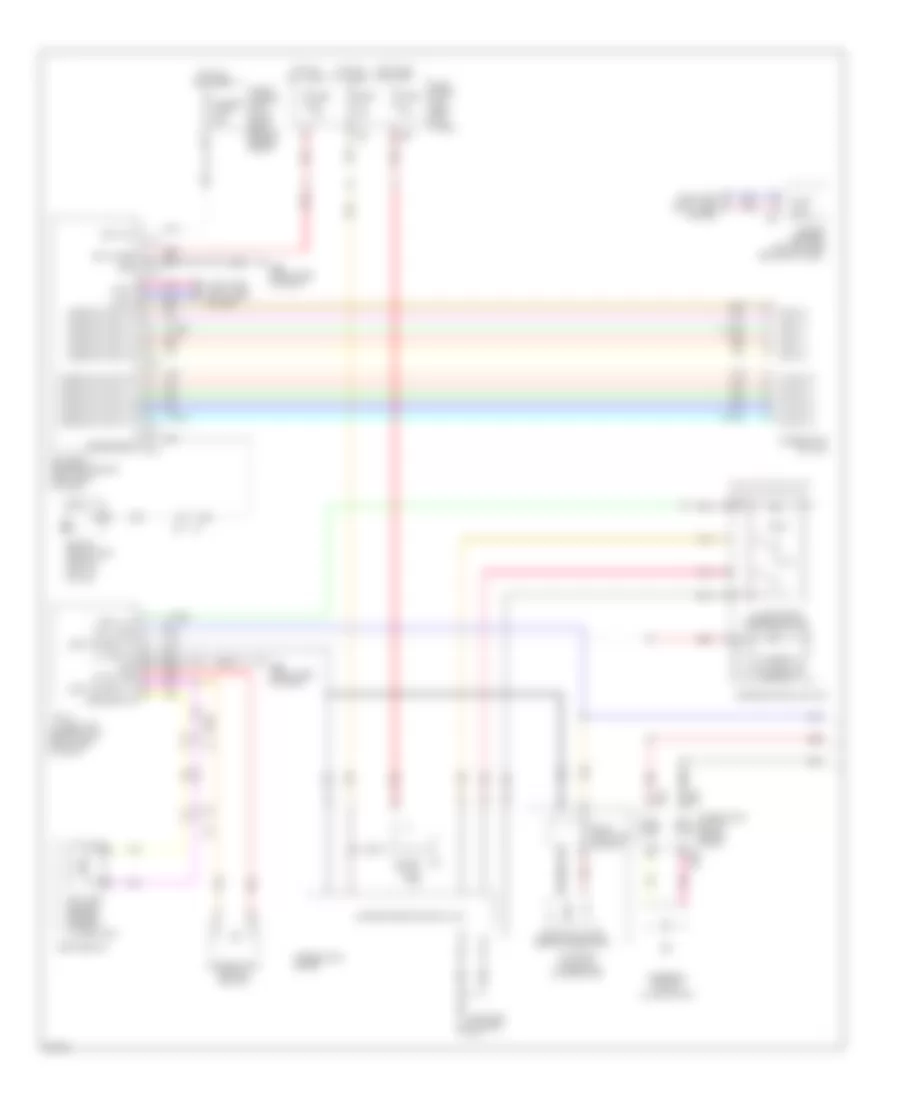
EXTERIOR LIGHTS
Backup Lamps Wiring Diagram for Infiniti FX50 2013
List of elements for Backup Lamps Wiring Diagram for Infiniti FX50 2013:
- (under driver's seat)
- 12c
- A/t assembly (on transmission)
- Around view monitor control unit (w/ navigation)
- Av control unit
- B24 (left "c" pillar)
- B46
- Backup lamp relay (right side of dash)
- Backup lamp rly
- D102
- F103
- Fuse 10a
- Fuse block (j/b) (left kick panel)
- Hot in on or start
- Joint connector
- Left backup lamp
- M204
- M210
- Nca
- Red
- Reverse sig
- Right backup lamp
- Switch 1
- Switch 2
- Switch 3
- Switch 4
- Tan
- Tan b28
- Tan m7
- Transmission control module (tcm)
- Transmission range switch
- W/ navigation
- W/o navigation
Exterior Lamps Wiring Diagram (1 of 2) for Infiniti FX50 2013
List of elements for Exterior Lamps Wiring Diagram (1 of 2) for Infiniti FX50 2013:
- (left kick panel)
- (left side of dash) m55
- B201
- B202 (right kick panel)
- B24 (left "c" pillar)
- B241
- B28
- B67
- B7 (left kick panel)
- Bat
- Bat (f/l)
- Bat (fuse)
- Bcm (body control module) (right end of dash)
- Can-h
- Can-l
- Combi sw input 1
- Combi sw input 2
- Combi sw input 3
- Combi sw input 4
- Combi sw input 5
- Combi sw output 1
- Combi sw output 2
- Combi sw output 3
- Combi sw output 4
- Combi sw output 5
- Combination meter
- Combination switch
- Comm (amp-meter)
- Comm (meter-amp)
- Computer data lines system
- D102
- Driver door sw
- E103 9f
- E104
- E106
- Fuse & fusible link block (right rear of engine compt)
- Fuse 10a
- Fuse block (j/b)
- Fusible link l 40a
- Gnd
- Hazard on
- Hazard sw
- Hot at all times
- Hot in on or start
- Ign
- Input 1
- Input 2
- Input 3
- Input 4
- Input 5
- Interior lights system
- Left license plate lamp
- Left rear combination lamp
- M1 7a
- M117
- M118
- M119
- M120
- M121
- M122
- M123
- M55 (left side of dash)
- M66
- M67
- M95 (right side of dash)
- Multi-function switch (hazard switch)
- Output 1
- Output 2
- Output 3
- Output 4
- Output 5
- Passenger door sw
- Pnk
- Rear lh door sw
- Rear rh door sw
- Red
- Right license plate lamp
- Right rear combination lamp
- Side marker
- Stop
- Tail
- Tan
- Turn
- Turn ind & buzzer
- Turn sig lf
- Turn sig lr
- Turn sig rf
- Turn sig rr
- Unified meter & a/c amplifier (center of dash)
Exterior Lamps Wiring Diagram (2 of 2) for Infiniti FX50 2013
List of elements for Exterior Lamps Wiring Diagram (2 of 2) for Infiniti FX50 2013:
- (left kick panel)
- (right end of dash) ecm (engine control module)
- 2f e103
- 3.7l
- 5.0l
- 5g b6
- B201
- B24 (left "c" pillar)
- B27
- B28
- Brake
- Computer data lines system
- Cpu
- D101
- D102
- E22 (right side of engine compt)
- E46 (left rear of engine compt)
- Fuse 10a
- Fuse 15a
- Fuse block (j/b)
- Fusible link f 60a
- Fusible link holder (right rear of engine compt)
- High-mounted stop lamp
- Hot at all times
- Icc brake hold relay (if equipped) (in fuse & fusible link block)
- Ipdm e/r (intelligent power distribution module engine room) (right rear of engine compt)
- Left front combination lamp
- M107
- M117
- M160
- M2 3b
- Park- ing
- Pnk
- Red
- Right front combination lamp
- Side marker
- Stop lamp switch (on brake pedal bracket)
- Tail lamp relay
- Tan
- Turn
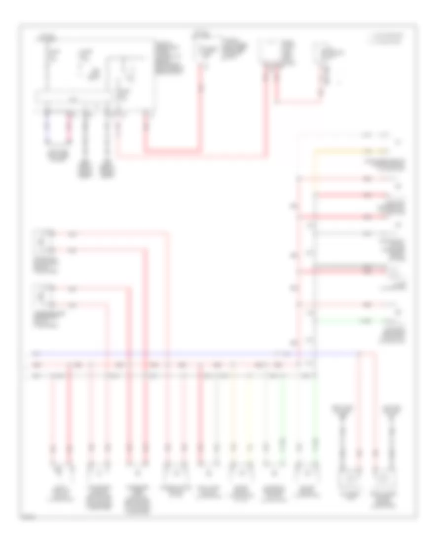
GROUND DISTRIBUTION
Ground Distribution Wiring Diagram for Infiniti FX50 2013
List of elements for Ground Distribution Wiring Diagram for Infiniti FX50 2013:
- & can gateway
- A/t assembly
- Abs actuator & electric unit (control unit)
- B202 (right kick panel)
- B224 (right "c" pillar)
- B24 (left "c" pillar)
- B61 (left side of luggage compt)
- B62 (left rear of luggage compt)
- B63 (behind rear seat)
- B7 (left kick panel)
- Back door opener switch & back door opener request switch
- Bose amplifier, woofer, woofer shield, bose amplifier shield, av control unit shield, e-sus control unit, e-sus control unit shield, ras control unit & ras motor relay
- Brake booster control unit, brake booster control unit shield, pre-crash seat belt control unit (passenger side), right rear power window switch, luggage room power socket, icc sensor integrated unit shield, tel adapter unit (w/o navigation), automatic back door control unit shield (w/ active afs) & automatic back door control unit (if equipped)
- Cooling fan control module (3.7l), brake fluid level switch, hood switch, icc brake hold relay, accelerator pedal actuator, cooling fan control module (5.0l), ipdm e/r (intelligent power distribution module engine room) (cpu), icc sensor integrated unit, left headlamp (low), cooling fan relay 2 (5.0l), horn (high/low), left front combination lamp, washer level switch, right front combination lamp, right front fog lamp & front wiper motor
- D103 (center rear of roof)
- D124 (top of left "c" pillar)
- E22 (right side of engine compt)
- E43 (left rear of engine compt)
- E46 (left rear of engine compt)
- F33 (3.7l: right front of engine) (5.0l: left front of engine)
- F34 (3.7l: right front of engine) (5.0l: left front of engine)
- High mounted stop lamp, automatic back door control unit shield (w/ automatic back door), back door lock assembly (back door switch), automatic back door close switch (w/ automatic back door), fuel level sensor unit & fuel pump (3.7l), fuel level sensor unit & fuel pump (main) shield (5.0l), fuel pump control module (5.0l), pre-crash seat belt control unit (driver side), left license plate lamp, right license plate lamp, left backup lamp & right backup lamp
- Icc sensor integrated unit shield, brake booster control unit shield, seat belt buckle switch (passenger side), front seat (passenger side), occupant detection system control unit, pre-crash seat belt control unit (passenger side), brake booster shield, right rear combination lamp & automatic back door control unit shield (w/ active afs)
- Ignition coils 7 & 8 (5.0l), ignition coils 1, 2, 3, 4, 5 & 6 & condensor
- Lane departure warning buzzer, paddle shifter (shift-down) (if equipped), paddle shifter (shift-up) (if equipped), unified meter & a/c amplifier, combination meter, steering angle sensor, fcw & ldw switch, vdc off switch, data link connector, mode select switch (e-sus mode select), low tire pressure warning control unit, yaw rate/side g sensor, power steering control unit, power steering solenoid valve, front passenger air bag off indicator, fuse block (j/b) (blower relay, ignition relay, accessory relay), seat memory switch, blower motor, ionizer, left front outside handle (request switch), door mirror remote control switch, front door lock assembly (driver side) (unlock sensor, door key cylinder switch), power window main switch, sunroof switch, combination switch, front power socket (ashtray illumination), door mirror (driver side) (door mirror defogger), console power socket, rear power socket, front power socket, accessory relay 2, warning systems switch, automatic back door control unit shield (if equipped), circuit breaker shield (w/ automatic back door), left air mix door motor, right air mix door motor, iba off switch, intake door motor & mode door motor
- Left headlamp swivel actuator shield, afs control unit, right headlamp swivel actuator shield, left air mix door motor, right air mix door motor, heated seat switch (driver side), heated seat switch (passenger side), heated seat relay, intake door motor, mode door motor, front display unit, snow mode switch, awd control unit, vdc off switch, av control unit, clock, a/t shift selector, sonar control unit (w/navigation), sonar control unit shield (w/ navigation), iba off switch, unified meter & a/c amplifier, fcw & ldw switch, lane camera unit, lane departure warning buzzer, data link connector, mode select switch (e-sus mode select), low tire pressure warning control unit, air bag diagnosis sensor unit, ionizer, fuse block (j/b) (blower relay, ignition relay, accessory relay), climate controlled seat relay, climate controlled seat switch (driver side), tilt & telescopic switch, push-button ignition switch (push switch), auto anti-dazzling inside mirror (compass, integrated homelink transmitter), roof module, rain sensor, climate controlled seat switch (passenger side), multi-function switch (hazard switch), accessory relay 2, can gateway, door mirror remote control switch, warning systems switch, automatic back door switch (w/ automatic back door), automatic back door main switch (w/ automatic back door) & automatic drive positioner control unit
- Left headlamp swivel actuator shield, right headlamp swivel actuator shield, manifold absolute pressure (map) sensor shield, air fuel ratio (a/f) sensor 1 (bank 1) shield, air fuel ratio (a/f) sensor 1 (bank 2) shield, electric throttle control actuator (bank 1) shield, electric throttle control actuator (bank 2) shield, fcw/ldw switch, clock, bcm, ecm, lane camera unit, snow mode switch, accelerator pedal position sensor shield, a/t shift selector, awd control unit, climate controlled seat relay, climate controlled seat switch (driver side), climate controlled seat control unit (driver side), climate controlled seat control unit (passenger side), key slot, tilt & telescopic switch, right front outside handle (request switch), push-button ignition switch (push switch), auto anti-dazzling inside mirror (compass, integrated homelink transmitter), front power window switch (passenger side) (w/o automatic back door), sunroof motor assembly shield, afs control unit, total illumination control unit, roof module, front seat (passenger side), heated seat switch (passenger side), heated seat switch (driver side), heated seat relay, glove box lamp, rain sensor, door mirror (passenger side) (door mirror defogger), climate controlled seat switch (passenger side), automatic back door switch (w/ automatic back door), automatic back door main switch (w/ automatic back door)
- Left rear shock absorber actuator shield & right rear shock absorber actuator shield
- M11 (left end of dash)
- M55 (left side of dash)
- M95 (right side of dash)
- Ras control unit, left rear power window switch & automatic back door warning buzzer (w/ auto- matic back door)
- Rear window defogger
- Seat belt buckle switch (driver side), front seat (driver side), around view monitor control unit, left rear combination lamp, around view monitor control unit (w/ navigation) & rear wiper motor
- Vvel control shaft position sensor (bank 1) shield, vvel actutor motor (bank 2) shield, vvel actotor motor (bank 1) shield, vvel control shaft position sensor (bank 2) shield, ipdm e/r (intelligent power distrubution module engine room) (ignition relay, front wiper relay, fuel pump relay, a/c relay, cpu), ecm, cooling fan control module 2 (5.0l), vvel control module, right headlamp (low), left front fog lamp, automatic back door control unit shield & circuit breaker shield (w/ automatic back door)
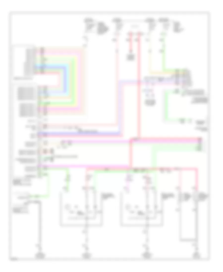
HEADLIGHTS
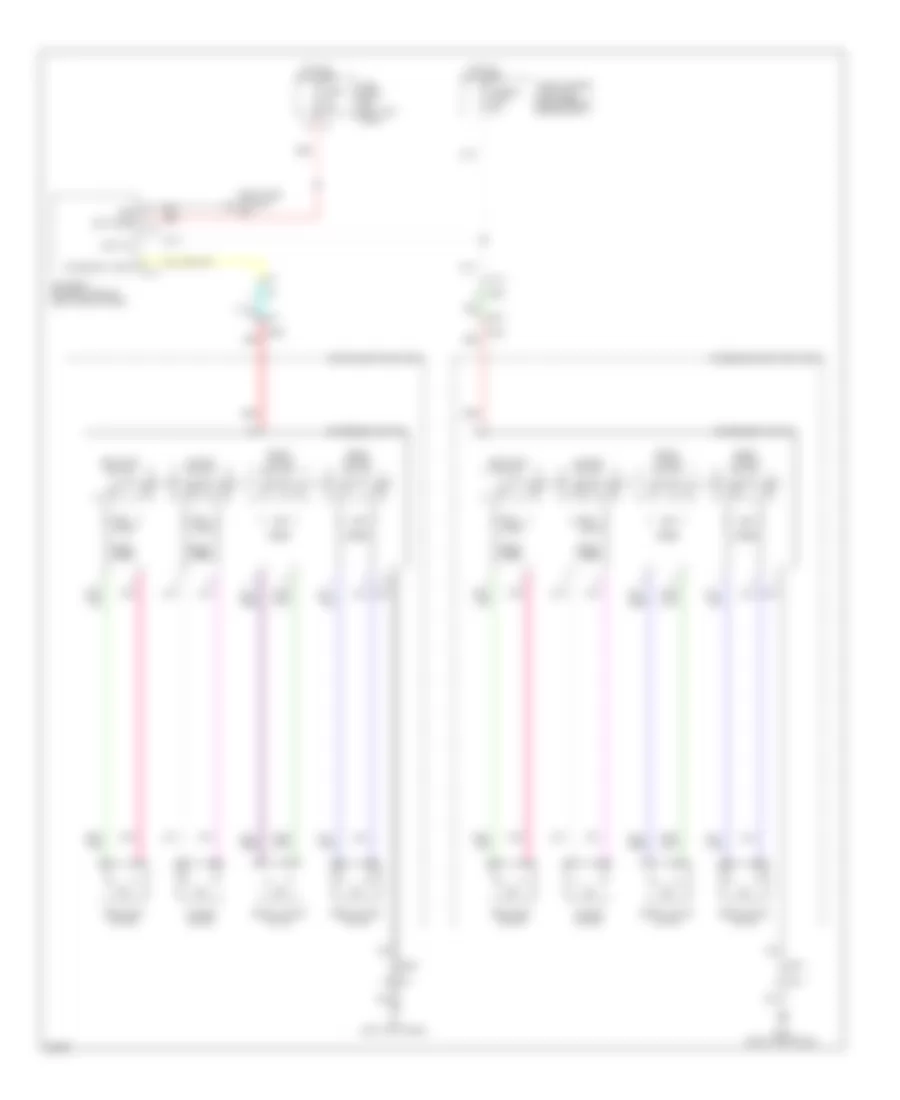
Adaptive Front Lighting Wiring Diagram for Infiniti FX50 2013
List of elements for Adaptive Front Lighting Wiring Diagram for Infiniti FX50 2013:
- (left end of dash) m11
- (left headlamp assembly)
- (left rear of engine compt) e46
- (left side of dash) m55
- (on steering column) steering angle sensor
- Acc
- Afs control unit (left end of dash)
- Amds-l
- Amds-r
- Amp-meter
- Amp-meter (afs off ind)
- Amplifier
- Batt
- Can-h
- Can-l
- Combination meter
- Computer data lines system
- Cpu
- E103
- E123
- Fuse 10a
- Fuse block (j/b) (left kick panel)
- Gnd
- Height sensor
- Hot at all times
- Hot in on or acc
- Hot in on or start
- Hs-r
- Hsg-r
- Hsv-r
- Ign
- Ipdm e/r (intelligent power distribution module engine) (right rear of engine compt)
- Left front combination lamp (headlamp aiming motor)
- Left headlamp swivel actuator
- M10
- M66
- M67
- M95 (right side of dash)
- Meter-amp
- Nca
- Pnk
- Ps-l
- Ps-r
- Psg-l
- Psg-r
- Psv-l
- Psv-r
- Red
- Right front combination lamp (headlamp aiming motor)
- Right headlamp swivel actuator (right headlamp assembly)
- Shield
- Sml-1 (+)
- Sml-1 (-)
- Sml-2 (+)
- Sml-2 (-)
- Smr-1 (+)
- Smr-1 (-)
- Smr-2 (+)
- Smr-2 (-)
- Tan
- Unified meter & a/c amplifier (center of dash)
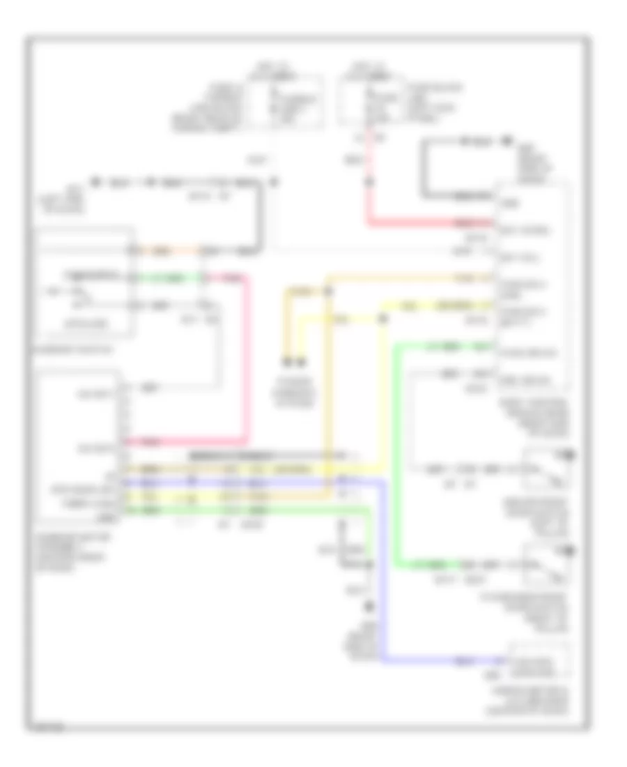
Headlamps Wiring Diagram (1 of 2) for Infiniti FX50 2013
List of elements for Headlamps Wiring Diagram (1 of 2) for Infiniti FX50 2013:
- (left side of dash) m55
- Amp-meter
- Bat
- Bat (f/l)
- Bat (fuse)
- Bcm (body control module) (right end of dash)
- Can-h
- Can-l
- Combination meter
- Combination switch
- Drv door sw
- E106 m6
- Fuse & fusible link block (right rear of engine compt)
- Fuse 10 10a
- Fuse 11 10a
- Fuse 3 10a
- Fuse block (j/b) (left kick panel)
- Fusible link l 40a
- Gnd
- High beam ind
- Hot at all times
- Hot in on or start
- Ign
- Input 1
- Input 2
- Input 3
- Input 4
- Input 5
- Interior lights system
- M118
- M119
- M121
- M122
- M123
- M66
- M67
- M95 (right side of dash)
- Meter-amp
- Optical sensor
- Output
- Output 1
- Output 2
- Output 3
- Output 4
- Output 5
- Park brk sig
- Parking brake sw
- Parking brake switch (base of parking brake assembly)
- Pass door sw
- Pnk
- Power
- Rear lh door sw
- Rear rh door sw
- Red
- Sensor gnd
- Sensor pwr
- Tan
- Unified meter & a/c amplifier (center of dash)
Headlamps Wiring Diagram (2 of 2) for Infiniti FX50 2013
List of elements for Headlamps Wiring Diagram (2 of 2) for Infiniti FX50 2013:
- Computer data lines system
- Cpu
- E151 e66
- E22 (right side of engine compt)
- E46 (left rear of engine compt)
- E66 e151
- Front fog lamp relay
- Fuse 10a
- Fuse 15a
- Fusible link f 60a
- Fusible link holder (right rear of engine compt)
- Headlamp hi beam
- Headlamp high relay
- Headlamp low relay
- Hid cont
- Hot at all times
- Hot in on or start
- Ipdm e/r (intelligent power distribution module engine room) (right rear of engine compt)
- Left front combination lamp
- Left front fog lamp
- Left headlamp low beam
- Pnk
- Red
- Right front combination lamp
- Right front fog lamp
- Right headlamp low beam
- W/ navigation
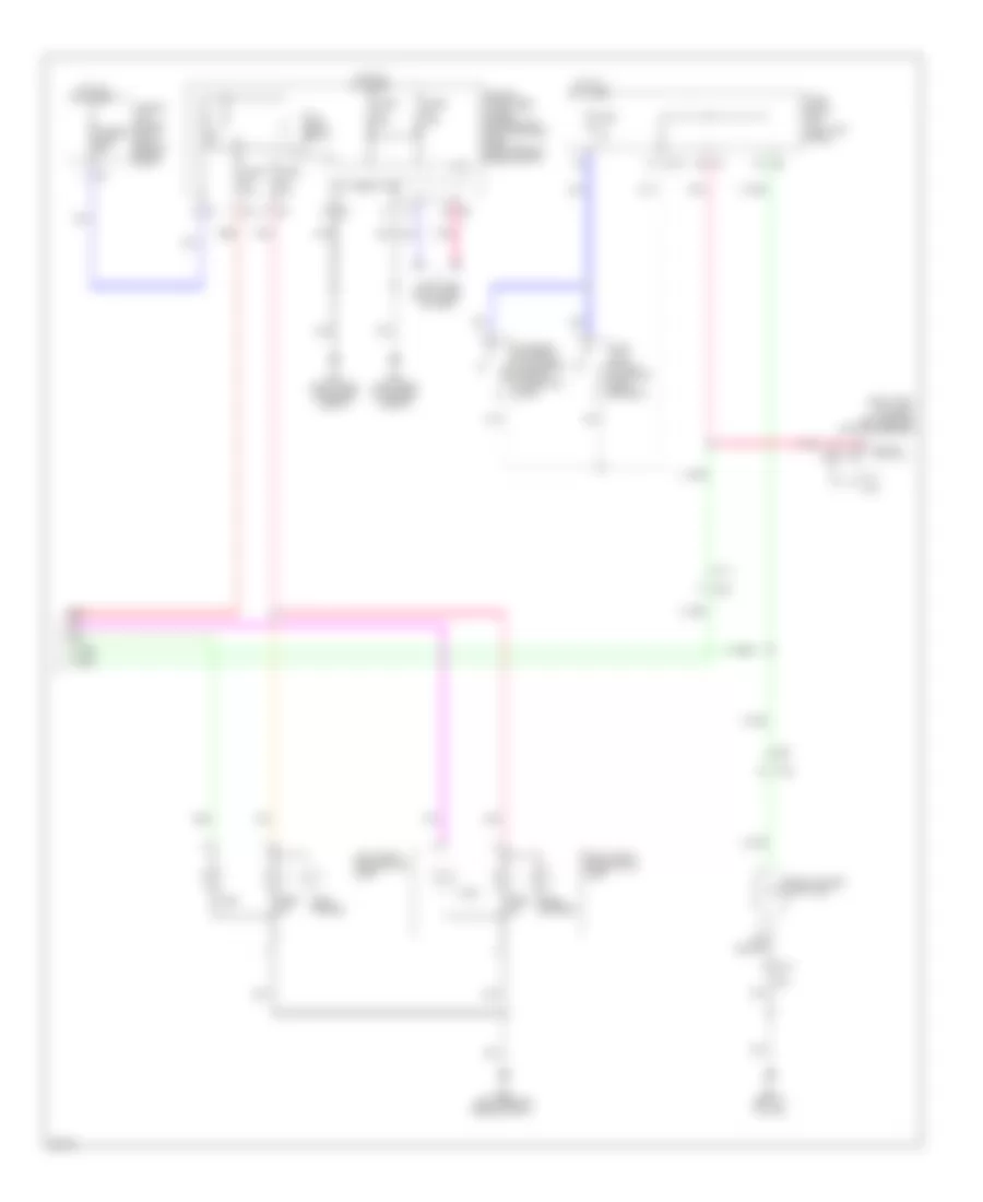
HORN
Horn Wiring Diagram for Infiniti FX50 2013
List of elements for Horn Wiring Diagram for Infiniti FX50 2013:
- Combination switch (spiral cable)
- Computer data lines system
- Cpu
- E106
- E22 (right side of engine compt)
- E46 (left rear of engine compt)
- E61
- E62
- E69
- E70
- Fuse & fusible link block (right rear of engine compt)
- Fuse 10a
- Fuse 15a
- High horn (behind left side of front grille)
- Horn relay 1 (in fuse & fusible link block)
- Horn relay 2 (in fuse & fusible link block)
- Horn switch
- Hot at all times
- Hot in on or start
- Ipdm e/r (intelligent power distribution module engine room) (right rear of engine compt)
- Low horn (behind right side of front grille)
- M303
- M36
- Pnk
INSTRUMENT CLUSTER
Instrument Cluster Wiring Diagram for Infiniti FX50 2013
List of elements for Instrument Cluster Wiring Diagram for Infiniti FX50 2013:
- (in fuel tank) fuel level sensor unit & fuel pump (main)
- (left end of dash) m11
- 12c
- 3.7l
- 5.0l
- Acc
- Air bag
- Alternator
- Amb sens
- Amb sens gnd
- Ambient sensor (behind center of front grille)
- Amp-lcd
- Amp-meter
- Anti-theft system
- Auto anti-dazzling inside mirror (compass)
- Bat
- Batt
- Brake fluid level switch (in brake fluid reservoir)
- Brk fluid sw
- Brk fluid sw driver seat belt buckle sw
- Can-h
- Can-l
- Clock
- Combination meter
- Computer data lines system
- Cpu
- E106
- E46 (left rear of engine compt)
- Enter
- Enter sw
- F10
- Fuel level sensor unit (sub)
- Fuel lvl gnd
- Fuel lvl sens
- Fuse 10a
- Fuse block (j/b) (left kick panel)
- Gnd
- Hot at all times
- Hot in on or acc
- Hot in on or start
- Ign
- Ill
- Ill (+)
- Ill (-)
- Ill con out
- Ill ctrl sw (+)
- Ill ctrl sw (-)
- Illumination control switch
- Interior lights system
- Ipdm e/r (intelligent power distribution module engine room) (right rear of engine compt)
- Lcd-amp
- M106
- M110
- M55 (left side of dash)
- M66
- M67
- M95 (right side of dash)
- Meter control switch
- Meter ctrl sw gnd
- Meter-amp
- Oil pressure switch
- Park brk sw
- Parking brake switch (base of parking brake assembly)
- Pnk
- Prk brake sw
- Red
- Seat belt
- Security
- Select
- Select sw
- Spd (8-pulse)
- Starting/charging system
- Tan
- Trip a/b reset sw
- Trip a/b reset switch
- Trip computer switch
- Unified meter & a/c amplifier (center of dash)
- Warning systems
- Washer lvl sw
- Wiper/washer system
INTERIOR LIGHTS
Courtesy Lamps Wiring Diagram (1 of 4) for Infiniti FX50 2013
List of elements for Courtesy Lamps Wiring Diagram (1 of 4) for Infiniti FX50 2013:
- Acc sig
- Accessory relay
- All on map lp sw
- Ambiance lp
- B18 d51
- B218 d71
- Bat
- Bat pwr sply
- Bat saver sig
- Computer data lines system
- Ddl2
- Dr door sw
- Dr map lp
- Dr map lp sw
- Dr sw (as)
- Dr sw (rl)
- Driver door mirror (front of driver's door)
- Driver side foot lamp
- E103
- Fr armrest lh
- Fr armrest rh
- Fuse 10a
- Fuse block (j/b) (left kick panel)
- Gnd
- Hot at all times
- Hspl ill
- Hspl pwr sply 1
- Hspl pwr sply 2
- Hspl pwr sply 3
- Ign sig
- Ill cont in
- Instrument illumination circuit
- Key slot
- Key sw sig
- Left front door armrest mood lamp
- Left rear door armrest mood lamp
- Lh foot lp
- Lh personal lp
- Lh puddle lp
- M11 (left end of dash)
- M117 b201
- M124 d31
- M5 d1
- M7 b1
- M95 (right side of dash)
- Map lp (as)
- Passenger door mirror (front of front passenger's door)
- Passenger side foot lamp
- Pnk
- Puddle lamp
- Push eng st sw led
- Red
- Rh foot lp
- Rh personal lp
- Rh puddle lp
- Right front door armrest mood lamp
- Right rear door armrest mood lamp
- Room lp timer
- Rr armrest lh
- Rr armrest rh
- Rr dr sw
- Tail lp sig
- Tan
- Total illumination control unit (right side of dash)
Courtesy Lamps Wiring Diagram (2 of 4) for Infiniti FX50 2013
List of elements for Courtesy Lamps Wiring Diagram (2 of 4) for Infiniti FX50 2013:
- All on
- Center console indirect illumination
- Computer data lines system
- Cpu
- Door
- E106
- E22 (right side of engine compt)
- E46 (left rear of engine compt)
- Fuse 10a
- Fusible link f 60a
- Fusible link holder (right rear of engine compt)
- Hot at all times
- Ignition relay
- Ipdm e/r (intelligent power distribution module engine room) (right rear of engine compt)
- Left
- Left push switch
- Left vanity mirror lamp
- M106
- M106 r1
- M55 (left side of dash)
- Main switch
- Map lamp
- Off
- Personal lamp
- Pnk
- R11
- R2 r11
- Red
- Right
- Right push switch
- Right vanity mirror lamp
- Roof module
- Tail lamp relay
- Tan
Courtesy Lamps Wiring Diagram (3 of 4) for Infiniti FX50 2013
List of elements for Courtesy Lamps Wiring Diagram (3 of 4) for Infiniti FX50 2013:
- (lower right side of back door) outside key antenna (back door)
- (rear of driver's door) (driver side) front door lock assembly
- B1 m7
- Batt
- Between full stroke & n
- D102 b28
- D31 m124
- Door lock & unlock switch
- Door locks system
- Full stroke
- Gnd
- Illumination
- Key cylinder switch
- Left front outside handle (outside key antenna) (integral to left front door handle assembly)
- Lock
- M11 (left end of dash)
- M124 d31
- M55 (left side of dash)
- M95 (right side of dash)
- Passenger side front power window switch
- Pnk
- Power window main switch
- Push switch
- Push-button ignition switch
- Red
- Remote keyless entry receiver (right end of dash)
- Right front outside handle (outside key antenna) (integral to right front door handle assembly)
- Sig out
- Tan
- Unlock
Courtesy Lamps Wiring Diagram (4 of 4) for Infiniti FX50 2013
List of elements for Courtesy Lamps Wiring Diagram (4 of 4) for Infiniti FX50 2013:
- Acc relay ctrl
- B18
- B201
- B218
- B24 (left "c" pillar)
- B241
- B28
- B67
- B67 b241
- Back ant+
- Back ant-
- Back door lock assembly (back door switch) (lower center of back door)
- Back door opener request switch
- Back dr opener sw
- Back dr sw
- Bat (f/l)
- Bat (fuse)
- Bcm (body control module) (right end of dash)
- Can-h
- Can-l
- Computer data lines system
- D102
- D31
- D51
- D71
- Diode (right side of dash)
- Door
- Driver front door switch (left "b" pillar)
- Driver side step lamp
- Drv dr ant+
- Drv dr ant-
- Drv dr request sw
- Drv dr sw
- Fuse & fusible link block (right rear of engine compt)
- Fusible link l 40a
- Gnd
- Hot at all times
- Ign f/b
- Int room lp
- Key slot sw
- Keyless entry sig
- Left front outside handle (request switch)
- Left rear door switch (left "c" pillar)
- Left rear step lamp
- Lh rear dr sw
- Luggage room lamp (back door side)
- Luggage room lamp (luggage side)
- M11 (left end of dash)
- M117
- M118
- M119
- M121
- M122
- M123
- M124
- M95 (right side of dash)
- Off
- Pass dr ant+
- Pass dr ant-
- Pass dr request sw
- Pass dr sw
- Passenger front door switch (right "b" pillar)
- Passenger side step lamp
- Pnk
- Push sw
- Pwr wdw sw comm
- Red
- Rh rear dr sw
- Right front outside handle (request switch)
- Right rear door switch (right "c" pillar)
- Right rear step lamp
- Room lp timer
- Sensor gnd
- Step lp out
- Tan
Instrument Illumination Wiring Diagram (1 of 2) for Infiniti FX50 2013
List of elements for Instrument Illumination Wiring Diagram (1 of 2) for Infiniti FX50 2013:
- (left end of dash) m11
- 12c
- A/t shift selector (illumination)
- Ambiance lp
- Bat (f/l)
- Bat (fuse)
- Bcm (body control module) (right end of dash)
- Can-h
- Can-l
- Combi sw input 1
- Combi sw input 2
- Combi sw input 3
- Combi sw input 4
- Combi sw input 5
- Combi sw output 1
- Combi sw output 2
- Combi sw output 3
- Combi sw output 4
- Combi sw output 5
- Combination meter
- Combination switch
- Combination switch (spiral cable)
- Computer data lines system
- Dr door sw
- Driver front door switch (left "b" pillar)
- Fuse & fusible link block (right rear of engine compt)
- Fuse 10a
- Fuse block (j/b) (left kick panel)
- Fusible link l 40a
- Gnd
- Hot at all times
- Hot in on or start
- Hspl illu
- Hspl pwr sply 1
- Hspl pwr sply 3
- Ill
- Ill cont in
- Illum
- Illumination control switch
- Input 1
- Input 2
- Input 3
- Input 4
- Input 5
- M106
- M118
- M119
- M122
- M123
- M303
- M35
- M36
- M67
- M95 (right side of dash)
- Map lamp (center control indirect illumination)
- Meter control switch
- Meter illum ind
- Output 1
- Output 2
- Output 3
- Output 4
- Output 5
- Pnk
- Push-button ignition switch
- R11
- Red
- Roof module
- Selector lever position indicator
- Shift position switch
- St sw led
- Steering switch (illumination)
- Tail lp sig
- Tan
- Total illumination control unit (right side of dash)
- Trip computer switch
- Unified meter & a/c amplifier (center of dash)
- Unified meter control unit
Instrument Illumination Wiring Diagram (2 of 2) for Infiniti FX50 2013
List of elements for Instrument Illumination Wiring Diagram (2 of 2) for Infiniti FX50 2013:
- (left end of dash) m11
- (right side of dash)
- Automatic back door main switch (illumination)
- Automatic back door switch (illumination)
- Av control unit
- Clock (illumination)
- Computer data lines system
- Cont ill
- Cpu
- Door mirror remote control switch (illumination)
- Driver side climate controlled seat switch (illumination) (if equipped)
- Driver side heated seat switch (if equipped)
- E103
- E22 (right side of engine compt)
- E46 (left rear of engine compt)
- Front power socket (ashtray illumination)
- Fuse 10a
- Fuse 15a
- Fuse block (j/b) (left kick panel) m2
- Fusible link f 60a
- Fusible link holder (right rear of engine compt)
- Glove box lamp
- Headlamp aiming switch (illumination)
- Hot at all times
- Iba off switch (illumination) (w/ icc)
- Ill
- Ill(+)
- Ill(-)
- Illum
- Ipdm e/r (intelligent power distribution module engine room) (right rear of engine compt)
- M201
- M210
- M95
- Mode select switch (e-sus mode select) (w/ ras)
- Multi- function switch (illumination)
- Passenger side climate controlled seat switch (illumination) (if equipped)
- Passenger side heated seat switch (if equipped)
- Pnk
- Red
- Snow mode switch (illumination)
- Tail lamp relay
- Tan
- Vdc off switch (illumination)
- W/ navigation
- W/o navigation
- Warning system switch (w/ icc)
MEMORY SYSTEMS
Memory Systems Wiring Diagram (1 of 4) for Infiniti FX50 2013
List of elements for Memory Systems Wiring Diagram (1 of 4) for Infiniti FX50 2013:
- (left center of dash) automatic drive positioner control unit
- Address1
- Address2
- Backward
- Bat
- Bat (c/b)
- Bat (fuse)
- Camera
- Defogger system
- Diode
- Down
- Driver side door mirror (front of driver's door)
- Forward
- Fuse 10a
- Fuse block (j/b) (left kick panel)
- Gnd
- Gnd (power)
- Gnd (sens)
- Gnd (signal)
- Hot at all times
- Hot in on or acc
- Ind1
- Ind2
- Interior lights system
- Key slot
- Key sw
- M51
- M52
- M55 (left side of dash)
- M95 (right side of dash)
- Mirror (left)
- Mirror mtr (horz)
- Mirror mtr (left horz)
- Mirror mtr (left ver)
- Mirror mtr (right)
- Mirror mtr (vertical)
- Mirror select sw
- Mirror sens (left)
- Mirror sens (right)
- Mirror sw (down)
- Mirror sw (left)
- Mirror sw (right)
- Mirror sw (up)
- Navigation system
- Nca
- Pnk
- Red
- Rh mirror select sw
- Rx (uart)
- Set sw
- Tan
- Teles- copic switch
- Telescopic motor
- Telescopic mtr (back)
- Telescopic mtr (fwd)
- Telescopic sens
- Telescopic sensor
- Telescopic sw (back)
- Telescopic sw (fwd)
- Tilt & telescopic motor
- Tilt & telescopic sensor
- Tilt & telescopic switch
- Tilt motor
- Tilt mtr (dn)
- Tilt mtr (up)
- Tilt sens
- Tilt sensor
- Tilt sw (down)
- Tilt sw (up)
- Tilt switch
- Tx (uart)
Memory Systems Wiring Diagram (2 of 4) for Infiniti FX50 2013
List of elements for Memory Systems Wiring Diagram (2 of 4) for Infiniti FX50 2013:
- B11
- B460
- B7 (left kick panel)
- Camera
- Circuit breaker
- Cushion side deflate solenoid
- Cushion side inflate solenoid
- D31
- Deflate cushion side
- Deflate seat back side
- Defogger system
- Driver side front seat
- Inflate
- Interior lights system
- M124
- Navigation system
- Nca
- Passenger side door mirror (front of front passenger's door)
- Pnk
- Pump
- Pump relay
- Red
- Seat back side deflate solenoid
- Seat back side inflate solenoid
- Side support switch
- Side support unit
- Tan
Memory Systems Wiring Diagram (3 of 4) for Infiniti FX50 2013
List of elements for Memory Systems Wiring Diagram (3 of 4) for Infiniti FX50 2013:
- A/t shift selector (detention switch)
- B11
- B460
- B7 (left kick panel)
- Back- ward
- Backward
- Change over switch
- Close
- Door mirror remote control switch
- Driver side front seat
- For- ward
- Forward
- Ind 1 memory
- Interior lights system
- Left
- Lumbar support
- M11 (left end of dash)
- Memory 1 switch
- Memory 2 switch
- Memory ind 2
- Mirror switch
- Motor
- Off
- Open
- Open/close switch
- Pnk
- Red
- Right
- Seat memory switch
- Set switch
- Switch
- Tan
Memory Systems Wiring Diagram (4 of 4) for Infiniti FX50 2013
List of elements for Memory Systems Wiring Diagram (4 of 4) for Infiniti FX50 2013:
- (left "b" pillar) driver side front door switch
- (right side of dash) m95
- A/t device
- B11
- B11 b460
- B14
- B14 m144
- B451
- B452
- B460
- B460 b11
- B7 (left kick panel)
- Back
- Backward
- Bat (f/l)
- Bat (fuse)
- Body control module (bcm) (right end of dash)
- Can-h
- Can-l
- Circuit breaker (center of dash)
- Computer data lines system
- Door sw (dr)
- Down
- Driver seat control unit
- Driver side front seat
- Forward
- Front lifting motor
- Front lifting sensor
- Front lifting switch
- Fuse & fusible link block (right rear of engine compt)
- Fuse 10a
- Fuse block (j/b) (left kick panel)
- Fusible link l 40a
- Fwd
- Gnd
- Hot at all times
- Key sw
- M118
- M119
- M122
- M123
- M144
- M144 b14
- M7 b1
- Pnk
- Power seat switch
- Rear lifting motor
- Rear lifting sensor
- Rear lifting switch
- Reclining motor
- Reclining sensor
- Reclining switch
- Red
- Shift p
- Sliding motor
- Sliding sensor
- Sliding switch
- W/ side support
- W/o side support
NAVIGATION
Lane Departure Warning Wiring Diagram for Infiniti FX50 2013
List of elements for Lane Departure Warning Wiring Diagram for Infiniti FX50 2013:
- Buzzer output
- Can-h
- Can-l
- Combination meter
- Comm sig
- Computer data lines system
- Fcw & ldw on ind
- Fuse 10a
- Fuse block (j/b) (left kick panel)
- Gnd
- Hot in on or start
- Ign
- Ill
- Ind
- Interior lights system
- Lane camera unit (center front of roof)
- Lane departure warning buzzer (lower center of dash)
- Ldp
- Ldw sw input
- M11 (left end of dash)
- M110
- M55 (left side of dash)
- M66
- M67
- M95 (right side of dash)
- Off
- Pnk
- Red
- Unified meter & a/c amplifier (center of dash)
- Warning systems switch
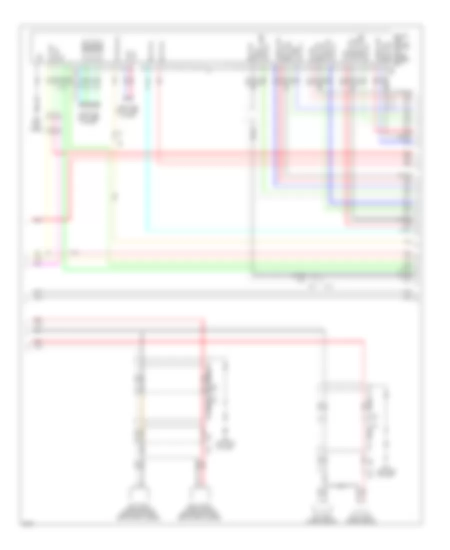
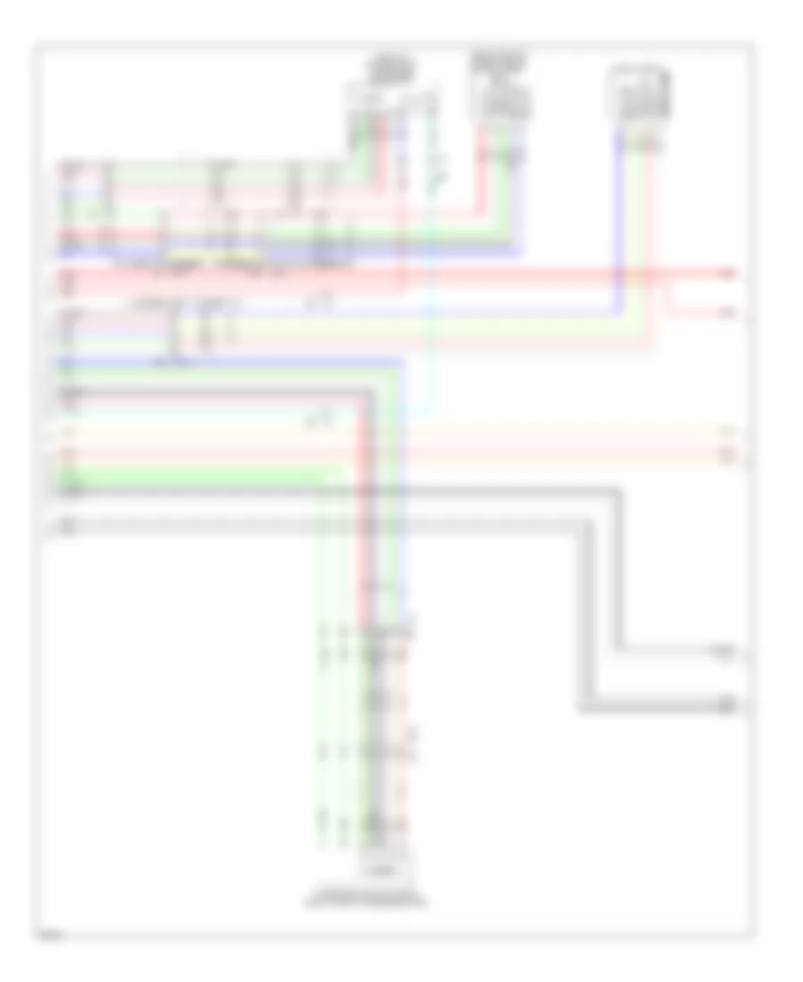
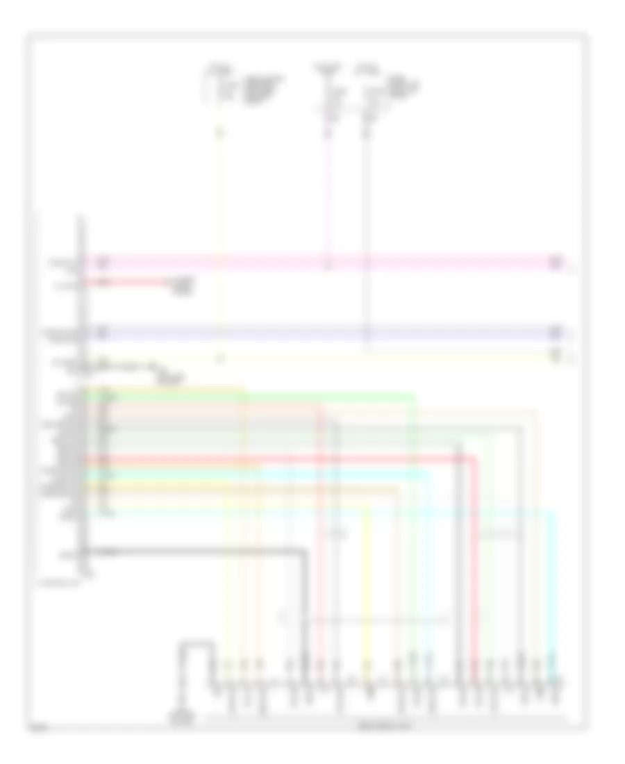
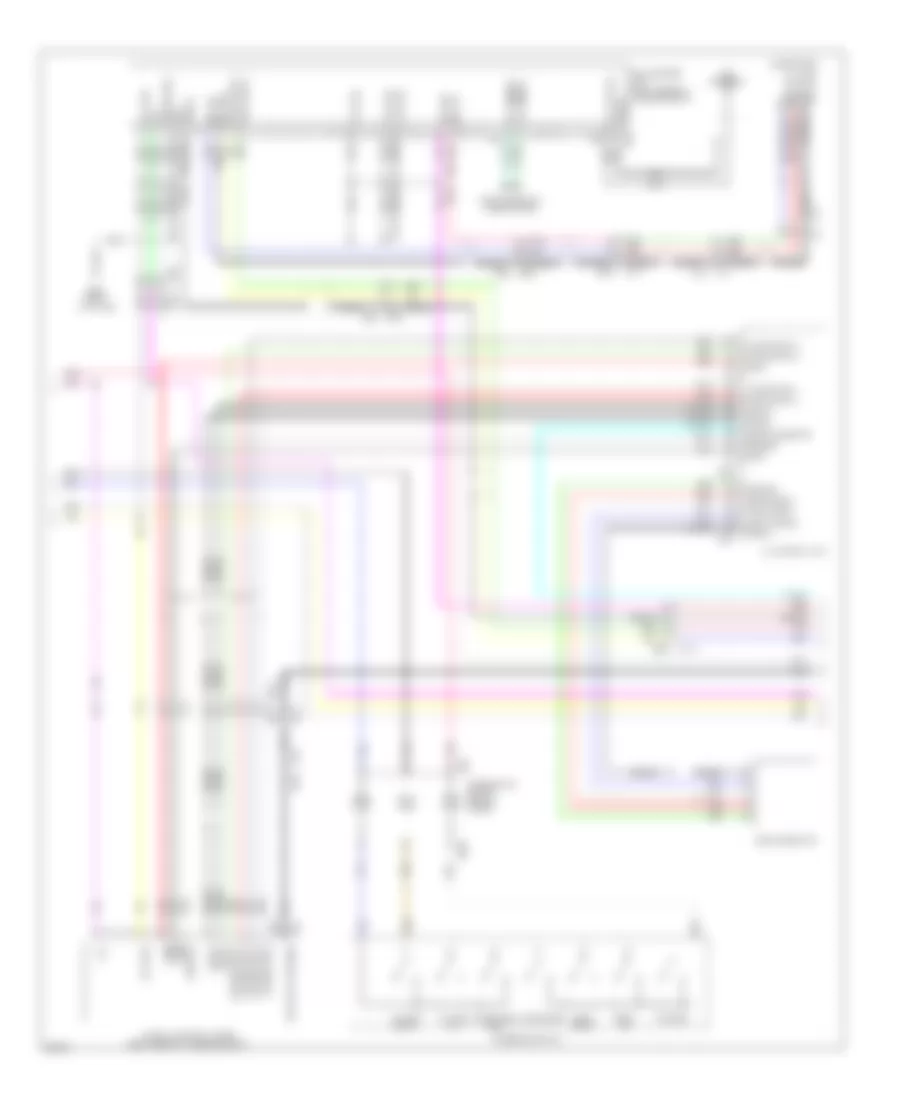
Navigation Wiring Diagram (1 of 6) for Infiniti FX50 2013
List of elements for Navigation Wiring Diagram (1 of 6) for Infiniti FX50 2013:
- (left rear of luggage compt) b62
- 12g
- Acc
- Amp on sig
- Av comm (h)
- Av comm (l)
- Av control unit
- Back
- Battery
- Can-h
- Can-l
- Change sig
- Combination switch (spiral cable)
- Computer data lines system
- Eject sig
- Enter
- Fuse & fusible link block (right rear of engine compt)
- Fuse 10a
- Fuse 15a
- Fuse 20a
- Fuse block (j/b) (left kick panel)
- Gnd
- Hot at all times
- Hot in on or acc
- Lf sound sig (+)
- Lf sound sig (-)
- Lr sound sig (+)
- Lr sound sig (-)
- M208
- M209
- M25
- M303
- M36
- M55 (left side of dash)
- M66
- M67
- Menu down
- Menu up
- Multi-function switch
- Pnk
- Red
- Rf sound sig (+)
- Rf sound sig (-)
- Rr sound sig (+)
- Rr sound sig (-)
- Shield
- Source
- Spd sig
- Steering switch
- Strg sw a
- Strg sw b
- Strg sw gnd
- Sw gnd
- Tan
- Tele- phone
- Unified meter & a/c amplifier (center of dash)
- Voice
- Volume down
- Volume up
Navigation Wiring Diagram (2 of 6) for Infiniti FX50 2013
List of elements for Navigation Wiring Diagram (2 of 6) for Infiniti FX50 2013:
- (left rear of luggage compt) b62
- (left rear of luggage compt) bose amplifier
- Am-fm main
- Amp on sig
- Antenna
- Antenna amplifier
- Antenna base
- Av control unit
- B1 m7
- B18
- B2 m25
- B201 m117
- B218
- B41
- B42
- Battery
- D1 m5
- D31 m124
- D51
- D71
- Fm sub
- Glass antenna (fm sub)
- Gnd
- Gps antenna
- Image sig (+)
- Image sig (-)
- Left front door speaker
- Left front squawker
- Left rear door speaker
- Lf sound sig (+)
- Lf sound sig (-)
- Lr sound sig (+)
- Lr sound sig (-)
- M25
- M374
- M375
- M377
- M383
- M385
- M385 m375
- M386
- M387
- M388
- M389
- M394
- M395
- M396
- M398
- Mode change sig
- Nca
- Pnk
- Red
- Rf sound sig (+)
- Rf sound sig (-)
- Right front door speaker
- Right rear door speaker
- Rod antenna (am/fm main)
- Rr sound sig (+)
- Rr sound sig (-)
- Satellite antenna
- Shield
- Sig
- Sound center (+)
- Sound center (-)
- Tan
- Woofer (+)
- Woofer (-)
Navigation Wiring Diagram (3 of 6) for Infiniti FX50 2013
List of elements for Navigation Wiring Diagram (3 of 6) for Infiniti FX50 2013:
- B241
- B62 (left rear of luggage compt)
- B67
- Battery
- Can-h
- Can-l
- Center speaker
- Computer data lines system
- Gnd
- Ign
- Left rear squawker
- Lf corner sens
- Lr corner sens
- M25
- M55 (left side of dash)
- Nca
- Pnk
- Red
- Rf corner sens
- Right front squawker
- Right rear squawker
- Rr corner sens
- Sens gnd
- Sonar control unit
- Tan
- Woofer
- Woofer (+)
- Woofer (-)
- Woofer amp
Navigation Wiring Diagram (4 of 6) for Infiniti FX50 2013
List of elements for Navigation Wiring Diagram (4 of 6) for Infiniti FX50 2013:
- (7 to 18 not used)
- (under driver's seat) around view monitor control unit
- Acc
- Av comm (h)
- Av comm (l)
- B14
- B255
- B268
- B46
- B68
- B7 (left kick panel)
- Battery
- Camera comm
- Camera gnd
- Camera sig
- Can h
- Can l
- Computer data lines system
- E123
- E153
- E65
- Gnd
- Ign sig
- Image gnd
- Image sig
- L comm
- Left front corner sensor (behind left front end of front bumper)
- Left rear corner sensor
- M10
- M144
- M55 (left side of dash)
- Millor sig
- Nca
- Nca nca
- Pnk
- Pwr sply
- R gnd
- R image gnd
- R image sig
- Red
- Reverse sig
- Rh gnd
- Right front corner sensor (behind right front end of front bumper)
- Right rear corner sensor
- Shield
- Tan
Navigation Wiring Diagram (5 of 6) for Infiniti FX50 2013
List of elements for Navigation Wiring Diagram (5 of 6) for Infiniti FX50 2013:
- (behind center of front grille) front camera
- (front of driver's door) driver side door mirror
- B28
- B5 m4
- Camera
- Camera comm
- Camera gnd
- D102
- D31
- E104
- E151
- E66
- Image gnd
- Image sig
- M124
- Nca
- Passenger side door mirror (front of front passenger's door)
- Pnk
- Pwr sply
- Rear camera
- Red
- Shield
- Tan
Navigation Wiring Diagram (6 of 6) for Infiniti FX50 2013
List of elements for Navigation Wiring Diagram (6 of 6) for Infiniti FX50 2013:
- (or red)
- 12c
- A/t assembly (on transmission)
- Acc
- Acc rly ctrl
- Accessory relay
- Av comm (h)
- Av comm (l)
- Av control unit
- Backup lamp relay (right side of dash)
- Batt
- Body control module (bcm) (right end of dash)
- Can-h
- Can-l
- Comm
- Computer data lines system
- Dr sw
- Driver front door switch (left "b" pillar)
- E106
- F103
- Front display unit
- Fuse 10a
- Fuse block (j/b) (left kick panel)
- Gnd
- Hot in on or start
- Ign sig
- Ill
- Image sig
- Image sig (+)
- Image sig (-)
- Image sig gnd
- Interior lights system
- J/c
- M110
- M116
- M122
- M123
- M195
- M210
- M212
- M397
- M55 (left side of dash)
- Mic gnd
- Mic sig
- Mic vcc
- Microphone
- Microphone shield
- Microphone sig
- Microphone vcc
- Nca
- Parking brake switch (base of parking brake assembly)
- Pnk
- Prk brake sig
- R11
- Red
- Rev rly sig
- Reverse sig
- Shield
- Sig
- Tan
- Tcm (transmission control module)
- Usb connector
- Usb d+ signal
- Usb d-signal
- Usb gnd
- V bus signal
PASSIVE RESTRAINTS
Passive Restraints Wiring Diagram for Infiniti FX50 2013
List of elements for Passive Restraints Wiring Diagram for Infiniti FX50 2013:
- 1a m1
- B1 m7
- B201
- B202 (right kick panel)
- B209
- B224 (right "c" pillar)
- B24 (left "c" pillar)
- B501
- B511
- B58
- B7 (left kick panel)
- Brake pedal stroke sensor (on brake pedal bracket)
- Buckle sw lh
- Buckle sw rh
- Can hi
- Can lo
- Computer data lines system
- Driver side front seat
- Driver side pre-crash seat belt control unit (base of left "b" pillar)
- E106
- Fuse & fusible link block (right rear of engine compt)
- Fuse 10a
- Fuse block (j/b) (left kick panel)
- Fusible link j 30a
- Fusible link k 30a
- Gnd
- Hot at all times
- Local comm 1
- Local comm 2
- M117
- Motor bat
- Motor gnd
- Out
- Out 1
- Out 2
- Passenger side front seat
- Passenger side pre-crash seat belt control unit (base of right "b" pillar)
- Pnk
- Red
- Seat belt buckle switch
- Sens gnd 1
- Sens power 1
- Sheld m6
- Shield
- Shield gnd
- Sig bat
- Sig gnd
- Tan
- Vcc
POWER DISTRIBUTION
Power Distribution Wiring Diagram (1 of 3) for Infiniti FX50 2013
List of elements for Power Distribution Wiring Diagram (1 of 3) for Infiniti FX50 2013:
- (left kick panel) fuse block (j/b)
- (option connector)
- (right side of dash) m95
- 12g
- Acc ind
- Accessory relay 2 (right side of dash)
- Anti-lock brakes system
- B201
- B224 (right "c" pillar)
- Battery
- Bcm (body control module) (right end of dash)
- Body computer system
- Body computer, interior lights & memory systems
- Body computer, memory & seats systems
- Computer data lines, transmissions & instrument cluster systems
- Cpu
- Cruise control system
- Door locks & anti-theft systems
- E101
- E103
- E106 m6
- E201
- E202
- E205
- Electronic power steering system
- Engine controls system
- Exterior lights & cruise control systems
- From fuse block j/b accessory relay (diagram 2 of 3)
- From fusible link holder fusible link p (diagram 2 of 3)
- Fuse & fusible link block (right rear of engine compt)
- Fuse (5.0l) 30a
- Fuse 10a
- Fuse 15a
- Fuse 20a
- Fusible link a 250a
- Fusible link b 100a
- Fusible link c 100a
- Fusible link d 80a
- Fusible link e 100a
- Fusible link f 60a
- Fusible link g 50a
- Fusible link h 30a
- Fusible link holder (right rear of engine compt)
- Fusible link j 30a
- Fusible link k 30a
- Fusible link l 40a
- Fusible link m 30a
- Fusible link n 50a
- Fusible link q 30a
- Horns & starting/ charging systems
- Horns system
- Instrument cluster, door locks, anti-theft, computer data lines, air conditioning, wiper/washer, warning & mirrors systems
- Interior lights system
- Ipdm e/r (intelligent power distribution module engine room) (right rear of engine compt)
- Lock ind
- Luggage room power socket
- M11 (left end of dash)
- M117
- M119
- M121
- M122
- M123
- Navigation & sound systems
- Nca
- On ind
- Passive restraints system
- Passive restraints, air conditioning,
- Pnk
- Push button ignition switch
- Push sw
- Push switch
- Red
- Seats system
- Starting/ charging system
- Tan
- To accessory relay (diagram 2 of 3)
- To fuse block (j/b) iginition relay (diagram 2 of 3)
- To fusible link holder fusible link s (diagram 2 of 3)
- To ipdm e/r fuse 50 (diagram 3 of 3)
- To ipdm e/r fuse 58 (diagram 3 of 3)
- To ipdm e/r starter relay (diagram 3 of 3)
- Transmissions & cruise control systems
- Transmissions system
- Trunk, tailgate, fuel doors system
- W/ icc
- W/ ras
Power Distribution Wiring Diagram (2 of 3) for Infiniti FX50 2013
List of elements for Power Distribution Wiring Diagram (2 of 3) for Infiniti FX50 2013:
- (right end of dash) bcm (body control module)
- (right rear of engine compt)
- 10f
- 11c
- 12c
- Acc rly
- Accessory relay
- Air conditioning system
- Bat
- Blower relay
- Blw2 rly cont
- Computer data lines system, seats, sound, navigation, warning, headlights, air conditioning, instrument cluster & mirrors systems
- Console power socket
- Cooling fans system
- E102
- E103
- E106
- Electronic suspension system
- From fuse & fusible link block fusible link h (diagram 1 of 3)
- From fuse 5 e (diagram 1 of 3)
- From fusible link holder fusible link b (diagram 1 of 3)
- Front power socket
- Fuse 10a
- Fuse 15a
- Fuse 20a
- Fuse block (j/b) (left kick panel)
- Fusible link holder
- Fusible link o 50a
- Fusible link p 50a
- Fusible link s (5.0l) 50a
- Headlights, exterior lights, cruise control, & shift interlock systems
- Ign rly (f/b)
- Ignition relay
- Interior lights system
- M11 (left end of dash)
- M119
- M122
- M6 e106
- Memory, air conditioning, interior lights, instrument cluster, mirrors, navigation & sound systems
- Navigation, exterior lights & instrument cluster systems
- Pnk
- Rear power socket
- Rear window defogger relay
- Red
- Tan
- To accessory relay 2 (diagram 1 of 3)
- To fuse & fusible link block fuse 61 (diagram 1 of 3)
- W/ras
Power Distribution Wiring Diagram (3 of 3) for Infiniti FX50 2013
List of elements for Power Distribution Wiring Diagram (3 of 3) for Infiniti FX50 2013:
- (or tan)
- (right rear of engine compt) ipdm e/r (intelligent power distribution module engine room)
- A/c relay
- Anti-lock brakes, cruise control, electronic power steering & transmissions systems
- Cooling fans system
- Cpu
- Cruise control system
- E22 (right side of engine compt)
- Ecm relay
- Engine controls system
- Exterior lights system
- From fuse & fusible link block g fusible link h (diagram 1 of 3)
- From fuse 51 (diagram 3 of 3)
- From fusible link holder a
- From fusible link holder b
- From headlamp high relay (diagram 3 of 3)
- Front fog lamp relay
- Front wiper high relay
- Front wiper relay
- Fuel pump relay
- Fuse 10a
- Fuse 15a
- Fuse 30a
- Fusible link d (diagram 1 of 3)
- Fusible link f (diagram 1 of 3)
- Head lamp high relay
- Head lamp low relay
- Ignition relay
- Interior & exterior lights system
- Interior lights & body computer systems
- Pnk
- Red
- Starter relay
- Tail-lamp relay
- Tan
- Throttle control motor relay
- To fuse 49 (diagram 3 of 3)
- To fuse 60 (diagram 3 of 3)
- Transmissions system
- Wiper/ washer system
- Wiper/washer system
POWER DOOR LOCKS
Power Door Locks Wiring Diagram (1 of 4) for Infiniti FX50 2013
List of elements for Power Door Locks Wiring Diagram (1 of 4) for Infiniti FX50 2013:
- (rear of driver's door) driver side door lock assembly
- (rear of front passenger's door) passenger side front door lock assembly
- (right end of dash) body control module (bcm)
- (right side of dash) m95
- Acc ind
- Back ant+
- Back ant-
- Back door opener sw
- Back door sw
- Bat (f/l)
- Bat (fuse)
- Between full stroke & n
- Buzzer
- Can-h
- Can-l
- Computer data lines system
- D1 m5
- D31
- Door lock & unlock switch
- Door lock actuator
- Dr door sen
- Dr lock out (all)
- Dr request sw
- Dr sw (drv)
- Dr sw (pass)
- Dr sw (rr lh)
- Dr sw (rr rh)
- Dr unlock out (drv)
- Dr unlock out (pass)
- Dr unlock out (rr)
- Drv dr ant+
- Drv dr ant-
- Exterior lights system
- Full stroke
- Fuse & fusible link block (right rear of engine compt)
- Fusible link l 40a
- Gnd
- Hot at all times
- Ign rly
- Inside key antenna (instrument center) (center of dash)
- Interior lights system
- Key cylinder switch
- Key slot ill cont
- Key slot sw
- Keyless entry sig
- Left front outside handle (request switch)
- Left front outside key antenna (integral to left front door handle assembly)
- Lf fr turn sig
- Lock
- Lock ind
- Lr turn sig
- Luggage room ant+
- Luggage room ant-
- M11 (left end of dash)
- M118
- M119
- M120
- M121
- M122
- M123
- M124
- M124 d31
- M5 d1
- Nats ant amp
- On ind
- Pass dr ant+
- Pass dr ant-
- Pass request sw
- Pnk
- Power window main switch
- Power windows system
- Push sw
- Pwr sply
- Pwr wdw sw comm
- Red
- Request sw
- Rh fr turn sig
- Right front outside key antenna (integral to right front door handle assembly)
- Room ant1+
- Room ant1-
- Room lamp timer
- Rr turn sig
- Security ind out
- Sensor gnd
- Shift n/p
- Shift p
- St relay cont
- Stop lamp sw1
- Stop lamp sw2
- Tan
- Unlock
- Unlock sensor
Power Door Locks Wiring Diagram (2 of 4) for Infiniti FX50 2013
List of elements for Power Door Locks Wiring Diagram (2 of 4) for Infiniti FX50 2013:
- (center front of luggage compt) inside key antenna (luggage room)
- (lower right side of back door) outside key antenna (back door)
- (rear of left rear door) left rear door lock assembly
- (rear of right rear door) right rear door lock assembly
- (right side of luggage compt) fuel lid lock actuator
- Acc
- B1 m7
- B18
- B201 m117
- B218
- Back door opener request switch
- Back door opener switch
- Batt
- D102 b28
- D103 (center rear of roof)
- D31
- D31 m124
- D51
- D71
- Door lock & unlock switch
- Gnd
- Ill
- Interior lights system
- Lock
- M117 b201
- M124
- M95 (right side of dash)
- Passenger side front power window switch
- Pnk
- Push switch
- Push- button ignition switch
- Red
- Remote keyless entry receiver (right end of dash)
- Right front outside handle (request switch)
- Sig out
- Tan
Power Door Locks Wiring Diagram (3 of 4) for Infiniti FX50 2013
List of elements for Power Door Locks Wiring Diagram (3 of 4) for Infiniti FX50 2013:
- (left "c" pillar) left rear door switch
- (or pnk)
- (right "c" pillar) right rear door switch
- 3.7l
- 5.0l
- A/t assembly (on transmission)
- A/t shift selector (detection switch)
- B201
- Bat
- Clock
- Computer data lines system
- Cpu
- Data
- E10
- E106
- E22 (right side of engine compt)
- E46 (left rear of engine compt)
- F10
- Fuse 15a
- Gnd
- Headlamp high relay
- Headlamp low relay
- Headlights system
- Hood switch (right front of engine compt)
- Horns system
- Hot at all times
- Ill
- Ill bat key slot
- Intelligent key warning buzzer (engine room) (right front of engine compt)
- Ipdm e/r (intelligent power distribution module engine room) (right rear of engine compt)
- Joint connector
- M117
- M6 e106
- M95 (right side of dash)
- Pnk
- Red
- Sig sw
- Starter control relay
- Starter relay
- Starting/ charging system
- Tan
- Transmission control module (tcm)
Power Door Locks Wiring Diagram (4 of 4) for Infiniti FX50 2013
List of elements for Power Door Locks Wiring Diagram (4 of 4) for Infiniti FX50 2013:
- (right "b" pillar)
- 12c
- Acc
- Amp-lcd
- Amp-meter
- B201
- B24 (left "c" pillar)
- B27
- B28
- Back door switch assembly (lower center of back door)
- Buzzer
- Can-h
- Can-l
- Combination meter
- Computer data lines system
- Cruise control system
- D101
- D102
- Driver side front door switch (left "b" pillar)
- E103
- Fuse 10a
- Fuse block (j/b) (left kick pedal)
- Gnd
- Hot at all times
- Hot in acc or on
- Hot in on or start
- Ign
- Key ind
- Lcd-amp
- M11 (left end of dash)
- M117
- M66
- M67
- Meter-amp
- Passenger side front door switch
- Pnk
- Red
- Security ind
- Stop lamp switch (on brake pedal bracket)
- Tan
- Unified meter & a/c amplifier (center of dash)
- Unified meter control unit
POWER MIRRORS
Auto Anti-dazzling Inside Mirror Wiring Diagram for Infiniti FX50 2013
List of elements for Auto Anti-dazzling Inside Mirror Wiring Diagram for Infiniti FX50 2013:
- Auto anti-dazzling inside mirror
- Bat
- Fuse 3 10a
- Fuse 6 10a
- Fuse block (j/b) (left kick panel)
- Gnd
- Hot at all times
- Hot in on or start
- Ign
- M1 2a
- M106
- M110
- M2 6b
- M95 (right side of dash)
Power Mirrors Wiring Diagram for Infiniti FX50 2013
List of elements for Power Mirrors Wiring Diagram for Infiniti FX50 2013:
- (right side of dash) diode
- Camera
- Change over switch
- Close
- Defogger system
- Door mirror remote control switch
- Down- ward
- Driver side door mirror (front of driver's door)
- Fuse 19 10a
- Fuse block (j/b) (left kick panel)
- Hot in on or acc
- Illumination
- Interior lights system
- Left- ward
- M11 (left end of dash)
- M124 d31
- M5 d1
- Mirror switch
- Navigation system
- Nca
- Off
- Open
- Open/close switch
- Passenger side door mirror (front of front passenger's door)
- Pnk
- Red
- Right- ward
- Tan
- Up- ward
POWER SEATS
Climate Control Seats Wiring Diagram for Infiniti FX50 2013
List of elements for Climate Control Seats Wiring Diagram for Infiniti FX50 2013:
- (right rear of
- 2a m1
- B1 m7
- B201
- B209
- B501
- B507
- B508
- B509
- B511
- B517
- B518
- B519
- B58
- Climate controlled seat relay (center of dash)
- Cool
- Cool ind
- Driver side climate controlled
- Driver side climate controlled seat blower motor
- Driver side climate controlled seat control unit
- Driver side front seat
- Driver side seat back thermal electric device
- Driver side seat cushion thermal electric device
- E106
- Engine compt)
- Fuse & fusible link block
- Fuse 10a
- Fuse 15a
- Fuse block (j/b) (left kick panel)
- Heat
- Heat ind
- Hot at all times
- Hot in on or start
- Illumination
- Interior lights system
- M117
- M55 (left side of dash)
- M95 (right side of dash)
- Mid
- Off
- Passenger side climate controlled
- Passenger side climate controlled seat blower motor
- Passenger side climate controlled seat control unit
- Passenger side front seat
- Passenger side seat back thermal electric device
- Passenger side seat cushion thermal electric device
- Pnk
- Red
- Seat switch
- Tan
- Ted
Heated Seats Wiring Diagram for Infiniti FX50 2013
List of elements for Heated Seats Wiring Diagram for Infiniti FX50 2013:
- (right side of dash) m95
- B201
- B201 m117
- B209
- B441 b442
- B464 b465
- B501
- B511
- B58
- Driver side front seat
- Driver side heated seat switch
- E106
- Fuse & fusible link block (right rear of engine compt)
- Fuse 3 10a
- Fuse 61 15a
- Fuse block (j/b) (left kick panel)
- Heat sensor
- Heated seat control unit
- Heated seat relay
- Heater main
- Hot at all times
- Hot in on or start
- Indicator
- Interior lights system
- M117
- M95 (right side of dash)
- Main heater
- Nca
- Passenger side front seat
- Passenger side heated seat switch
- Red
- Seat back heater
- Seat cushion heater
- Sub- heater
- Sub-heater
- Tan
Lumbar Wiring Diagram for Infiniti FX50 2013
List of elements for Lumbar Wiring Diagram for Infiniti FX50 2013:
- B11
- B460
- B7 (left kick panel)
- Back- ward
- Backward
- Bat (f/l)
- Bat (fuse)
- Bcm (body control module) (right end of dash)
- Driver side front seat
- For- ward
- Forward
- Fuse & fusible link block (right rear of engine compt)
- Fuse 10a
- Fuse block (j/b) (left kick panel)
- Fusible link l 40a
- Gnd
- Hot at all times
- Lumbar support motor
- Lumbar support switch
- M118
- M119
- M95 (right side of dash)
- Pwr window (bat)
- Red
Power Seats Wiring Diagram for Infiniti FX50 2013
List of elements for Power Seats Wiring Diagram for Infiniti FX50 2013:
- (right side of dash) m95
- B11
- B201
- B202 (right kick panel)
- B211
- B431
- B460
- B7 (left kick panel)
- Back- ward
- Bat (f/l)
- Bat (fuse)
- Bcm (body control module) (right end of dash)
- Down
- Driver side front seat
- For- ward
- Front lifting motor
- Front lifting switch
- Fuse & fusible link block (right rear of engine compt)
- Fuse 10a
- Fuse block (j/b) (left kick panel)
- Fusible link l 40a
- Gnd
- Hot at all times
- M117
- M118
- M119
- Passenger side front seat
- Pnk
- Power seat switch
- Power sply (bat)
- Rear lifting motor
- Rear lifting switch
- Reclining motor
- Reclining switch
- Red
- Sliding motor
- Sliding switch
POWER TOP/SUNROOF
Power Top/Sunroof Wiring Diagram for Infiniti FX50 2013
List of elements for Power Top/Sunroof Wiring Diagram for Infiniti FX50 2013:
- B1 m7
- B201 m117
- Bat (f/l)
- Bat (fuse)
- Body control module (bcm) (right end of dash)
- Down/open
- Driver front door switch (left "b" pillar)
- Drv dr sw
- Fuse & fusible link block (right rear of engine compt)
- Fuse 10a
- Fuse block (j/b) (left kick panel)
- Fusible link l 40a
- Gnd
- Hot at all times
- M1 7a
- M106
- M11 (left end of dash)
- M118
- M119
- M123
- M66
- M95 (right side of dash)
- Nca
- Pass dr sw
- Passenger front door switch (right "b" pillar)
- Pnk
- Power
- Pwr sply (batt)
- Pwr sply (ign)
- R2 r11
- R7 m110
- Red
- Shield
- Spd sens (2p)
- Sunroof motor assembly (center front of roof)
- Sunroof switch
- Sw bit0
- Sw bit1
- Tan
- Timer (+ign)
- Unified meter & a/c amplifier (center of dash)
- Up/close
- Veh spd (2-pulse)
- Windows system
POWER WINDOWS
Power Windows Wiring Diagram (1 of 2) for Infiniti FX50 2013
List of elements for Power Windows Wiring Diagram (1 of 2) for Infiniti FX50 2013:
- (right side of dash)
- B201
- Bat (f/l)
- Bat (fuse)
- Bcm (body control module) (right end of dash)
- Between full stroke & n
- Door locks system
- Driver door lock assembly (key cylinder switch)
- Driver front door switch (left "b" pillar)
- Driver power window motor (center of driver's door)
- Drv door sw
- Encoder
- Full stroke
- Fuse & fusible link block (right rear of engine compt)
- Fuse 10a
- Fuse block (j/b) (left kick panel)
- Fusible link l 40a
- Gnd
- Hot at all times
- Ill
- Keyless entry sig
- Keyless power sply
- Left rear
- Lock
- Lock switch
- M106
- M11 (left end of dash)
- M117
- M118
- M119
- M122
- M123
- M95
- M95 (right side of dash)
- Module
- Nca
- Pass door sw
- Passenger front door switch (right "b" pillar)
- Pnk
- Power window lock switch
- Power window main switch
- Power window sw
- Pwr sply
- Pwr sply (ign)
- Red
- Right rear
- Sens gnd
- Shield
- Sunroof motor assembly (center front of roof)
- Tan
- Timer(+ign)
- Unlock
- Unlock switch
Power Windows Wiring Diagram (2 of 2) for Infiniti FX50 2013
List of elements for Power Windows Wiring Diagram (2 of 2) for Infiniti FX50 2013:
- B18
- B201
- B218
- B224 (right "c" pillar)
- B61 (left side of luggage compt)
- D31
- D51
- D71
- Down
- Encoder
- Front passenger side power window switch
- Ill
- Left rear power window motor (center of left rear door)
- Left rear power window switch
- M117
- M124
- M124 d31
- M95 (right side of dash)
- Module
- Passenger power window motor (center of front passenger's door)
- Pnk
- Red
- Right rear power window motor (center of right rear door)
- Right rear power window switch
- Tan
RADIO
Radio Wiring Diagram, with Navigation (1 of 6) for Infiniti FX50 2013
List of elements for Radio Wiring Diagram, with Navigation (1 of 6) for Infiniti FX50 2013:
- (left rear of luggage compt) b62
- 12g
- Acc
- Amp on sig
- Av comm (h)
- Av comm (l)
- Av control unit
- Back
- Battery
- Can-h
- Can-l
- Change sig
- Combination switch (spiral cable)
- Computer data lines system
- Eject sig
- Enter
- Fuse & fusible link block (right rear of engine compt)
- Fuse 10a
- Fuse 15a
- Fuse 20a
- Fuse block (j/b) (left kick panel)
- Gnd
- Hot at all times
- Hot in on or acc
- Lf sound sig (+)
- Lf sound sig (-)
- Lr sound sig (+)
- Lr sound sig (-)
- M208
- M209
- M25
- M303
- M36
- M55 (left side of dash)
- M66
- M67
- Menu down
- Menu up
- Multi-function switch
- Pnk
- Red
- Rf sound sig (+)
- Rf sound sig (-)
- Rr sound sig (+)
- Rr sound sig (-)
- Shield
- Source
- Spd sig
- Steering switch
- Strg sw a
- Strg sw b
- Strg sw gnd
- Sw gnd
- Tan
- Tele- phone
- Unified meter & a/c amplifier (center of dash)
- Voice
- Volume down
- Volume up
Radio Wiring Diagram, with Navigation (2 of 6) for Infiniti FX50 2013
List of elements for Radio Wiring Diagram, with Navigation (2 of 6) for Infiniti FX50 2013:
- (left rear of luggage compt) b62
- (left rear of luggage compt) bose amplifier
- Am-fm main
- Amp on sig
- Antenna
- Antenna amplifier
- Antenna base
- Av control unit
- B1 m7
- B18
- B2 m25
- B201 m117
- B218
- B41
- B42
- Battery
- D1 m5
- D31 m124
- D51
- D71
- Fm sub
- Glass antenna (fm sub)
- Gnd
- Gps antenna
- Image sig (+)
- Image sig (-)
- Left front door speaker
- Left front squawker
- Left rear door speaker
- Lf sound sig (+)
- Lf sound sig (-)
- Lr sound sig (+)
- Lr sound sig (-)
- M25
- M374
- M375
- M377
- M383
- M385
- M385 m375
- M386
- M387
- M388
- M389
- M394
- M395
- M396
- M398
- Mode change sig
- Nca
- Pnk
- Red
- Rf sound sig (+)
- Rf sound sig (-)
- Right front door speaker
- Right rear door speaker
- Rod antenna (am/fm main)
- Rr sound sig (+)
- Rr sound sig (-)
- Satellite antenna
- Shield
- Sig
- Sound center (+)
- Sound center (-)
- Tan
- Woofer (+)
- Woofer (-)
Radio Wiring Diagram, with Navigation (3 of 6) for Infiniti FX50 2013
List of elements for Radio Wiring Diagram, with Navigation (3 of 6) for Infiniti FX50 2013:
- B241
- B62 (left rear of luggage compt)
- B67
- Battery
- Can-h
- Can-l
- Center speaker
- Computer data lines system
- Gnd
- Ign
- Left rear squawker
- Lf corner sens
- Lr corner sens
- M25
- M55 (left side of dash)
- Nca
- Pnk
- Red
- Rf corner sens
- Right front squawker
- Right rear squawker
- Rr corner sens
- Sens gnd
- Sonar control unit
- Tan
- Woofer
- Woofer (+)
- Woofer (-)
- Woofer amp
Radio Wiring Diagram, with Navigation (4 of 6) for Infiniti FX50 2013
List of elements for Radio Wiring Diagram, with Navigation (4 of 6) for Infiniti FX50 2013:
- (7 to 18 not used)
- Acc
- Around view monitor control unit (under driver's seat)
- Av comm (h)
- Av comm (l)
- B14
- B255
- B268
- B46
- B68
- B7 (left kick panel)
- Battery
- Camera comm
- Camera gnd
- Camera sig
- Can h
- Can l
- Computer data lines system
- E123
- E153
- E65
- Gnd
- Ign sig
- Image gnd
- Image sig
- L comm
- Left front corner sensor (behind left front end of front bumper)
- Left rear corner sensor
- M10
- M144
- M55 (left side of dash)
- Millor sig
- Nca
- Nca nca
- Pnk
- Pwr sply
- R gnd
- R image gnd
- R image sig
- Red
- Reverse sig
- Rh gnd
- Right front corner sensor (behind right front end of front bumper)
- Right rear corner sensor
- Shield
- Tan
Radio Wiring Diagram, with Navigation (5 of 6) for Infiniti FX50 2013
List of elements for Radio Wiring Diagram, with Navigation (5 of 6) for Infiniti FX50 2013:
- (behind center of front grille) front camera
- (front of driver's door) driver side door mirror
- B28
- B5 m4
- Camera
- Camera comm
- Camera gnd
- D102
- D31
- E104
- E151
- E66
- Image gnd
- Image sig
- M124
- Nca
- Passenger side door mirror (front of front passenger's door)
- Pnk
- Pwr sply
- Rear camera
- Red
- Shield
- Tan
Radio Wiring Diagram, with Navigation (6 of 6) for Infiniti FX50 2013
List of elements for Radio Wiring Diagram, with Navigation (6 of 6) for Infiniti FX50 2013:
- (or red)
- 12c
- A/t assembly (on transmission)
- Acc
- Acc rly ctrl
- Accessory relay
- Av comm (h)
- Av comm (l)
- Av control unit
- Backup lamp relay (right side of dash)
- Batt
- Body control module (bcm) (right end of dash)
- Can-h
- Can-l
- Comm
- Computer data lines system
- Dr sw
- Driver front door switch (left "b" pillar)
- E106
- F103
- Front display unit
- Fuse 10a
- Fuse block (j/b) (left kick panel)
- Gnd
- Hot in on or start
- Ign sig
- Ill
- Image sig
- Image sig (+)
- Image sig (-)
- Image sig gnd
- Interior lights system
- J/c
- M110
- M116
- M122
- M123
- M195
- M210
- M212
- M397
- M55 (left side of dash)
- Mic gnd
- Mic sig
- Mic vcc
- Microphone
- Microphone shield
- Microphone sig
- Microphone vcc
- Nca
- Parking brake switch (base of parking brake assembly)
- Pnk
- Prk brake sig
- R11
- Red
- Rev rly sig
- Reverse sig
- Shield
- Sig
- Tan
- Tcm (transmission control module)
- Usb connector
- Usb d+ signal
- Usb d-signal
- Usb gnd
- V bus signal
Radio Wiring Diagram, without Navigation (1 of 4) for Infiniti FX50 2013
List of elements for Radio Wiring Diagram, without Navigation (1 of 4) for Infiniti FX50 2013:
- 12g
- Acc
- Av control unit
- Battery
- Comm
- Front display unit
- Fuse & fusible link block (right rear of engine compt)
- Fuse 10a
- Fuse 15a
- Fuse 20a
- Fuse block (j/b) (left kick panel)
- Gnd
- Hot at all times
- Hot in acc or on
- Illum sig
- Image gnd
- Image sig
- Image sig gnd
- Interior lights system
- Inverter
- Inverter gnd
- Inverter vcc
- M201
- M202
- M55 (left side of dash)
- Pnk
- Red
- Rgb area
- Rgb area sig
- Rgb sig
- Rgb sync
- Shield
- Sig gnd
- Sig vcc
- Strg sw a
- Strg sw b
- Strg sw gnd
- Tan
Radio Wiring Diagram, without Navigation (2 of 4) for Infiniti FX50 2013
List of elements for Radio Wiring Diagram, without Navigation (2 of 4) for Infiniti FX50 2013:
- (or red)
- (right rear of luggage compt)
- Acc
- Av comm (h)
- Av comm (l)
- Av control unit
- B201
- B201 m117
- B224 (right "c" pillar)
- B236
- B243
- B481
- B482
- B491
- B492
- B496
- B66
- B87
- B88
- Battery
- Combination switch (spiral cable)
- Comm
- Computer data lines system
- Ctrl sig
- Gnd
- Ignition sig
- L sound sig (+)
- L sound sig (-)
- M110
- M117
- M206
- M207
- M303
- M36
- Menu down
- Menu up
- Mic gnd
- Mic sig
- Mic vcc
- Microphone
- Mode change sig
- Nca
- Pnk
- R sound sig (+)
- R sound sig (-)
- R11
- Red
- Request
- Satellite antenna
- Satellite radio tuner
- Shield
- Source
- Spd sig
- Steering switch
- Tel adapter unit (right rear of luggage compt)
- Tel ant sig
- Tel antenna
- Telephone
- Telephone end
- Usb connector
- Usb d+ signal
- Usb d-signal
- Usb gnd
- V bus signal
- Voice sig (+)
- Voice sig (-)
- Volume down
- Volume up
Radio Wiring Diagram, without Navigation (3 of 4) for Infiniti FX50 2013
List of elements for Radio Wiring Diagram, without Navigation (3 of 4) for Infiniti FX50 2013:
- Amp on sig
- B14
- B18
- B2 m25
- B201
- B218
- B241
- B28
- B41
- B42
- B62 (left rear of luggage compt)
- B67
- Battery
- Bose amplifier (left rear of luggage compt)
- Camera gnd
- Camera image sig
- Camera pwr sply
- Center speaker
- D102
- D31
- D51
- D71
- Gnd
- Left front door speaker
- Left front squawker
- Left rear door speaker
- Left rear squawker
- Lf dr sig (+)
- Lf dr sig (-)
- Lf sound sig (+)
- Lf sound sig (-)
- Lr dr sig (+)
- Lr dr sig (-)
- Lr sound sig (+)
- Lr sound sig (-)
- M117
- M124
- M144
- M25
- Mode change sig
- Nca
- Pnk
- Rear squawker(+)
- Rear squawker(-)
- Rearview camera
- Red
- Rf dr sig (+)
- Rf dr sig (-)
- Rf sound sig (+)
- Rf sound sig (-)
- Right front door speaker
- Right front squawker
- Right rear door speaker
- Right rear squawker
- Rr dr sig (+)
- Rr dr sig (-)
- Rr sound sig (+)
- Rr sound sig (-)
- Shield
- Sig center (+)
- Sig center (-)
- Sig woofer (+)
- Sig woofer (-)
- Tan
- Woofer
Radio Wiring Diagram, without Navigation (4 of 4) for Infiniti FX50 2013
List of elements for Radio Wiring Diagram, without Navigation (4 of 4) for Infiniti FX50 2013:
- (base of parking brake assembly) parking brake switch
- 12c
- A/t assembly (on transmission)
- Acc
- Am-fm main
- Amp on sig
- Antenna amp on sig
- Antenna amplifier
- Antenna base
- Av comm (h)
- Av comm (l)
- Av control unit
- B62 (left rear of luggage compt)
- Backup lamp relay (right side of dash)
- Camera gnd
- Camera image signal
- Camera pwr sply
- Can-h
- Can-l
- Computer data lines system
- E106
- Eject sig
- F103
- Fm sub
- Fuse 10a
- Fuse block (j/b) (left kick panel)
- Glass antenna (fm sub)
- Gnd
- Hot in on or start
- Ignition sig
- J/c
- Lf sound sig (+)
- Lf sound sig (-)
- Lr sound sig (+)
- Lr sound sig (-)
- M116
- M203
- M204
- M205
- M25
- M368
- M375 m385
- M386
- M388 m387
- M389
- M55 (left side of dash)
- M66
- M67
- Main am-fm
- Multi-function switch
- Nca
- Parking brake sig
- Pnk
- Red
- Rev rly sig
- Reverse sig
- Rf sound sig (+)
- Rf sound sig (-)
- Rod antenna (am/fm main)
- Rr sound sig (+)
- Rr sound sig (-)
- Satellite antenna
- Shield
- Sig amp on
- Spd sig
- Sw gnd
- Tan
- Tcm (transmission control module)
- Tel voice sig (+)
- Tel voice sig (-)
- Unified meter & a/c amplifier (center of dash)
- Vehicle speed sig
SHIFT INTERLOCK
Shift Interlock Wiring Diagram for Infiniti FX50 2013
List of elements for Shift Interlock Wiring Diagram for Infiniti FX50 2013:
- A/t shift selector
- E103 4f
- E106
- Fuse 10a
- Fuse block (j/b) (left kick panel)
- Hot in on or start
- M95 (right side of dash)
- Shift lock solenoid
- Shift lock unit
- Stop lamp switch (on brake pedal bracket)
STARTING/CHARGING
Charging Wiring Diagram for Infiniti FX50 2013
List of elements for Charging Wiring Diagram for Infiniti FX50 2013:
- (or pnk)
- 12c
- 3.7l
- 5.0l
- Alternator
- Battery
- Charge ind
- Combination meter
- Computer data lines system
- Cpu
- E1 red
- E10
- F10
- F103
- Fuse & fusible link block (right rear of engine compt)
- Fuse 10a
- Fuse 15a
- Fuse block (j/b) (left kick panel)
- Fusible link a 250a
- Fusible link c 100a
- Fusible link holder (right rear of engine compt)
- Horn relay 1 (in fuse & fusible link block)
- Hot in on or start
- Ipdm e/r (intelligent power distribution module engine room) (right rear of engine compt)
- M116
- Nca
- Pnk
- Red
Starting Wiring Diagram for Infiniti FX50 2013
List of elements for Starting Wiring Diagram for Infiniti FX50 2013:
- 3.7l
- 5.0l
- A/t assembly (on transmission)
- Bat (fuse)
- Battery
- Body control module (bcm) (right end of dash)
- Cpu
- E10
- E10 f10
- E106
- E205
- E22 (right side of engine compt)
- E46 (left rear of engine compt)
- F10
- Fuse & fusible link block (right rear of engine compt)
- Fuse 10a
- Fuse 15a
- Fuse block (j/b) (left kick panel)
- Fusible link a 250a
- Fusible link h 30a
- Fusible link holder (right rear of engine compt)
- Hot at all times
- Ign relay cont
- Ipdm e/r (intelligent power distribution module engine room) (right rear of engine compt)
- Joint connector
- M119
- M121
- M123
- M95 (right side of dash)
- Nca
- Output speed sensor
- Push button ignition switch
- Push sw
- Red
- Shift n/p
- St relay cont
- Start rly
- Starter control relay
- Starter motor
- Starter relay
- Sw1
- Sw2
- Sw3
- Sw4
- Tan
- Transmission control module (tcm)
- Transmission range switch
SUPPLEMENTAL RESTRAINTS
Supplemental Restraints Wiring Diagram (1 of 2) for Infiniti FX50 2013
List of elements for Supplemental Restraints Wiring Diagram (1 of 2) for Infiniti FX50 2013:
- 12c m3
- Air bag diagnosis sensor unit (under rear of center console)
- Air bag ind
- B103
- B104
- B92
- B93
- Combination meter
- Fuse 10a
- Fuse block (j/b) (left kick panel)
- Hot in on or start
- Left front seat belt pre-tensioner
- Left front side air bag module (in left front outer side of front seat back)
- Left satellite sensor
- Left side air bag curtain module (in left side roof rails)
- M11 (left end of dash)
- Pnk
- Red
- Right front seat belt pre-tensioner
- Right front side air bag module (in right front outer side of front seat back)
- Right satellite sensor
- Right side air bag curtain module (in right side roof rails)
- Seat belt ind
- Shield
Supplemental Restraints Wiring Diagram (2 of 2) for Infiniti FX50 2013
List of elements for Supplemental Restraints Wiring Diagram (2 of 2) for Infiniti FX50 2013:
- (left side of dash)
- (under rear of
- Air bag diagnosis
- B201
- B202 (right kick panel)
- B209
- B501
- B511
- B58
- B7 (left kick panel)
- Center console)
- Combination switch (spiral cable)
- Comm
- Computer data lines system
- Crash zone sensor (behind center of front grille)
- Driver air bag module (in steering wheel)
- Driver side front seat
- Driver side seat belt buckle switch
- E106
- Front passenger air bag module (right side of dash)
- Front passenger air bag off indicator
- Fuse 10a
- Fuse block (j/b) (left kick panel)
- Gnd
- Hot in on or start
- Ign
- K line
- M11 (left end of dash)
- M117
- M224
- M3 11c
- M301
- M302
- M35
- M408
- M409
- M55
- Nca
- Occupant detection system control unit (under front passenger's seat)
- Passenger side front seat
- Passenger side seat belt buckle switch
- Pnk
- Red
- Sensor unit
- Shield
- Tan
TRANSMISSION
A/T Wiring Diagram for Infiniti FX50 2013
List of elements for A/T Wiring Diagram for Infiniti FX50 2013:
- 2346 brake solenoid valve
- A/t assembly (on transmission)
- A/t check ind
- A/t fluid temperature sensor
- A/t shift selector
- Acc
- Anti- interlock solenoid valve
- Auto
- Bat
- Batt
- Bcm (body control module) (right end of dash)
- Can-h
- Can-l
- Combination meter
- Comm amp
- Comm amp lcd
- Comm amp mtr
- Comm lcd amp
- Comm lcd lp
- Comm meter
- Comm meter amp
- Computer data lines system
- Direct clutch solenoid valve
- E10
- Exterior lights system
- F10
- F103
- F33 (3.5l: right front of engine) (5.0l: left front of engine)
- Front brake solenoid valve
- Fuse & fusible link block (right rear of engine compt)
- Fuse 10a
- Fuse block (j/b) (left kick panel)
- Gnd
- High & low reverse clutch solenoid valve
- Hot at all times
- Hot in acc or on
- Hot in on or start
- Ign
- Input clutch solenoid valve
- Input speed sensor 1
- Input speed sensor 2
- Interior lights system
- Ipdm e/r (intelligent power distribution module engine room) (right rear of engine compt)
- Joint connector
- K-line
- Line pressure solenoid valve
- Low brake solenoid valve
- M11 (left end of dash)
- M116
- M122
- M66
- M67
- M95 (right side of dash)
- Man
- Man mode sw
- Mode select switch
- Nca
- Non-man
- Output speed sensor
- Paddle down
- Paddle shifter (shift-down) (if equipped)
- Paddle shifter (shift-up) (if equipped)
- Paddle up
- Pnk
- Position select switch up
- Red
- Rev lp rly
- Select lever position indicator
- Shft dwn sw
- Shift position switch
- Shift up sw
- Start rly
- Starting/ charging system
- Sw 1
- Sw 2
- Sw 3
- Sw 4
- Tan
- Torque converter clutch solenoid valve
- Transmission control module (tcm)
- Transmission range switch
- Transmission range switch assembly
- Unified meter & a/c amplifier (center of dash)
- Vign
AWD Wiring Diagram for Infiniti FX50 2013
List of elements for AWD Wiring Diagram for Infiniti FX50 2013:
- 3.7l
- 5.0l
- Abs actuator & electric unit (control unit) (left rear of engine compt)
- Amp meter
- Awd control unit (right end of dash)
- Awd ind
- Awd sol (+)
- Awd sol (-)
- Awd sol bat
- Awd solenoid
- Bat pwr sply
- Batt
- Can comm line
- Can-h
- Can-l
- Combination meter
- Comm amp meter
- Comm meter amp
- Computer data lines system
- E106
- Ecm (engine control module) (right end of dash)
- F103
- Fuse & fusible link block (right rear of engine compt)
- Fuse 10a
- Fuse block (j/b) (left kick panel)
- Gnd
- Hot at all times
- Hot in on or start
- Ign
- Ign pwr sply
- Ipdm e/r (intelligent power distribution module engine room) (right rear of engine compt)
- M11 (left end of dash)
- M116
- M160
- M164
- M55 (left side of dash)
- M66
- M67
- Meter amp
- Oil temp (+)
- Oil temp (-)
- Pnk
- Tan
- Unified meter & a/c amplifier (center of dash)
TRUNK, TAILGATE, FUEL DOOR
Automatic Back Door Wiring Diagram for Infiniti FX50 2013
List of elements for Automatic Back Door Wiring Diagram for Infiniti FX50 2013:
- (center rear of roof)
- (left "c" pillar) b24
- (lower right side of back door) right touch sensor
- (right "c" pillar)
- Automatic back door close switch
- Automatic back door control unit (right side of luggage compt)
- Automatic back door main switch
- Automatic back door switch
- Automatic back door warning buzzer
- B204
- B205
- B205 b49
- B207
- B208
- B224 (right "c" pillar)
- B24 (left "c" pillar)
- B241
- B261
- B262
- B27
- B28
- B28 d102
- B49
- B49 b205
- B61 (left side of luggage compt)
- B67
- B94
- B95
- Back door lock assembly (lower center of back door)
- Back door opener m121 request switch
- Back door opener request switch
- Back door opener switch
- Back door switch
- Back dr sw back dr opener sw m121
- Bat
- Bcm (body control module) (right end of dash)
- Buzzer
- Can-h
- Can-h m122
- Can-l
- Circuit breaker (center of dash)
- Close sw
- Close switch
- Closure motor
- Computer data lines system
- D101
- D102
- D103
- D103 (center rear of roof)
- Driver sw
- E106 m6
- E22 (right side of engine compt)
- Encoder
- Fuse & fusible link block (right rear of engine compt)
- Fusible link q 30a
- Gnd
- Half latch sw
- Half latch switch
- Hot at all times
- Ill
- Inside close sw
- Interior lights system
- Latch mtr close
- Latch mtr open
- Left spindle unit (left "c" pillar)
- Left touch sensor (lower left side of back door)
- Lh a-sign
- Lh b-sign
- Lh power
- Lh touch sens
- M11 (left end of dash)
- M55 (left side of dash)
- M95 (right side of dash)
- Main sw
- Noise shield
- Open sw
- Open switch
- P b/d lh mtr close
- P b/d lh mtr open
- P b/d rh mtr close
- P b/d rh mtr open
- Pnk
- Red
- Rh a-sign
- Rh b-sign
- Rh power
- Rh touch sens
- Right spindle unit
- Shield
- Spindle motor
- Spindle noise
- Tan
- Touch sens gnd
WARNING SYSTEMS
Chime Wiring Diagram for Infiniti FX50 2013
List of elements for Chime Wiring Diagram for Infiniti FX50 2013:
- 12c
- Air bag diagnosis sensor unit (under rear of center console)
- B104
- B501
- B58
- B7 (left kick panel)
- B92
- B93
- Bat
- Bat (f/l)
- Bat (fuse)
- Bcm (body control module) (right end of dash)
- Belt ind
- Buzzer
- Can-h
- Can-l
- Combi sw input 1
- Combi sw input 2
- Combi sw input 3
- Combi sw input 4
- Combi sw input 5
- Combi sw output 1
- Combi sw output 2
- Combi sw output 3
- Combi sw output 4
- Combi sw output 5
- Combination meter
- Combination switch
- Comm (amp)
- Comm (lcd)
- Comm (meter)
- Computer data lines system
- Door sw (dr)
- Driver front door switch (left "b" pillar)
- Driver side front seat
- Driver side seat belt buckle switch
- E106
- Fuse & fusible link block (right rear of engine compt)
- Fuse 10a
- Fuse block (j/b) (left kick panel)
- Fusible link l 40a
- Gnd
- Hot at all times
- Hot w/ ignition relay energized
- Icc sensor integrated unit (lower left front of engine compt)
- Ign
- Input 1
- Input 2
- Input 3
- Input 4
- Input 5
- M11 (left end of dash)
- M118
- M119
- M122
- M123
- M224
- M33
- M55 (left side of dash)
- M66
- M67
- M95 (right side of dash)
- Output 1
- Output 2
- Output 3
- Output 4
- Output 5
- Parking brake sw
- Parking brake switch (base of parking brake assembly)
- Parking brk sw
- Pass seat belt
- Pnk
- Red
- Seat belt buckle sw
- Sw input
- Tan
- Unified meter & a/c amplifier (center of dash)
Tire Pressure Monitoring Wiring Diagram for Infiniti FX50 2013
List of elements for Tire Pressure Monitoring Wiring Diagram for Infiniti FX50 2013:
- (center of dash) unified meter & a/c amplifier
- (left end of dash) m11
- 7a m1
- Abs actuator & electric unit (control unit) (left rear of engine compt)
- Amp lcd
- Amp meter
- Av control unit
- B201
- Bat (fuse)
- Bcm (body control module) (right end of dash)
- Can+(h)
- Can-(l)
- Can-h
- Can-l
- Combination meter
- Computer data lines system
- E106
- Fl tuner (gnd)
- Fl tuner (rssi)
- Fl tuner (sig)
- Fl tuner (vcc)
- Fr tuner (gnd)
- Fr tuner (rssi)
- Fr tuner (sig)
- Fr tuner (vcc)
- Fuse 10a
- Fuse block (j/b) (left kick panel)
- Gnd
- Hot at all times
- Hot w/ ignition relay energized
- Hzd lamp
- Hzd sw
- Ign
- Lcd amp
- Left front tire pressure receiver (rear of left front wheelwell)
- Left rear tire pressure receiver
- Low tire pressure warning control unit (right side of dash)
- M11 (left end of dash)
- M117
- M119
- M122
- M204
- M210
- M66
- M67
- M95 (right side of dash)
- Meter amp
- Pnk
- Red
- Right front tire pressure receiver (rear of right front wheelwell)
- Right rear tire pressure receiver
- Rl tuner (gnd)
- Rl tuner (rssi)
- Rl tuner (sig)
- Rl tuner (vcc)
- Rr tuner (gnd)
- Rr tuner (rssi)
- Rr tuner (sig)
- Rr tuner (vcc)
- Rssi
- Sig
- Tan
- Tire pressure ind
- Vcc
- W/ navigation
- W/o navigation
WIPER/WASHER
Wiper/Washer Wiring Diagram for Infiniti FX50 2013
List of elements for Wiper/Washer Wiring Diagram for Infiniti FX50 2013:
- (right side of dash) m95
- B27
- B28
- B7 (left kick panel)
- Bat
- Bat (f/l)
- Bat (fuse)
- Bcm (body control module) (right end of dash)
- Can-h
- Can-l
- Combination meter
- Combination switch
- Computer data lines system
- Cpu
- D101
- D102
- E106
- E106 m6
- E22 (right side of engine compt)
- E46 (left rear of engine compt)
- Front wiper high relay
- Front wiper motor (left side of firewall)
- Front wiper relay
- Fuse & fusible link block (right rear of engine compt)
- Fuse 10a
- Fuse 15a
- Fuse 30a
- Fuse block (j/b) (left kick panel)
- Fusible link l 40a
- Gnd
- High
- Hot at all times
- Hot in on or start
- Ign
- Ignition relay
- Input 1
- Input 2
- Input 3
- Input 4
- Input 5
- Ipdm e/r (intelligent power distribution module engine room) (right rear of engine compt)
- Level sw
- Low
- M106
- M11 (left end of dash)
- M118
- M119
- M120
- M121
- M122
- M123
- M55 (left side of dash)
- Move
- Output 1
- Output 2
- Output 3
- Output 4
- Output 5
- Pnk
- Rain sen
- Rain sensor (if equipped) (center front of roof)
- Rear wip stp pos
- Rear wiper motor (center of back door)
- Rear wiper out
- Red
- Security
- Sig
- Stop
- Tan
- Washer (+)
- Washer (-)
- Washer level switch (in washer fluid reservoir)
- Washer pump (in washer fluid reservoir)

 Čeština
 Dansk
Dansk Deutsch
 Ελληνικά
 English
 English
 Español
 Suomi
Suomi Français
 Français
 עברית
עברית Hrvatski
 Magyar
 日本語
日本語 한국어
한국어 Nederlands
 Polski
 Português
 Português
 Română
 Русский
 Slovenčina
 Slovenščina
 Svenska
 Türkçe
 中文 (中国)