AIR CONDITIONING
2.3L
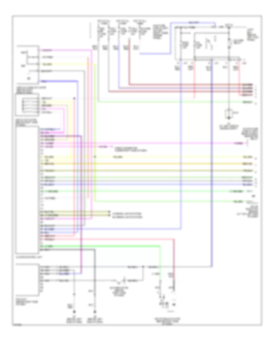
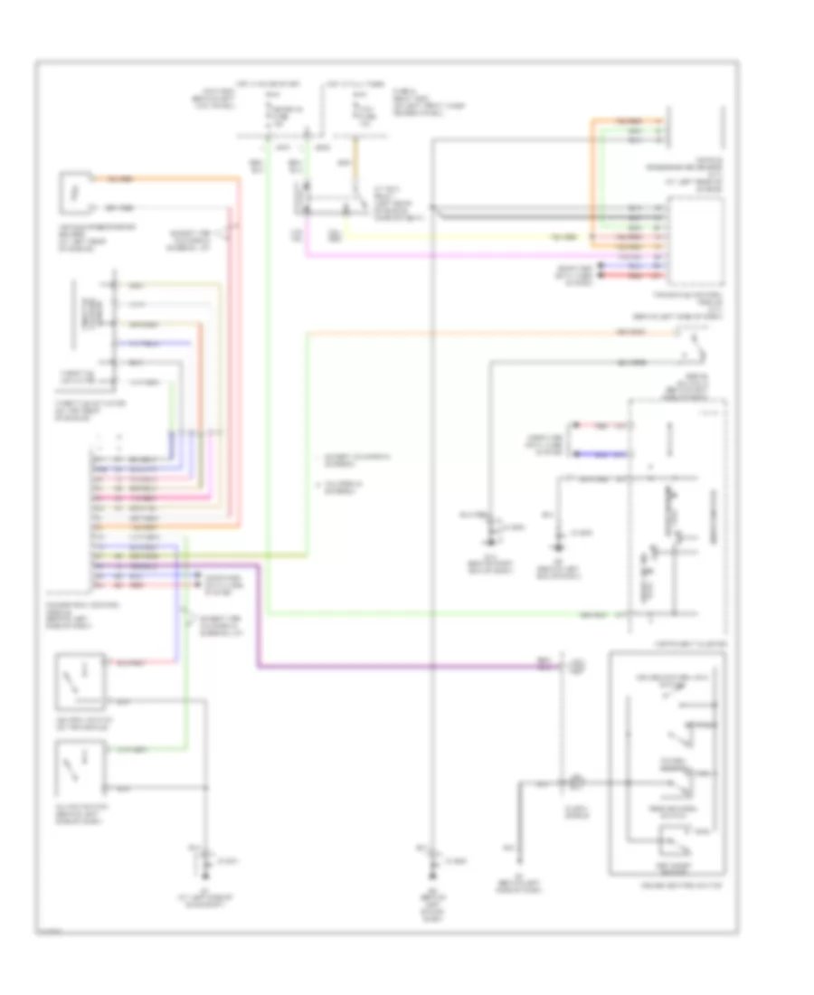
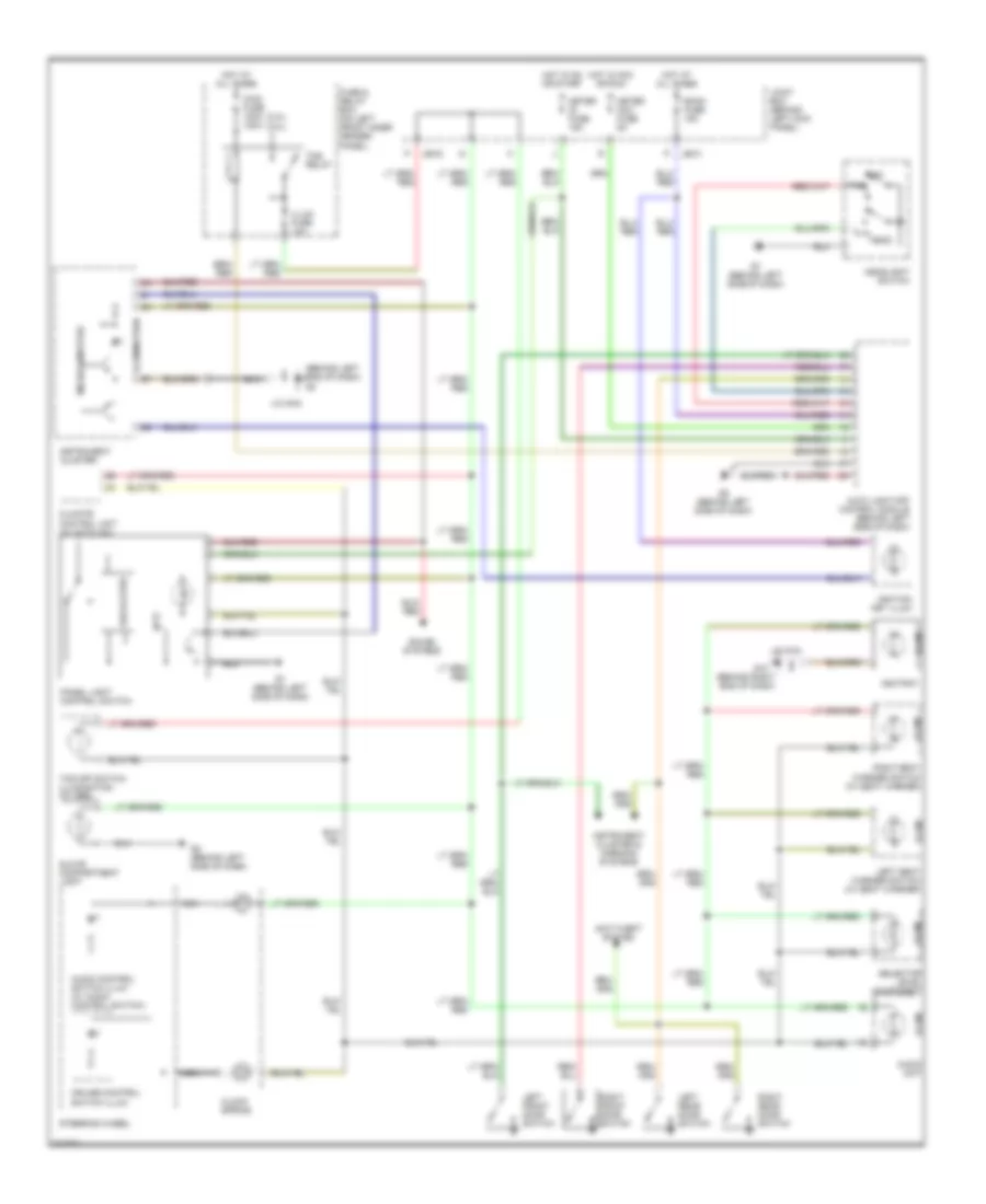
2.3L, Manual A/C Wiring Diagram for Mazda 6 i 2005
 https://portal-diagnostov.com/license.html
Automotive Electricians Portal FZCO
Automotive Electricians Portal FZCO
https://portal-diagnostov.com/license.html
https://portal-diagnostov.com/license.html
Automotive Electricians Portal FZCO
Automotive Electricians Portal FZCO
List of elements for 2.3L, Manual A/C Wiring Diagram for Mazda 6 i 2005:
- (behind left side of dash)
- 1ac
- A/c fuse 15a
- A/c relay (in main fuse & relay box)
- Acc
- Ad fan fuse 30a
- Air intake actuator (behind right side of dash)
- Airflow mode actuator (behind right side of dash)
- Ambient temperature sensor (at right front of engine compt)
- Blower fuse 40a
- Blower motor (behind right side of dash)
- Blower relay
- Center panel
- Cooling fan motor 1 (at left front of engine compt)
- Cooling fan motor 2 (at right front of engine compt)
- Cooling fan relay 1 (fan relay 3) (in main fuse & relay box)
- Cooling fan relay 2 (fan relay) (in main fuse & relay box)
- Cooling fan relay 3 (ad fan relay) (in main fuse & relay box)
- Cooling fan relay 4 (fan relay 2) (in main fuse & relay box)
- Driver
- Engine coolant temperature sensor (at left rear of engine)
- Evaporator temperature sensor (behind center of dash)
- Fan fuse 30a
- Fan switch
- G1 (at left side of engine compt)
- G4 (at right front of engine compt)
- G7 (behind left side of dash)
- Hot at all times
- Hot in on and start
- Ignition switch
- Jb-01
- Jb-02
- Jc-
- Jc-01
- Joint box (behind left kick panel)
- Lock
- Low
- Mag fuse 10a
- Magnetic clutch
- Main fuse & relay box (on left front inner fender panel)
- Meter ig fuse 15a
- Mid
- Mode switch
- Off
- Powertrain control module (pcm) (behind left side of dash)
- Rear window defroster relay (in main fuse & relay box)
- Refrigerant pressure switch (at right front corner of engine compt)
- Resistor
- Start
3.0L
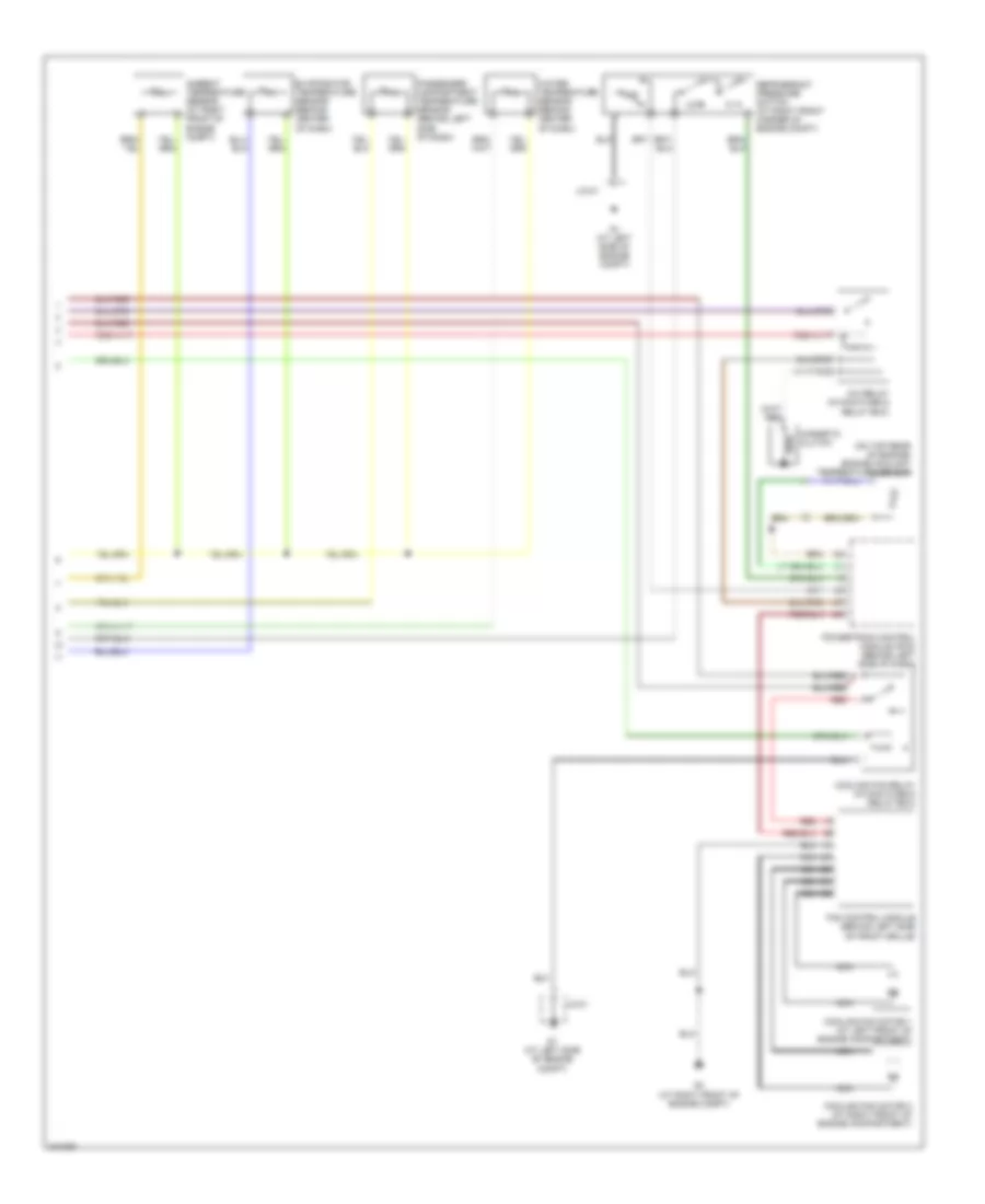
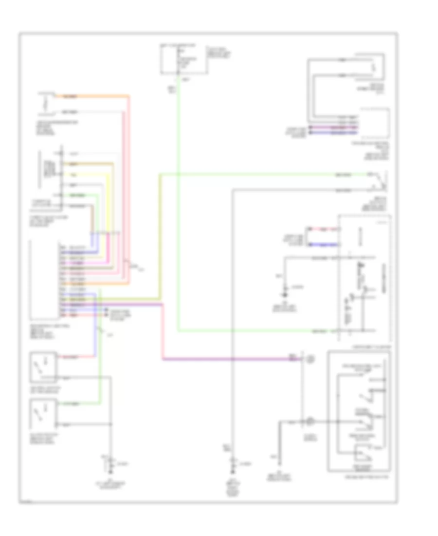
3.0L, Automatic A/C Wiring Diagram (1 of 2) for Mazda 6 i 2005
List of elements for 3.0L, Automatic A/C Wiring Diagram (1 of 2) for Mazda 6 i 2005:
- (in main fuse & relay box) rear window defroster relay
- A/c fuse 15a
- Air intake actuator (behind right side of dash)
- Air mix actuator (behind right side of dash)
- Airflow mode actuator (behind right side of dash)
- Blower fuse 40a
- Blower motor (behind right side of dash)
- Blower relay
- Check connector (under right side of dash)
- Climate control unit
- Def
- Eng bb fuse 5a
- Exterior lights system
- Fan 1 fuse 30a
- Fan 2 fuse 30a
- G1 (at left side of engine compt)
- G7 (behind left side of dash)
- G8 (behind left side of dash)
- Hot at all times
- Hot in on
- Interior lights system
- J-01
- J-02
- Jc-01
- Joint box (behind left kick panel)
- Mag fuse 10a
- Main fuse & relay box (on left front inner fender panel)
- Nca
- Pwm unit (behind right side of dash)
- Room fuse 15a
- Solar radiation sensor (at top left side of dash)
- Vent
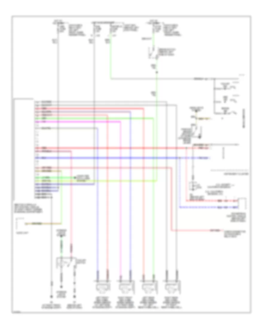
3.0L, Automatic A/C Wiring Diagram (2 of 2) for Mazda 6 i 2005
List of elements for 3.0L, Automatic A/C Wiring Diagram (2 of 2) for Mazda 6 i 2005:
- (on top rear of engine) engine coolant temperature sensor
- A/c relay (in main fuse & relay box)
- Ambient temperature sensor (at right front of engine compt)
- Cooling fan motor 1 (at left front of engine compartment)
- Cooling fan motor 2 (at right front of engine compartment)
- Cooling fan relay (in main fuse & relay box)
- Evaporator temperature sensor (behind center of dash)
- Fan control module (behind left side of front grille)
- G1 (at left side of engine compt)
- G4 (at right front of engine compt)
- J/c-01
- Jc-01
- Low
- Magnetic clutch
- Mid
- Nca
- Passenger compartment temperature sensor (behind left side of dash)
- Powertrain control module (pcm) (behind left side of dash)
- Red
- Refrigerant pressure switch (at right front corner of engine compt)
- Water temperature sensor (behind center of dash)
ANTI-LOCK BRAKES
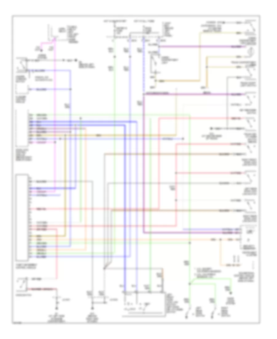
Anti-lock Brakes Wiring Diagram for Mazda 6 i 2005
List of elements for Anti-lock Brakes Wiring Diagram for Mazda 6 i 2005:
- (at right front of engine compt)
- (behind left side of dash)
- 2.3l: california emission, 3.0l
- 2.3l: except california emission
- Abs fuse 60a
- Abs ind
- Abs/tcs hydraulic unit/control module (at right front corner of engine compartment)
- Audio unit
- Brake ind
- Brake switch (behind left
- Check connector (in main fuse & relay box)
- Computer data lines system
- G2 (behind left end of dash)
- Headlights system
- Hot at all times
- Hot in on or start
- Ill
- Instrument cluster
- Interior lights system
- J-01
- J-02
- Jc g-02
- Joint box (behind left kick panel)
- Left front abs wheel speed sensor (at left side of engine compt)
- Left rear abs wheel speed sensor (at left rear wheelwell)
- Main fuse & relay box (on left front inner fender panel)
- Meter ig fuse 15a
- Micro-computer
- Parking brake switch (at base of parking brake lever)
- Powertrain control module (behind left side of dash)
- Red
- Right front abs wheel speed sensor (at right side of engine compt)
- Right rear abs wheel speed sensor (at right rear wheelwell)
- Sas fuse 15a
- Side of dash)
- Stop fuse 15a
- Tcs off ind
- Tcs off switch
ANTI-THEFT
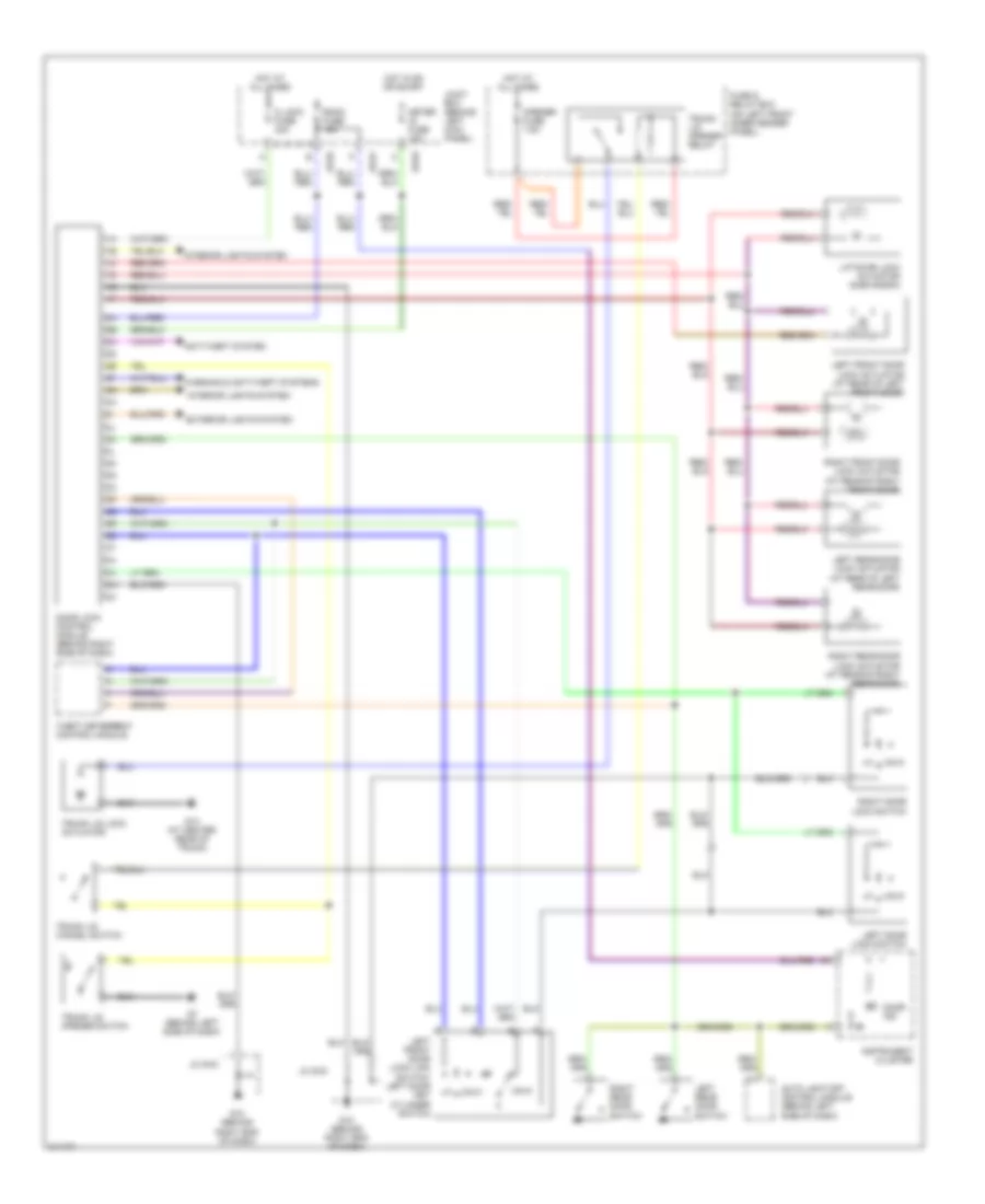
Forced Entry Wiring Diagram for Mazda 6 i 2005
List of elements for Forced Entry Wiring Diagram for Mazda 6 i 2005:
- (hatchback)
- (wagon)
- 2.3l: california emission, 3.0l
- 2.3l: except california emission
- Automatic a/c
- Cargo compartment light
- Cargo compartment light switch
- Door lock control module (behind right side of dash)
- Door locks system
- Flasher control module
- Fuse & relay box (on left front inner fender)
- G1 (at left side of engine compartment)
- G10 (behind right end of dash)
- G14 (at center rear of trunk)
- G19
- G8 (behind left side of dash)
- Hatchback/wagon
- Hazard warning switch
- Hood switch
- Horn relay
- Horns system
- Hot at all times
- Hot in on or start
- Instrument cluster
- Jb-01 p
- Jb-03 e
- Jb-05 e
- Jc g-01
- Jc g-03
- Joint box (behind left kick panel)
- Key reminder switch
- Left front door lock link switch/ left door key cylinder switch
- Left rear door lock link switch
- Left rear door switch
- M/c
- Manual a/c
- Meter ig fuse 15a
- Powertrain control module (behind left side of dash)
- Right front door lock link switch
- Right rear door lock link switch
- Right rear door switch
- Room fuse 15a
- Security indicator
- Sedan
- Theft deterrent control module
- Trunk compartment light
- Trunk compt light switch
- Trunk key cylinder switch (sedan)
- Unlk
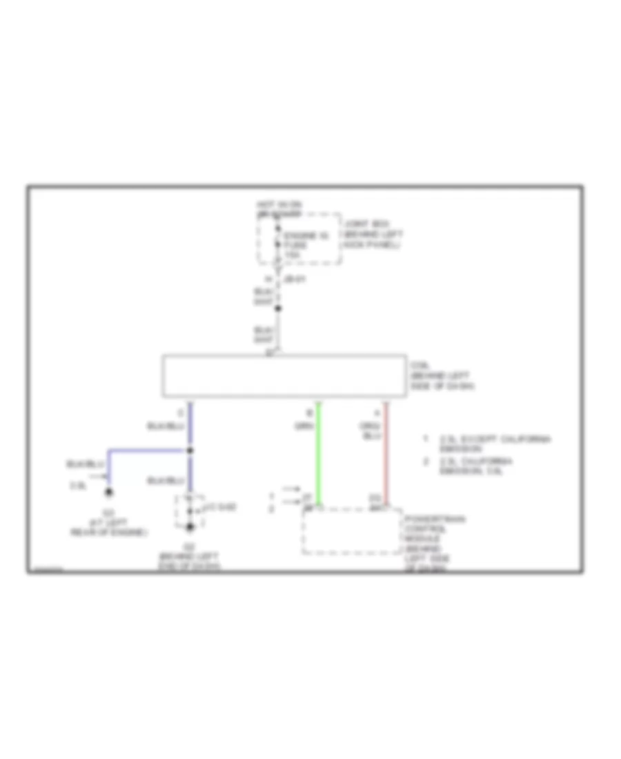
Immobilizer Wiring Diagram for Mazda 6 i 2005
List of elements for Immobilizer Wiring Diagram for Mazda 6 i 2005:
- 2.3l: california emission, 3.0l
- 2.3l: except california emission
- 3.0l
- Coil (behind left side of dash)
- Engine ig fuse 15a
- G2 (behind left end of dash)
- G3 (at left rear of engine)
- Hot in on or start
- Jb-01
- Jc g-02
- Joint box (behind left kick panel)
- Powertrain control module (behind left side of dash)
COMPUTER DATA LINES
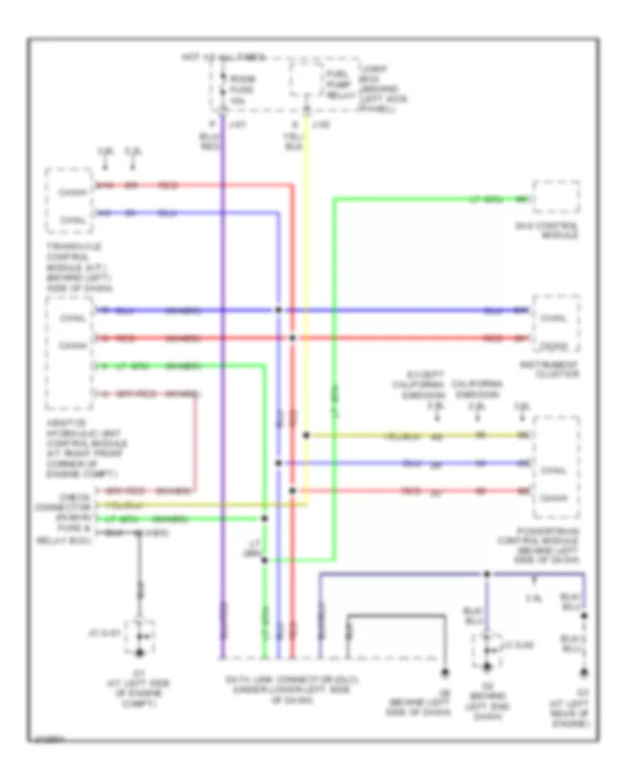
Computer Data Lines Wiring Diagram for Mazda 6 i 2005
List of elements for Computer Data Lines Wiring Diagram for Mazda 6 i 2005:
- (at left rear of engine)
- (w/abs)
- 2.3l
- 3.0l
- A14
- Abs/tcs hydraulic unit control module (at right front corner of engine compt)
- California emission
- Can-h
- Can-l
- Check connector (in main fuse &
- Data link connector (dlc) (under lower left side of dash)
- Except california emission 2.3l
- Fuel pump relay
- G1 (at left side of engine compt)
- G2 (behind left end dash)
- G8 (behind left side of dash)
- Hot at all times
- Instrument cluster
- J-01
- J-02
- Jc g-01
- Jc g-02
- Joint box (behind left kick panel)
- Powertrain control module (behind left side of dash)
- Red
- Relay box)
- Room fuse 15a
- Sas control module
- Transaxle control module (a/t) (behind left) side of dash)
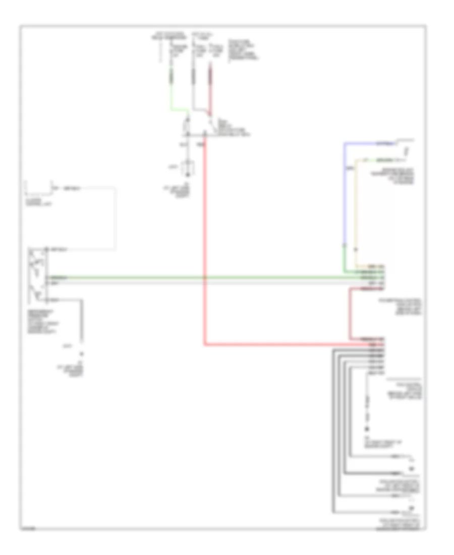
COOLING FAN
2.3L
2.3L, Cooling Fan Wiring Diagram for Mazda 6 i 2005
List of elements for 2.3L, Cooling Fan Wiring Diagram for Mazda 6 i 2005:
- 1ac
- Ad fan fuse 30a
- Center panel
- Cooling fan motor 1 (at left front of engine compt)
- Cooling fan motor 2 (at right front of engine compt)
- Cooling fan relay 1 (fan relay 3) (in main fuse & relay box)
- Cooling fan relay 2 (fan relay) (in main fuse & relay box)
- Cooling fan relay 3 (ad fan relay) (in main fuse & relay box)
- Cooling fan relay 4 (fan relay 2) (in main fuse & relay box)
- Engine coolant temperature sensor (at left rear of engine)
- Fan fuse 30a
- G1 (at left side of engine compt)
- G4 (at right front of engine compt)
- Hot at all times
- Hot in on & start
- Jb-02
- Jc-01
- Joint box (behind left kick panel)
- Low
- Main fuse & relay box (on left front inner fender panel)
- Meter ig fuse 15a
- Mid
- Powertrain control module (pcm) (behind left side of dash)
- Refrigerant pressure switch (right front corner of engine compt)
3.0L
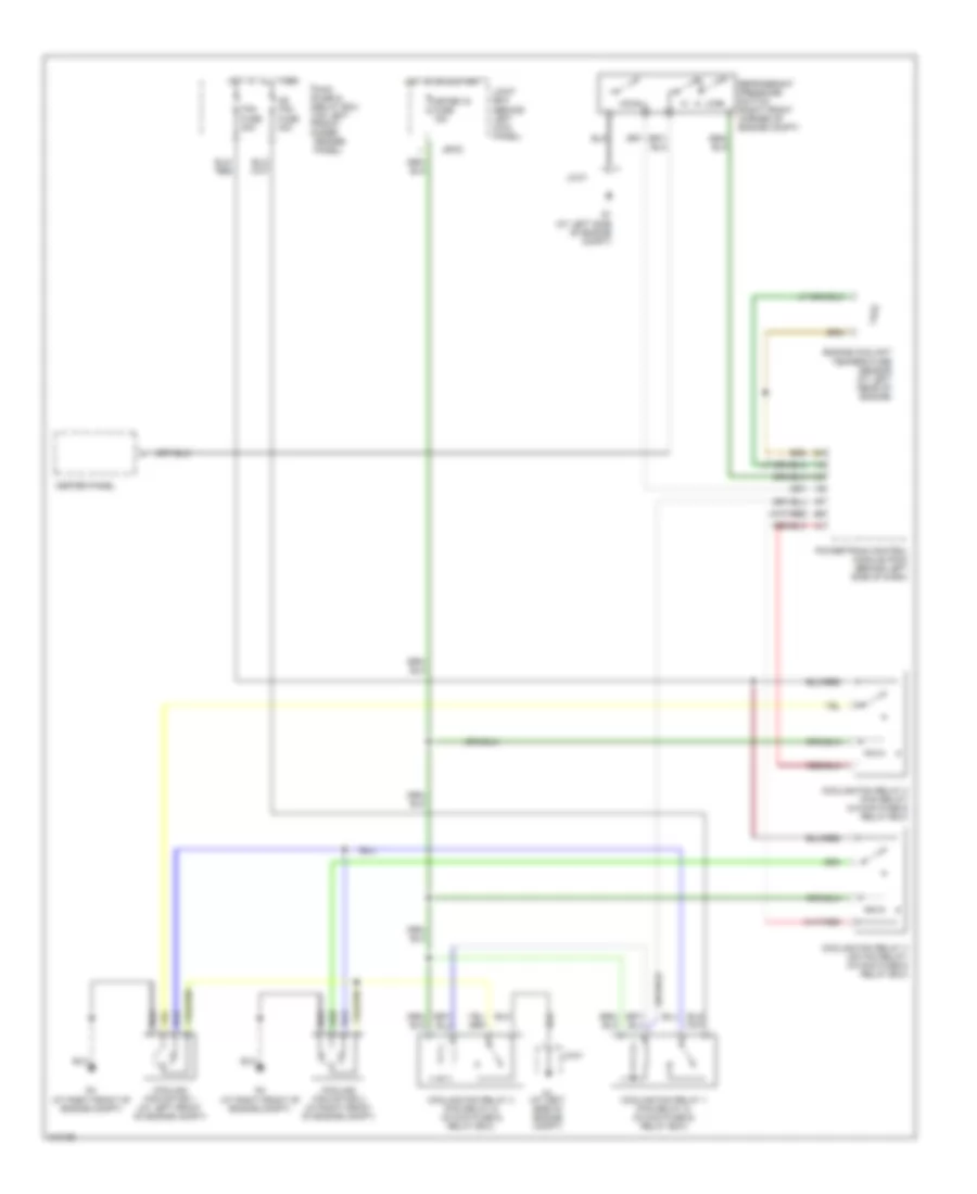
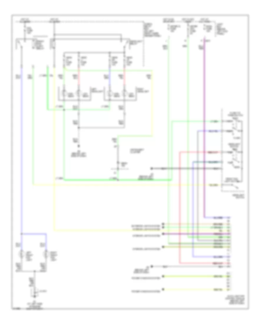
3.0L, Cooling Fan Wiring Diagram for Mazda 6 i 2005
List of elements for 3.0L, Cooling Fan Wiring Diagram for Mazda 6 i 2005:
- Climate control unit
- Cooling fan motor 1 (at left front of engine compartment)
- Cooling fan motor 2 (at right front of engine compartment)
- Eng bb fuse 5a
- Engine coolant temperature sensor (on top rear of engine)
- Fan relay (in main fuse and relay box)
- Fan 1 fuse 30a
- Fan 2 fuse 30a
- Fan control module (behind left side of front grille)
- G1 (at left side of engine compt)
- G4 (at right front of engine compt)
- Hot at all times
- Hot with main relay energizied
- Jc-01
- Low
- Main fuse & relay box (on left front inner fender panel)
- Mid
- Nca
- Powertrain control module (pcm) (behind left side of dash)
- Red
- Refrigerant pressure switch (at right front corner of engine compt)
CRUISE CONTROL
2.3L
2.3L, Cruise Control Wiring Diagram for Mazda 6 i 2005
List of elements for 2.3L, Cruise Control Wiring Diagram for Mazda 6 i 2005:
- 4ab
- At main relay (left rear of engine compartment)
- Brake switch 2 (behind left side of dash)
- California
- Cancel switch
- Clock- spring
- Clutch switch (behind left side of dash)
- Computer data lines system
- Cruise control main switch
- Cruise control switch
- Cruise main ind
- Cruise set ind
- Emission
- Except california emission
- Except for california emission, m/t
- Fuse & relay box (on left front inner fender panel)
- G1 (at left side of eng compt)
- G10 (behind right end of dash)
- G2 (behind left end of dash)
- G7 (behind left side of dash)
- Hot at all times
- Hot in on or start
- Instrument cluster
- Jb-01
- Jb-02
- Jc g-01
- Jc g-02
- Jc g-03
- Joint box (behind left kick panel)
- Meter ig fuse 15a
- Microcomputer
- Neutral switch (on transaxle)
- Position throttle
- Powertrain control module (behind left side of dash)
- Red
- Resume/accel switch
- Sensor
- Set/coast switch
- Tcm fuse 10a
- Throttle actuator
- Throttle actuator (on top rear of engine)
- Transaxle control module (a/t) (behind left side of dash)
- Vehicle speedometer sensor (a/t) (at left rear of engine)
- Vehicle speedometer sensor (at left rear of engine)
3.0L
3.0L, Cruise Control Wiring Diagram for Mazda 6 i 2005
List of elements for 3.0L, Cruise Control Wiring Diagram for Mazda 6 i 2005:
- A14
- B19
- B20
- Brake switch 2 (behind left side of dash)
- Cancel switch
- Clock- spring
- Clutch switch (behind left side of dash)
- Computer data lines system
- Cruise control main switch
- Cruise control switch
- Cruise main ind
- Cruise set ind
- G1 (at left side of eng compt)
- G10 (behind right end of dash)
- G2 (behind left end of dash)
- G7 (behind left side of dash)
- Hot in on or start
- Instrument cluster
- Jb-01
- Jc g-01
- Jc g-02
- Jc g-03
- Joint box (behind left kick panel)
- M/t
- Meter ig fuse 15a
- Microcomputer
- Nca
- Neutral switch (on transaxle)
- Position throttle
- Powertrain control module (behind left side of dash)
- Red
- Resume/accel switch
- Sensor
- Set/coast switch
- Throttle actuator
- Throttle actuator (on top rear of engine)
- Transaxle control module (a/t) (behind left side of dash)
- Vehicle speed sensor (a/t)
- Vehicle speedometer sensor (at rear of engine)
DEFOGGERS
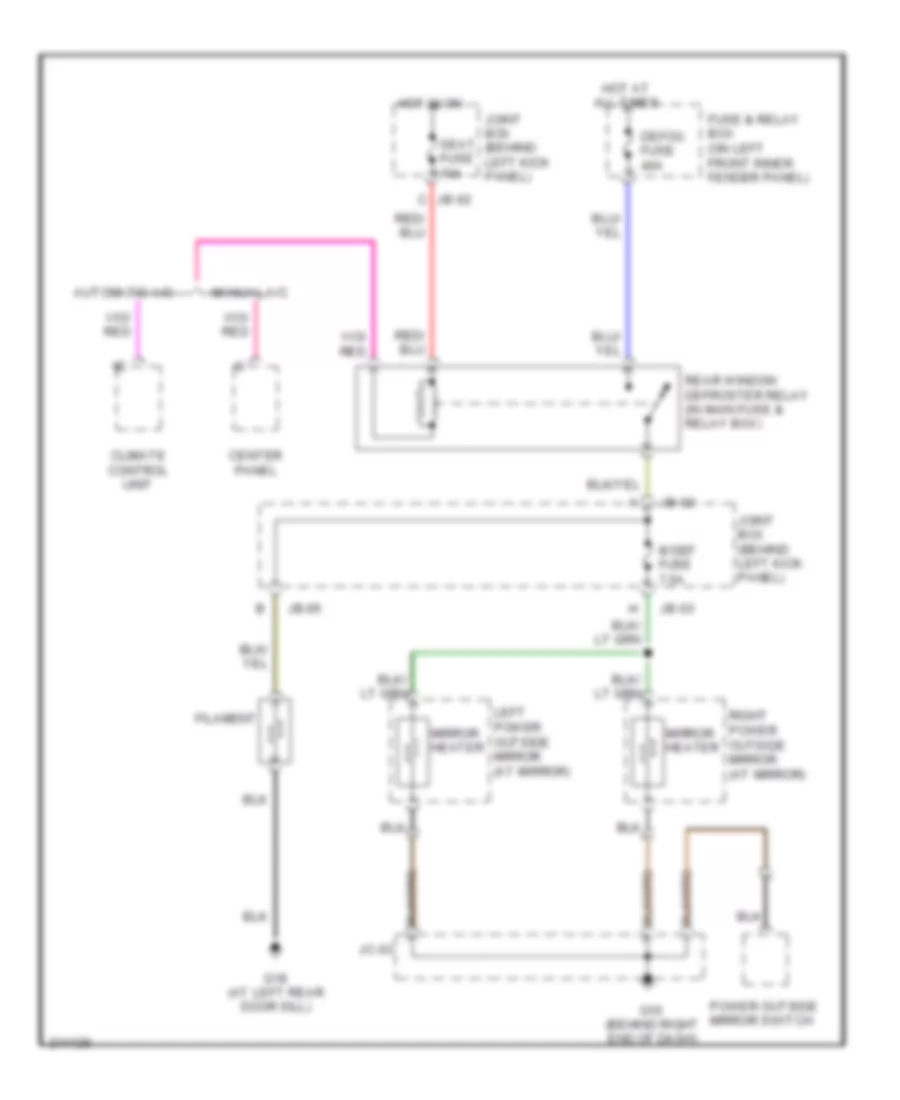
Defoggers Wiring Diagram for Mazda 6 i 2005
List of elements for Defoggers Wiring Diagram for Mazda 6 i 2005:
- Automatic a/c
- Center panel
- Climate control unit
- Defog fuse 40a
- Filament
- Fuse & relay box (on left front inner fender panel)
- G10 (behind right end of dash)
- G18 (at left rear door sill)
- Hot at all times
- Hot in on
- Jb-02
- Jb-03
- Jb-05
- Jc-03
- Joint box (behind left kick panel)
- Left power outside mirror (at mirror)
- M def fuse 7.5a
- Manual a/c
- Mirror heater
- Power outside mirror switch
- Rear window defroster relay (in main fuse & relay box)
- Right power outside mirror (at mirror)
- Seat fuse 15a
ENGINE PERFORMANCE
2.3L
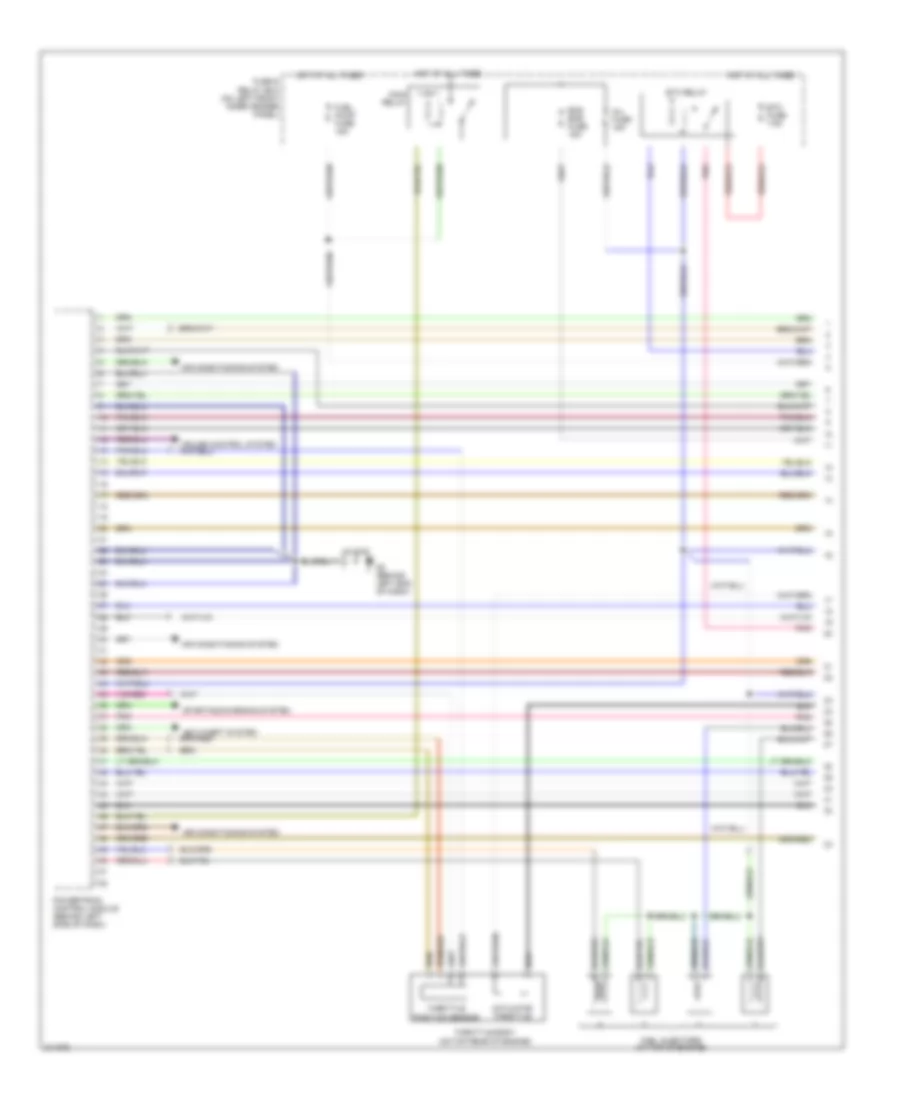
2.3L, Engine Performance Wiring Diagram, California (1 of 4) for Mazda 6 i 2005
List of elements for 2.3L, Engine Performance Wiring Diagram, California (1 of 4) for Mazda 6 i 2005:
- (on top rear of engine)
- Actuator throttle
- Air conditioning system
- Eng bar fuse 15a
- Etc fuse 7.5a
- Etc relay
- Fuel injectors (at top of engine)
- Fuel pump fuse 15a
- Fuse & relay box (on left front inner fender panel)
- G2 (behind left end of dash)
- Hot at all times
- Inj fuse 15a
- Jc g-02
- Main relay
- Pnk
- Powertrain control module (behind left side of dash)
- Starting/charging system
- Throttle body
- Throttle position sensor
2.3L, Engine Performance Wiring Diagram, California (2 of 4) for Mazda 6 i 2005
List of elements for 2.3L, Engine Performance Wiring Diagram, California (2 of 4) for Mazda 6 i 2005:
- (above accelerator pedal assembly) accelerator pedal position sensor
- (at right rear of engine) camshaft position sensor
- (on front of engine) crankshaft position sensor
- (on left side of engine, below power steering pump) knock sensor
- (on rear of engine) mass air flow/intake air temperature sensor
- Barometric pressure sensor (at left rear of engine compt)
- Engine coolant temperature sensor (at left rear of engine)
- G2 (behind left end of dash)
- Jc g-02
- Manifold absolute pressure sensor (at left rear of engine)
- Nca nca
- Pnk
- Variable tumble shutter valve switch
2.3L, Engine Performance Wiring Diagram, California (3 of 4) for Mazda 6 i 2005
List of elements for 2.3L, Engine Performance Wiring Diagram, California (3 of 4) for Mazda 6 i 2005:
- (behind left end of dash)
- (in main fuse & relay box) check connector
- (under rear seat, on fuel tank) fuel pump unit
- 5hb/wagon
- Engine ig fuse 15a
- Evap system leak detection pump (under rear of vehicle, near fuel pump)
- Front heated oxygen sensor (at left rear of engine compartment)
- Fuel pump
- Fuel pump relay
- G13 (at left rear door sill)
- G2 (behind left end of dash)
- Hot in run or start
- Instrument cluster
- Jb-01
- Jb-02
- Jb-05
- Jc g-02
- Joint box (behind left kick panel)
- Meter ig fuse 15a
- Micro computer
- Middle heated oxygen sensor
- Mil ind
- Nca
- Oil control valve (at right front of engine)
- Pnk
- Purge solenoid valve (on top rear of engine)
- Rear heated oxygen sensor (at left rear of engine compartment)
- Sender unit fuel gauge
- Variable air duct control solenoid valve (at left front of engine compt)
- Variable intake-air system control (at left front engine)
- Variable tumble control solenoid valve (on left front side of engine)
2.3L, Engine Performance Wiring Diagram, California (4 of 4) for Mazda 6 i 2005
List of elements for 2.3L, Engine Performance Wiring Diagram, California (4 of 4) for Mazda 6 i 2005:
- (at left front side of engine) power steering pressure switch
- (behind left side of dash) brake switch
- (on top rear of engine)
- Anti-theft system
- Capacitor (at right rear of engine)
- Computer data lines system
- Cooling fans system
- Egr valve (on top rear of engine)
- Eng+b fuse 7.5a
- Fuse & relay box (on left front inner fender panel)
- G10 (behind right end of dash)
- G2 (behind left end of dash)
- Hot at all times
- Ignition coil 1
- Ignition coil 2
- Ignition coil 3
- Ignition coil 4
- Jc g-02
- Jc g-03
- Pnk
- Powertrain control module (behind left side of dash)
- Red
- Starting/charging system
- Stop fuse 15a
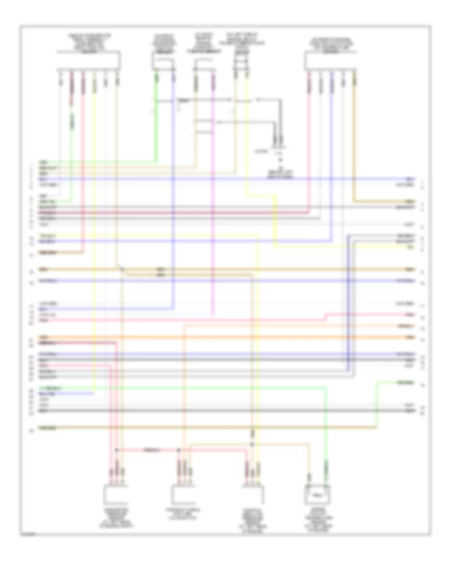
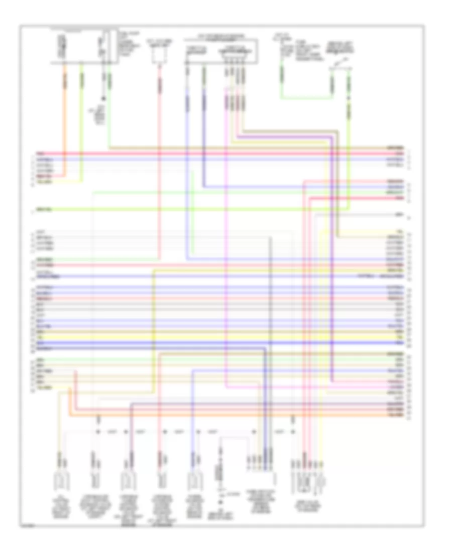
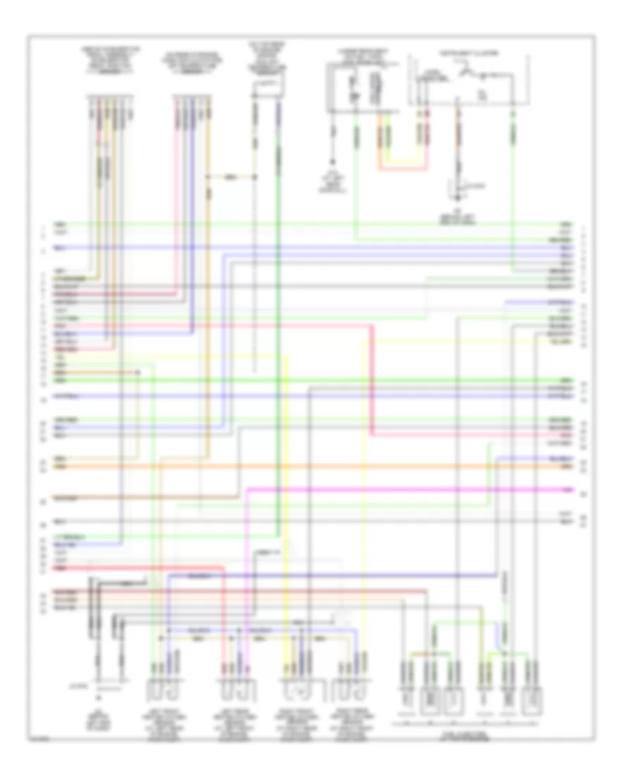
2.3L, Engine Performance Wiring Diagram, Except California (1 of 4) for Mazda 6 i 2005
List of elements for 2.3L, Engine Performance Wiring Diagram, Except California (1 of 4) for Mazda 6 i 2005:
- (under lower left side of dash) data link connector 2
- 1aa
- 1ab
- 1ac
- 1ad
- 2aa
- 2ab
- 2ac
- 2ad
- Air conditioning system
- Anti-theft system
- Barometric pressure sensor (at left rear of engine compt)
- Capacitor (at right rear of engine)
- Computer data lines system
- Eng b + fuse 7.5a
- Eng bar 2 fuse 15a
- Eng bar fuse 10a
- Engine coolant temperature sensor (at left rear of engine)
- Engine ig fuse 15a
- Etc fuse 7.5a
- Etc relay
- Fuel pump fuse 15a
- Fuse & relay box (on left front inner fender panel)
- G2 (behind left end of dash)
- Hot at all times
- Hot in run or start
- Ignition coil (on top rear of engine)
- Inj fuse 15a
- Instrument cluster
- Jb-01
- Jb-02
- Jc g-02
- Joint box (behind left kick panel)
- Main relay
- Manifold absolute pressure sensor (at left rear of engine)
- Meter ig fuse 15a
- Micro comp- uter
- Mil ind
- Pnk
- Powertrain control module (behind left side of dash)
- Red
- Starting/ charging system
- Variable tumble shutter switch
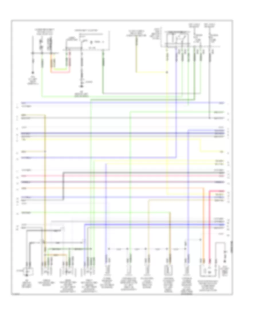
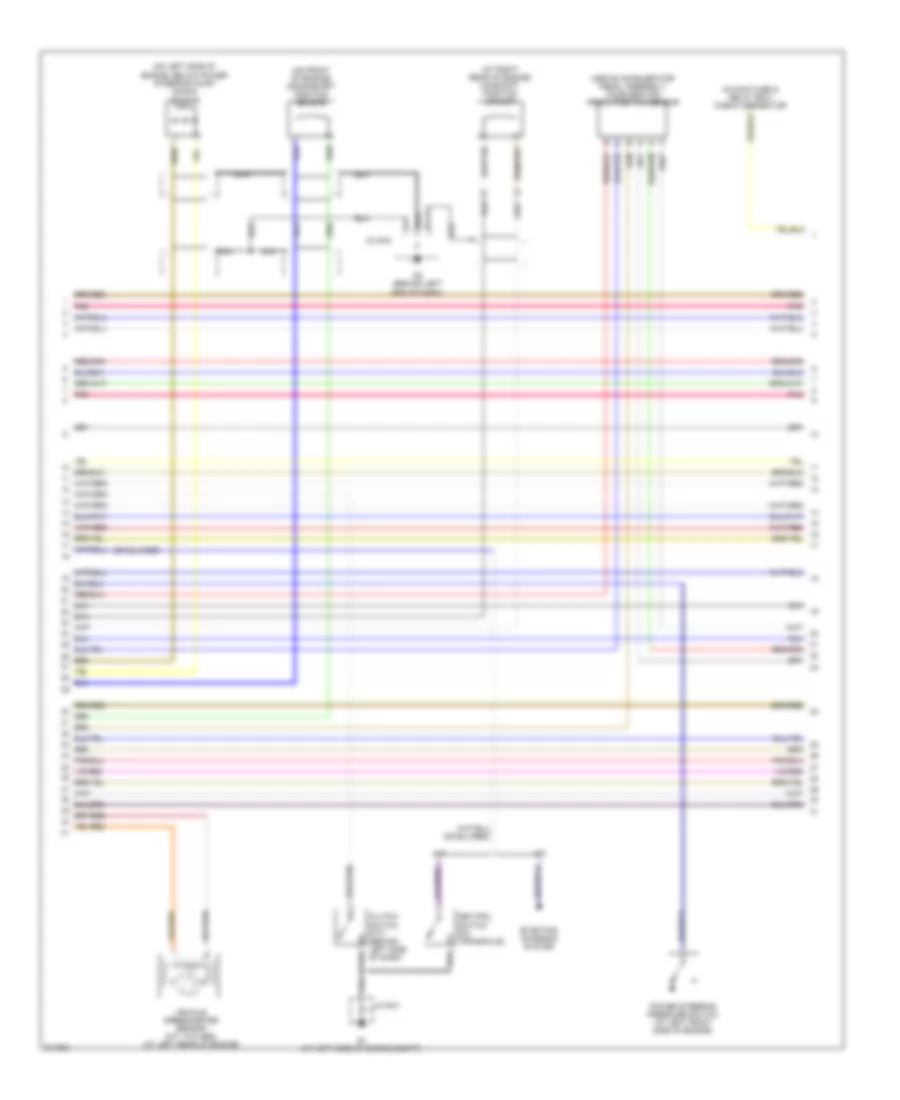
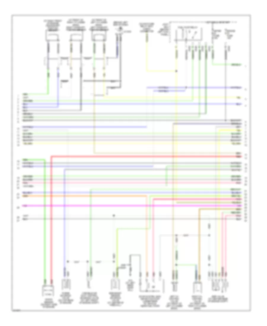
2.3L, Engine Performance Wiring Diagram, Except California (2 of 4) for Mazda 6 i 2005
List of elements for 2.3L, Engine Performance Wiring Diagram, Except California (2 of 4) for Mazda 6 i 2005:
- (behind left side of dash) brake switch
- (m/t, w/o abs) audio unit
- (on top rear of engine) throttle body
- Egr valve (on top rear of engine)
- Fuel gauge sender unit
- Fuel pump
- Fuel pump unit (under rear seat, on fuel tank)
- Fuse & relay box (on left front inner fender panel)
- G13 (at left rear door sill)
- G2 (behind left end of dash)
- Hot at all times
- Jc g-02
- Mass air flow/ intake air temperature sensor (on rear of engine)
- Oil control valve (at right front of engine)
- Pnk
- Purge solenoid valve (on top rear of engine)
- Stop fuse 15a
- Throttle actuator
- Throttle position sensor
- Variable air duct control solenoid valve (at left front of engine compt)
- Variable intake-air system control solenoid valve (at left front of engine)
- Variable tumble control solenoid valve (on left front side of engine)
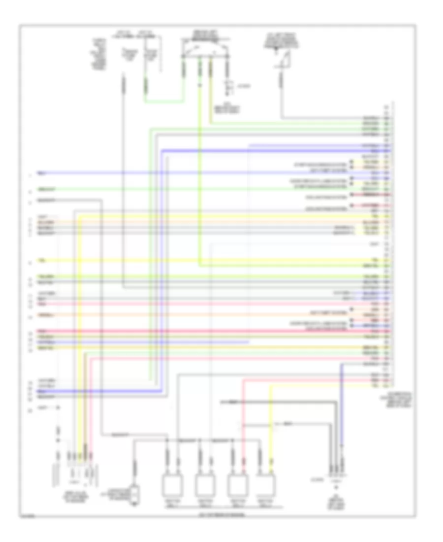
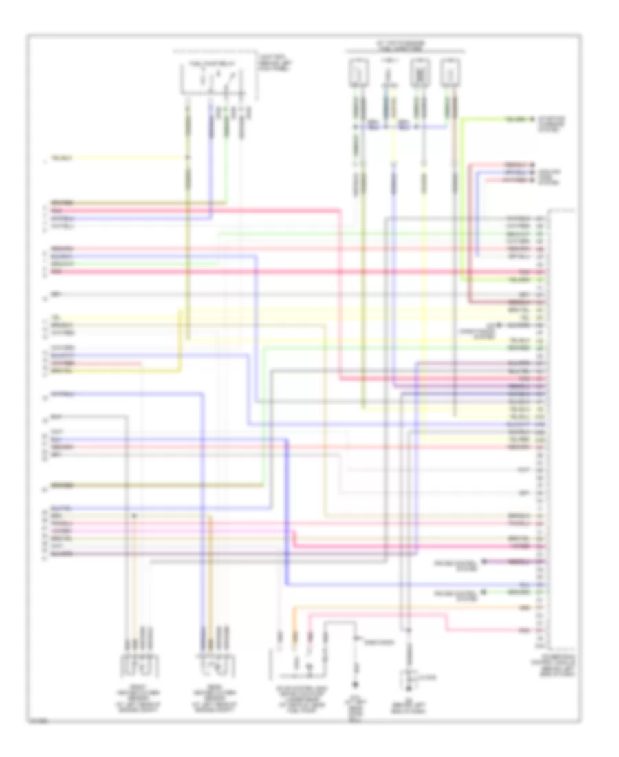
2.3L, Engine Performance Wiring Diagram, Except California (3 of 4) for Mazda 6 i 2005
List of elements for 2.3L, Engine Performance Wiring Diagram, Except California (3 of 4) for Mazda 6 i 2005:
- (above accelerator pedal assembly) accelerator pedal position sensor
- (at right rear of engine) camshaft position sensor
- (in main fuse & relay box) check connector
- (on front of engine) crankshaft position sensor
- (on left side of engine, below power steering pump) knock sensor
- A/t
- Clutch switch (m/t) (behind left side of dash)
- G1 (at left side of engine compt)
- G2 (behind left end of dash)
- Jc g-01
- Jc g-02
- M/t
- Nca
- Neutral switch (on transaxle)
- Pnk
- Power steering pressure switch (at left front side of engine)
- Starting/ charging system
- Vehicle speedometer sensor (m/t, w/o abs) (at left rear of engine)
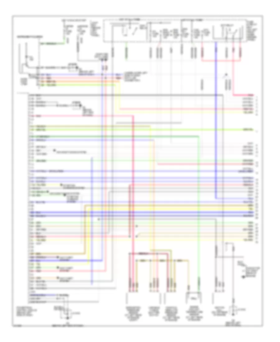
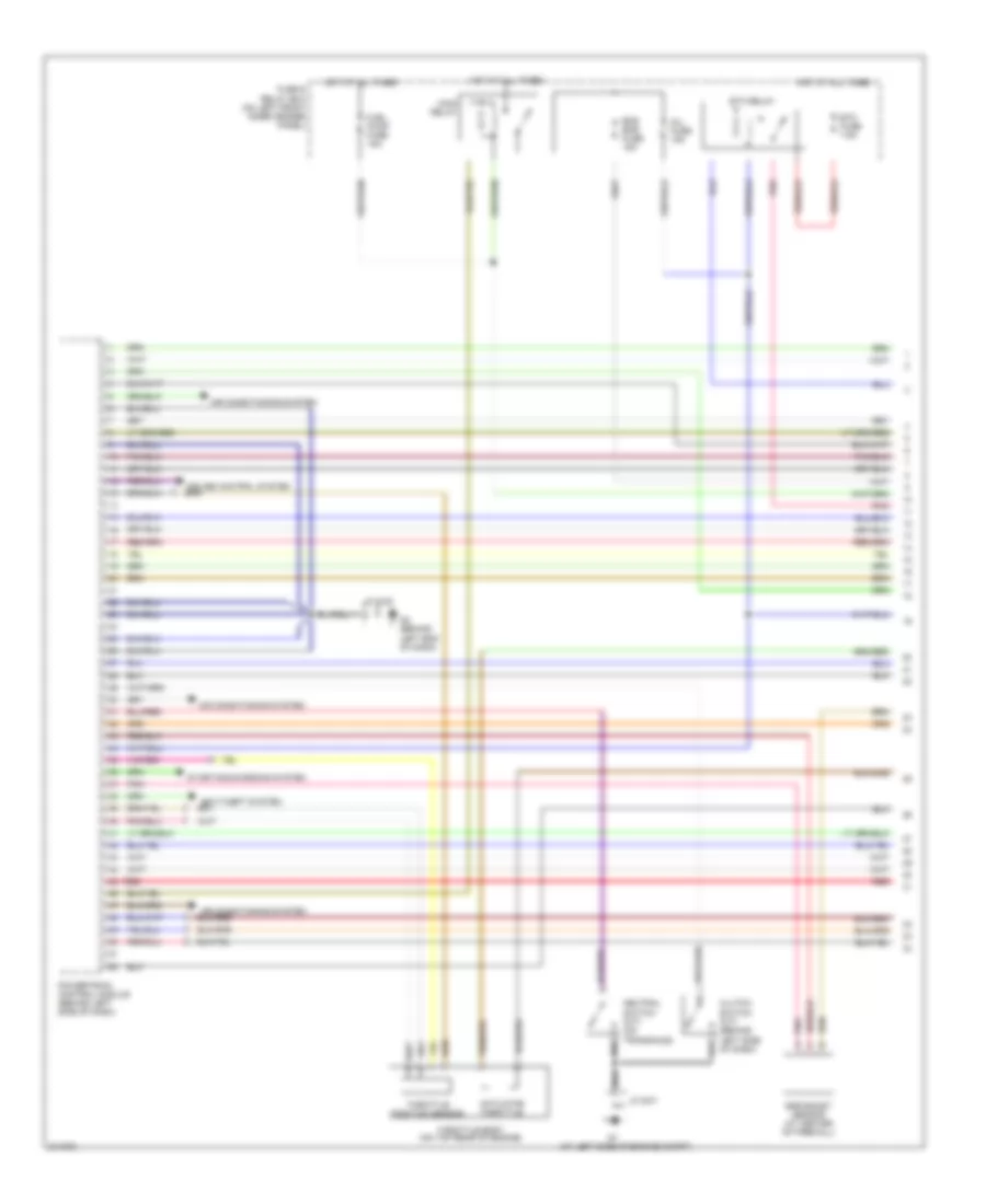
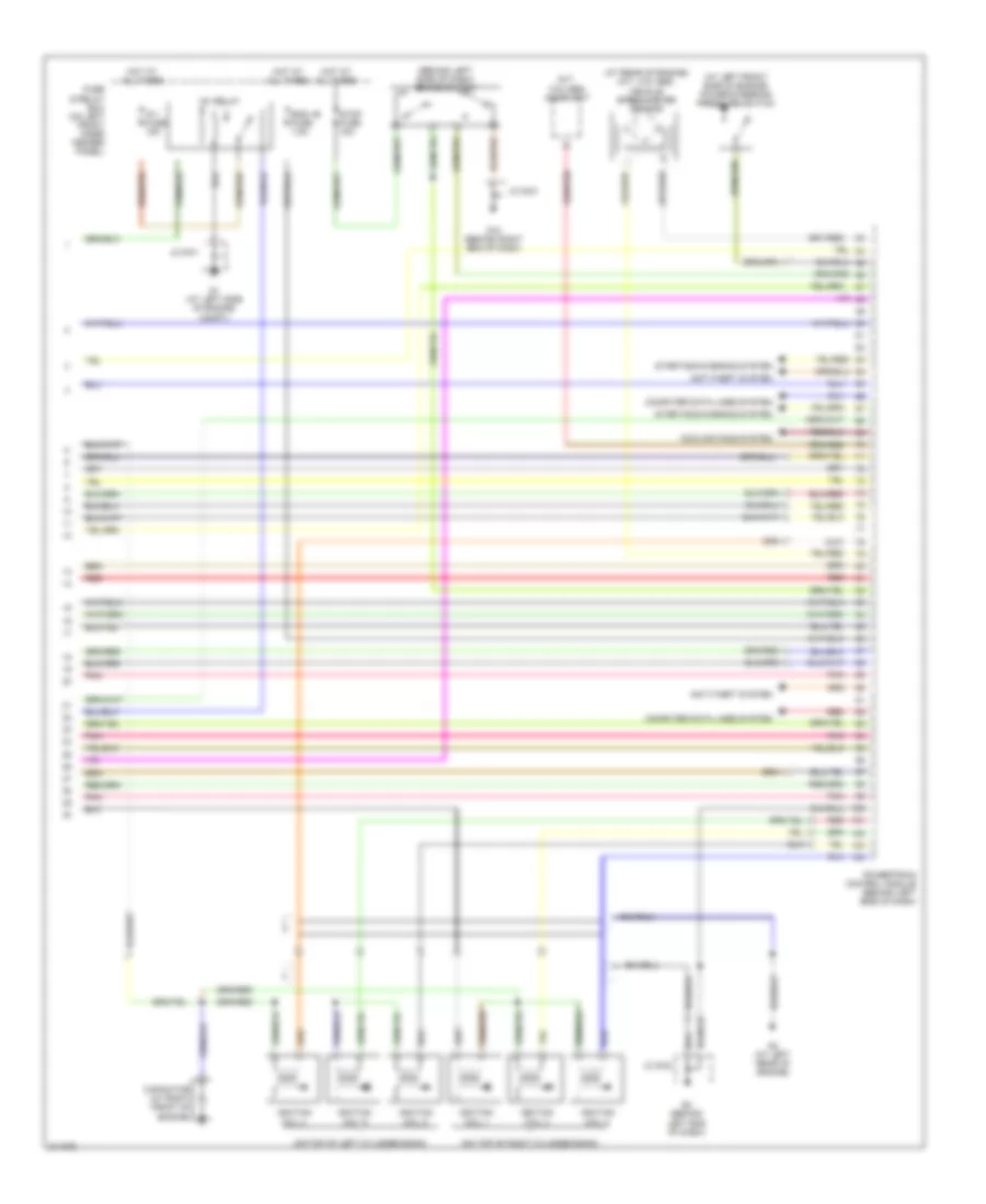
2.3L, Engine Performance Wiring Diagram, Except California (4 of 4) for Mazda 6 i 2005
List of elements for 2.3L, Engine Performance Wiring Diagram, Except California (4 of 4) for Mazda 6 i 2005:
- (at top of engine) fuel injectors
- 3aa
- 4aa
- 4ab
- 4ac
- 4ad
- 5hb/wagon
- Air conditioning system
- Cooling fans system
- Cruise control system
- Evap system leak detection pump (under rear of vehicle, near fuel pump)
- Front heated oxygen sensor (at left rear of engine compt)
- Fuel pump relay
- G13 (at left rear door sill)
- G2 (behind left end of dash)
- Jb-02
- Jb-05
- Jc g-02
- Joint box (behind left kick panel)
- Pnk
- Powertrain control module (behind left side of dash)
- Rear heated oxygen sensor (at left rear of engine compt)
- Starting/ charging system
3.0L
3.0L, Engine Performance Wiring Diagram (1 of 4) for Mazda 6 i 2005
List of elements for 3.0L, Engine Performance Wiring Diagram (1 of 4) for Mazda 6 i 2005:
- (at left side of engine compt)
- Actuator throttle
- Air conditioning system
- Clutch switch (m/t) (behind left side of dash)
- Egr boost sensor (at center of firewall)
- Eng bar fuse 15a
- Etc fuse 7.5a
- Etc relay
- Fuel pump fuse 15a
- Fuse & relay box (on left front inner fender panel)
- G2 (behind left end of dash)
- Hot at all times
- Inj fuse 15a
- Jc g-01
- Jc g-02
- Main relay
- Neutral switch (m/t) (on transaxle)
- Pnk
- Powertrain control module (behind left side of dash)
- Red
- Starting/charging system
- Throttle body (on top rear of engine)
- Throttle position sensor
3.0L, Engine Performance Wiring Diagram (2 of 4) for Mazda 6 i 2005
List of elements for 3.0L, Engine Performance Wiring Diagram (2 of 4) for Mazda 6 i 2005:
- (above accelerator pedal assembly) accelerator pedal position sensor
- (behind left end of dash)
- (on rear of engine) mass air flow/intake air temperature sensor
- (on top rear of engine) engine coolant temperature sensor
- (under rear seat, on fuel tank) fuel pump unit
- Fuel gauge sender unit
- Fuel injectors (at top of engine)
- Fuel pump
- G13 (at left rear door sill)
- G2 (behind left end of dash)
- Instrument cluster
- Jc g-02
- Left front heated oxygen sensor (at left rear of engine, in exhaust)
- Left rear heated oxygen sensor (at left front of engine, in exhaust)
- Micro computer
- Mil ind
- Nca
- Pnk
- Red
- Right front heated oxygen sensor (at right rear of engine, in exhaust)
- Right rear heated oxygen sensor (at right front of engine, in exhaust)
3.0L, Engine Performance Wiring Diagram (3 of 4) for Mazda 6 i 2005
List of elements for 3.0L, Engine Performance Wiring Diagram (3 of 4) for Mazda 6 i 2005:
- (at front of left cylinder bank) left camshaft position sensor
- (at front of right cylinder bank) right camshaft position sensor
- (at right front of engine) crankshaft position sensor
- (behind left end of dash) g2
- (in main fuse/ relay box) check connector
- 5hb/ wagon
- Egr boost sensor solenoid valve (at center of firewall)
- Egr valve (at center rear of engine compt)
- Engine ig fuse 15a
- Evap system leak detection pump (under rear of vehicle, near fuel pump)
- Fuel pump relay
- G13 (at left rear door sill)
- Hot in run or start
- Jb-01
- Jb-02
- Jb-05
- Jc g-02
- Joint box (behind left kick panel)
- Knock sensor (on right side of engine)
- Left oil control valve (at front of left cylinder bank)
- Meter ig fuse 15a
- Nca
- Pnk
- Purge solenoid valve (on top rear of engine)
- Red
- Right oil control valve (at front of right cylinder bank)
- Variable air duct control solenoid valve (at left front of engine compt)
3.0L, Engine Performance Wiring Diagram (4 of 4) for Mazda 6 i 2005
List of elements for 3.0L, Engine Performance Wiring Diagram (4 of 4) for Mazda 6 i 2005:
- (at left front side of engine) power steering pressure switch
- (at rear of engine) (m/t, w/o abs) vehicle speedometer sensor
- (behind left side of dash) brake switch
- (m/t, w/o abs) audio unit
- (on top of left cylinder bank)
- (on top of right cylinder bank)
- Anti-theft system
- Capacitor (at right front of engine)
- Computer data lines system
- Cooling fans system
- Eng +b fuse 7.5a
- Fuse & relay box (on left front inner fender panel)
- G1 (at left side of engine compt)
- G10 (behind right end of dash)
- G2 (behind left end of dash)
- G3 (at left rear of engine)
- Hot at all times
- Ig 1 fuse 15a
- Ig1 relay
- Ignition coil 1
- Ignition coil 2
- Ignition coil 3
- Ignition coil 4
- Ignition coil 5
- Ignition coil 6
- Jc g-01
- Jc g-02
- Jc g-03
- Pnk
- Powertrain control module (behind left side of dash)
- Red
- Starting/charging system
- Stop fuse 15a
EXTERIOR LIGHTS
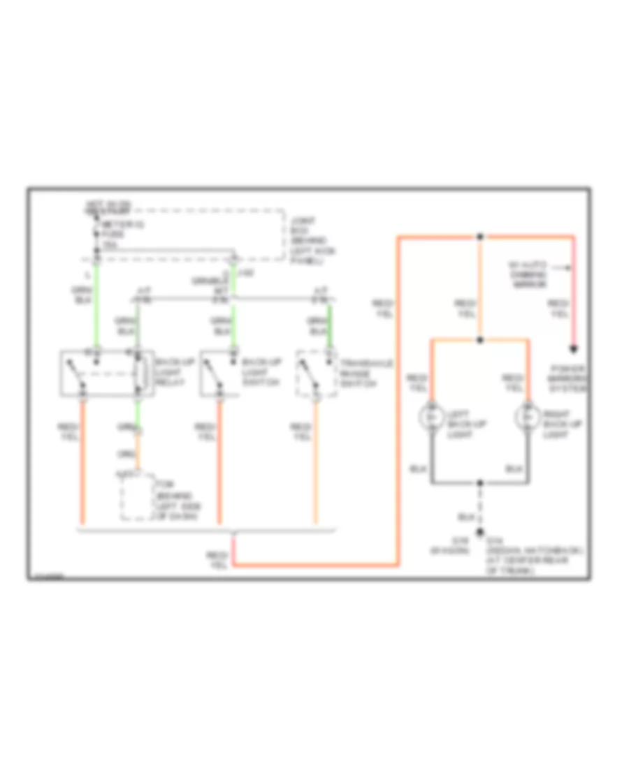
Backup Lamps Wiring Diagram for Mazda 6 i 2005
List of elements for Backup Lamps Wiring Diagram for Mazda 6 i 2005:
- (behind left side of dash)
- A/t 2.3l
- A/t 3.0l
- A13
- Back-up light relay
- Back-up light switch
- G14 (sedan, hatchback) (at center rear of trunk)
- G19 (wagon)
- Hot in on or start
- Joint box (behind left kick panel)
- Left back-up light
- Meter ig fuse 15a
- Power mirrors system
- Right back-up light
- Tcm
- Transaxle range switch
- W/ auto dimming mirror
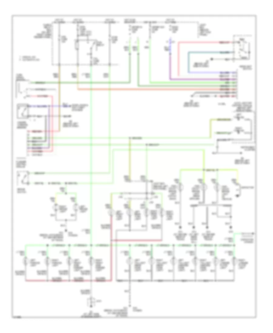
Exterior Lamps Wiring Diagram for Mazda 6 i 2005
List of elements for Exterior Lamps Wiring Diagram for Mazda 6 i 2005:
- (2.3l) (3.0l)
- Auto light-off control module (behind left side of dash)
- Automatic a/c
- Brake switch
- Capacitor
- Capacitor (wagon)
- Door locks & anti-theft systems
- Flasher control module
- Fuse & relay box (on left front inner fender panel)
- G1 (at left side of engine compt)
- G13 (at left rear door sill)
- G14 (at center rear of trunk)
- G14 (sedan, hatchback) (at center rear of trunk)
- G19
- G19 (wagon)
- G2 (behind left end of dash)
- G7 (behind left side of dash)
- G8 (behind left side of dash)
- Haz fuse 10a
- Hazard warning switch
- Head
- Headlight switch
- High mount brake light (hatch back)
- High mount brake light (in vehicle)
- High mount brake light (rear spoiler)
- Hot at all times
- Hot in acc
- Hot in on or start
- Instrument cluster
- J-01
- J-02
- J-05
- Jc-01
- Joint box (behind left kick panel)
- Left brake light
- Left front side marker light
- Left front turn light
- Left license plate light
- Left parking light
- Left rear turn light
- Left taillight (inboard comb light)
- Left taillight (rear comb light)
- Left turn ind
- Main fuse 100a 120a
- Manual a/c
- Meter acc fuse 5a
- Meter ig fuse 15a
- Off
- Right brake light
- Right front side marker light
- Right front turn light
- Right license plate light
- Right parking light
- Right rear turn light
- Right taillight (inboard comb light)
- Right taillight (rear comb light)
- Right turn ind
- Room fuse 15a
- Sedan
- Stop fuse 15a
- Tail fuse 10a
- Tns
- Tns relay
- Turn signal switch
- W/ drl
- Wagon
GROUND DISTRIBUTION
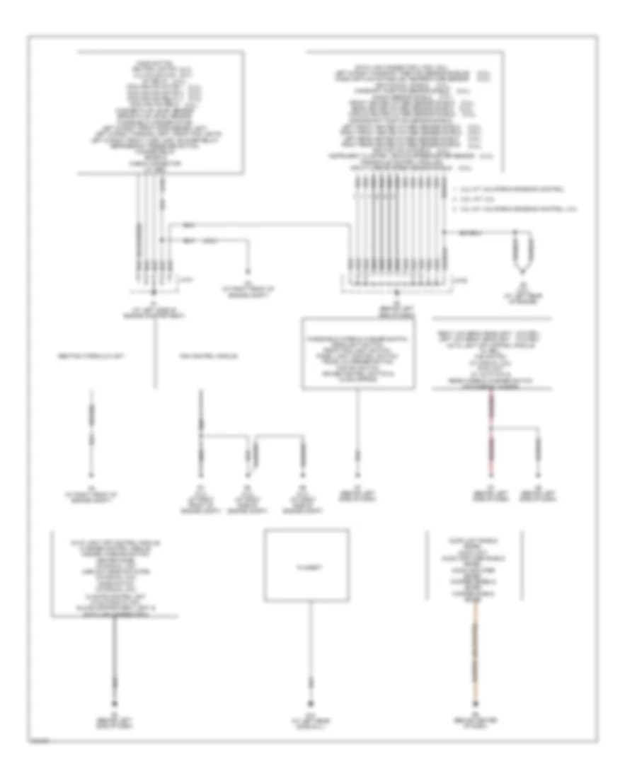
Ground Distribution Wiring Diagram (1 of 2) for Mazda 6 i 2005
List of elements for Ground Distribution Wiring Diagram (1 of 2) for Mazda 6 i 2005:
- (2.3l)
- (2.3l),
- (2.3l), (2.3l),
- (2.3l), (2.3l), (2.3l),
- (3.0l) (at right front of engine compt)
- (3.0l) (at right side of engine compt)
- (3.0l),
- (3.0l), (2.3l),
- (3.0l), (3.0l),
- (at left side of engine compartment)
- (at right front of engine compt)
- (m/t), (m/t),
- (w/abs)
- (w/o drl), (w/o drl)
- 2.3l a/t: california emission control
- 2.3l a/t: california emission control, 3.0l
- 2.3l: a/t, 3.0l
- Abs/tcs hydraulic unit
- Audio unit shield (bose), audio unit, audio amplifier shield (bose), audio amplifier (bose), woofer (bose) & (bose) woofer shield (bose)
- Auto light off control module (w/ drl), fan switch (w/ manual a/c), pwm unit (w/ auto a/c) & rear wiper & washer switch (hatchback, wagon)
- Auto light off control module, flasher control module, hazard warning switch, center panel (w/manual a/c), airflow mode actuator (w/manual a/c), mode switch (w/manual a/c),
- Climate control unit (w/automatic a/c), glove compartment light & data link connector 2
- Crankshaft position sensor shield, left front heated oxygen sensor shield right front heated oxygen sensor shield left rear heated oxygen sensor shield right rear heated oxygen sensor shield ignition coils shield instrument cluster, vehicle speedometer sensor transaxle control module & input/turbine speed sensor shield
- Data link connector 2, pcm, coil, left & right camshaft position sensor shields mass air flow/intake air temperature sensor ignition coil shield camshaft position sensor shield knock sensor shield front heated oxygen sensor shield rear heated oxygen sensor shield middle heated oxygen sensor shield
- Fan control module
- Filament
- G18 (at left rear door sill)
- G2 (behind left end of dash)
- G3 (3.0l) (at left rear of engine)
- G4 (at right front of engine compt)
- G7 (behind left side of dash)
- G8 (behind left side of dash)
- G9 (behind center of dash)
- Hood switch, neutral switch clutch switch ig1 relay cooling fan motor 1 cooling fan motor 2 cooling fan relay 4 cooling fan relay washer fluid level sensor, brake fluid level sensor, windshield washer motor, left & right front side marker light,
- Jc-01
- Jc-02
- Left & right front turn light, blower relay, refrigerant pressure switch, woofer relay (bose) & check connector (w/ abs)
- Left & right parking light, front fog lights,
- Right low beam headlight left low beam headlight
- Windshield wiper & washer switch, headlight switch, front fog light switch, panel light control switch, trunk lid opener switch, tcs off switch, cruise control switch & clock spring
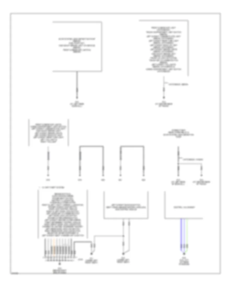
Ground Distribution Wiring Diagram (2 of 2) for Mazda 6 i 2005
List of elements for Ground Distribution Wiring Diagram (2 of 2) for Mazda 6 i 2005:
- (hatchback)
- (wagon)
- Brake switch 2, audio dimming mirror, power seat switch, ashtray illumination, windshield wiper motor, right & left vanity mirror illumination, power window main switch, door lock control module, right & left door lock switch, left door key cylinder switch/ left door lock-link switch, power outer mirror switch, left & right heated outer mirror, theft deterrent control module, right front door lock link switch, cigarette lighter, accessory socket, left rear door lock-link switch, right rear door lock-link switch, selector lever component & left & right seat warmer unit & switch
- Cargo compartment light switch (hatchback)
- Control valve body
- Evap system leak detection pump (sedan), fuel pump unit, high mount brake light (in-vehicle) (sedan), front & rear map lights & (sedan)
- Front & rear map light (hatchback), trunk compartment light switch (sedan), left & right license plate light (sedan, hatchback), left & right rear turn light (sedan, hatchback), left & right back up light (sedan, hatchback), left & right brake lights (sedan, hatchback), high mount brake light (sedan, hatchback), trunk lid lock actuator, trunk key cylinder switch (sedan), left & right taillights (sedan, hatchback) &
- Front & rear map lights, cargo compartment light switch, left & right license plate light, high mount brake light, left & right brake lights, left & right back-up light, left & right rear turn light, left taillight & right taillight
- G10 (behind right end of dash)
- G11 (under left front seat)
- G12 (under left front seat)
- G13 (at left rear door sill)
- G13 (at left rear of door sill)
- G14 (at center rear of trunk)
- G16 (2.3l: a/t) (at rear of engine)
- G19
- G20
- G21
- G22
- Hatchback, sedan
- Hatchback, wagon
- Intermittent rear wiper relay & evap system leak detection pump
- Jc-03
- Left & right buckle switch, seat weigh sensor control module & sas control module
- W/ anti-theft system
HEADLIGHTS
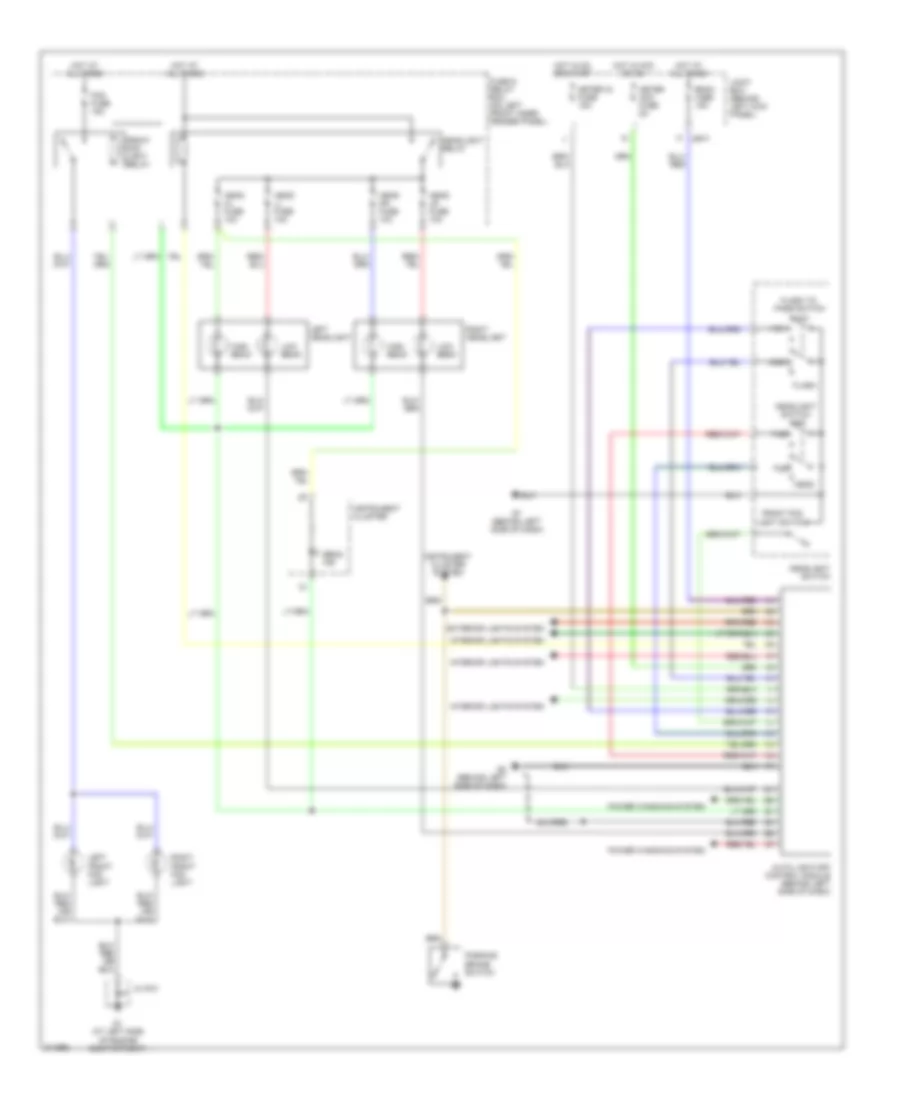
Headlights Wiring Diagram, with DRL for Mazda 6 i 2005
List of elements for Headlights Wiring Diagram, with DRL for Mazda 6 i 2005:
- Auto light-off control module (behind left side of dash)
- Beam ind
- Exterior lights system
- Flash
- Flash to pass switch
- Fog fuse 15a
- Front fog light relay
- Front fog light switch
- Fuse & relay box (on left front inner fender panel)
- G1 (at left side of engine compartment)
- G7 (behind left side of dash)
- G8 (behind left side of dash)
- Head
- Head hl fuse 10a
- Head hr fuse 10a
- Head ll fuse 10a
- Head lr fuse 10a
- Headlight relay
- Headlight switch
- High
- High beam
- Hot at all times
- Hot in acc or on
- Hot in on or start
- Instrument cluster
- Instrument cluster system
- Interior lights system
- Jb-01
- Jc g-01
- Joint box (behind left kick panel)
- Left front fog light
- Left headlight
- Low
- Low beam
- Meter acc fuse 5a
- Meter ig fuse 15a
- Off
- Parking brake switch
- Power windows system
- Right front fog light
- Right headlight
- Room fuse 15a
- Tns
Headlights Wiring Diagram, without DRL for Mazda 6 i 2005
List of elements for Headlights Wiring Diagram, without DRL for Mazda 6 i 2005:
- Auto light-off control module (behind left side of dash)
- Beam ind
- Exterior lights system
- Flash
- Flash to pass switch
- Fog fuse 15a
- Front fog light relay
- Front fog light switch
- Fuse & relay box (on left front inner fender panel)
- G1 (at left side of engine compartment)
- G7 (behind left side of dash)
- G8 (behind left side of dash)
- Head
- Head hl fuse 10a
- Head hr fuse 10a
- Head ll fuse 10a
- Head lr fuse 10a
- Headlight relay
- Headlight switch
- High
- High beam
- Hot at all times
- Hot in acc or on
- Hot in on or start
- Instrument cluster
- Interior lights system
- Jb-01
- Jc g-01
- Joint box (behind left kick panel)
- Left front fog light
- Left headlight
- Low
- Low beam
- Meter acc fuse 5a
- Meter ig fuse 15a
- Off
- Power windows system
- Right front fog light
- Right headlight
- Room fuse 15a
- Tns
HORN
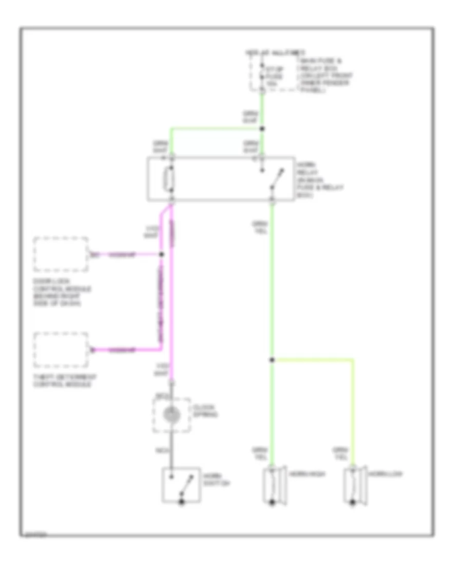
Horn Wiring Diagram for Mazda 6 i 2005
List of elements for Horn Wiring Diagram for Mazda 6 i 2005:
- (w/theft-deterrent)
- Clock spring
- Door lock control module (behind right side of dash)
- Horn switch
- Horn high
- Horn low
- Horn relay (in main fuse & relay box)
- Hot at all times
- Main fuse & relay box (on left front inner fender panel)
- Nca
- Stop fuse 15a
- Theft-deterrent control module
INSTRUMENT CLUSTER
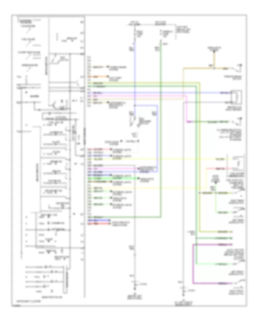
Instrument Cluster Wiring Diagram for Mazda 6 i 2005
List of elements for Instrument Cluster Wiring Diagram for Mazda 6 i 2005:
- (w/ black out meter)
- A/t ind
- Abs ind
- Air bag ind
- Anti-theft system
- Auto light-off control module (behind left side of dash)
- Beam ind
- Brake fluid level sensor
- Brake ind
- Buzzer
- Charge ind
- Computer data lines system
- Cruise main ind
- Cruise set ind
- Door ind
- Door locks system
- Drive circuit
- Exterior lights system
- Fuel gauge
- Fuel gauge sender unit
- Fuel low ind
- Fuel pump unit (under rear seat, on fuel tank)
- G1 (at left side of engine compt)
- G2 (behind left end of dash)
- Gear position ind
- Headlights system
- Hot at all times
- Hot in on or start
- Illum ind
- Instrument cluster
- Interior lights system
- Jb-01
- Jc g-01
- Jc g-02
- Joint box (behind left kick panel)
- Key reminder switch
- Left front door switch
- Left rear door switch
- Left turn ind
- Meter ig fuse 15a
- Microcomputer
- Mil ind
- Odometer/ tripmeter
- Oil ind
- Oil pressure switch (2.3l: at left rear of engine) (3.0l: at left front of engine)
- Parking brake switch
- Red
- Right front door switch
- Right rear door switch
- Right turn ind
- Room fuse 15a
- Seat belt ind
- Security ind
- Speedometer
- Tachometer
- Tcs off ind
- Tns ind
- Trip switch
- Washer ind
- Water temp gauge
- Wiper/washer system
INTERIOR LIGHTS
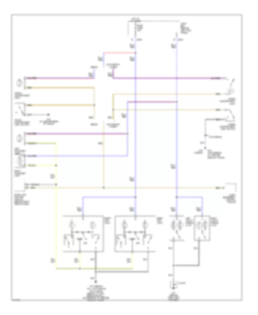
Courtesy Lamps Wiring Diagram for Mazda 6 i 2005
List of elements for Courtesy Lamps Wiring Diagram for Mazda 6 i 2005:
- (sedan) (hatchback)
- (sedan: at left rear door sill) (hatchback: at center rear of trunk)
- (wagon)
- Cargo compartment light
- Cargo compartment light switch
- Door
- Door lock control module (behind right side of dash)
- Front map light
- G10 (behind right end of dash)
- G13
- G14
- G14 (at center rear of trunk)
- G14 (hatchback) (at center rear of trunk)
- G19
- G19 (wagon)
- Hatchback
- Hatchback/ wagon
- Hot at all times
- Jb-03
- Jb-05
- Jc g-03
- Joint box (behind left kick panel)
- Left courtesy light
- Left vanity mirror illum
- Off
- Rear map light
- Right courtesy light
- Right vanity mirror illum
- Room fuse 15a
- Sedan
- Theft deterrent control module
- Trunk compartment light
- Trunk compartment light switch
Instrument Illumination Wiring Diagram for Mazda 6 i 2005
List of elements for Instrument Illumination Wiring Diagram for Mazda 6 i 2005:
- (2.3l) (3.0l)
- (behind left end of dash) g2
- (behind right end of dash)
- Anti-theft system
- Ashtray
- Audio control switch illum (w/ audio control switch)
- Audio unit
- Auto light-off control module (behind left side of dash)
- Climate control unit (w/ auto a/c)
- Clock spring
- Cruise control switch illum
- Fuse & relay box (on left front inner fender panel)
- G10
- G7 (behind left side of dash)
- G8 (behind left side of dash)
- Glove compartment light
- Head
- Headlight switch
- Hot at all times
- Hot in acc or run
- Hot in on or start
- Ignition key illum
- Illum
- Illum fuse 10a
- Illumination 2f
- Instrument cluster
- Instrument cluster & warning systems
- J/c g-02
- J/c g-03
- Jb-01
- Jb-02
- Joint box (behind left kick panel)
- Left front door switch
- Left rear door switch
- Left seat warmer switch (w/ seat warmer)
- Main fuse 100a 120a
- Meter acc fuse 5a
- Meter ig fuse 15a
- Microcomputer
- Nca
- Off
- Oscillator
- Panel light control switch
- Right front door switch
- Right rear door switch
- Right seat warmer switch (w/ seat warmer)
- Room fuse 15a
- Selector level component
- Sound systems
- Steering wheel
- Tcs off switch illumination (w/ abs)
- Tns
- Tns relay
POWER DISTRIBUTION
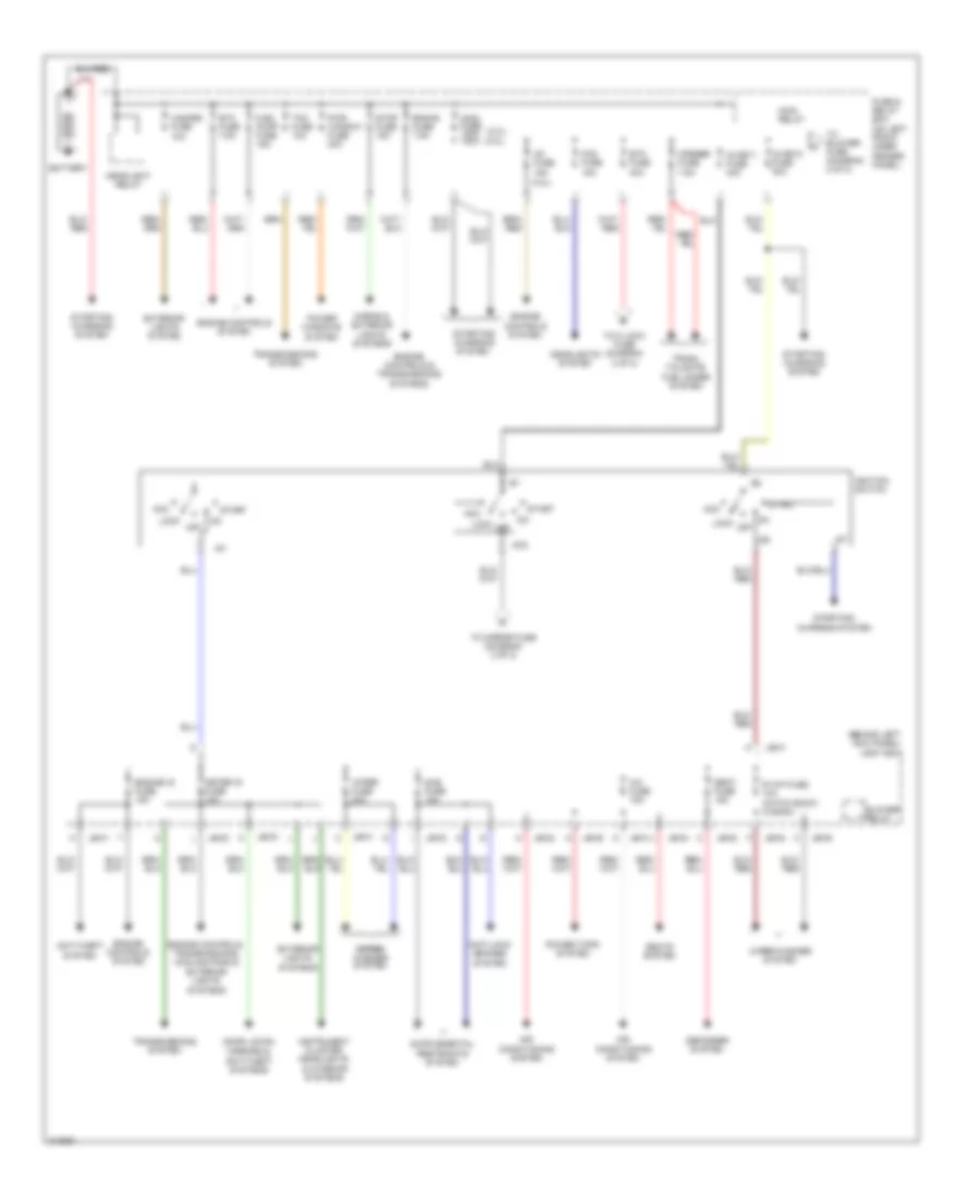
Power Distribution Wiring Diagram (1 of 2) for Mazda 6 i 2005
List of elements for Power Distribution Wiring Diagram (1 of 2) for Mazda 6 i 2005:
- (2.3l) (3.0l)
- (3.0l)
- (behind left kick panel) joint box
- A/c fuse 15a
- Acc
- Air conditioning system
- Anti-lock brakes system
- Anti-theft system
- Battery
- Blower relay
- Btn fuse 40a
- Defogger system
- Door locks, mirrors & anti-theft systems
- Eng+b fuse 7.5a
- Engine controls & transmissions systems
- Engine controls system
- Engine controls, transmissions, cooling fans & exterior lights systems
- Engine ig fuse 15a
- Etc fuse 7.5a
- Exterior lights system
- Exterior lights systems
- Fog fuse 15a
- Fuel pump fuse 15a
- Fuse & relay box (on left front inner fender panel)
- Hazard fuse 10a
- Headlight relay
- Headlights system
- Horns & exterior lights systems
- Ig key1 fuse 40a
- Ig key2 fuse 30a
- Ig1
- Ig1 fuse 15a
- Ig2
- Ignition switch
- Instrument cluster headlights & interior systems
- Jb-01
- Jb-01 j
- Jb-02
- Jb-03
- Jb-05
- Lock
- Main fuse 100a 120a
- Main relay
- Meter ig fuse 15a
- Off
- Opener fuse 7.5a
- Power tops system
- Power windows system
- Pwr window fuse 30a
- R wip fuse 10a (hatch back/ wagon)
- Sas fuse 15a
- Seat fuse 15a
- Seats system
- Start
- Starting/ charging system
- Stop fuse 15a
- Tcm fuse 10a
- To blower fuse (diagram 2 of 2)
- To d lock fuse (diagram 2 of 2)
- To mirror fuse (diagram 2 of 2)
- Transmissions system
- Trunk, tailgate, fuel doors system
- Wiper fuse 20a
- Wiper/ wiper/ washer system
- Wiper/washer system
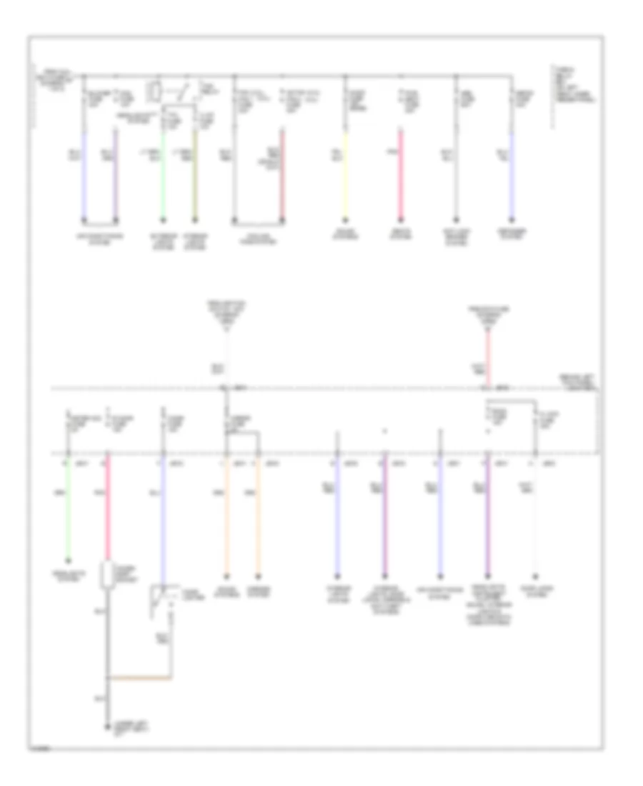
Power Distribution Wiring Diagram (2 of 2) for Mazda 6 i 2005
List of elements for Power Distribution Wiring Diagram (2 of 2) for Mazda 6 i 2005:
- (2.3l)
- (3.0l)
- (behind left kick panel) joint box
- (under left front seat) g11
- Abs fuse 60a
- Acces- sory socket
- Ad fan
- Air conditioning
- Anti-lock brakes system
- Audio fuse 15a (bose)
- Blower fuse 40a
- Cigar fuse 15a
- Cigar lighter
- Cooling fans system
- D lock fuse 30a
- Defog fuse 40a
- Defogger system
- Door locks system
- Exterior lights system
- Fan
- Fan 1 fuse 30a
- Fan 2 fuse 30a
- From btn fuse (diagram 1 of 2)
- From ig key2 fuse a (diagram 1 of 2)
- From ignition switch acc (diagram 1 of 2)
- Fuse & relay box (on left front inner fender panel)
- Headlights system
- Headlights, instrument cluster, sound, interior lights & computer data lines systems
- Illum fuse 10a
- Interior lights system
- Interior lights, door locks, mirrors & anti-theft systems
- Jb-01
- Jb-02
- Jb-03
- Jb-05
- Mag fuse 10a
- Meter acc fuse 5a
- Mirror fuse 5a
- Mirrors system
- Pnk
- Pwr seat fuse 30a
- R cigar fuse 15a
- Room fuse 15a
- Seats system
- Sound systems
- System
- Tail fuse 10a
- Tns relay
POWER DOOR LOCKS
Power Door Locks Wiring Diagram for Mazda 6 i 2005
List of elements for Power Door Locks Wiring Diagram for Mazda 6 i 2005:
- (at rear of left rear door)
- (at rear of right front door)
- (at rear of right rear door)
- Anti-theft system
- Auto light-off control module (behind left side of dash)
- D lock fuse 30a
- Door ind
- Door lock control module (behind right side of dash)
- Exterior lights system
- Fuse & relay box (on left front inner fender panel)
- G10 (behind right end of dash)
- G14 (at center rear of trunk)
- G7 (behind left side of dash)
- Hot at all times
- Hot in on or start
- Instrument cluster
- Interior lights system
- Jb-01
- Jb-03
- Jc g-03
- Joint box (behind left kick panel)
- Left door lock switch
- Left front door lock actuator (at rear of left front door)
- Left front door lock link switch/ left door key cylinder switch
- Left rear door lock actuator
- Left rear door switch
- Liftgate lock actuator (5hb/wagon)
- Meter ig fuse 15a
- Opener fuse 7.5a
- Right door lock switch
- Right front door lock actuator
- Right rear door lock actuator
- Right rear door switch
- Room fuse 15a
- Theft deterrent control module
- Trunk lid cancel switch
- Trunk lid lock actuator
- Trunk lid opener relay
- Trunk lid opener switch
- Unlk
- Warning & anti-theft systems
POWER MIRRORS
Power Mirrors Wiring Diagram for Mazda 6 i 2005
List of elements for Power Mirrors Wiring Diagram for Mazda 6 i 2005:
- Auto dimming mirror
- Defogger system
- Down
- G10 (behind right end of dash)
- Heated outside mirror
- Hot at all times
- Hot in acc or run
- Hot in run or start
- Jb-03
- Jc g-03
- Joint box (behind left kick panel)
- Left
- Left power outside mirror (at mirror)
- Left/ up
- Left/right
- Meter ig fuse 15a
- Mirror fuse 5a
- Operation switch
- Power outside mirror switch
- Right
- Right power outside mirror (at mirror)
- Right/ down
- Room fuse 15a
- Select switch
- Transmissions & exterior lights system
- Up/down
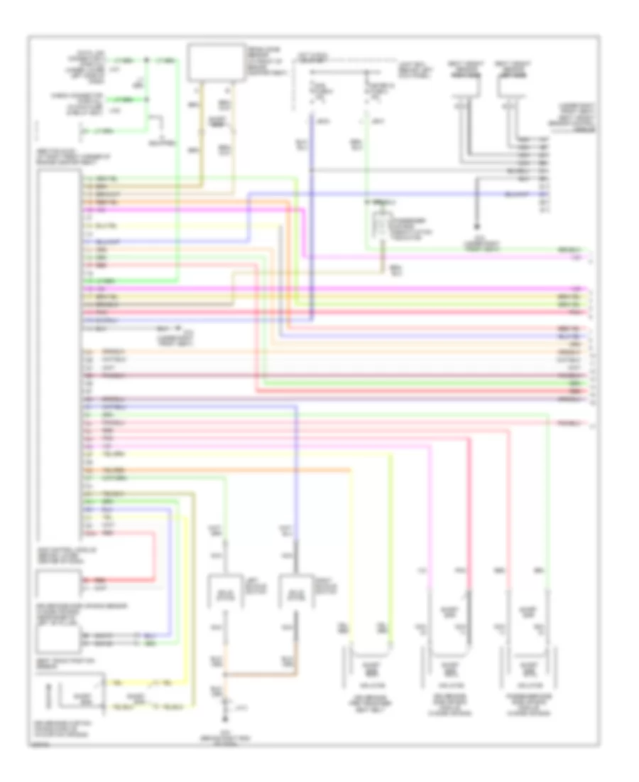
POWER SEATS
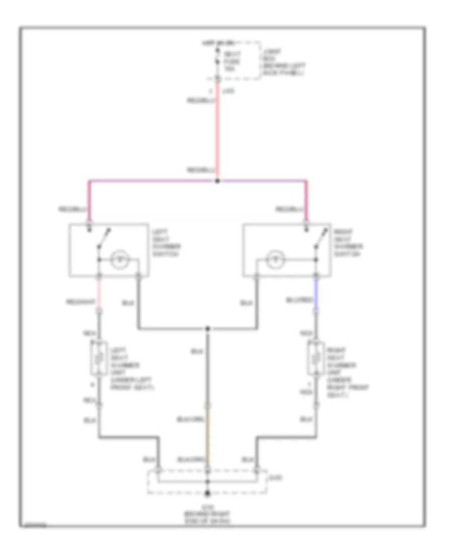
Heated Seats Wiring Diagram for Mazda 6 i 2005
List of elements for Heated Seats Wiring Diagram for Mazda 6 i 2005:
- G-03
- G10 (behind right end of dash)
- Hot in on
- J-03
- Joint box (behind left kick panel)
- Left seat warmer switch
- Left seat warmer unit (under left front seat)
- Nca
- Right seat warmer switch
- Right seat warmer unit (under right front seat)
- Seat fuse 15a
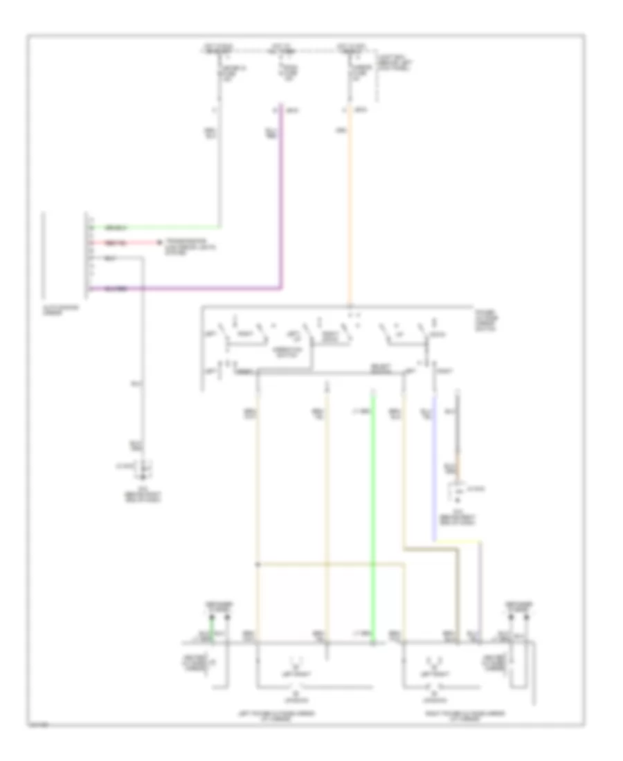
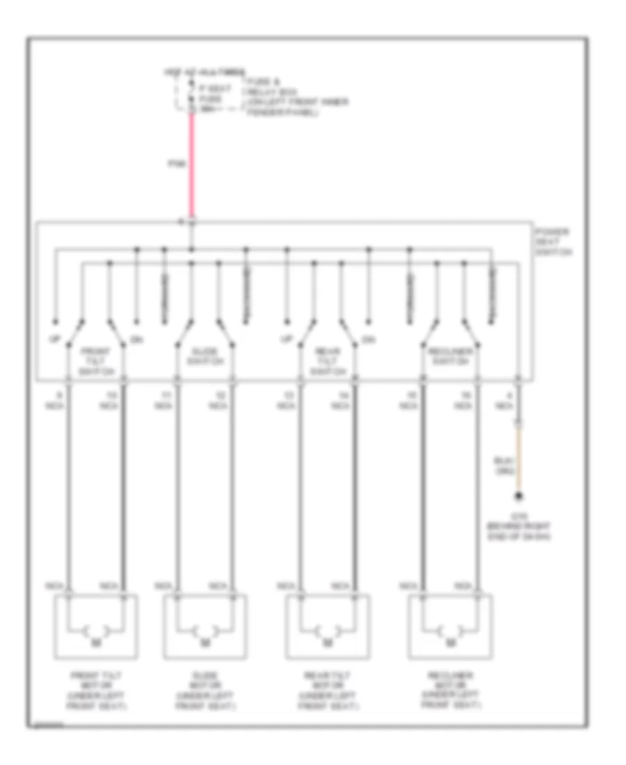
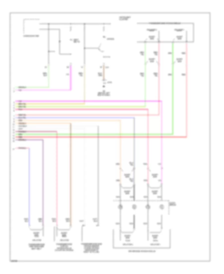
Power Seat Wiring Diagram for Mazda 6 i 2005
List of elements for Power Seat Wiring Diagram for Mazda 6 i 2005:
- Backward
- Forward
- Front tilt motor (under left front seat)
- Front tilt switch
- Fuse & relay box (on left front inner fender panel)
- G10 (behind right end of dash)
- Hot at all times
- Nca
- P seat fuse 30a
- Pnk
- Power seat switch
- Rear tilt motor (under left front seat)
- Rear tilt switch
- Recliner motor (under left front seat)
- Recliner switch
- Slide motor (under left front seat)
- Slide switch
POWER TOP/SUNROOF
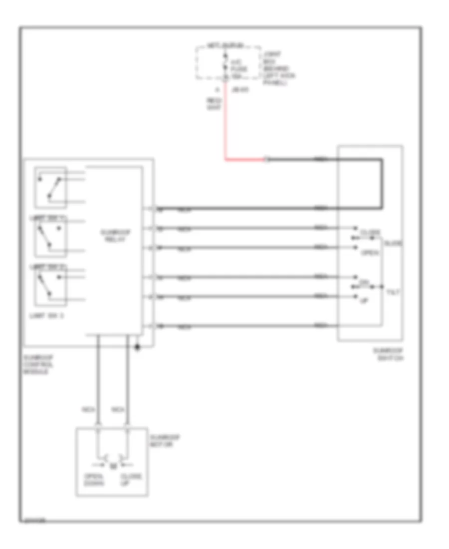
Power Top/Sunroof Wiring Diagram for Mazda 6 i 2005
List of elements for Power Top/Sunroof Wiring Diagram for Mazda 6 i 2005:
- A/c fuse 15a
- Close
- Close, up
- Hot in run
- Jb-05
- Joint box (behind left kick panel)
- Limit sw 1
- Limit sw 2
- Limit sw 3
- Nca
- Open
- Open, down
- Slide
- Sunroof control module
- Sunroof motor
- Sunroof relay
- Sunroof switch
- Tilt
POWER WINDOWS
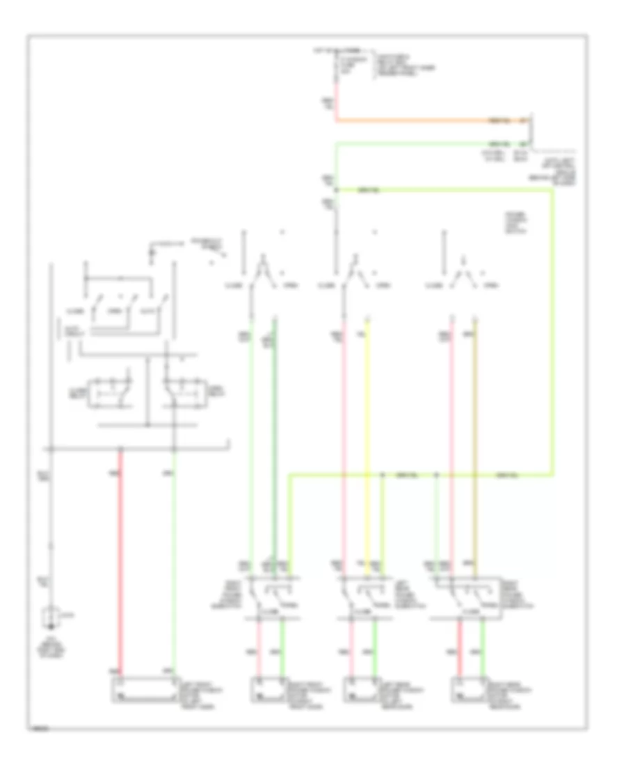
Power Windows Wiring Diagram for Mazda 6 i 2005
List of elements for Power Windows Wiring Diagram for Mazda 6 i 2005:
- (w/ drl)
- (w/o drl)
- Auto
- Auto circuit
- Auto light- off control module (behind left side of dash)
- Close
- Close relay
- E1-04
- E2-04
- G10 (behind right end of dash)
- Hot at all times
- Jc-03
- Left front power window motor (in left front door)
- Left rear power window motor (in left rear door)
- Left rear power window subswitch
- Main fuse & relay box (on left front inner fender panel)
- Open
- Open relay
- P window fuse 30a
- Power window main switch
- Power-cut switch
- Red
- Right front power window motor (in right front door)
- Right front power window subswitch
- Right rear power window motor (in right rear door)
- Right rear power window subswitch
RADIO
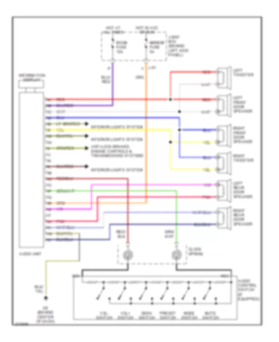
Radio Wiring Diagram, Base for Mazda 6 i 2005
List of elements for Radio Wiring Diagram, Base for Mazda 6 i 2005:
- (if equipped)
- Anti-lock brakes, engine controls & transmissions systems
- Audio control switch
- Audio unit
- Clock spring
- G9 (behind center of dash)
- Hot at all times
- Hot in acc or run
- Information display
- Interior lights system
- J-01 v
- Joint box (behind left kick panel)
- Left front door speaker
- Left rear door speaker
- Left tweeter
- Mirror fuse 5a
- Mode switch
- Mute switch
- Nca
- Pnk
- Preset switch
- Red
- Right front door speaker
- Right rear door speaker
- Right tweeter
- Room fuse 15a
- Seek switch
- Vol+ switch
- Vol- switch
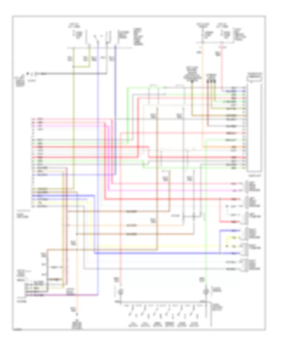
Radio Wiring Diagram, Bose for Mazda 6 i 2005
List of elements for Radio Wiring Diagram, Bose for Mazda 6 i 2005:
- Anti-lock brakes, engine controls & transmissions systems
- Audio amplifier
- Audio control switch
- Audio fuse 15a
- Audio unit
- Clock spring
- Fuse & relay box (on left front inner fender)
- G1 (at left side of engine compt)
- G9 (behind center of dash)
- Hatch back/ wagon
- Hot at all times
- Hot in acc or run
- Information display
- Interior lights system
- Jc c-28
- Jc g-01
- Joint box (behind left kick panel)
- Left front door speaker
- Left rear door speaker
- Left tweeter
- Mirror fuse 5a
- Mode switch
- Mute switch
- Nca
- P j-01
- Pnk
- Preset switch
- Red
- Right front door speaker
- Right rear door speaker
- Right tweeter
- Room fuse 15a
- Sedan
- Seek switch
- Vol+ switch
- Vol- switch
- Woofer
- Woofer relay (bose)
STARTING/CHARGING
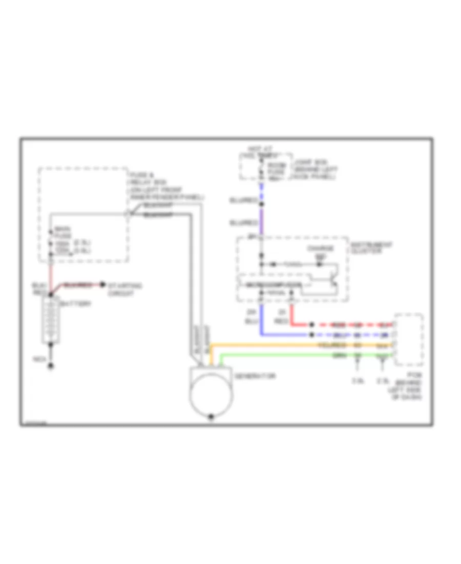
Charging Wiring Diagram for Mazda 6 i 2005
List of elements for Charging Wiring Diagram for Mazda 6 i 2005:
- (2.3l)
- (3.0l)
- 1aa
- 1ad
- 2.3l
- 3.0l
- Battery
- Charge ind
- Fuse & relay box (on left front inner fender panel)
- Generator
- Hot at all times
- Instrument cluster
- Joint box (behind left kick panel)
- Main fuse 100a 120a
- Microcomputer
- Nca
- Pcm (behind left side of dash)
- Red
- Room fuse 15a
- Starting circuit
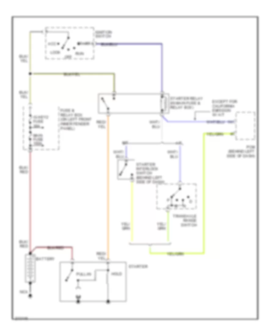
2.3L
2.3L, Starting Wiring Diagram for Mazda 6 i 2005
List of elements for 2.3L, Starting Wiring Diagram for Mazda 6 i 2005:
- A/t
- Acc
- Battery
- Except for california emission w/ a/t
- Fuse & relay box (on left front inner fender panel)
- Hold
- Ig key2 fuse 30a
- Ignition switch
- Lock
- M/t
- Main fuse 100a
- Nca
- Off
- Pcm (behind left side of dash)
- Pull-in
- Run
- Start
- Starter
- Starter interlock switch (behind left side of dash)
- Starter relay (in main fuse & relay box)
- Transaxle range switch
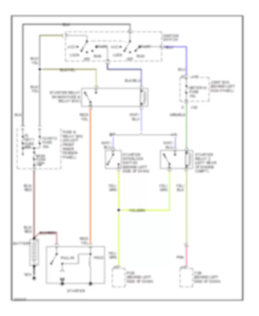
3.0L
3.0L, Starting Wiring Diagram for Mazda 6 i 2005
List of elements for 3.0L, Starting Wiring Diagram for Mazda 6 i 2005:
- A/t
- Acc
- Battery
- Fuse & relay box (on left front inner fender panel)
- Hold
- Ig key1 fuse 40a
- Ig key2 fuse 30a
- Ignition switch
- J-01
- J-02
- Joint box (behind left kick panel)
- Lock
- M/t
- Main fuse 120a
- Meter ig fuse 15a
- Nca
- Off
- Pcm (behind left side of dash)
- Pnk
- Pull-in
- Run
- Start
- Starter
- Starter interlock switch (behind left side of dash)
- Starter relay (in main fuse & relay box)
- Starter relay 2 (left rear of engine compt)
- Tcm (behind left side of dash)
SUPPLEMENTAL RESTRAINTS
Supplemental Restraints Wiring Diagram (1 of 2) for Mazda 6 i 2005
List of elements for Supplemental Restraints Wiring Diagram (1 of 2) for Mazda 6 i 2005:
- (under right front seat)
- (under right front seat) seat weight sensor control module
- 2aa
- Abs/tcs hu/cm (at right front corner of engine compartment)
- Check connector (partial) (in main fuse & relay box)
- Crash zone sensor (at front of engine compartment)
- Data link connector 2 (partial) (under lower left side of dash)
- Driver-side curtain air bag module (w/curtain air bag)
- Driver-side pre-tensioner seat belt
- Driver-side side air bag module (w/side air bag)
- Driver-side side air bag sensor (w/side air bag) (near base of left "b" pillar)
- G10 (behind right end of dash)
- G12
- G12 (under right front seat)
- Hot in run or start
- If equipped
- Inflator
- J/c 3
- Jb-01
- Jb-03
- Joint box (behind left kick panel)
- Left buckle switch
- Meter ig fuse 2 15a
- Nca
- Nca (1)
- Nca (2)
- Nca (7)
- Nca (8)
- Passenger air bag deactivation indicator
- Passenger-side side air bag module (w/side air bag)
- Pnk
- Red
- Right buckle switch
- Sas control module (behind lower center of dash)
- Sas fuse 6 15a
- Seat track position sensor
- Seat weight sensor left side
- Seat weight sensor right side
- Short bar
- Solid state
- U-01
- U-02
Supplemental Restraints Wiring Diagram (2 of 2) for Mazda 6 i 2005
List of elements for Supplemental Restraints Wiring Diagram (2 of 2) for Mazda 6 i 2005:
- Air bag
- C-01
- Clock spring
- Driver-side air bag module
- G2 (behind left end of dash)
- Inflator
- Inflator 1
- Inflator 2
- Instrument cluster
- Jc-02
- Microcomputer
- Nca
- Passenger-side air bag module
- Passenger-side curtain air bag module (w/curtain air bag)
- Passenger-side pre-tensioner seat belt
- Passenger-side side air bag sensor (w/side air bag) (near base of right "b" pillar)
- Pnk
- Red
- Seat belts
- Short bar
TRANSMISSION
2.3L
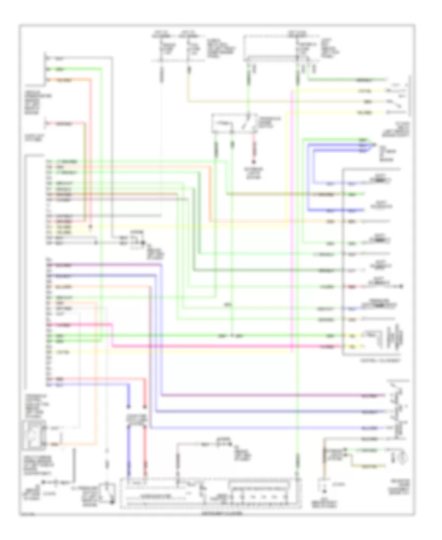
2.3L, A/T Wiring Diagram for Mazda 6 i 2005
List of elements for 2.3L, A/T Wiring Diagram for Mazda 6 i 2005:
- A/t ind
- At main relay (left rear of engine compt)
- Audio unit (w/o abs)
- Computer data lines system
- Control valve body
- Eng+b fuse 7.5a
- Exterior lights system
- Fuse & relay box (on left front inner fender panel)
- G10 (behind right end of dash)
- G16 (at rear of engine)
- G2 (behind left end of dash)
- G2 (behind left side of dash)
- Gear position ind
- Hot at all times
- Hot in on or start
- Illum
- Input/turbine speed sensor (at left side of engine compartment)
- Instrument cluster
- Interior lights system
- Jb-01
- Jb-02
- Jc g-02
- Jc g-03
- Joint box (behind left kick panel)
- Meter ig fuse 15a
- Microcomputer
- Oil pressure switch (at left rear of engine)
- Pressure control solenoid
- Range m
- Red
- Selector indicator circuit
- Selector lever component (sport a/t)
- Sensor temperature fluid transaxle
- Shift solenoid a
- Shift solenoid b
- Shift solenoid c
- Shift solenoid d
- Shift solenoid e
- Switch down
- Switch up
- Tcm fuse 10a
- Transaxle control module (tcm) (behind left side of dash)
- Transaxle range switch
- Vehicle speedometer sensor (at left rear of engine)
3.0L
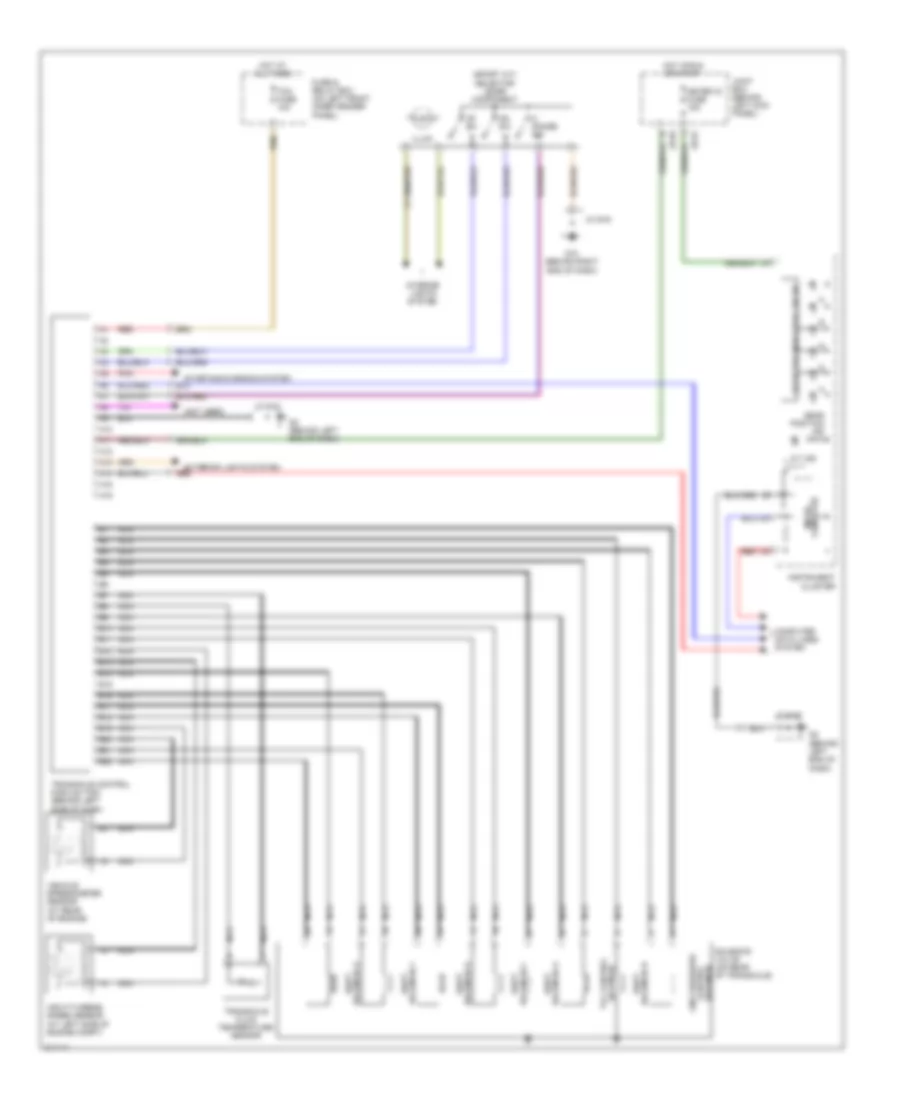
3.0L, A/T Wiring Diagram for Mazda 6 i 2005
List of elements for 3.0L, A/T Wiring Diagram for Mazda 6 i 2005:
- (behind left end of dash)
- (not used)
- (sport a/t) selector lever component
- A/t ind
- A10
- A11
- A12
- A13
- A14
- A15
- A16
- B10
- B11
- B12
- B13
- B14
- B15
- B16
- B17
- B18
- B19
- B20
- B21
- B22
- Computer data lines system
- Dn sw
- Exterior lights system
- Fuse & relay box (on left front inner fender panel)
- G10 (behind right end of dash)
- G2 (behind left end of dash)
- Gear position ind
- Hot at all times
- Hot in run or start
- Illum
- Input/turbine speed sensor (at left side of engine compt)
- Instrument cluster
- Interior lights system
- Jb-01
- Jb-02
- Jc g-02
- Jc g-03
- Joint box (behind left kick panel)
- Line pressure control solenoid
- M range sw
- Meter ig fuse 15a
- Micro- computer
- Nca
- Pnk
- Red
- Selector indicator circuit
- Shift solenoid a
- Shift solenoid d
- Shift solenoid e
- Solenoid b shift
- Solenoid c shift
- Solenoid f shift
- Solenoid tcc control
- Solenoid valve (on rear of transaxle)
- Starting/charging system
- Tcm fuse 10a
- Transaxle control module (tcm) (behind left side of dash)
- Transaxle fluid temperature sensor
- Up sw
- Vehicle speedometer sensor (at rear of engine)
TRUNK, TAILGATE, FUEL DOOR
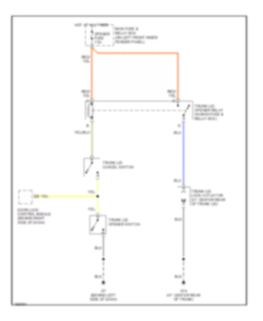
Trunk Release Wiring Diagram for Mazda 6 i 2005
List of elements for Trunk Release Wiring Diagram for Mazda 6 i 2005:
- Door lock control module (behind right side of dash)
- G14 (at center rear of trunk)
- G7 (behind left side of dash)
- Hot at all times
- Main fuse & relay box (on left front inner fender panel)
- Opener fuse 7.5a
- Trunk lid cancel switch
- Trunk lid lock actuator (at center rear of trunk lid)
- Trunk lid opener relay (in main fuse & relay box)
- Trunk lid opener switch
WARNING SYSTEMS
Warning Systems Wiring Diagram for Mazda 6 i 2005
List of elements for Warning Systems Wiring Diagram for Mazda 6 i 2005:
- Anti-theft system
- Auto light-off control module (behind left side of dash)
- Brake ind
- Buzzer
- Door ind
- G11 (under left front seat)
- Hall
- Headlights system
- Hot at all times
- Hot in run or start
- Instrument cluster
- Interior lights system
- Joint box (behind left kick panel)
- Key reminder switch
- Left buckle switch
- Left front door switch
- Left rear door switch
- Lights on/ illum input
- Meter ig fuse 15a
- Micro computer
- Nca
- P jb-01
- Parking brake switch
- Right buckle switch
- Right front door switch
- Right rear door switch
- Room fuse 15a
- Sas control module
- Seat belts ind
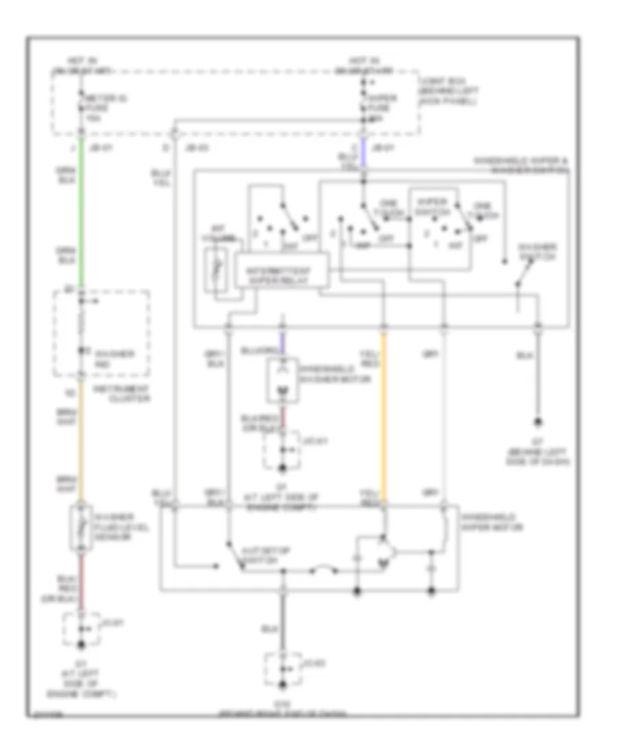
WIPER/WASHER
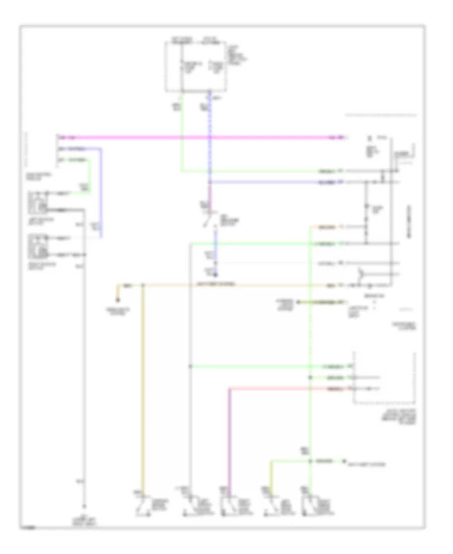
Front Wiper/Washer Wiring Diagram for Mazda 6 i 2005
List of elements for Front Wiper/Washer Wiring Diagram for Mazda 6 i 2005:
- Autostop switch
- G1 (at left side of engine compt)
- G10 (behind right end of dash)
- G7 (behind left side of dash)
- Hot in on or start
- Instrument cluster
- Int
- Int volume
- Intermittent wiper relay
- J/c-01
- Jb-01
- Jb-03
- Jc-01
- Jc-03
- Joint box (behind left kick panel)
- Meter ig fuse 15a
- Off
- Off int
- One touch
- Washer fluid level sensor
- Washer ind
- Washer switch
- Windshield washer motor
- Windshield wiper & washer switch
- Windshield wiper motor
- Wiper fuse 20a
- Wiper switch
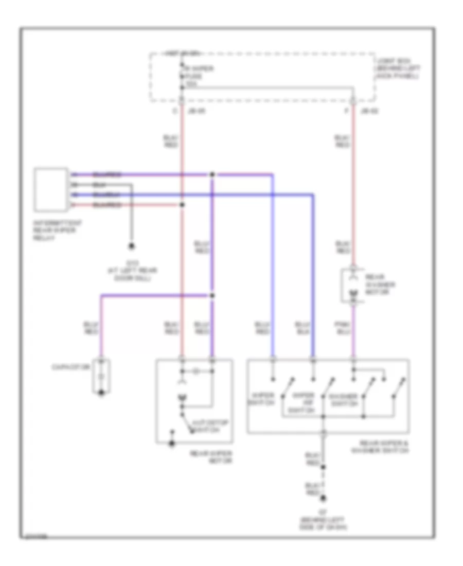
Rear Wiper/Washer Wiring Diagram for Mazda 6 i 2005
List of elements for Rear Wiper/Washer Wiring Diagram for Mazda 6 i 2005:
- Autostop switch
- Capacitor
- G13 (at left rear door sill)
- G7 (behind left side of dash)
- Hot in on
- Intermittent rear wiper relay
- Jb-02
- Jb-05
- Joint box (behind left kick panel)
- R wiper fuse 10a
- Rear washer motor
- Rear wiper & washer switch
- Rear wiper motor
- Washer switch
- Wiper int switch
- Wiper switch

 Čeština
 Dansk
Dansk Deutsch
 Ελληνικά
 English
 English
 Español
 Suomi
Suomi Français
 Français
 עברית
עברית Hrvatski
 Magyar
 日本語
日本語 한국어
한국어 Nederlands
 Polski
 Português
 Português
 Română
 Русский
 Slovenčina
 Slovenščina
 Svenska
 Türkçe
 中文 (中国)